

Oval EL4401, EL4211 Instructions Manual

Ins. No.
E-887-3N-E
BLEND OIL TEMPERATURE COMPENSATED
FLOW COMPUTER
Model : EL4401
This manual has been prepared to provide you with the information pertinent to the Blend Oil
Temperature Compensated FLOW COMPUTER.
With the proper application of the information and knowledge contained in this manual, you can expect
the best possible results over a long service life of this instrument. Keep this manual for ready reference.
It is suggested that the instruction manuals for the companion pulse generator (flowmeter) and receiving
instrument be referred to at the same time.
1

E-887-3N-E
TABLE OF CONTENTS
1. BEFORE YOU BEGIN ........................................................................................................................... 4
1.1 Confirming the Nameplate .............................................................................................................. 4
1.2 Transportation Precautions ............................................................................................................. 4
1.3 Storage Precautions ........................................................................................................................ 4
2. GENERAL ........................................................................................................................................... 5
2.1 Features ........................................................................................................................................ 5
2.2 Part Names ................................................................................................................................... 5
3. INSTALLATION ................................................................................................................................... 6
3.1 Outline Dimensions ....................................................................................................................... 6
3.2 Installation ..................................................................................................................................... 6
3.2.1 Installation Location ................................................................................................................ 6
3.2.2 Panel ....................................................................................................................................... 6
3.2.3 Installation ............................................................................................................................... 6
4. WIRING ................................................................................................................................................ 7
4.1 Field Wiring Cables ....................................................................................................................... 7
4.2 Wiring Connections ....................................................................................................................... 7
4.3 Description of Terminal Blocks for External Connections .............................................................. 7
5. GENERAL SPECIFICATIONS ............................................................................................................... 9
6. INTERNAL COMPONENTS AND FUNCTIONS ................................................................................ 10
6.1 Front Panel .................................................................................................................................. 10
6.1.1 Display .................................................................................................................................. 10
6.1.2 On-Screen Menu Items ......................................................................................................... 10
6.1.3 Error Messages ...................................................................................................................... 11
6.1.4 Front Panel Keypad .................................................................................................................11
7. CALCULATION FORMULAS ............................................................................................................... 12
7.1 Implementation of Meter Error Correction(Uncorrected total flow) ............................................ 12
7.2 Implementation of Temperature Correction on Petroleums (Corrected total flow) ........................ 13
7.3 Instant Flowrate (Corrected) ......................................................................................................... 13
8. PREPARATIONAL CHECKS AND OPERATION ................................................................................. 14
8.1 Preparation Before Operation ....................................................................................................... 14
8.2 Preparational Checks .................................................................................................................... 14
8.3 Operation ...................................................................................................................................... 14
9. TROUBLESHOOTING ........................................................................................................................ 15
10. ERROR MESSAGES .......................................................................................................................... 16
11. BEHAVIOR IN ERRATIC CONDITIONS .............................................................................................. 16
12. OVERALL BLOCK DIAGRAM ............................................................................................................. 17
13. PRODUCT CODE EXPLANATION ..................................................................................................... 18
CONVENTIONS
Shown in this manual are the signal words NOTE, CAUTION and WARNING, as described
in the examples below:
2
NOTE: Notes are separated from the general text to bring the user's attention to
important information.
CAUTION: Caution statements signal the user about hazards or unsafe practices
which could result in minor personal injury or product or property
damage.
WARNING: Warning statements signal the user about hazards or unsafe practices
which could result in severe personal injury or death.

E-887-3N-E
COMPANION VOLUME
KEY OPERATION MANUAL Ins. No. E-880TM-E
CONTENTS
1. KEY ARRANGEMENT ........................................................................................................... 10
2. DISPLAY SCREEN ................................................................................................................ 11
3. INITIAL CHECK ..................................................................................................................... 14
4. MODE SELECTION .............................................................................................................. 18
5. RUN MODE SCREEN ...........................................................................................................23
6. SET MODE ............................................................................................................................ 36
7. SYS MODE .........................................................................................................................142
8. EL4401 ................................................................................................................................ 170
9. EL4501 ................................................................................................................................ 175
10. DIP SWITCH CONFIGURATION ........................................................................................182
(※: Model with communication capabilities)
COMMUNICATION MANUAL (※) Ins. No. E-880CM-E
CONTENTS
1. COMMUNICATION CAPABILITY OVERVIEW ........................................................................5
2. NETWORK CONFIGURATION ............................................................................................... 5
3. MODE SELECTION ................................................................................................................ 6
4. LOCAL / REMOTE SELECTION .............................................................................................8
5. SETUP ITEMS FOR COMMUNICATION .............................................................................. 10
6. COMMUNICATION PROCEDURE........................................................................................ 11
7. COMMUNICATION FORMAT ................................................................................................12
8. BCC / SUM CHECK .............................................................................................................. 45
9. CR / LF .................................................................................................................................. 46
10. CODES ASSIGNED TO UNITS ............................................................................................. 48
11. ASCII CODE .......................................................................................................................... 49
3
E-887-3N-E
1. BEFORE YOU BEGIN
Every OVAL product is thoroughly tested and inspected before shipment from our factory.
When received, its appearance should be inspected for possible damage by rough handling during
transit. First of all, thoroughly read the handling precautions described in this section. For topics other
than those covered in this section, refer to the respective sections of this manual.
If at any time in the future you seek our assistance, contact the nearest sales office in your area.
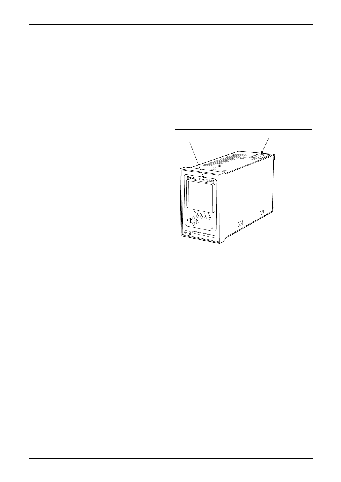
1.1 Confirming the Nameplate
The instrument is adjusted to individual specifications before shipment from our factory. Model
number appears on the nameplate attached to the
top of the housing.
Make sure to see that the instrument you received
conforms to the General Specifications and the
Product Code Explanation.
◆ When you inquire, supply complete informa-
tion as to the product name, model number,
product number, ratings, and other pertinent
information.
1.2 Transportation Precautions
※
Nameplate
(model number)
※ EL4001 is the
generic designation of the
EL4001 series
computers.
Fig. 1.1 Nameplate Location
(1) In order to safeguard against damage during transit, transport your instrument to the installation
location in the original package used for shipment from the factory if possible.
(2) Use care to avoid impact shocks to the instrument during transit.
1.3 Storage Precautions
If the instrument upon receipt is to be stored for extended periods of time before installation, unexpected
problems could arise. If such is the case, the following considerations should be taken:
(1) The instrument can best be stored in the original package used for transit from the factory.
(2) The place of storage should meet the following requirements:
☆ Free from rain and water
☆ Free from vibration and impact shocks
☆ With minimal temperature and humidity variation (around 25°C and 65% R.H.)
4
E-887-3N-E
MODEL
EL4001
TB
1
TB
3
PLS OUT3 TEMP IN TEMP IN FLOW IN
0V
+−
B bA
+−
+−+− +−
+−
SIG SUP
SUP
ANA OUTGND POWER
N
(
−
)
H
(
+
)
PRESS INPLS OUT1
PLS OUT2
1/1
OUT
TB
1
TB
2
TB
1
TB2TB
2
2. GENERAL
Using the most advanced electronic tehcnologies, this digital instrument has been developed specifically
for crude oil and heavy oil blend ratio measurement applications where accuracy is the prime
requirement.
In response to the flowrate, temperature, and blend ratio information arriving from the OVAL flowmeter, it
converts the flowrate to the equivalent volume flowrate under standard conitions and totalizes the flow.
An analog output and instant flowrate (corrected for meter error and temperature) output are additional
provisions.
2.1 Features
(1) Changing the meter factor, ranges of temperature and blend proportions, liquid kind, density, or other
parameters, of the companion flowmeter is simple by keystrokes on the front-panel keypad.
(2) Built around a microprocessor, the instrument carries out calculations entirely in digital signal
processing circuits to achieve a high degree of accuracy and reliability.
(3) Variables, such as temperature and pressure, can be reviewed on command with the front panel
keypad, whether or not calculation is in progress.
(4) A nonvolatile memory (E2PROM) retains all parameters and variables. Variables are resettable
following a power cycle or reset if so configured.
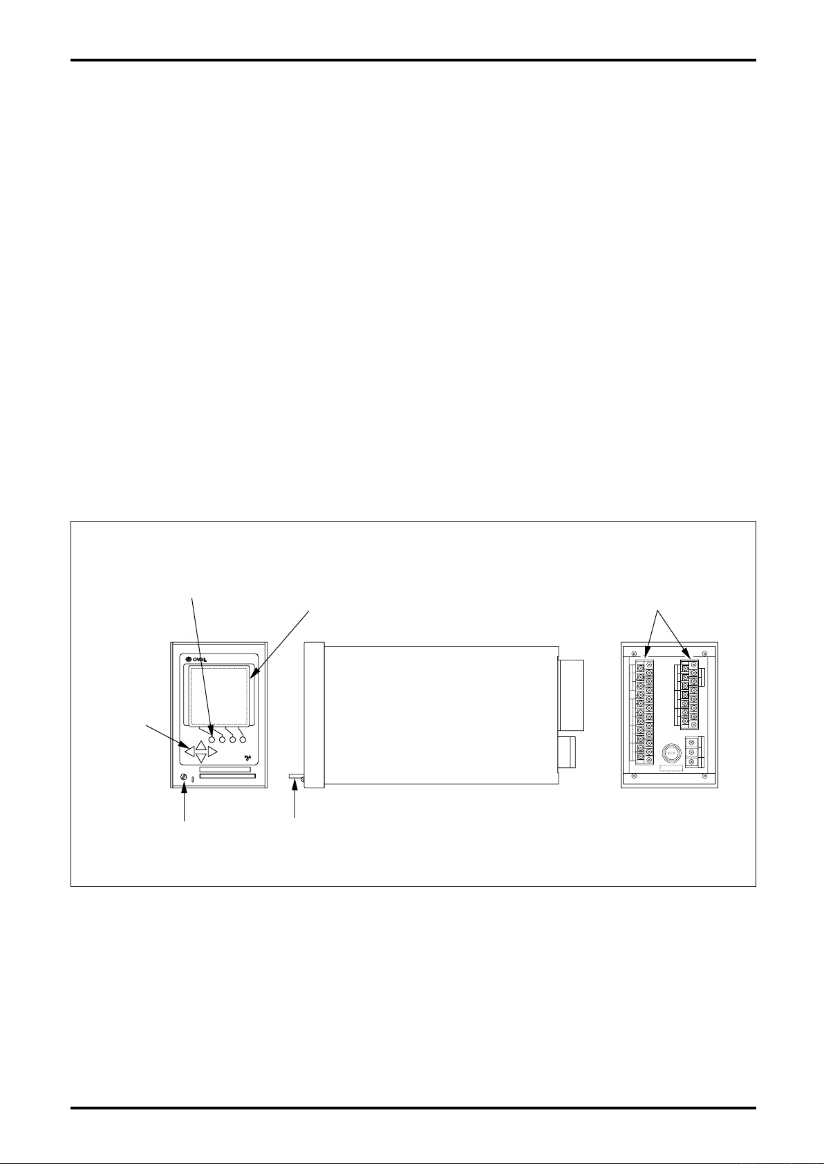
2.2 Part Names and Functions
Function Keys
Display
Shift Keys
Seal Screw
IC Card
Terminal Blocks
Fig. 2.1 Part Names
5
E-887-3N-E
912596
20 232.4
144
136
Min.120
Min.220
92
±0.8
0
+1
138 0
600
1800
450
2200
Optimum
Range
AcceptableRange
Computer
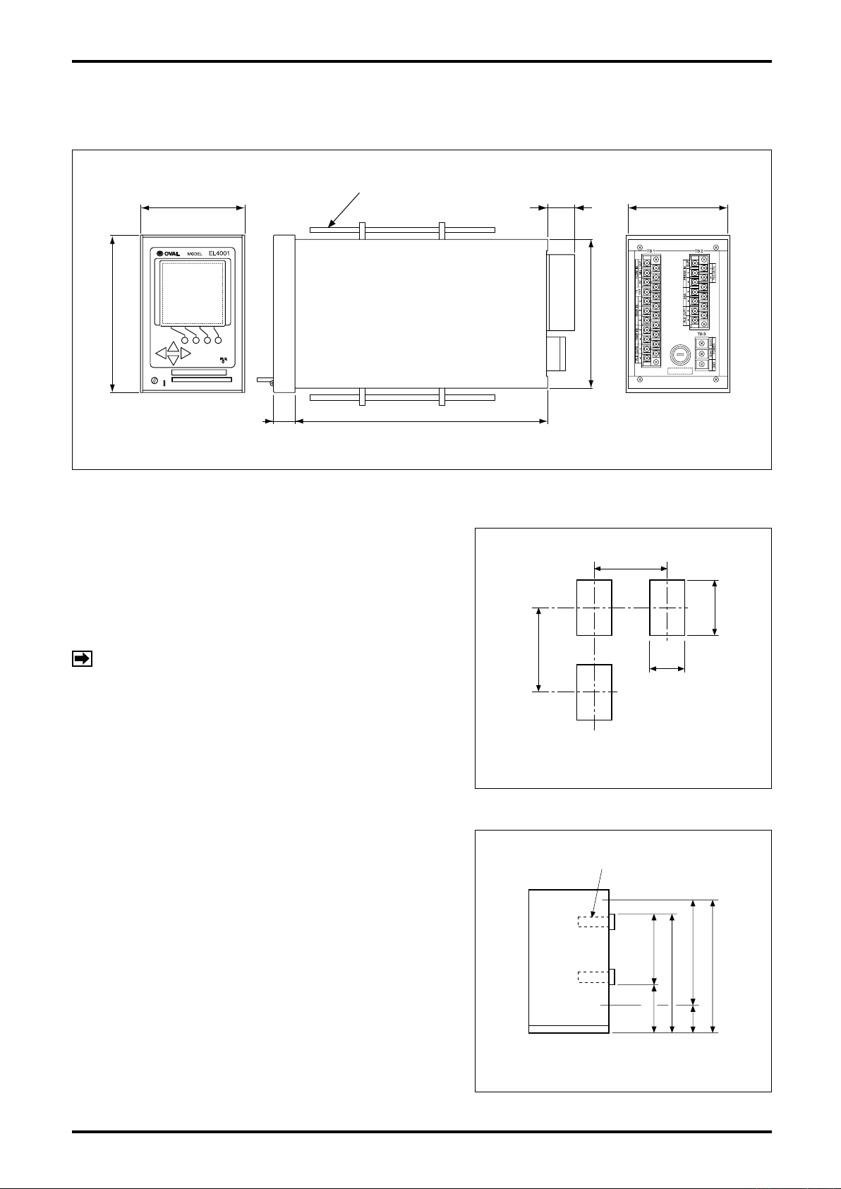
3. INSTALLATION
3.1 Outline Dimensions
All dimensions in millimeters
Hold-down Fitting
Fig. 3.1 Outline Dimensions
3.2 Installation
3.2.1 Installation Location
Select an installation site where:
(1) Mechanical vibration, shock and corrosive gases are
negligible.
(2) Air is dry and temperature at room temperature and
stable.
NOTE: Although the manufacturer guarantees stated
performance at ambient temperatures up to
+50°C, it is recommended that the instrument
be placed in service at room temperature.
(3) Provide a sufficient working space behind the instru-
ment - at least 50 centimeters from the back panel of
the instrument to facilitate wiring and servicing.
3.2.2 Panel
(1) Use a rigid steel sheet with a minimum thickness of
1.6 millimeters. 3.2mm thick is recommended.
(2) If it is required to install instruments alongside each
other, dimensions in Fig. 3.2 are suggested.
(3) Recommended mounting height is given in Fig. 3.3.
Fig. 3.2 Panel Cut
3.2.3 Installation
(1) Front mount the instrument through the cutout in the
panel.
(2) Fit the furnished enclosure hold-down fittings into the
top and bottom slots in the enclosure and, confirming
that the instrument is positioned horizontal, secure
the instrument to the panel with hold-down fittings
(Fig. 3.1).
6
Fig. 3.3 Instrument Mounting Height
 Loading...