

Page 1
Ins. No.
E-026-3-E
SMART COMMUNICATION UNIT
MODEL : EL2310-0DE
□□□
Applicable Flowmeter: Ultrasonic Flowmeter for Liquid
Psonic-L4
For the installation of application software "LinkTop" and the interface
driver, refer to Ins. No. E-020IMC "Smart Communication Unit MODEL:
EL2310 Software Installation Procedure Manual".
1
Page 2

E-026-3-E
2
CONTENTS
1. SMART COMMUNICATION UNIT ............................................................................... 4
1.1 General .................................................................................................................................4
2. BEFORE YOU BEGIN ................................................................................................... 4
2.1 Inspection upon Receipt ......................................................................................................4
2.2 Hookup with Associated Equipment and Devices ...............................................................5
2.3 Communication Interface .....................................................................................................6
3. LinkTop OPERATION ................................................................................................... 7
3.1 LinkTop Screen .....................................................................................................................7
3.2 Starting LinkTop and Connections .......................................................................................8
3.2.1 Starting LinkTop ............................................................................................................................8
3.2.2 Port Setting ................................................................................................................................... 9
3.2.3 Connection .................................................................................................................................. 11
3.3 Terminating the Connection ...............................................................................................13
3.4 Terminating LinkTop ...........................................................................................................14
3.5 Menu: Process Variables (processing values display) ........................................................15
3.5.1 View fld dev vars (processing values measurement) .................................................................. 16
3.5.2 Chart and Recording (chart display and logging) .......................................................................17
3.5.3 Write protect (write status display of transmitter) ....................................................................... 20
3.6 Menu: Setup (settings) .......................................................................................................21
3.6.1 Diameter inside (internal diameter of measuring tube) ...............................................................22
3.6.2 Fld dev vars (transmitter variable) ............................................................................................... 22
3.6.2.1 Flow (parameter setting related to flow rate) ........................................................................22
3.6.2.2 Fluid (parameter setting related to fluid) ............................................................................... 24
3.6.3 Outputs (output setting) .............................................................................................................. 26
3.6.3.1 Pulse output (pulse output setting) ....................................................................................... 26
3.6.3.2 Status output (status output setting) ....................................................................................27
3.6.4 Device information (transmitter information setting) ................................................................... 29
3.7 Menu: Diag / Service (check / adjustment) ........................................................................31
3.7.1 Loop Test (loop test).................................................................................................................... 32
3.7.1.1 Fix Analog (analog output loop test) ..................................................................................... 32
3.7.1.2 Fix Pulse (pulse output loop test).......................................................................................... 34
3.7.1.3 Fix Flow (simulated flow rate loop test) ................................................................................35
3.7.2 Calibration (transmitter's adjustment function) ........................................................................... 37
3.7.2.1 Auto zero (auto zero point adjustment) ................................................................................. 37
3.7.2.2 Init AGC (sensitivity adjustment) ........................................................................................... 39
3.7.3 Trim Analog (analog output adjustment) ..................................................................................... 41
3.7.4 Totalizer cntrl (cumulative total control) ...................................................................................... 44
Page 3
E-026-3-E
3.8 Menu: Maintenance (maintenance) .................................................................................... 45
3.8.1 Device reset (transmitter reset) ................................................................................................... 46
3.9 Menu: Window (window) ....................................................................................................47
3.10 Menu: File (file) .................................................................................................................49
3.10.1 Database ................................................................................................................................... 49
3.10.1.1 Opening Files ...................................................................................................................... 49
3.10.1.2 Saving Files ......................................................................................................................... 50
3.10.1.3 Deleting Files .......................................................................................................................51
3.10.1.4 Downloading ....................................................................................................................... 52
3.10.2 Printing ...................................................................................................................................... 55
3.11 Troubleshooting ................................................................................................................57
3.11.1 If There is No Response ............................................................................................................ 57
3.11.2 If It is Not Possible to Connect to the Flowmeter ..................................................................... 57
3.11.3 Input Errors ...............................................................................................................................58
3.11.4 Error, Status Display List ........................................................................................................... 59
4. PRODUCT CODE EXPLANATION ............................................................................. 60
5. GENERAL SPECIFICATIONS ..................................................................................... 61
This manual uses the precaution words "NOTE", "CAUTION", and "WARNING" as explained
below:
NOTE: Notes are separated from the general text to bring the user's attention to
important information.
CAUTION: Caution statements inform the user of hazards or unsafe practices which could
result in minor personal injury or product/property damage.
WARNING: Warning statements inform the user of hazards or unsafe practices which could
result in severe personal injury or death.
3
Page 4
E-026-3-E
4
1
Ins. No.
E-020IMC-1-E
MODEL : EL2310
SMART COMMUNICATION UNIT
SOFTWARE INSTALLATION
PROCEDURE MANUAL
MODEL : EL2310-0DE
□□□
Applicable Flowmeter: Ultrasonic Flowmeter for Liquid
Psonic-L4
SMART COMMUNICATION UNIT
For the installation of application software "LinkTop" and the interface
driver, refer to Ins. No. E-020IMC "Smart Communication Unit MODEL:
EL2310 Software Installation Procedure Manual".
Ins. No.
E-026-1-E
1
1. SMART COMMUNICATION UNIT
1.1 General
Described in this manual are the operating instructions to use the application software LinkTop® of the
®
Smart Communication Unit which operates in the Microsoft operating system Windows
®
LinkTop
is a communication terminal designed for use in combination with a personal computer
(hereinafter referred to as PC) and any one of the OVAL ultrasonic flowmeters to set up, alter, adjust, or
read out parameters and variables, through interactive communications, either on-site or from remote
locations.
®
Using a Windows
It is necessary to install the application software LinkTop
PC at hand, it is possible to monitor multiple windows on its screen.
®
in your PC before connecting the communica-
tion interface (*) between the PC and the flowmeter.
NOTE: In case of Bell202 communication: Bell202 communication interface of OVAL smart
communication unit EL2310 is necessary.
environment.
2. BEFORE YOU BEGIN
2.1 Inspection upon Receipt
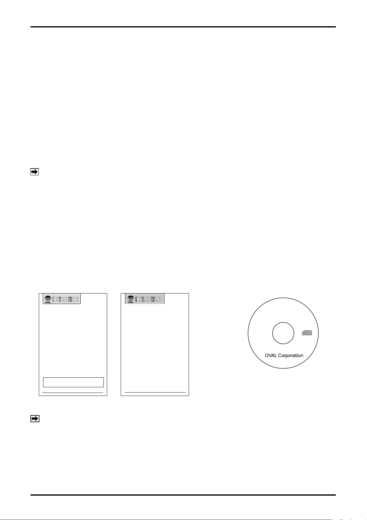
Be sure you have the following items.
Open the product package and make sure you have all the components required.
Instruction Manual 1
(This manual)
Instruction Manual 2
(Software Installation Procedure Manual)
CD-ROM
(Application software LinkTop®)
Communication interface
(in case of product with interface)
(for Bell202 communication Fig. 2-2)
LinkTop
®
for Psonic-L4
®
NOTE: For the installation of the application software "LinkTop®" and the interface driver software (*),
*:
refer to "Installation Procedure Manual".
The driver software in the CD-ROM is intended for an application of Bell202 Communication
Interface for OVAL Smart Communication Unit EL2310.
Page 5
E-026-3-E
2.2 Hookup with Associated Equipment and Devices
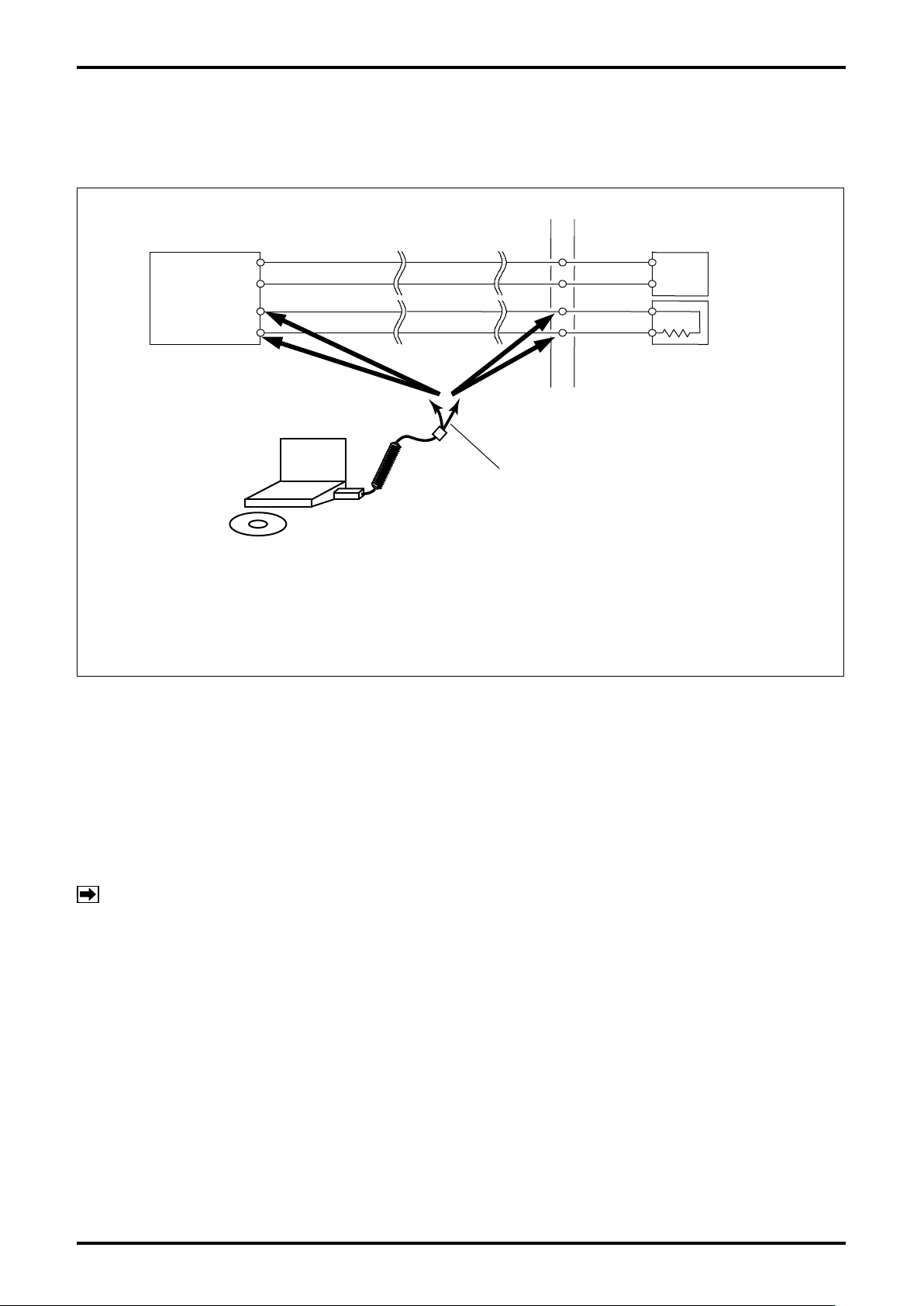
Equipment set-up with associated equipment and devices is shown in Fig. 2-1. (Prepare a PC by yourself.)
Relay terminal block
Power
supply
+
R
L
−
Receiving instrument
built-in)
L
Flowmeter
transmitter
OVAL ultrasonic flowmeter
Application software
+
(LinkTop
LINE/+
NEUT/-
4 to 20mADC
−
®
)
Connected
point
Bell202 communication
interface
LINE/+
NEUT/−
(load resistance R
Probe
Polarity observation is not required.
Connect the probes across + and - terminals
of analog output.
The receiving instrument in this figure requires a load resistance 250Ω min. Its upper limit depends on the
specification of the transmitter in use.
If the receiving instrument does not have a built-in R
, an external RL needs to be connected in series.
L
Fig. 2-1
- Procedure of connection -
(1) Connect the cables as shown in Fig. 2-1.
(2) Turn ON the power supply of PC and activate LinkTop for Psonic-L4.
(3) Turn ON the power supply of flowmeter.
* Before connecting the communication cable to the flowmeter transmitter, turn OFF the power supply of
flowmeter.
NOTE: In Fig. 2-1, the customer is to supply a PC that meets the following requirements:
¯
OS: Windows XP, Windows Vista, Windows 7 to 10
¯
RAM: 256MB or larger
¯
Hard disk: 10MB or larger free space
¯
USB port that is suitable for connecting to the communication interface to be used shall
be provided. A USB port is required when using Bell202 communication interface for OVAL
Smart Communication Unit EL2310.
5
Page 6
E-026-3-E
6
2.3 Communication Interface
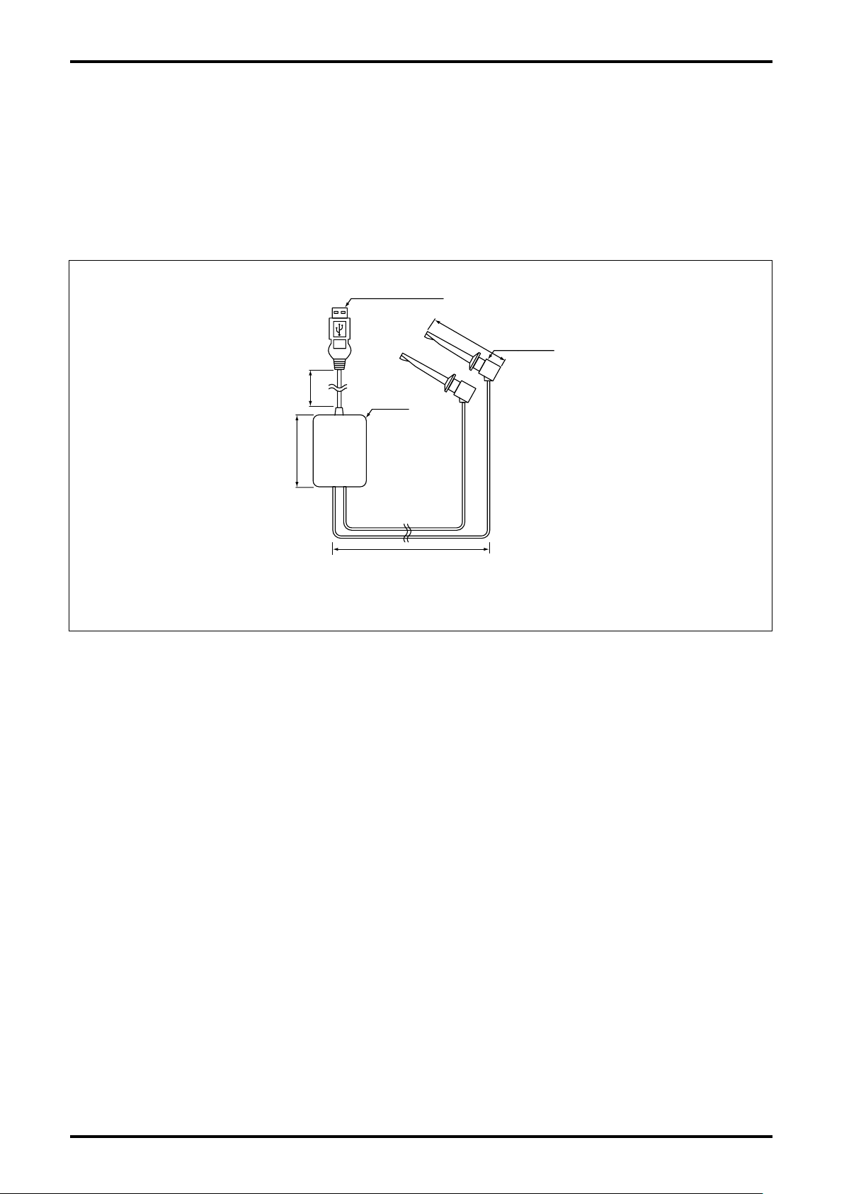
A signal transmitter is provided for the communication signal conversion between the external serial port
(COM port) of the PC and the flowmeter.
When using Bell202 communication, the Bell202 communication interface for OVAL smart communication
unit EL2310 shall be used. The signal transmitter consists of the components shown in Fig. 2-2.
connector
Approx. 1000
Cable length from
50
USB connector
(60)
Body
Cable length from probe
Approx. 500
Fig. 2-2
Unit: mm
Probe
Page 7
3. LinkTop OPERATION
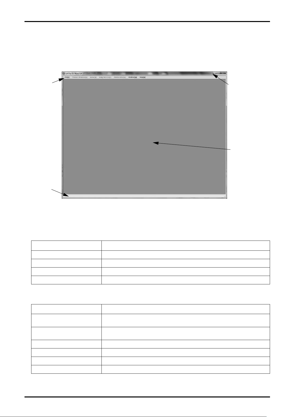
3.1 LinkTop Screen
(1) Fig. 3-1 shows what the LinkTop window looks like.
E-026-3-E
Menu
Communication
status display bar
Fig. 3-1
Title bar
Message
box field
(2) "Communication status display bar" displays the communication status of PC and flowmeter. The
description on "communication status display bar" is shown in the table below.
Display item Details
SEND At communications (when sending data)
RECV WAIT At communications (when waiting for receiving data)
IDLE When communications are interrupted
CLOSE When communications are disconnected
The overview of each menu is shown in the table below.
(3)
Display item Details
File
Process Variables
Setting of communication connection and construction of database
(refer to section 3)
Checks the measurement status with numeric values (refer to section
3.5)
Setup Sets the transmitter parameter(refer to section 3.6)
Diag / Service Check and adjustment of transmitter (refer to section 3.7)
Maintenance Reset of transmitter (refer to section 3.8)
Window Arrays displayed windows (refer to section 3.9)
7
Page 8
E-026-3-E
8
3.2 Starting LinkTop and Connections
3.2.1 Starting LinkTop
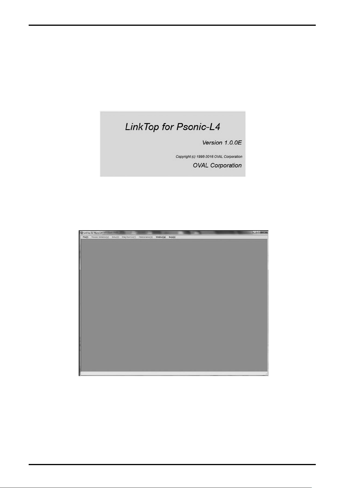
(1) To initiate LinkTop, click "Start" at the bottom left of the PC screen, and then click "LinkTop for
Psonic-L4 (E) Ver1.0.0" in "Program".
The following window (Fig. 3-2) will be displayed and it is possible to verify the version of the
(2)
software.
Fig. 3-2
(3) After the window shown in Fig. 3-2 is displayed for a few seconds, the main window (Fig. 3-3) will be
displayed.
Fig. 3-3
Page 9
3.2.2 Port Setting
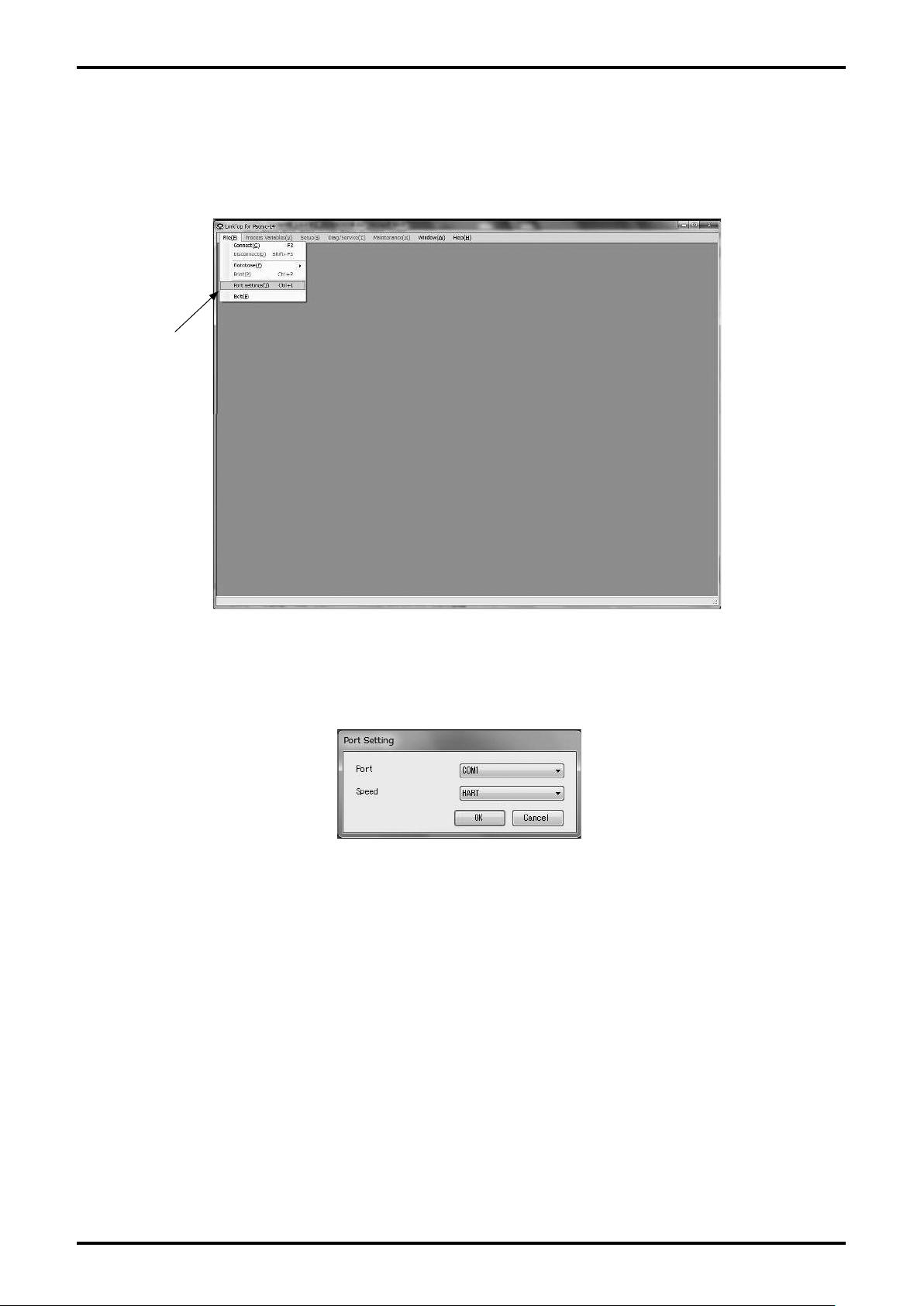
It is possible to change the setting of serial port of PC.
(1) Click "File (F)" from the menu, and then click on "Port Setting (I) Ctrl+I".
Click here.
E-026-3-E
Fig. 3-4
(2) The following window (Fig. 3-5) will be displayed. Here, select the serial port of PC.
Fig. 3-5
9
Page 10
E-026-3-E
10
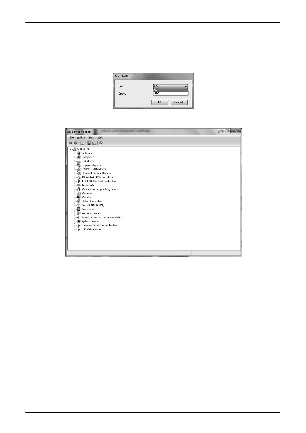
(3) Click the arrow on right side as shown in Fig. 3-6, and select the port for which connection is
changed from the drop-down list.
is possible to check whether the port is connected or not with the device manager screen shown in
It
Fig. 3-7.
Fig. 3-6
Fig. 3-7
(4) After the selection is completed, click "OK" button. After clicking the button, the value will be
changed to the setting value you select and the window will disappear.
If you want to cancel the setting, click "Cancel" button.
The standard setting is "COM1".
(5)
* When USB serial port is used, select "COM (port number) (USB)".
* When USB serial port is used, set up the included driver preliminarily and use it in connectable status.
For the setting of communication speed, select "HART".
(6)
Page 11
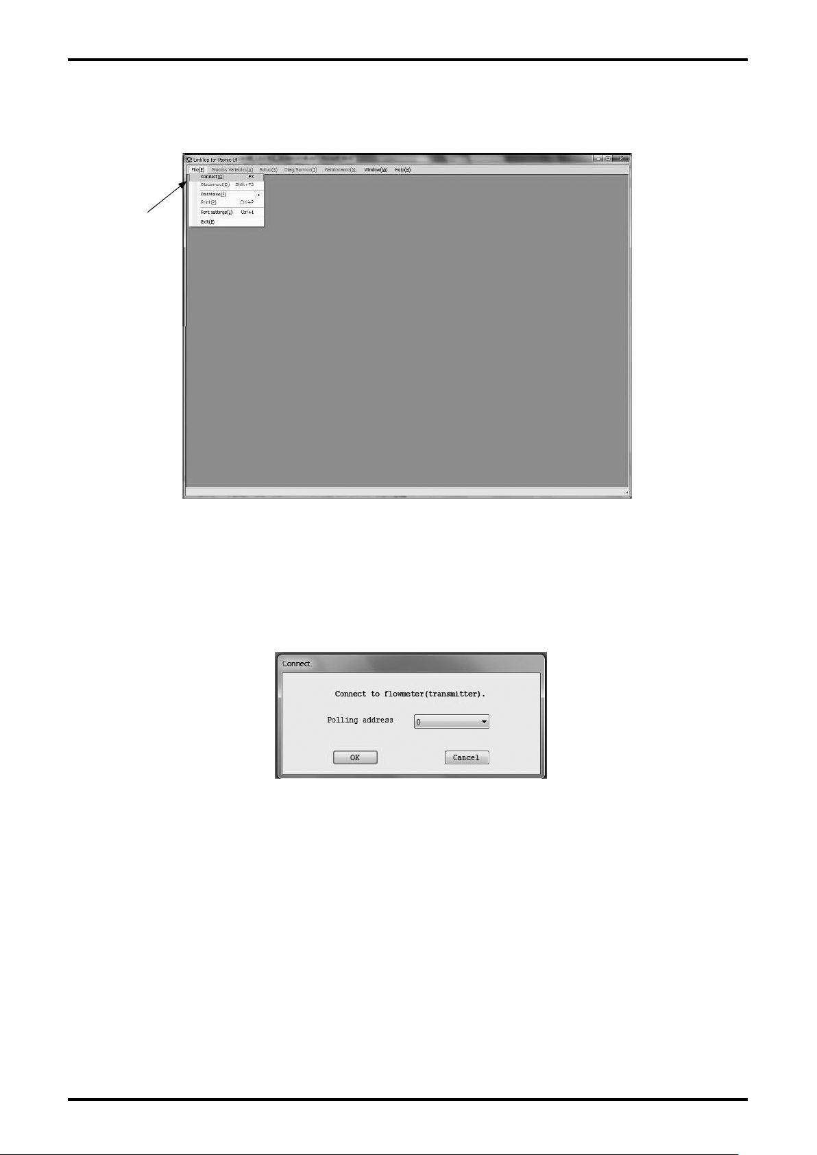
3.2.3 Connection
Click "File (F)" from the menu, and then click on "Connect (C) F3".
(1)
Click here.
E-026-3-E
Fig. 3-8
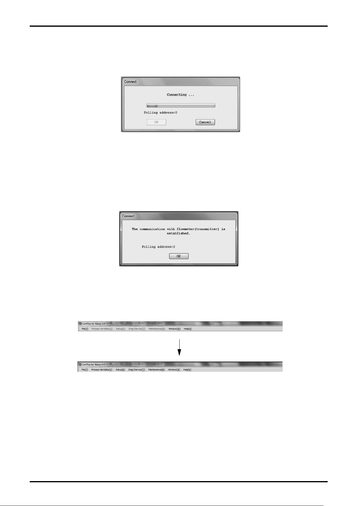
(2) The message box (Fig. 3-9) will be displayed. By clicking "OK" button, the connection will be started.
By clicking "Cancel" button, the connection operation will be cancelled.
The polling addr
ess is set to "0" when the product is shipped from factory.
Fig. 3-9
11
Page 12
E-026-3-E
12
(3) Click "OK" button in the message box to start the connection. Then, the following window (Fig. 3-10)
will be displayed. It is possible to check the connection status with the progress bar in the center of
window.
Fig. 3-10
The display of "communication status display bar" switches between "SEND" and "RECV WAIT". By
clicking "Cancel" button, the connection will be cancelled.
If the connection is completed, the following message box (Fig. 3-11) will be displayed. Click "OK"
(4)
button.
Fig. 3-11
(5) When the connection is completed, some functions of the menu will become selectable (color of
characters will change to black) as shown in Fig. 3-12.
Fig. 3-12
Page 13
E-026-3-E
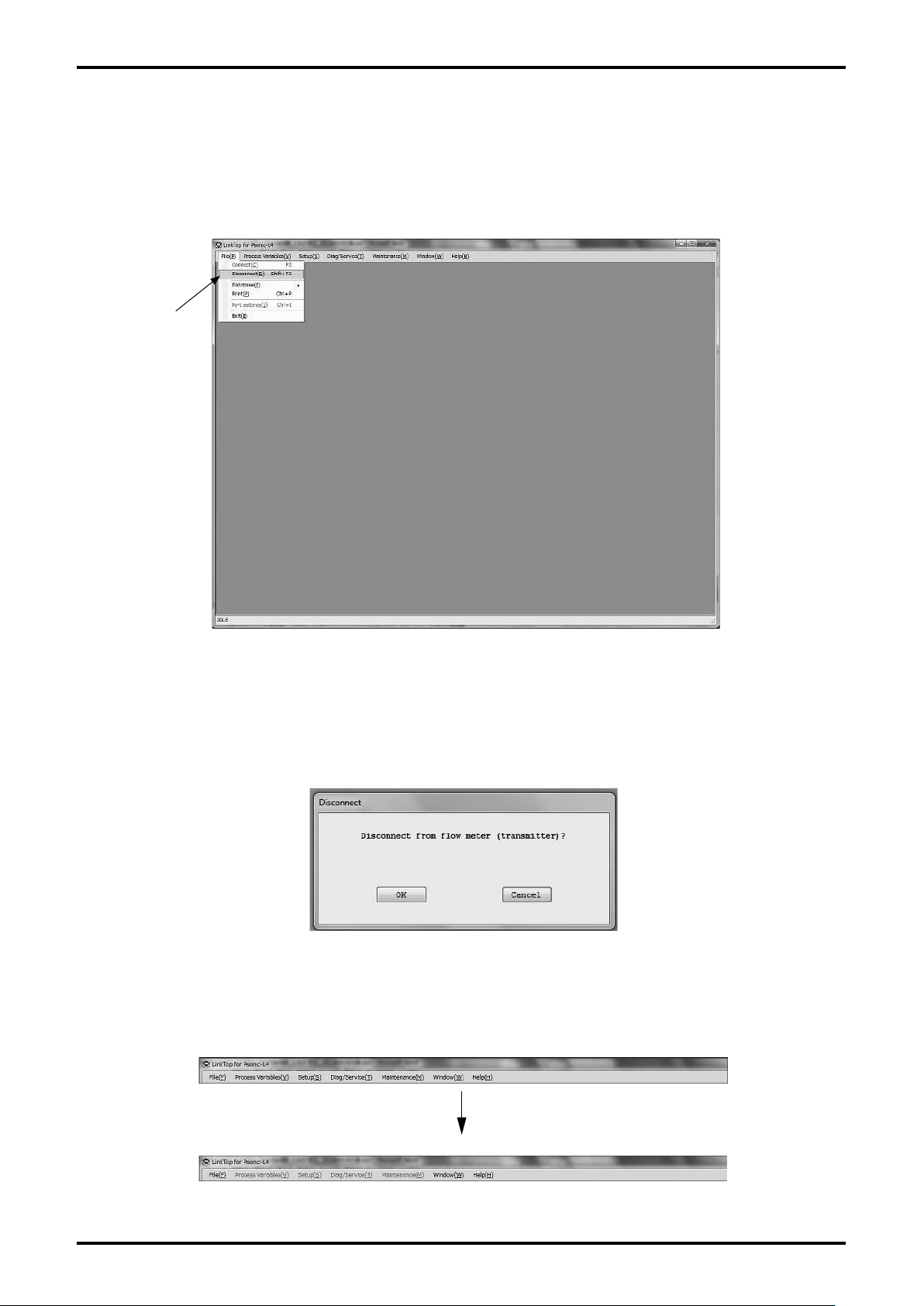
3.3 Terminating the Connection
To terminate connection between the flowmeter transmitter and LinkTop, follow the procedure given
below:
Click "File (F)" from the menu, and then click on "Disconnect (D) Shift+F3".
(1)
Click here.
Fig. 3-13
(2) The message box (Fig. 3-14) will be displayed. By clicking "OK" button, the connection between
flowmeter and LinkTop will be terminated.
By clicking "Cancel" button, the connection termination operation will be cancelled.
Fig. 3-14
(3) When connection is terminated, some functions of the menu become inactive (characters will change
to white) as shown in Fig. 3-15.
Fig. 3-15
13
Page 14
E-026-3-E
14
3.4 Terminating LinkTop
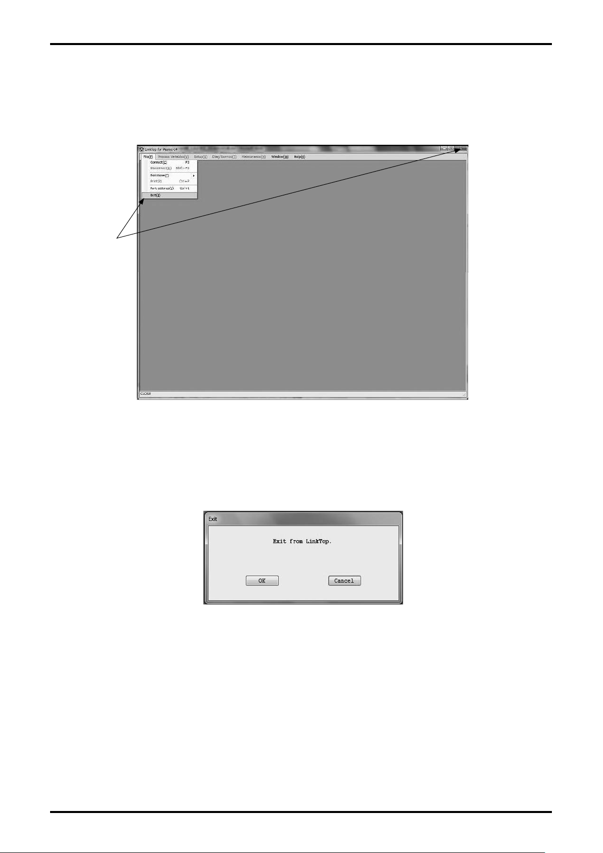
(1) To exit LinkTop, click "File (F)" from the menu and select "Exit (E)" or click "Close" button in the upper
right of the screen.
Click here.
Fig. 3-16
(2) The message box (Fig. 3-17) will be displayed. To exit LinkTop, click "OK" button. Click "OK"
to confirm and the application software window will disappear from the desktop. To abort the
terminating process, click on "Cancel" button.
Fig. 3-17
Page 15
E-026-3-E
3.5 Menu: Process Variables (processing values display)
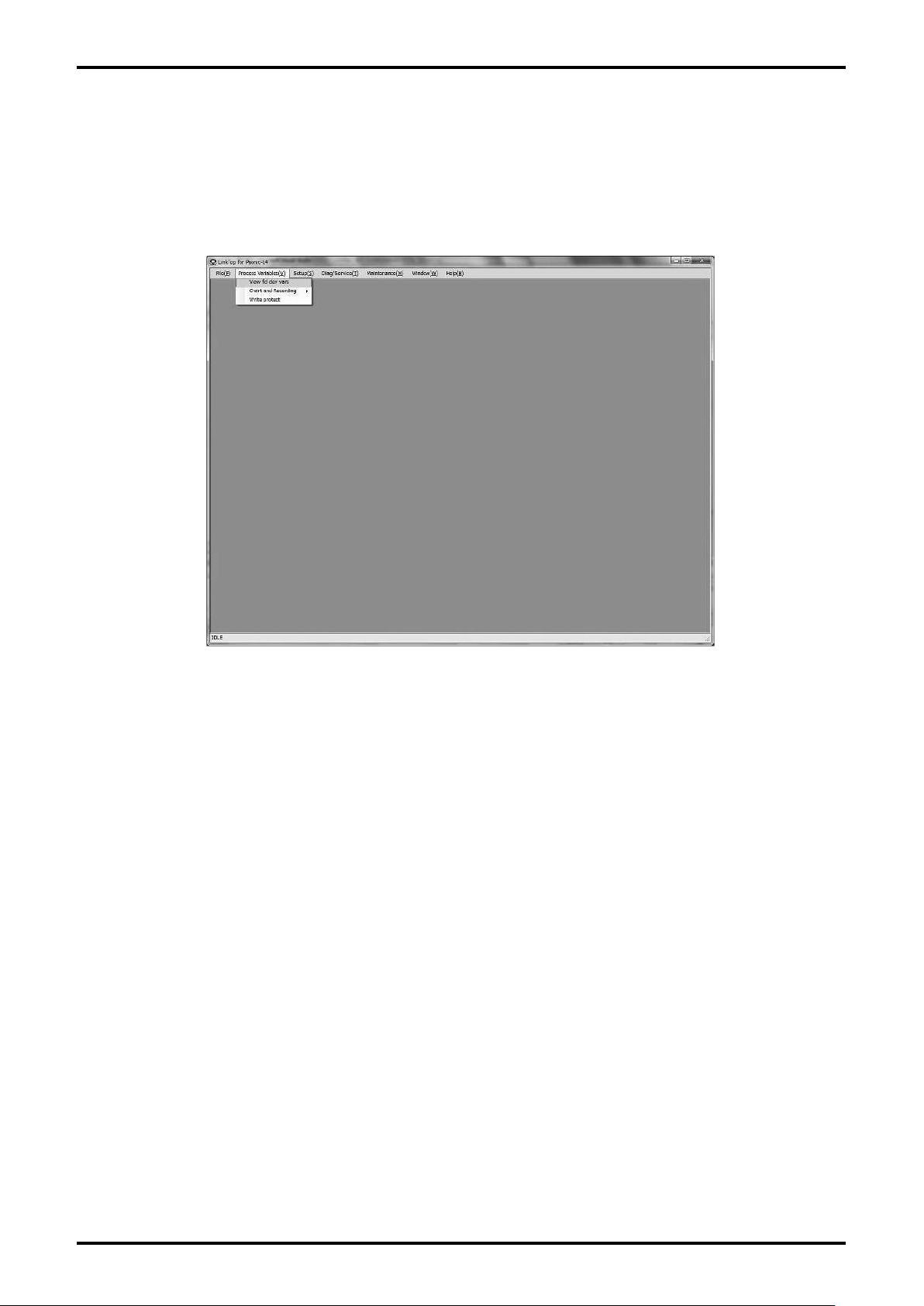
The "Process Variables" menu can be used to confirm process value of flowmeter (instantaneous flow
rate, flow velocity, cumulative total in positive direction, cumulative total in opposite direction, analog
output, Gain1 to 4), chart display, logging, and status of write protect.
Fig. 3-18 shows what the actual screen looks like.
Fig. 3-18
15
Page 16
E-026-3-E
16
3.5.1 View fld dev vars (processing values measurement)
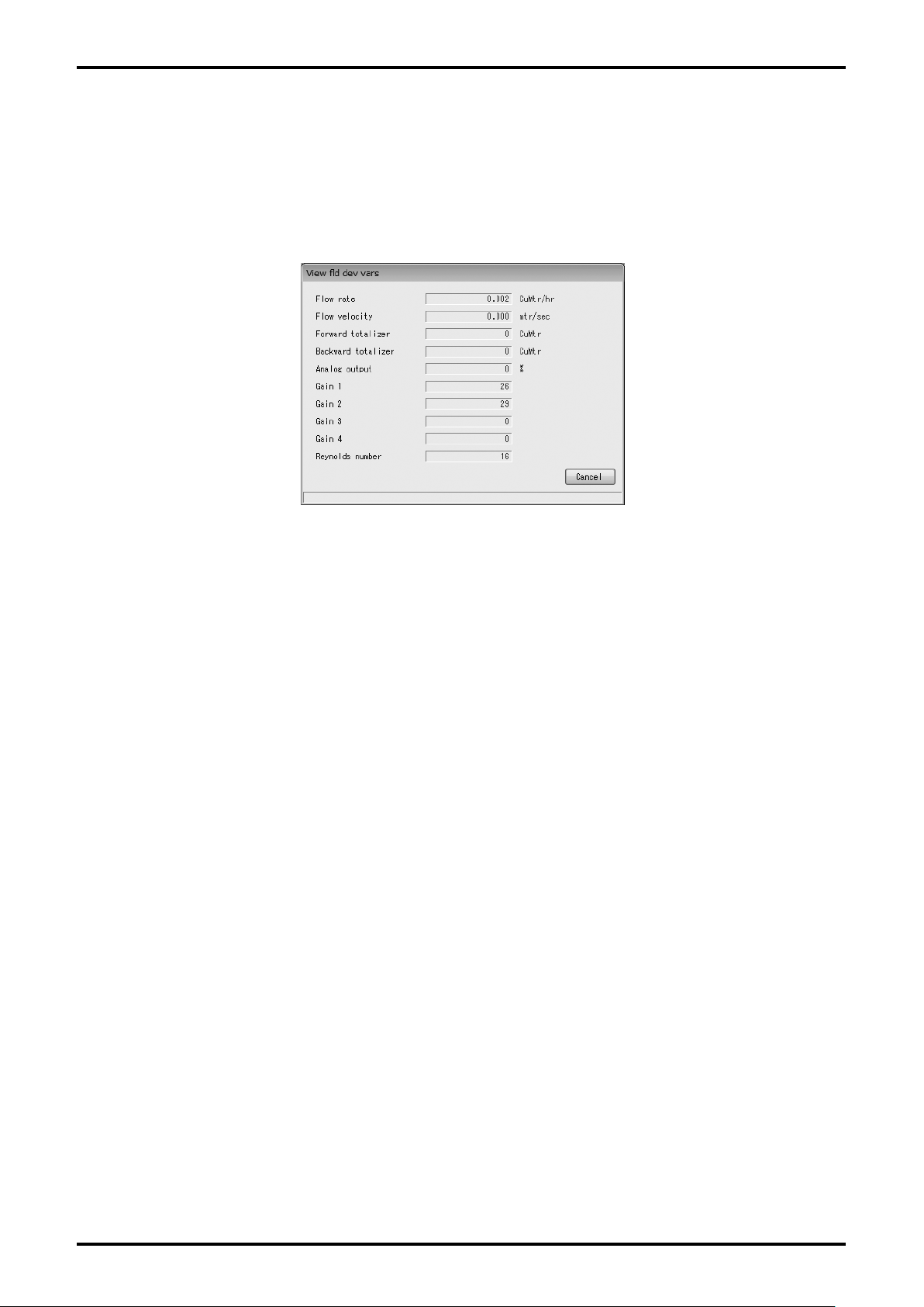
(1) Click "Process Variables (V)" from the menu in the upper prat of the screen, and then click on "View
fld dev vars".
The following window (Fig. 3-19) will be displayed.
(2)
Fig. 3-19
"Flow rate" ... instantaneous flow rate
"Flow velocity" ... flow velocity
"Forward totalizer" ... cumulative total (positive direction)
"Backward totalizer" ... cumulative total (opposite direction)
"Analog output" ... analog % flow rate
"Gain 1" ... gain value (pass 1)
"Gain 2" ... gain value (pass 2)
"Gain 3" ... gain value (pass 3)
"Gain 4" ... gain value (pass 4)
"Reynolds number" ... Reynolds number
If there is a problem with the flowmeter transmitter, then an error message will be displayed in the
(3)
window under the process value measurement window. For details, refer to section 3.11.4 "Error,
Status Display List".
To exit the process value measurement window, click "Cancel" button.
(4)
Page 17
E-026-3-E
3.5.2 Chart and Recording (chart display and logging)
Display of flow rate, flow velocity, gain value of sensor as well as data logging can be carried out.
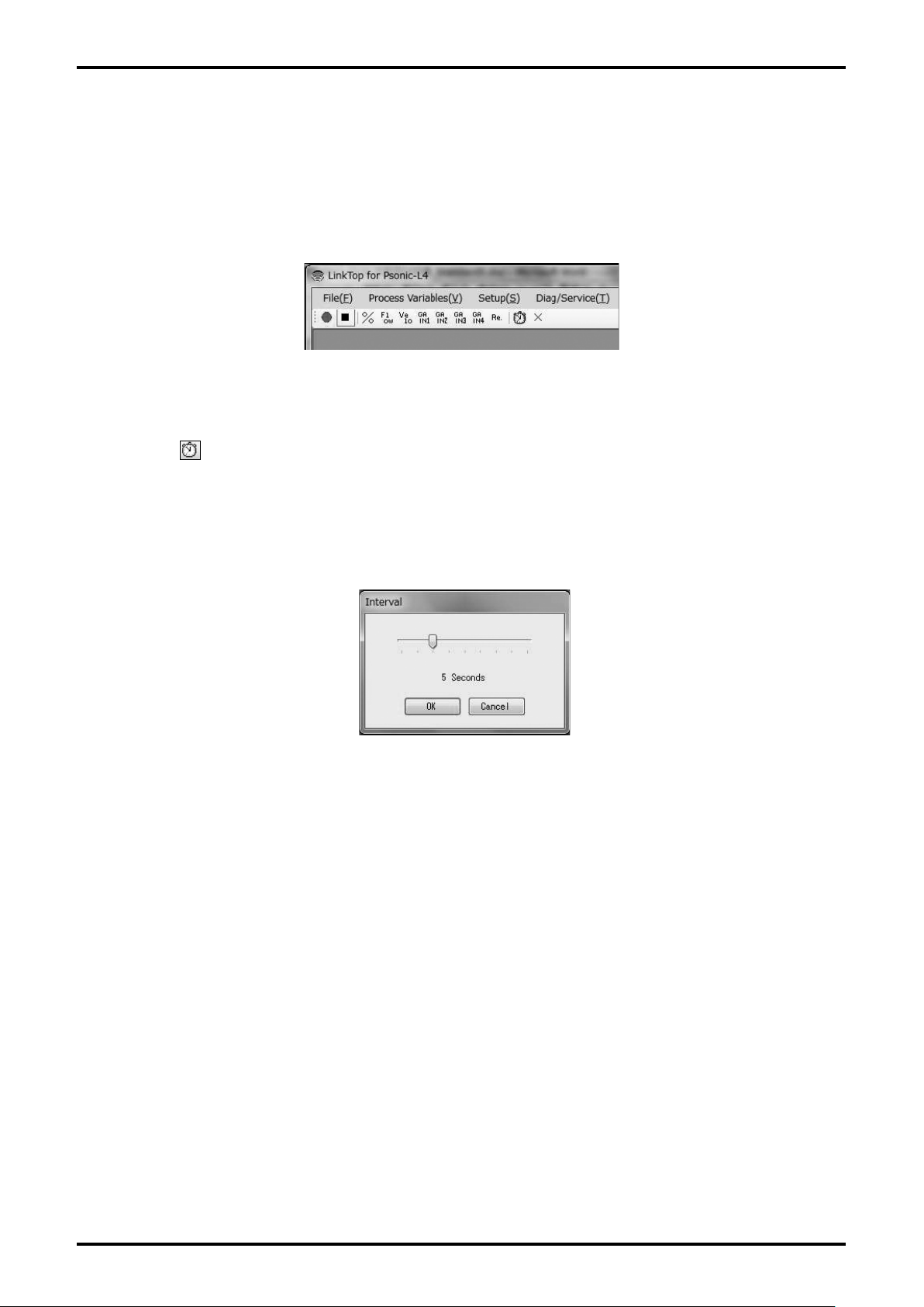
(1) Click "Chart and Recording" from the menu in the upper part of the screen, and select "Active", then
a tool bar as shown in Fig. 3-20 will be displayed underneath the menu.
Fig. 3-20
(2) Click the button on the tool bar or "Chart and Recording" - "Interval" from the menu, then the
window shown in Fig. 3-21 will be displayed, enabling setting of update interval of chart display and
logging interval.
Select
"1 Minute", "5 Minutes", "10 Minutes", and "1 Hour" and click "OK" button.
the preferred interval from "1 Second", "3 Second", "5 Second", "10 Second", "30 Second",
Fig. 3-21
17
Page 18
E-026-3-E
18
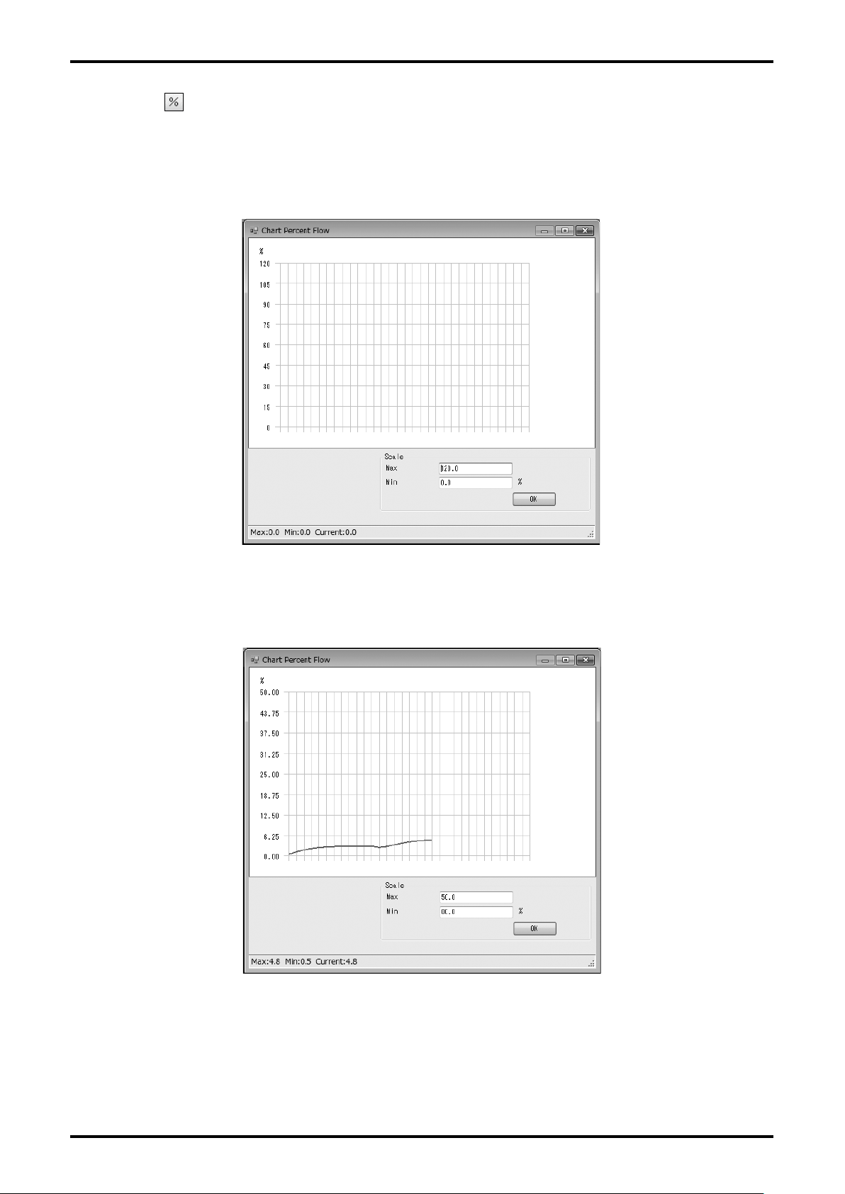
(3) Click the button on the tool bar or "Chart and Recording" - "Chart" - "Percent Flow" from the
menu, then the window shown in Fig. 3-22 will be displayed, enabling chart display of percent flow.
W
hen changing the scale of the vertical axis, enter the preferred values to "Max" and "Min" in "Scale",
then click "OK" button.
Fig. 3-22
(4) A chart is drawn at the intervals of update set in (2).
Fig. 3-23
Page 19
E-026-3-E
(5) To hide the chart, click the button on the tool bar or "Chart and Recording" - "Chart" - "Percent
Flow" from the menu.
(6)
Similarly, by clicking the
from the menu, instantaneous flow rate can be shown or hidden. If you click the
bar or "Chart and Recording" - "Chart" - "Flow Velocity" from the menu, the flow velocity chart can be
shown or hidden as well. The gain value (passes 1 to 4) and Reynolds number are operated in a same
way.
If you click the
(7)
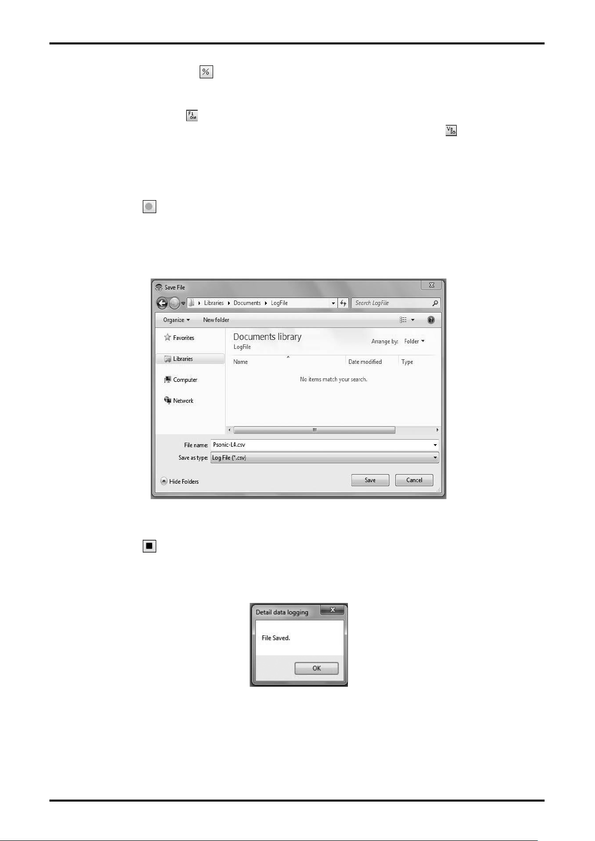
menu, the following dialog box (Fig. 3-24) will be displayed. Select the disk and folder to create a file,
enter a file name, and click "Save (S)" button.
A CSV file is cr
button on the tool bar or "Chart and Recording" - "Recording" - "Start" from the
eated and data logging begins.
button on the tool bar or "Chart and Recording" - "Chart" - "Flow Rate"
button on the tool
Fig. 3-24
(8) If you click the button on the tool bar or "Chart and Recording" - "Recording" - "Stop" from the
menu, the logging will stop (terminating the writing process on the file) and the file will be completed.
Then the following message box (Fig. 3-25) will be displayed. Click "OK" button.
Fig. 3-25
19
Page 20
E-026-3-E
20
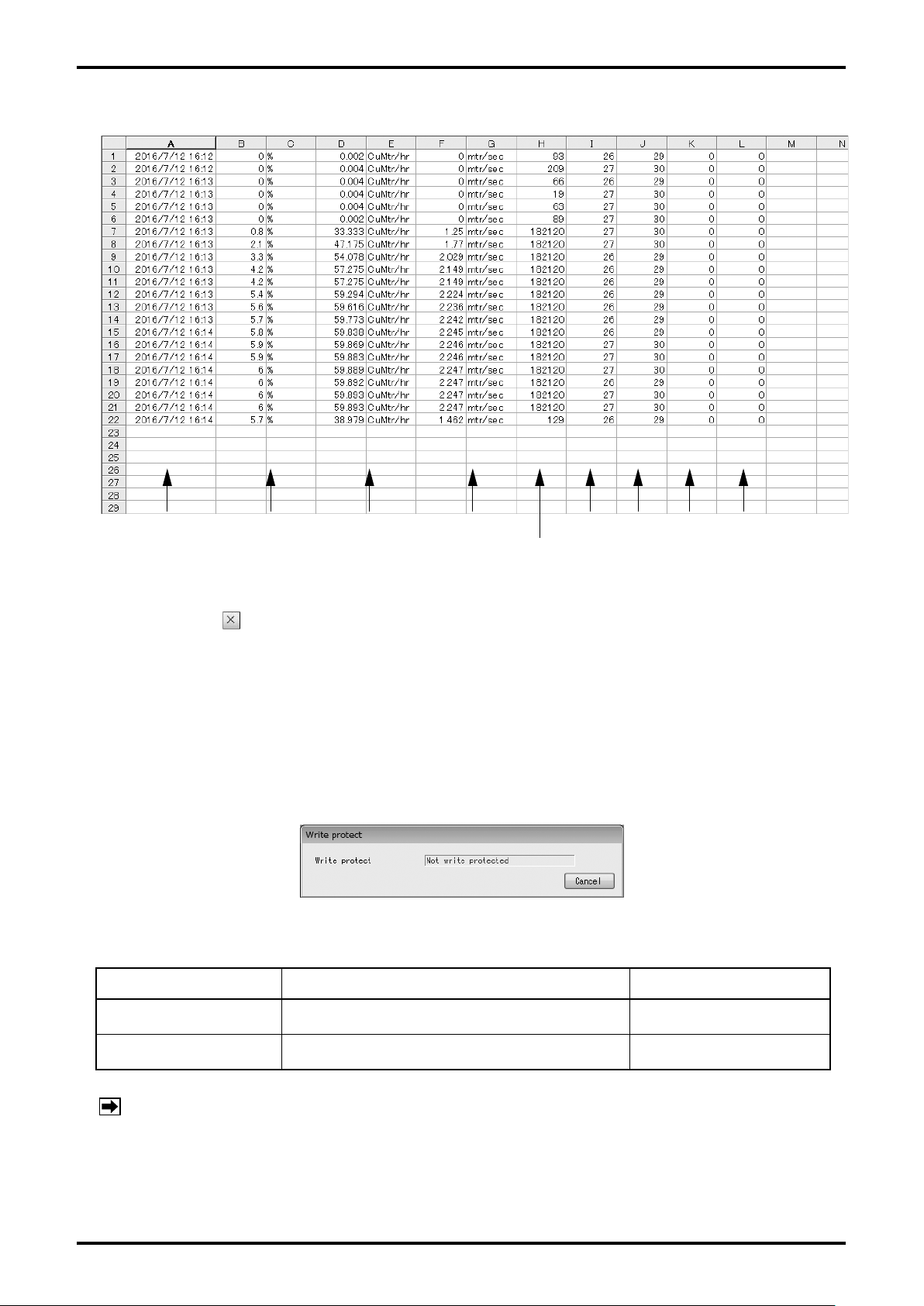
(9) The content of the log file when logging interval is set to "5 Seconds" is as shown in Fig. 3-26.
Date Percent flow Flow rate Flow velocity Gain 3 Gain 4Gain 2Gain 1
Reynolds number
Fig. 3-26
(10) If you click the button on the tool bar or "Chart and Recording" - "Active" from the menu, chart
display and data logging will be terminated.
3.5.3 Write protect (write status display of transmitter)
Whether the parameter of transmitter can be changed or not is displayed.
(1) Click "Process Variables(V)" in the upper part of the screen, and then click on "Write protect". Then,
the following window (Fig. 3-27) will be displayed.
Fig. 3-27
"W
rite protect" shows whether parameter change of the transmitter is available or not.
Mode Detail SW (S1-LCK) setting
Not write protected Enables changing and setting parameters. OFF
Write protected Disables changing and setting parameters. ON
NOTE: Selecting the above mode is available by changing switches S1-LCK on the CPU board
of the flowmeter transmitter.
(2)
To exit this procedure, click "Cancel" button.
Page 21
E-026-3-E
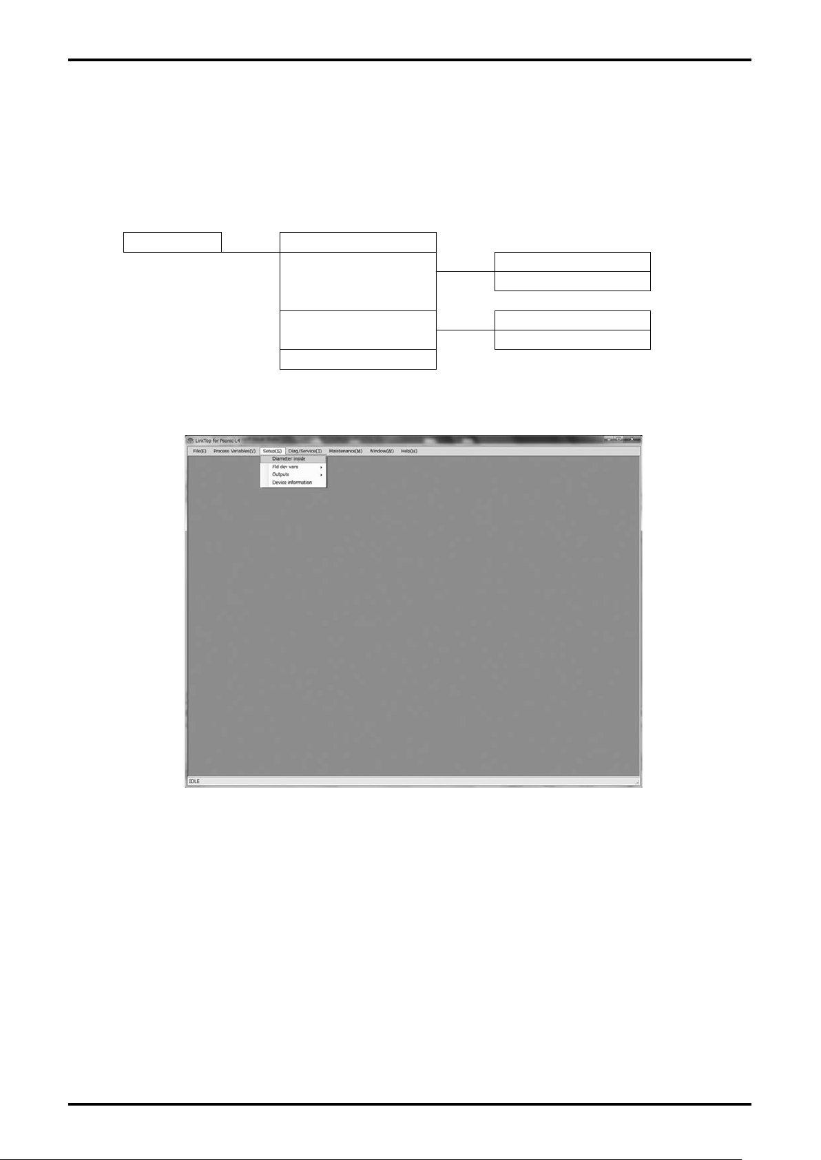
3.6 Menu: Setup (settings)
The "Setup" menu can be used to set flowmeter's various parameter values, transmitter's information,
and so on.
If windows of "Diag/Service" menu are displayed on the screen, then it will not be possible to set the
various parameters, transmitter information, and so on. Close these windows before making settings.
For the actual screen, refer to Fig. 3-28.
Setup Diameter inside
Flow
Fld dev vars
Fluid
Outputs
Device information
Setup Item Tree
Pulse output
Status output
Fig. 3-28
21
Page 22
E-026-3-E
22
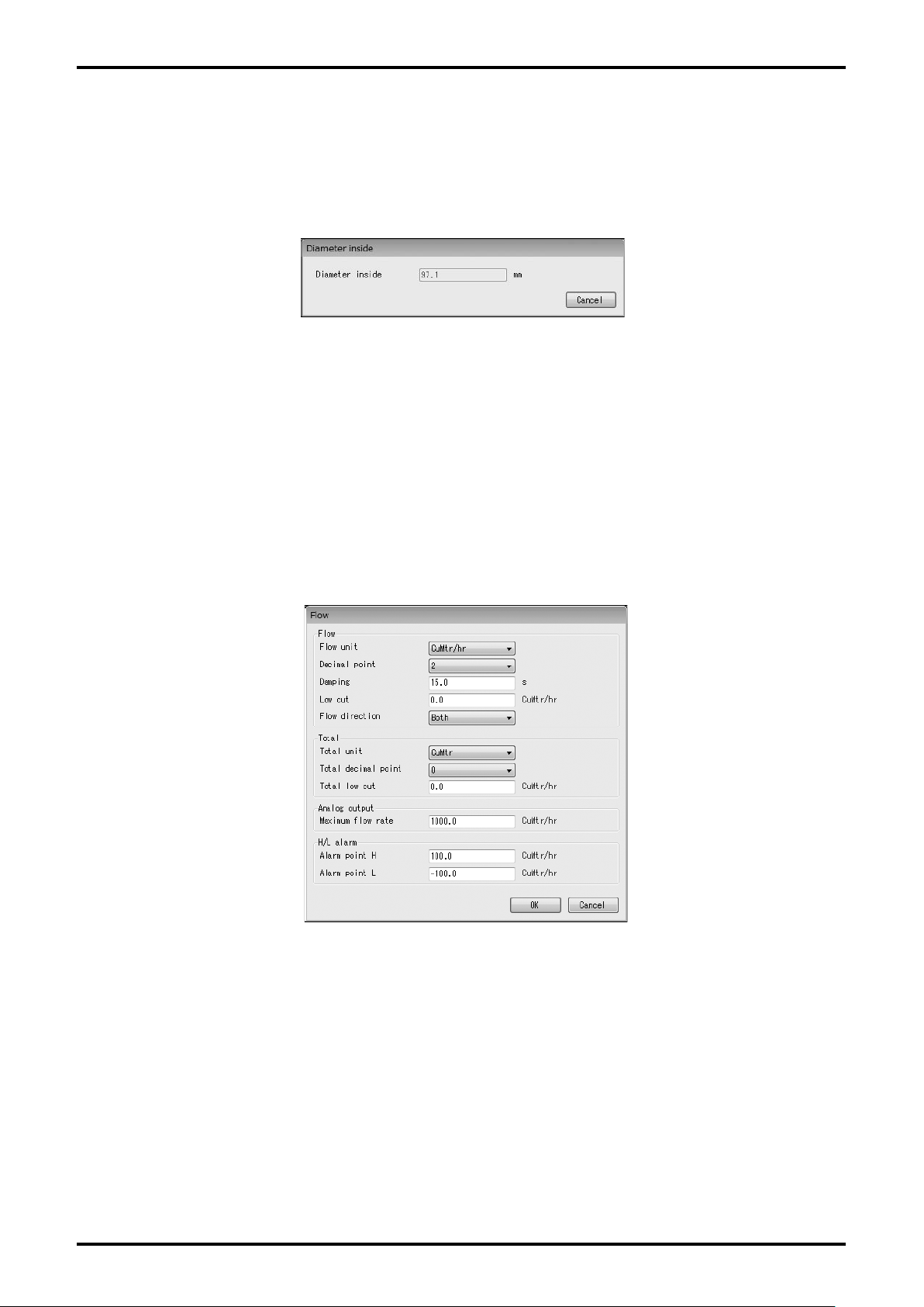
3.6.1 Diameter inside (internal diameter of measuring tube)
(1) Click "Setup (S)" from the menu, and then click on "Diameter inside".
(2) The following window (Fig. 3-29) will be displayed. Here, it is possible to check the internal diameter
of measuring tube.
Fig. 3-29
(3) After the confirmation is completed, click "Cancel" button to close the item window.
3.6.2 Fld dev vars (transmitter variable)
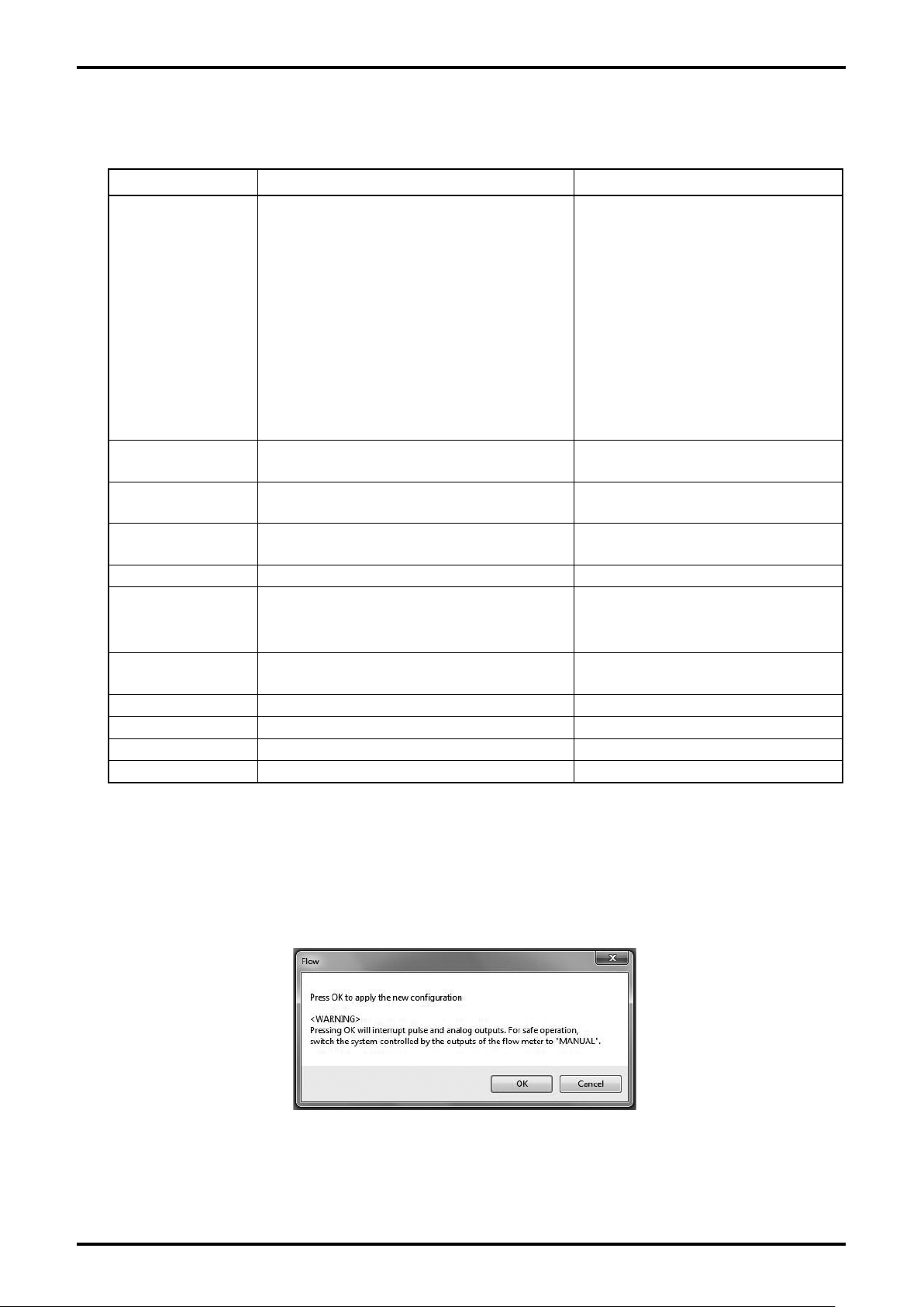
3.6.2.1 Flow (parameter setting related to flow rate)
(1) Click "Setup (S)" from the menu, and then click on "Flow" from the drop-down list of "Fld dev vars".
(2) The following window (Fig. 3-30) will be displayed.
Fig. 3-30
Page 23
E-026-3-E
(3) Select each item and enter a value. To change the unit, it is also necessary to change the value of
low-cut and so on.
Setting item Detail Setting range
CuMtr/day, CuMtr/hr, CuMtr/min,
CuMtr/sec, liter/hr, liter/min, liter/sec,
CuFt/day, CuFt/hr, CuFt/min, CuFt/
sec, gal/day, gal/hr, gal/min, gal/sec,
ImpGal/day, ImpGal/hr, ImpGal/min,
Flow unit Unit of instantaneous flow rate
Decimal point
Damping
Low cut
Flow direction Inflow direction (measurement mode) Forward Flow, Reverse Flow, Both
Total unit Totalization unit
Total decimal point
Total low cut Low-cut (for Totalization) 0.0 to 9999.0 (flow rate setting unit)
Maximum flow rate Full-scale flow rate 0.0 to 9999.0 (flow rate setting unit)
Alarm point H Upper limit alarm value -9999 to 9999 (flow rate setting unit)
Alarm point L Lower limit alarm value -9999 to 9999 (flow rate setting unit)
Decimal point position of instantaneous
flow rate
Damping
(instantaneous flow rate / analog output)
Low-cut
(instantaneous flow rate / analog output)
Pulse weight
(decimal point position of Totalization unit)
ImpGal/sec, bbl/day, bbl/hr, bbl/min,
bbl/sec, g/hr, g/min, g/sec, kg/hr, kg/
min, kg/sec, MetTon/day, MetTon/hr,
MetTon/min, ShTon/day, ShTon/hr,
ShTon/min, LTon/day, LTon/hr, lb/day,
lb/hr, lb/min, lb/sec, special
0 to 3
0.0 to 120.0sec
0.0 to 9999.0 (flow rate setting unit)
liter, hliter, CuMtr, CuIn, CuFt, gal,
ImpGal, bbl, g, kg, MetTon, ShTon,
LTon, lb, special
0 to 3
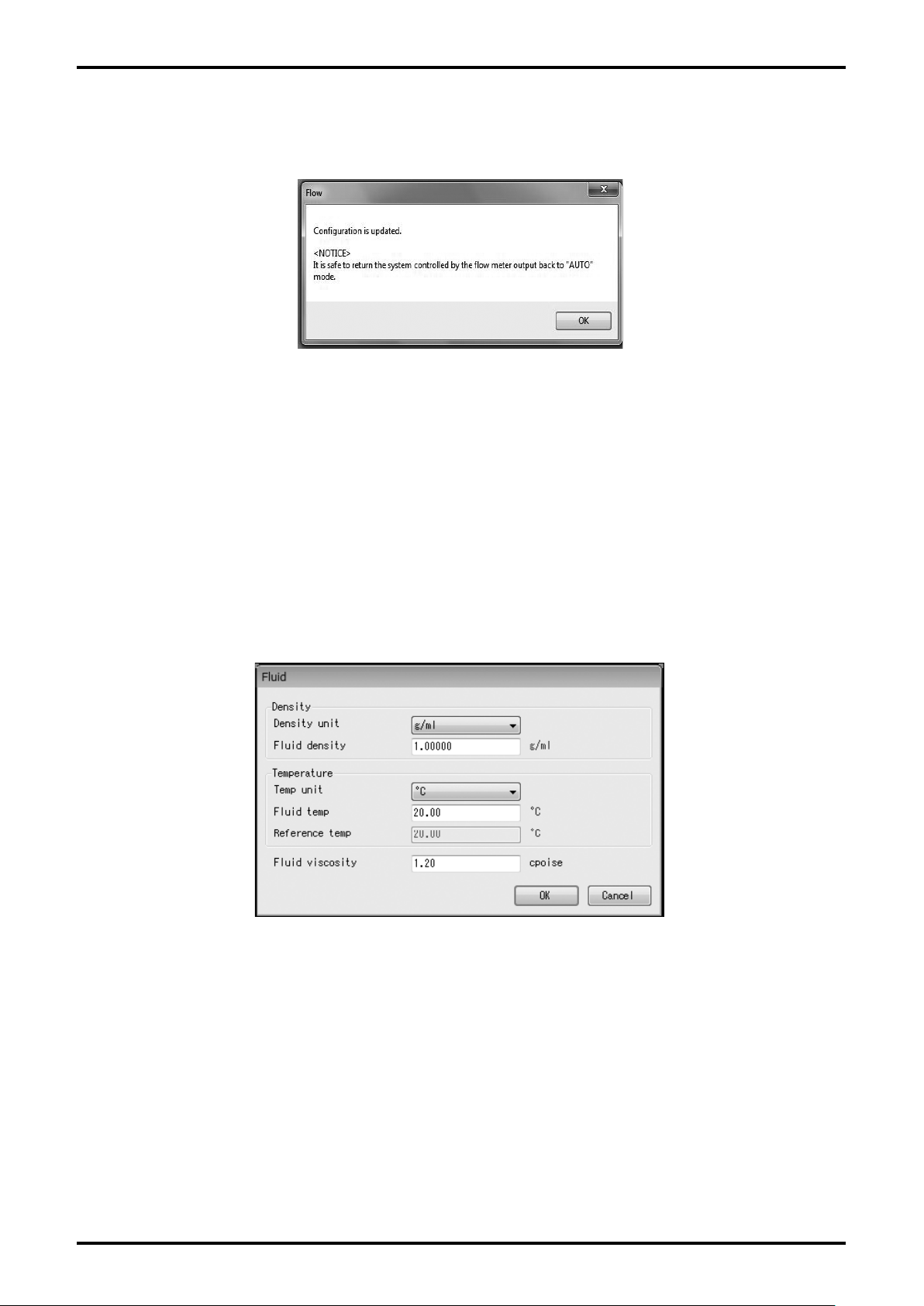
(4) If all settings are completed, click "OK" button. Then, the message box (Fig. 3-31) will be displayed.
Click "OK" button here to change the settings to the inputted values, and to reflect the changed
setting values in the flowmeter's output. If the flowmeter's output is used to control valves or other
such parts as safety protocol, change the control loop to manual control so that the control loop
cannot be influenced by the flowmeter's output.
Fig. 3-31
23
Page 24
E-026-3-E
24
Click "OK" button. If the value is changed to the selected setting value, the message box (Fig. 3-32)
will be displayed. Click "OK" button to complete the setting.
Fig. 3-32
(6) After clicking "OK" button, the window will return to the window for inputting the item. Click "Cancel"
button to close the window for inputting the item.
o cancel the setting, click "Cancel" button during the steps (2) to (4).
T
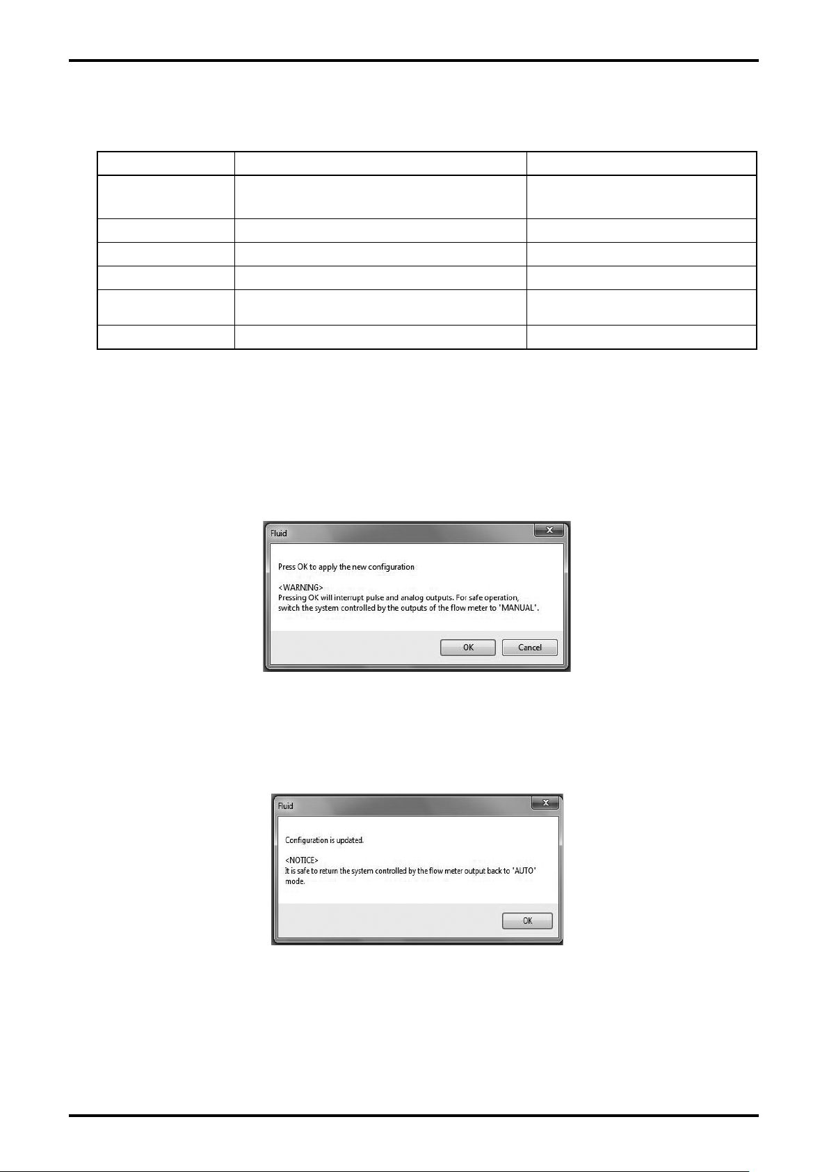
3.6.2.2 Fluid (parameter setting related to fluid)
(1) Click "Setup (S)" from the menu, and then click on "Fluid" from the drop-down list of "Fld dev vars".
(2) The following window (Fig. 3-33) will be displayed. Here, set the parameter related to fluid.
Fig. 3-33
Page 25
E-026-3-E
(3) Select and input a value for respective items. To change the unit, it is also necessary to change the
values of fluid density and fluid temperature.
Setting item Detail Setting range
Density unit Fluid density unit
Fluid density Fluid density 0.1 to 90 (in case of g/ml)
Temp unit Temperature unit °C, °F
Fluid temp Fluid temperature -20.00 to 120.00 (in case of °C)
Reference temp
Fluid viscosity Fluid viscosity 0.01 to 999.99 (cpoise)
Reference temperature for temperature
compensation
kg/CuMtr, lb/gal, lb/CuFt, g/ml,
lb/CuIn
Only for reference
(4) Once all settings are completed, click "OK" button. Then, the message box (Fig. 3-34) will be
displayed.
lick "OK" here to change the settings to the inputted values, and to reflect the changed setting
C
values in the flowmeter's output. If the flowmeter's output is used to control valves or other such
parts as safety protocol, change the control loop to manual control so that the control loop cannot be
influenced by the flowmeter's output.
Fig. 3-34
(5) Click "OK" button. If the setting is changed to the setting value you input, the message box (Fig. 3-35)
will be displayed. Click "OK" button to complete the setting.
Fig. 3-35
After clicking "OK" button, the window will return to the window for inputting the item. Click "Cancel"
(6)
button to close the window for inputting the item.
o cancel the setting, click "Cancel" button during the steps (2) to (4).
T
25
Page 26
E-026-3-E
26
3.6.3 Outputs (output setting)
3.6.3.1 Pulse output (pulse output setting)
(1) Click "Setup (S)" from the menu, and then click on "Pulse output" from the drop-down list of
"Outputs".
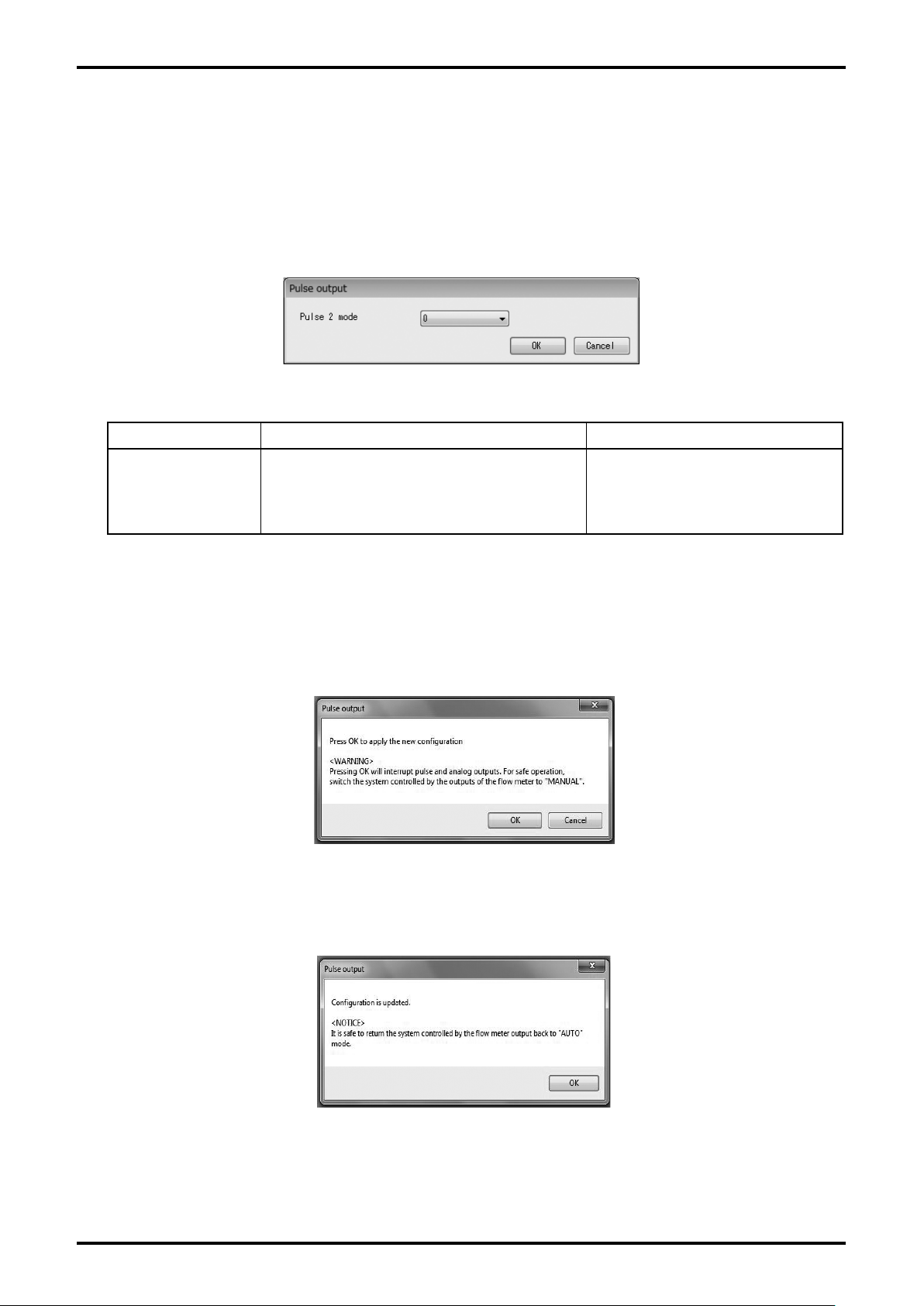
The following window (Fig. 3-36) will be displayed. Here, set the mode of pulse output.
(2)
Fig. 3-36
Setting item Detail Setting range
Pulse 2 output assignment
Pulse 2 mode
0: inversion of pulse 1
1:
reverse direction (in case of both of
forward and reverse directions)
0, 1
(3) Click "OK" after the setting is completed. Then the message box (Fig. 3-37) will be displayed.
Click "OK" here to change the settings to the inputted values, and to reflect the changed setting
values in the flowmeter's output. If the flowmeter's output is used to control valves or other such
parts as safety protocol, change the control loop to manual control so that the control loop cannot be
influenced by the flowmeter's output.
Fig. 3-37
(4) Click "OK" button. If the setting is changed to the selected setting value, the message box (Fig. 3-38)
will be displayed. Click "OK" button to complete the setting.
Fig. 3-38
(5) After clicking "OK" button, the window will return to the window for inputting the item. Click "Cancel"
button to close the window for inputting the item.
o cancel the setting, click "Cancel" button during (2) to (3).
T
Page 27
E-026-3-E
3.6.3.2 Status output (status output setting)
(1) Click "Setup (S)" from the menu, and then click on "Status output" from the drop-down list of
"Outputs".
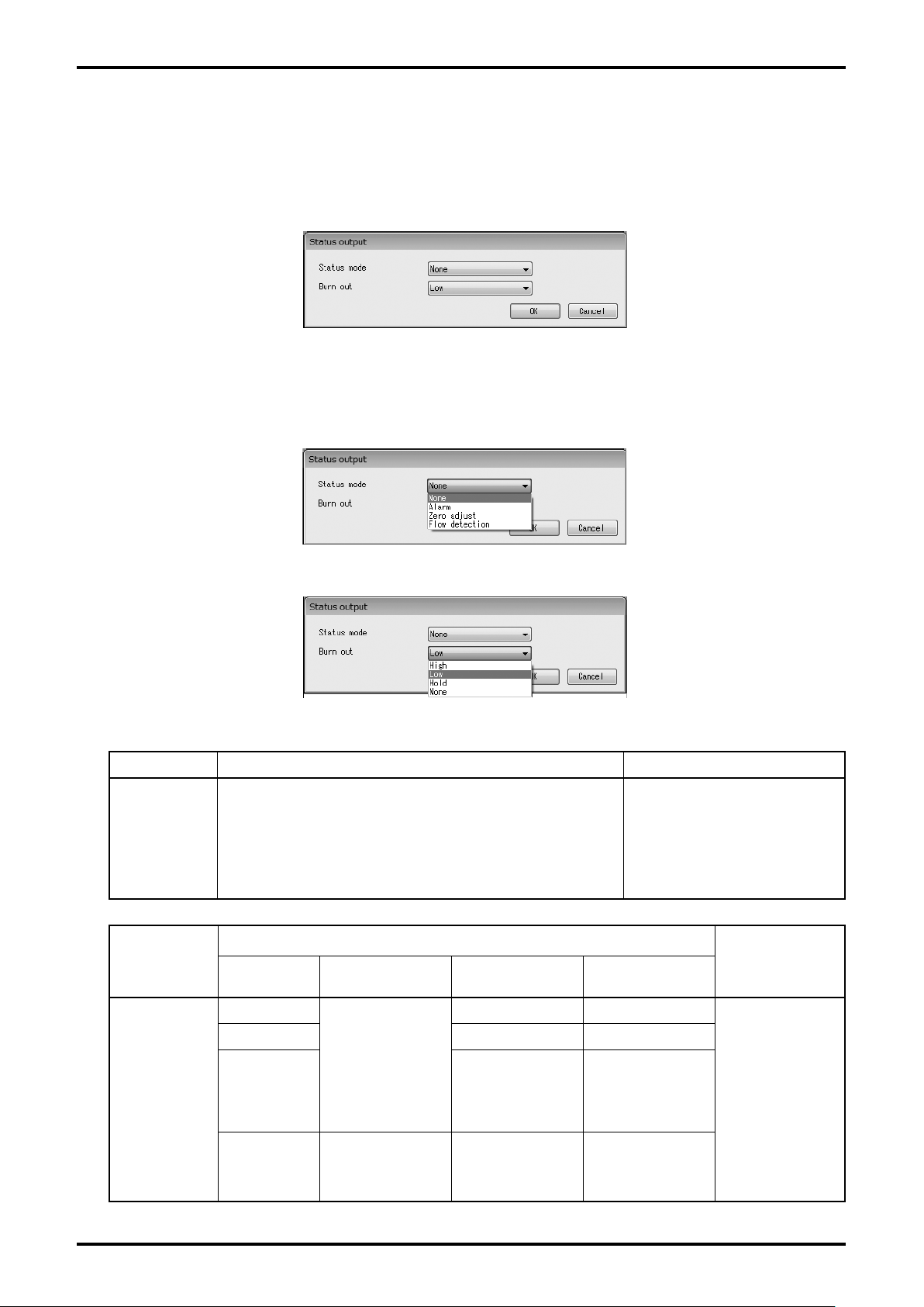
The following window (Fig. 3-39) will be displayed. Here, set the function of status output.
(2)
Fig. 3-39
(3) Click the arrow on the right side of "Status mode" and "Burn out" as shown in Fig. 3-40, Fig. 3-41,
and then select an item to be set from the drop-down list.
Fig. 3-40
Fig. 3-41
Setting item Detail Setting range
Status output mode
None: no function, contact output OFF
Status mode
Setting item
Alarm: ACTIVE when alarm is generated
Zero adjust: ACTIVE during zero point adjustment
Flow detection: ACTIVE at the occurrence of reverse
flow
Detail
Alarm output
setting
High
LCD Analog Pulse 1 / 2
21.6mA 0Hz (stop)
None, Alarm,
Zero adjust, Flow detection
Setting range
Burn out
Low 3.6mA 0Hz (stop)
Hold
None
Hold
Measured flow
rate is displayed
regardless of
error
Value immediately
before generation
of an error is
continued up to
recovery
Measured flow
rate is output
regardless of
error
Value immediately
before generation
of an error is
continued up to
recovery
Measured flow
rate is output
regardless of
error
High, Low,
Hold, None
27
Page 28
E-026-3-E
28
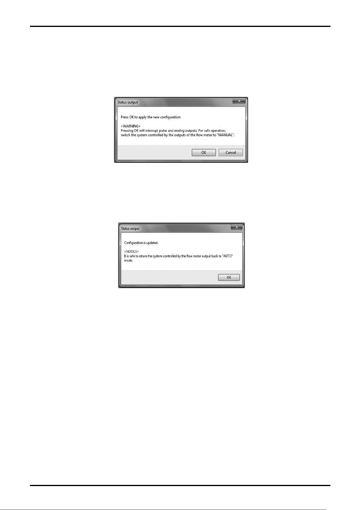
(4) Click "OK" button after all settings are completed. Then the message box (Fig. 3-42) will be displayed.
Click "OK" here to change the settings to the inputted values, and to reflect the changed setting
values in the flowmeter's output. If the flowmeter's output is used to control valves or other such
parts as safety protocol, change the control loop to manual control so that the control loop cannot be
influenced by the flowmeter's output.
Fig. 3-42
(5) Click "OK" button. If the value is changed to the selected setting value, the message box (Fig. 3-43)
will be displayed. Click "OK" button to complete the setting.
Fig. 3-43
(6) After clicking "OK" button, the window will return to the window for inputting the item. Click "Cancel"
button to close the window for inputting the item.
o cancel the setting, click "Cancel" button during the steps (2) to (4).
T
Page 29
3.6.4 Device information (transmitter information setting)
(1) Click "Setup (S)" from the menu, and then click on "Device information".
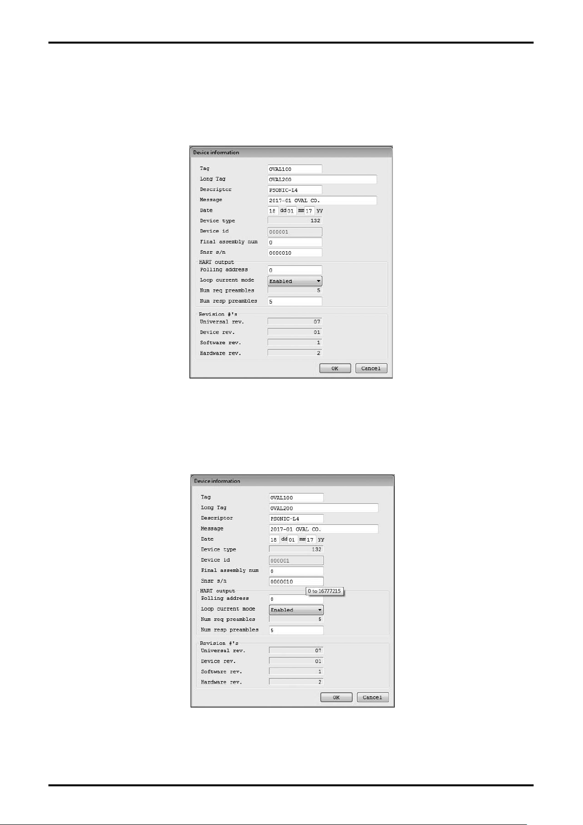
(2) The following window (Fig. 3-44) will be displayed. Here, set the transmitter information.
E-026-3-E
Fig. 3-44
(3) Set each item. If you point the cursor to the input field, the guide for input restriction shown in Fig.
3-45 will appear. Reference it at the setting.
Fig. 3-45
29
Page 30
E-026-3-E
30
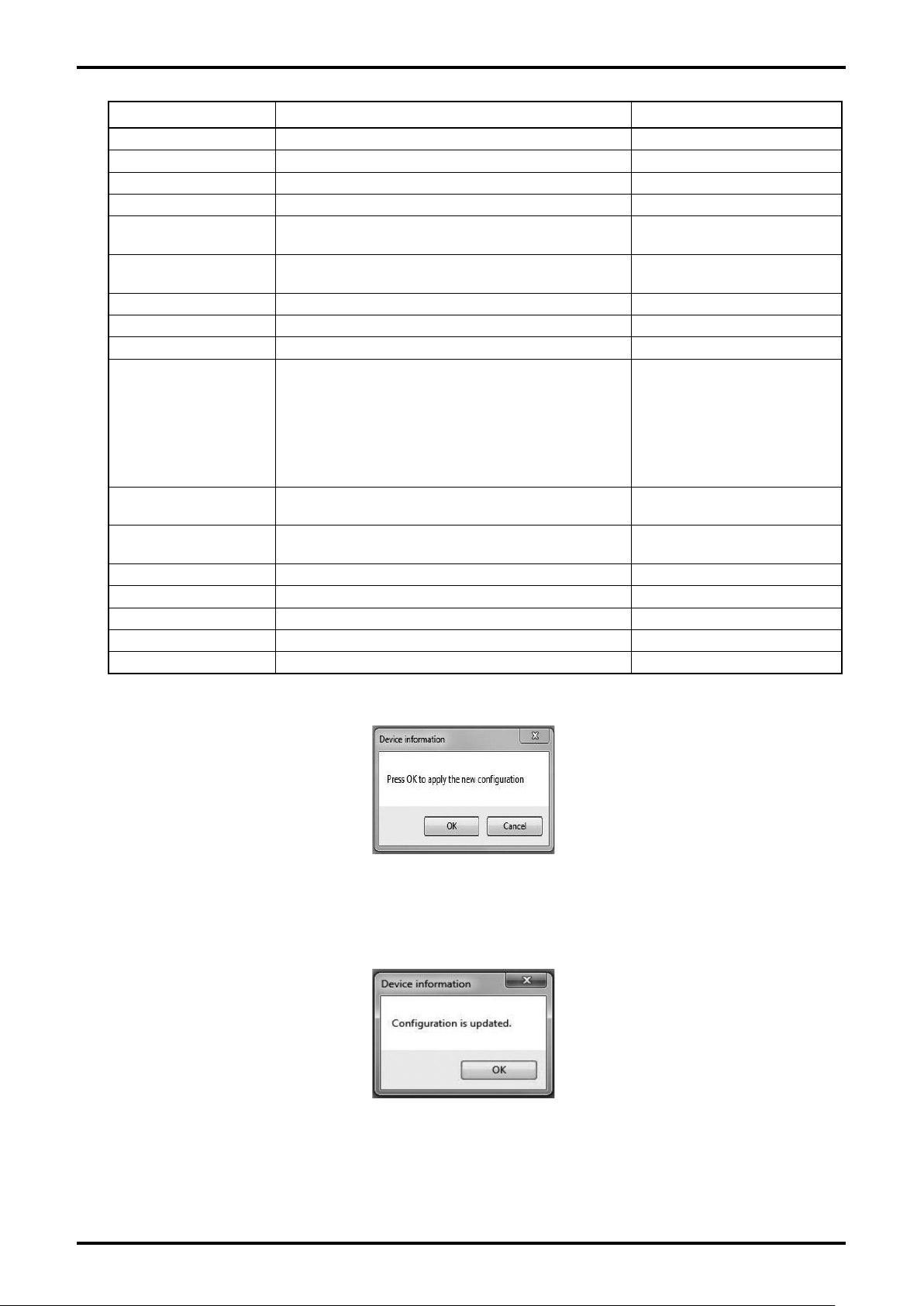
Setting item Detail Setting range
Tag Tag number 8 alphanumeric characters
Long Tag Tag number 32 alphanumeric characters
Descriptor Description 16 alphanumeric characters
Message Message 32 alphanumeric characters
Date Production date
Device type Device type of transmitter
Device id Device ID of transmitter Only for reference
Final assembly num Production number 0 to 16777215
Snsr s/n Sensor type 0 to 16777215
HART polling address for communication (address
for multi drop)
Polling address
Default value: 0
*
When connecting multiple flowmeters on the
same segment, set the address other than "0"
that is not duplicative for each flowmeter.
Positive integer of 2 digits of
day, month, and year
132 (registered device
number)
0 to 63
Loop current mode Loop current mode
Num req preambles
Num resp preambles HART communication receiving preamble number 5 to 20
Universal rev. Universal revision of HART communication Only for reference
Device rev. Field device revision Only for reference
Software rev. Software revision Only for reference
Hardware rev. Hardware revision Only for reference
HART communication transmission preamble
number
Disabled
Enabled
Only for reference
(4) Click "OK" button after all settings are completed to display the message box (Fig. 3-46).
Fig. 3-46
(5) Click "OK" button. If the setting is changed to the setting value you input, the message box (Fig. 3-47)
will be displayed. Click "OK" button to complete the setting.
Fig. 3-47
After clicking "OK" button, the window will return to the window for inputting the item. Click "Cancel"
(6)
button to close the window for inputting the item.
T
o cancel the setting, click "Cancel" button during the steps (2) to (4).
Page 31
E-026-3-E
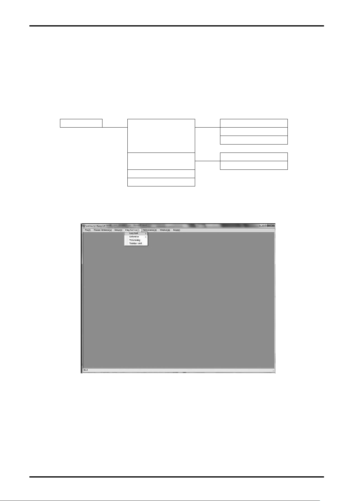
3.7 Menu: Diag / Service (check / adjustment)
"Diag/Service" can be used to diagnose the flowmeter transmitter, perform loop tests on each output,
adjust output values, calibrate the sensitivity of flow rate sensor, and reset cumulative totals.
Close all "Setup (S)" windows to enable checking and adjustment functions.
Also note that other than "Loop test", the "Diag/Service (T)" window cannot be displayed simultaneously
with multiple windows (other than "Totalizer control").
The actual screen is as shown in Fig. 3-48.
Diag/Service
Loop test
Calibration
Trim Analog
Totalizer cntrl
Diag/Service Item Tree
Fix Analog
Fix Pulse
Fix Flow
Auto zero
Init AGC
Fig. 3-48
31
Page 32
E-026-3-E
32
3.7.1 Loop Test (loop test)
Simulated output will be created.
3.7.1.1 Fix Analog (analog output loop test)
This test can be used to put analog output into a simulated output state, and to verify the output line with
a loop test.
The test creates simulated output regardless of the process state. If the flowmeter's output is used to
control valves or other such parts, change the control loop to manual control for the sake of safety, and
so that the control loop cannot be influenced by the flowmeter's output.
NOTE: If the loop current mode is set to "Disabled", this test is unusable.
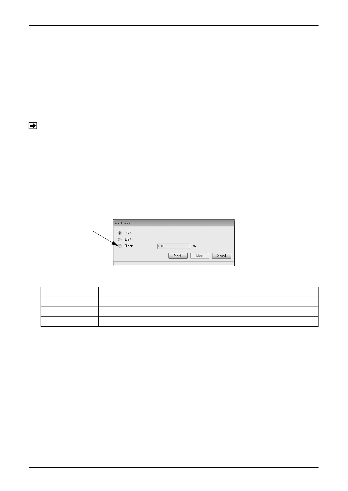
(1) Click "Diag/Service (T)" from the menu, and then click on "Fix Analog" from the drop-down list of
"Loop Test".
The following window (Fig. 3-49) will be displayed. Select the simulated output value and click "Start"
(2)
button. To set and output a desired current value, select "Other" and enter the value to be output,
then click "Start" button.
By clicking "Cancel" button, "Fix Analog" will be exit
ed.
To create a desired analog
simulated output,
click here and enter
the value.
Fig. 3-49
Setting item Detail Setting range
4mA 4mA fixed output -
20mA 20mA fixed output -
Other Sets a desired output value 2.4 to 21.6mA
Page 33
E-026-3-E
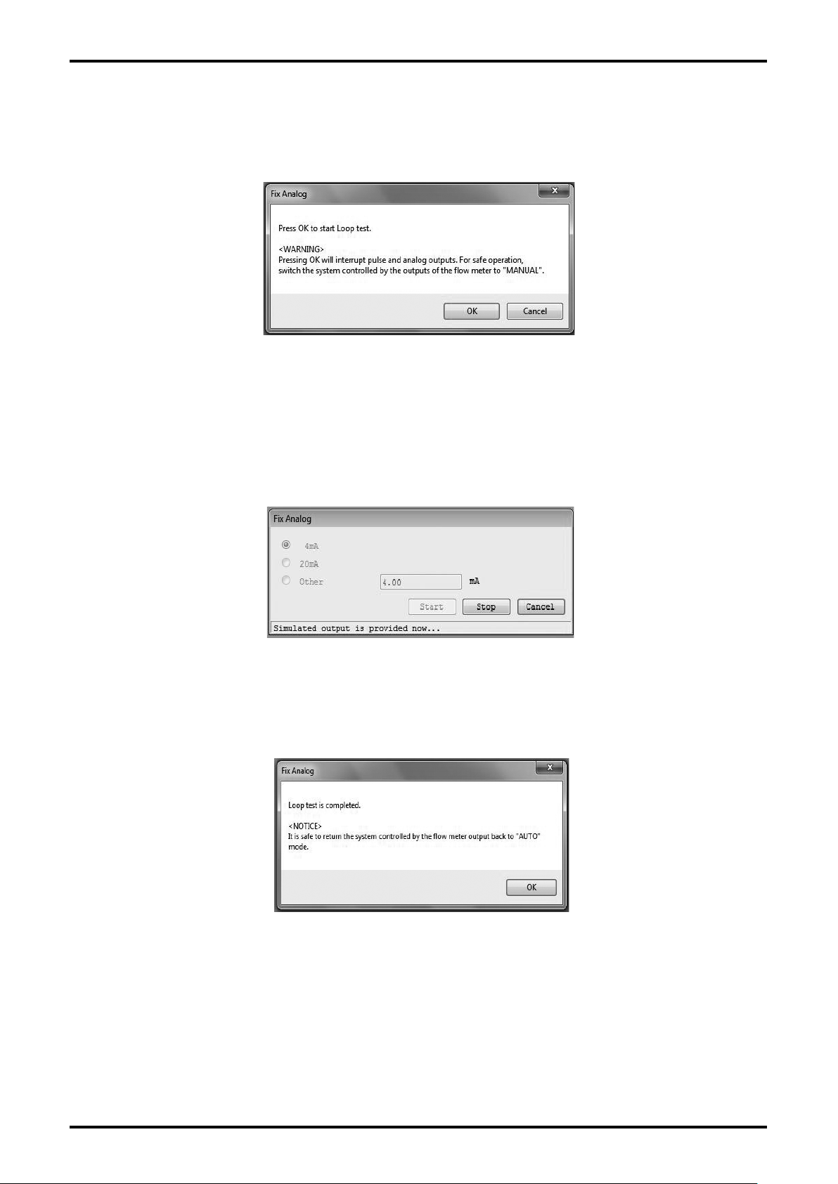
(3) By clicking "Start" button, the message box (Fig. 3-50) will be displayed. By clicking "OK" button,
"Fix Analog" will be started. By clicking "Cancel" button, the window will return to the window shown
in Fig. 3-49.
Fig. 3-50
(4) By clicking "OK" button, the analog value you set will be output. While the simulated output value is
output, a message "Simulated output is provided now." is displayed at the bottom of the window as
shown in Fig. 3-51.
Click "Stop" button to stop the simulated output.
Fig. 3-51
(5) By clicking "Stop" button, the message box (Fig. 3-52) will be displayed. Click "OK" button.
Fig. 3-52
(6) By clicking "OK" button, the window will return to the window shown in Fig. 3-51. Click "Cancel"
button to exit "Fix Analog".
33
Page 34
E-026-3-E
34
3.7.1.2 Fix Pulse (pulse output loop test)
This test can be used to put pulse output into a simulated output state, and to verify the output line with a
loop test.
The test creates simulated output regardless of the process state. If the flowmeter's output is used to
control valves or other such parts, change the control loop to manual control for the sake of safety, and
so that the control loop cannot be influenced by the flowmeter's output.
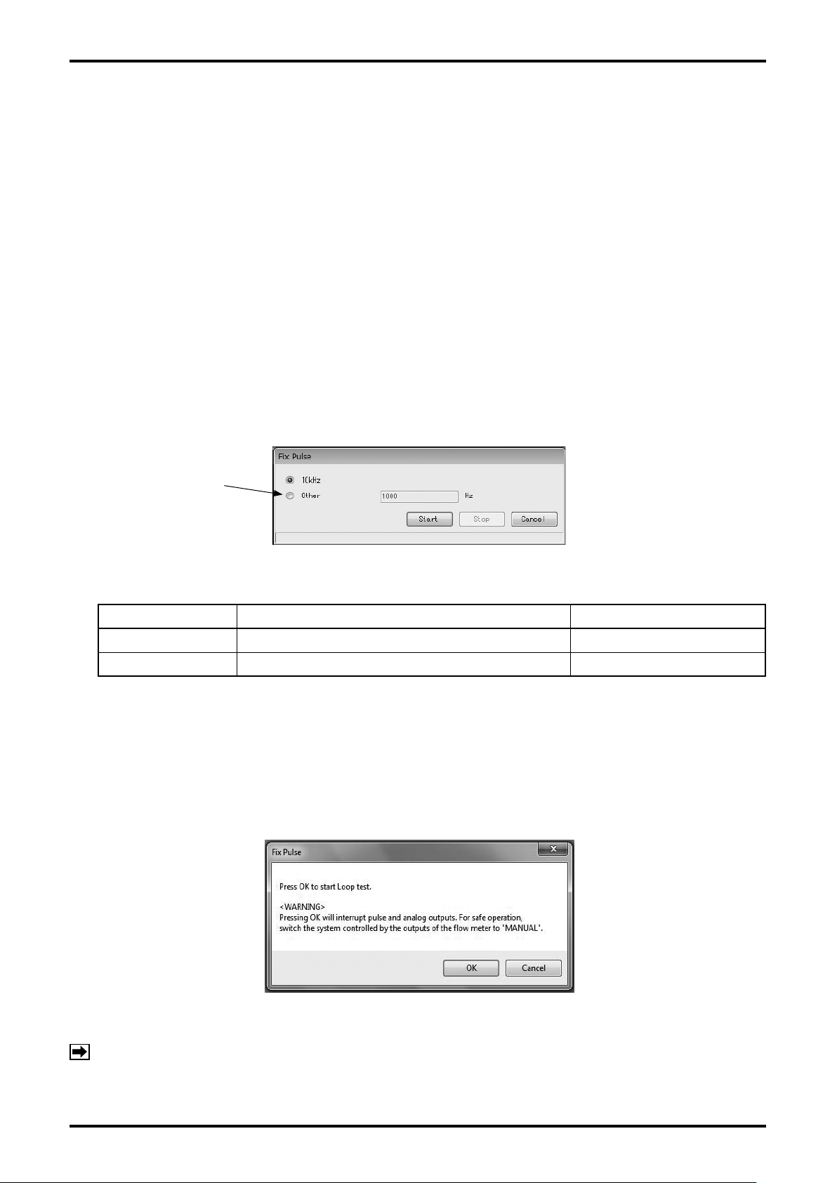
Click "Diag/Service (T)" from the menu, and then click on "Fix Pulse" from the drop-down list of "Loop
(1)
Test".
The following window (Fig. 3-53) will be displayed. Select the simulated output value and click "Start"
(2)
button. To set and output a desired output value, select "Other" and enter the pulse frequency to be
output, then click "Start" button.
The
available range of pulse frequency is 1 to 11000Hz. By clicking "Cancel" button, "Fix Pulse" is
exited.
To create a desired analog
simulated output,
click here and enter
the value.
Fig. 3-53
Setting item Detail Setting range
10kHz 10kHz fixed output -
Other Sets a desired output value 1 to 11000Hz
(3) By clicking "Start" button, the message box (Fig. 3-54) will be displayed. By clicking "OK" button,
"Fix Pulse" will be started.
By clicking "Cancel" button, the window will r
eturn to the window shown in Fig. 3-53.
Fig. 3-54
NOTE: Note that the cumulative total of flowmeter is also counted when the simulated output is
created.
Page 35
E-026-3-E
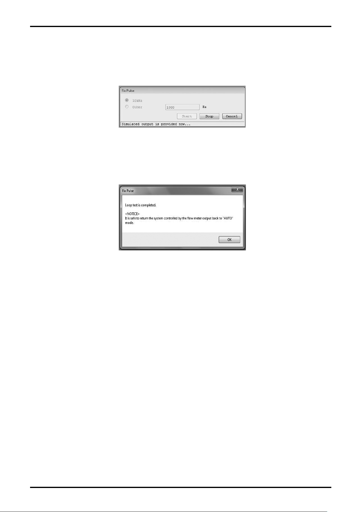
(4) By clicking "OK" button, the simulated output value you set will be output. While the simulated output
value is output, a message "Simulated output is provided now." is displayed at the bottom of the
window as shown in Fig. 3-55.
Click "Stop" button to stop the simulated output.
Fig. 3-55
(5) By clicking "Stop" button, the message box (Fig. 3-56) will be displayed. Click "OK" button.
Fig. 3-56
(6) By clicking "OK" button, the window will return to the window shown in Fig. 3-53. Click "Cancel"
button to exit "Fix Pulse".
3.7.1.3 Fix Flow (simulated flow rate loop test)
This puts status output into a simulated output state, and conducts a loop test on the output line.
Analog output and pulse output will be created according to the simulated flow rate you set.
This test creates simulated output regardless of the process state. If the flowmeter's output is used to
control valves or other such parts, change the control loop to manual control for the sake of safety, and
so that the control loop cannot be influenced by the flowmeter's output.
Click "Diag/Service (T)" from the menu, and then click on "Fix Flow" from the drop-down list of "Loop
(1)
Test".
35
Page 36
E-026-3-E
36
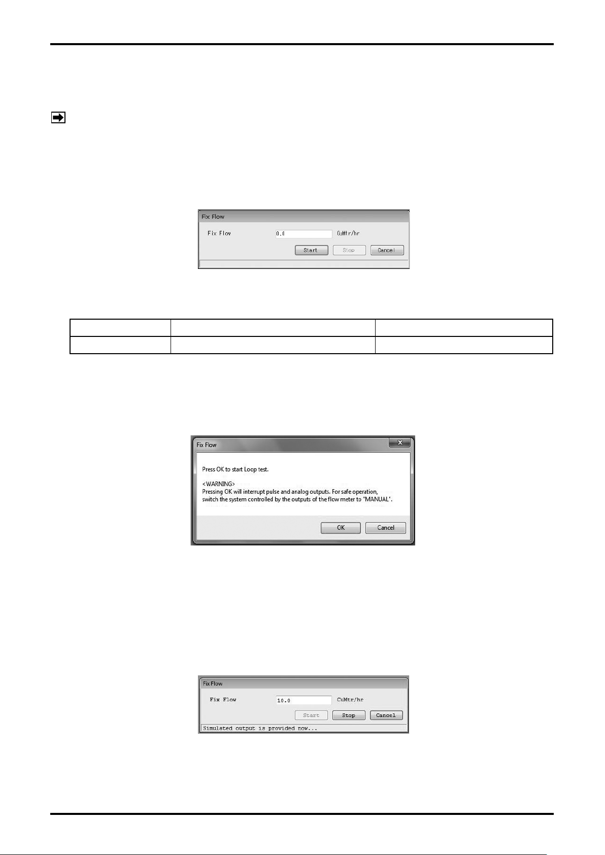
(2) The following window (Fig. 3-57) will be displayed. Set a simulated flow rate value and click "Start"
button. By clicking "Cancel" button, "Fix Flow" will be exited.
NOTE: Note that difference may be generated between input flow rate and LCD display of flowmeter
body, and output value and set flow rate in this simulated output mode depending on the
parameter setting.
M
oreover, note that the cumulative total of flowmeter is also counted when the simulated
output is created.
Fig. 3-57
Setting item Detail Setting range
Fix Flow Fixed output of instantaneous flow rate -9999.0 to 9999.0 (setting unit)
(3) By clicking "Start" button, the message box (Fig. 3-58) will be displayed. By clicking "OK" button,
"Fix Flow" will be started.
By clicking "Cancel" button, the window will r
(4) By clicking "OK" button, the simulated flow rate value you set will be output. While the simulated flow
rate value is output, a message "Simulated output is provided now." is displayed at the bottom of the
window as shown in Fig. 3-59.
Click "Stop" button to stop the simulated output.
eturn to the window shown in Fig. 3-57.
Fig. 3-58
Fig. 3-59
Page 37
E-026-3-E
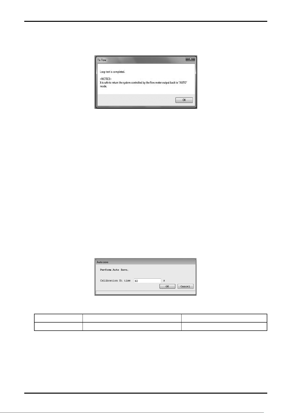
(5) By clicking "Stop" button, the message box (Fig. 3-60) will be displayed. Click "OK" button.
Fig. 3-60
(6) By clicking "OK" button, the window will return to the window shown in Fig. 3-57. Click "Cancel"
button to exit "Fix Flow".
3.7.2 Calibration (transmitter's adjustment function)
This executes the adjustment function of flowmeter transmitter.
3.7.2.1 Auto zero (auto zero point adjustment)
This adjusts the zero point for flow rate measurement of flowmeter transmitter.
(1) Click "Diag/Service (T)" from the menu, and then click on "Auto zero" from the drop-down list of
"Calibration".
The following window (Fig. 3-61) will be displayed. Set the calibration time and stop the fluid
(2)
completely, and then click "OK" button.
Fig. 3-61
Setting item Detail Setting range
Calibration Dt time Zero point adjustment execution time 60 to 600 (seconds)
37
Page 38
E-026-3-E
38
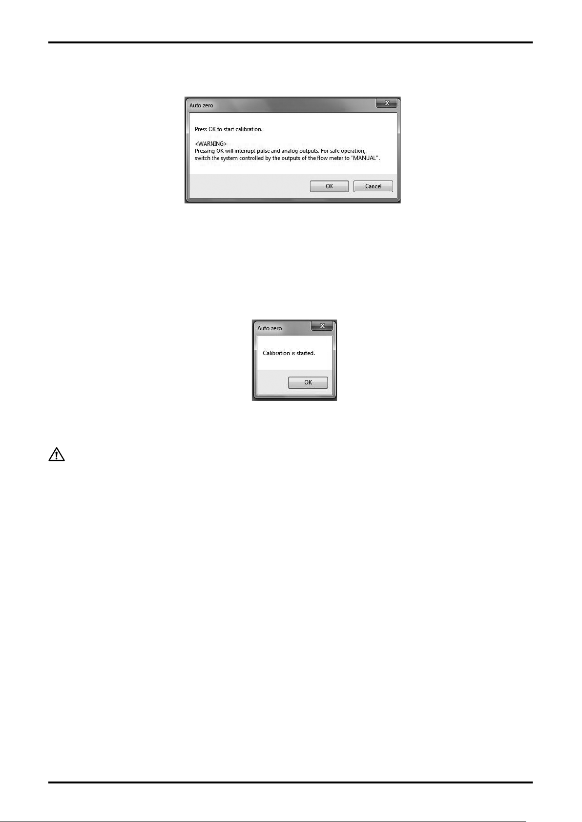
(3) Click "OK" button. By clicking it, the message box (Fig. 3-62) will be displayed.
Fig. 3-62
(4) By clicking "OK" button, the zero point adjustment will be executed. When it is started, the message
box (Fig. 3-63) will be displayed. By clicking "OK" button, the window will return to the window shown
in Fig. 3-61. Click "Cancel" button to exit it. During this time, the transmitter executes the zero point
adjustment.
Fig. 3-63
CAUTION: The process fluid in the measurement pipe of flowmeter has to be
completely stopped.
Otherwise, the zer
o point adjustment cannot be correctly executed.
Also, It may not be executed if an error exists in the flow rate measure-
ment.
Page 39
E-026-3-E
3.7.2.2 Init AGC (sensitivity adjustment)
This adjusts the sensitivity of flow rate sensor.
(1) Click "Diag/Service (T)" from the menu, and then click on "Ini t A GC" from the down- list of
"Calibration".
The following window (Fig. 3-64) will be displayed. Stop the fluid completely, and then click "OK"
(2)
button.
Fig. 3-64
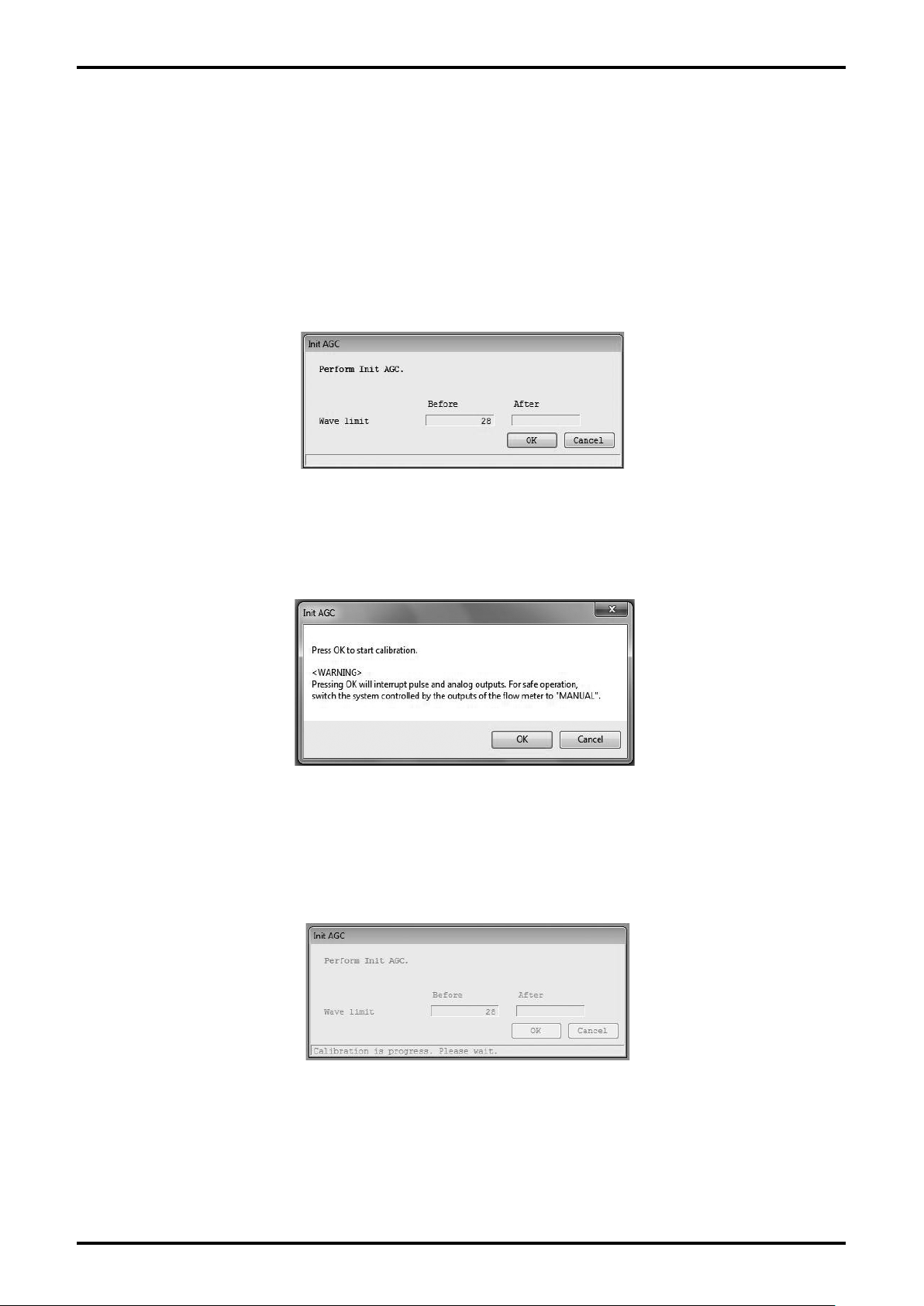
(3) Click "OK" button. By clicking it, the message box (Fig. 3-65) will be displayed.
Fig. 3-65
(4) By clicking "OK" button, the sensitivity adjustment will be executed. The screen during adjustment
displays the process during adjustment as shown in Fig. 3-66.
Fig. 3-66
39
Page 40
E-026-3-E
40
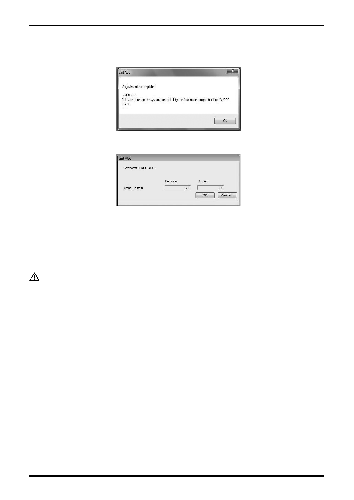
(5) Once the adjustment is completed, the message box (Fig. 3-67) will be displayed. Click "OK" button.
The value after the adjustment will be displayed as shown in Fig. 3-68.
Fig. 3-67
Fig. 3-68
(6) By clicking "OK" button, the window will return to the window shown in Fig. 3-64. Click "Cancel"
button to exit "Init AGC".
CAUTION: "Init AGC" may not be executed if an error exists in the flow rate
measurement.
Page 41
E-026-3-E
3.7.3 Trim Analog (analog output adjustment)
This adjusts the output value of the flowmeter transmitter's analog output.
This function is for adjusting the values by outputting analog values equivalent to 4mA and 20mA
regardless of the processing state. If the flowmeter's output is used to control valves or other such
parts as safety protocol, change the control loop to manual control so that the control loop cannot be
influenced by the flowmeter's output.
NOTE: If the loop current mode is set to "Disabled", this test is unusable.
(1) Click "Diag/Service (T)" from the menu, and then click on "Trim Analog".
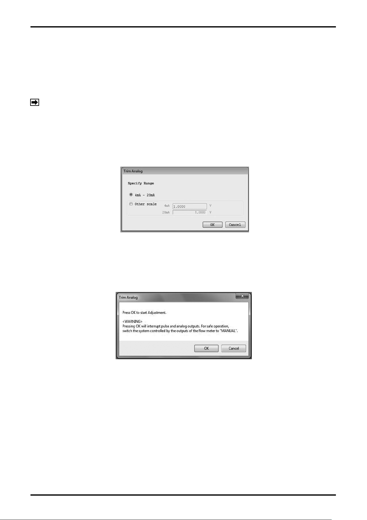
(2) The following window (Fig. 3-69) will be displayed. Select the scale from "4mA - 20mA" or "Other
scale" and click "OK".
Fig. 3-69
By clicking "OK" button, the message box (Fig. 3-70) will be displayed. To adjust the analog output,
(3)
click "OK" button.
Fig. 3-70
When "4mA - 20mA" is used for adjustment, insert a reference ammeter into the analog output loop,
and perform the adjustment following the method described in steps (4) to (7).
When
"Other scale" is used, insert a load resistance into the analog output loop, and perform the
adjustment following the method described in steps (8) to (12) (this description covers the situation
where R
= 250Ω is inserted to make an adjustment on both ends of the voltage value scale of 1 to
L
5V).
41
Page 42
E-026-3-E
42
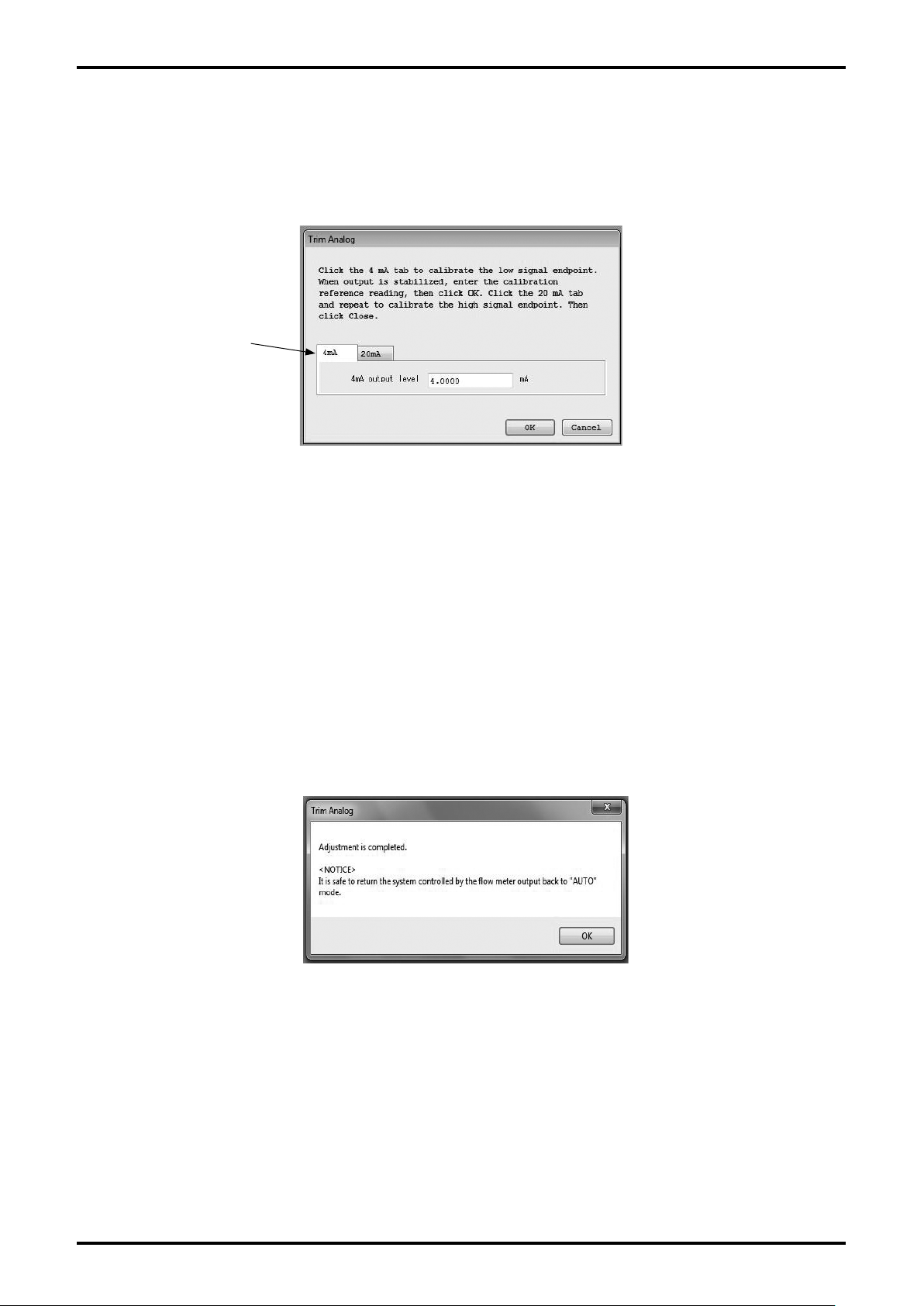
(4) If you select "4mA−20mA" on the window shown in Fig. 3-69 and click "OK" button, the window
shown in Fig. 3-71 will be displayed. Select whether 4mA or 20mA should be used for the adjustment.
Here, 4mA adjustment is executed and then 20mA adjustment is executed in order.
Enter the curr
Click here and select
which adjustment
should be executed.
ent reading of the ammeter output and click "OK" button.
Fig. 3-71
When the reading is sent, the transmitter automatically adjusts the output to 4mA. Verify that the
connected ammeter indicates 4mA.
f another adjustment is required, enter the reading of the ammeter again on this window and click "OK"
I
button.
(5)
To execute 20mA adjustment, click 20mA side on the window shown in Fig. 3-71 and execute
adjustment so that the connected ammeter indicator reads 20mA in the same manner as 4mA
adjustment.
By clicking "Cancel" button, the adjustment of analog output value will be completed. The message
(6)
box "Adjustment is completed" shown in Fig. 3-72 will be displayed. Click "OK" button.
Fig. 3-72
To stop the adjustment during the process, click "Cancel" button and follow the following message.
(7)
Page 43
E-026-3-E
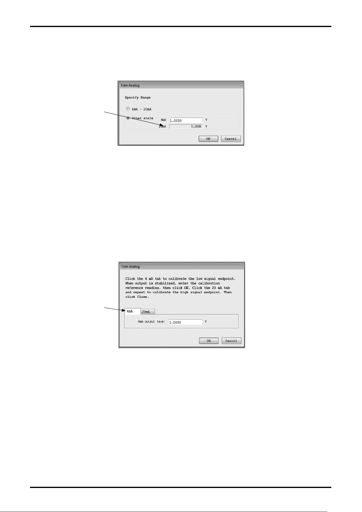
(8) When you select "Other scale" on the window shown in Fig. 3-69, the input of other scale will be
enabled as shown in Fig. 3-73. If you enter an analog value (here, 1V) equivalent to 4mA output in the
4mA entry field, the corresponding value will be automatically entered in the 20mA entry field.
It is not necessary to enter
a value in the lower field.
If you enter a value in the
upper field, the value will be
automatically entered in the
lower field.
Fig. 3-73
Here, analog output adjustment with 1 to 5V scale is available.
By clicking "OK" button, Fig. 3-70 will be displayed in the same manner. To execute the analog output
adjustment, click "OK" button. Additionally, click "OK" button to start the adjustment. Connect a
measuring instrument (reference voltmeter) across both ends of load resistance R
.
L
(9) The window shown in Fig. 3-74 will be displayed. Select whether 4mA adjustment or 20mA adjust-
ment should be executed.
Her
e, 4mA adjustment is executed and then 20mA adjustment is executed in order.
Enter the reading of a measuring instrument and click "OK" button.
Click here and select
which adjustment
should be executed.
Fig. 3-74
When the reading is sent, the transmitter automatically adjusts the output to 4mA. Verify that the
indicator of the connected measuring instrument is 1V.
If
another adjustment is required, enter the reading of a measuring instrument on this window and
click "OK" button.
(10)
To execute 20mA adjustment, click 20mA on the window shown in Fig. 3-74 and execute adjustment
so that the connected measuring instrument indicates 5V as in the same way as 4mA adjustment.
By clicking "Cancel" button, the adjustment of analog output value will be completed. The window
(11)
"Adjustment is completed" shown in Fig. 3-72 will be displayed. Click "OK" button.
To stop the adjustment during the process, click "Cancel" button and follow the following message.
(12)
43
Page 44
E-026-3-E
44
3.7.4 Totalizer cntrl (cumulative total control)
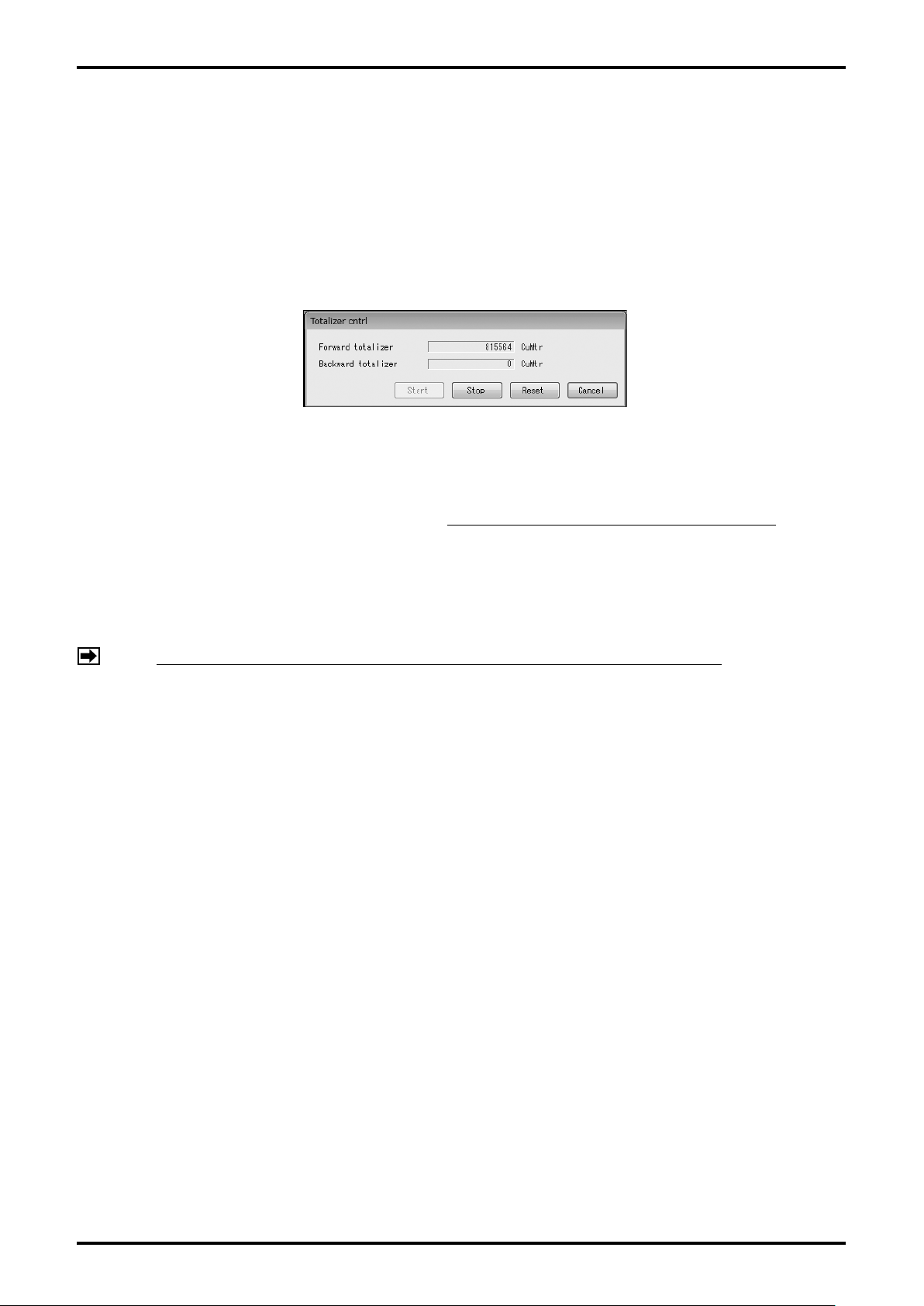
Use this for functions such as displaying the cumulative totals, and starting, stopping, and resetting the
count.
Click "Diag/Service (T)" from the menu, and then click on "Totalizer cntrl".
(1)
(2) The following window (Fig. 3-75) will be displayed.
Fig. 3-75
(3) On this window, "Start", "Stop", and "Reset" of cumulative total can be executed. As "Start", "Stop",
and "Reset" are interlocked with pulse output, note that pulse is not output in "Stop" status.
In usual status, "Start" or "Stop" is selected. The selected item is displayed in gray
If you execute "Reset", both of "Forward totalizer" and "Backward totalizer" will be reset to "0".
.
(4) To close the window of cumulative total control, click "Cancel" button.
NOTE: Usually, verify "Start" is displayed in gray (selected), and then close the menu.
Page 45
3.8 Menu: Maintenance (maintenance)
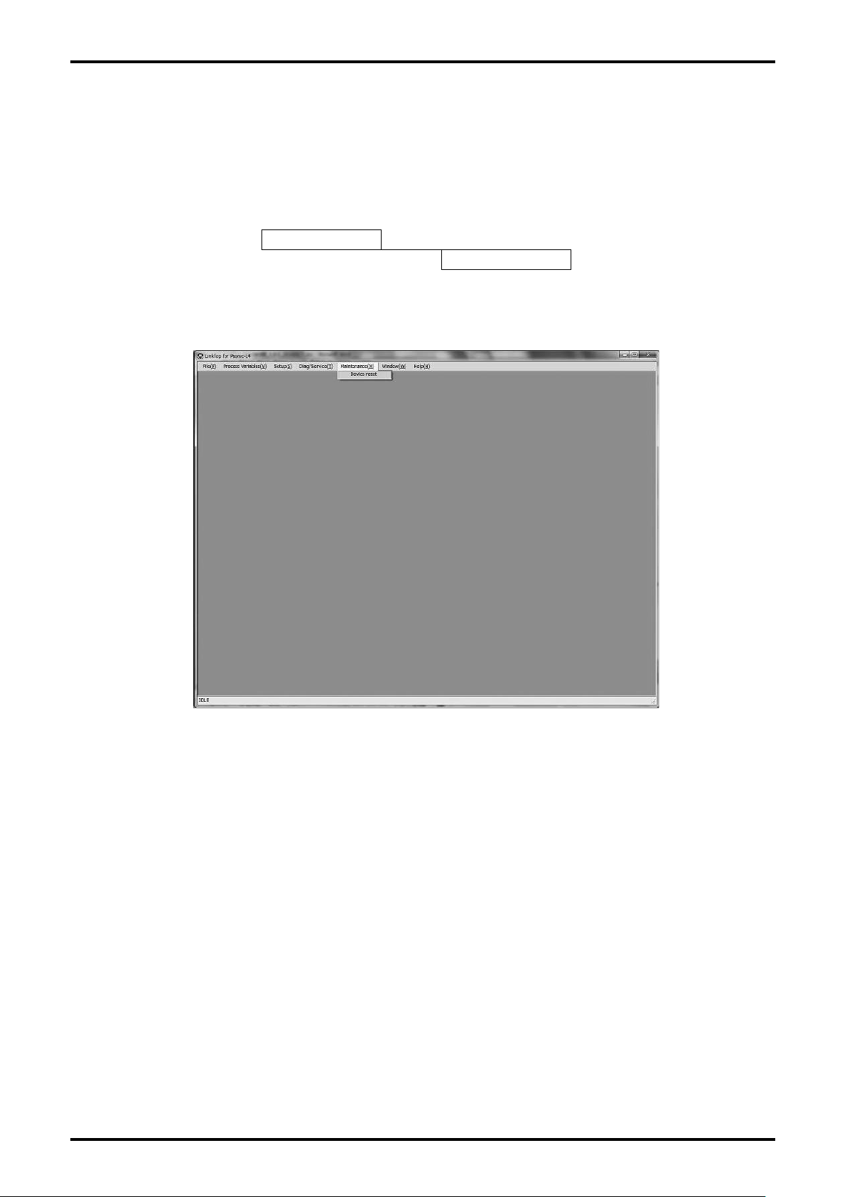
"Maintenance (M)" is used for resetting (rebooting) the transmitter.
The actual screen is as shown in Fig. 3-76.
Maintenance
Device reset
Maintenance Item Tree
E-026-3-E
Fig. 3-76
45
Page 46
E-026-3-E
46
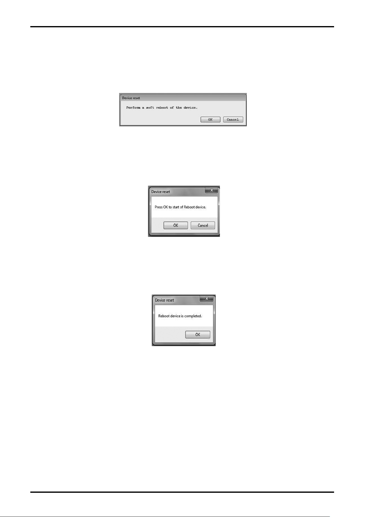
3.8.1 Device reset (transmitter reset)
(1) Click "Maintenance (M)" from the menu, and then click on "Device reset".
(2) The following window (Fig. 3-77) will be displayed.
Fig. 3-77
(3) By clicking "OK" button, the message box (Fig. 3-78) will be displayed. Here, if you click "OK" button,
the transmitter will be reset.
Fig. 3-78
(4) By clicking "OK" button, the message box (Fig. 3-79) will be displayed. By clicking "OK" button, the
reset of transmitter will be completed.
Fig. 3-79
(5) After clicking "OK" button, the window will return to the window for inputting the item. Click "Cancel"
button to close the window for inputting the item.
o stop the reset, click "Cancel" button during (2) to (3).
T
Page 47
3.9 Menu: Window (window)
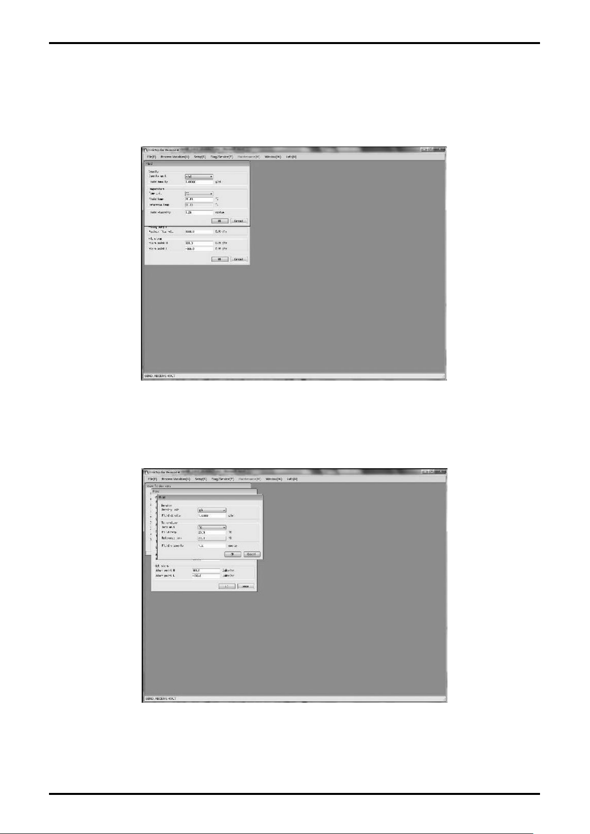
The "Window" menu can be used to arrange the currently displayed windows.
For the types to be arranged, "Cascade", "TileHorizontal", and "TileVertical" are available.
For instance, assume that multiple windows are being displayed, as shown in Fig. 3-80.
E-026-3-E
Fig. 3-80
(1) If "Cascade" is selected, the windows are overlaid as shown in Fig. 3-81.
Fig. 3-81
47
Page 48
E-026-3-E
48
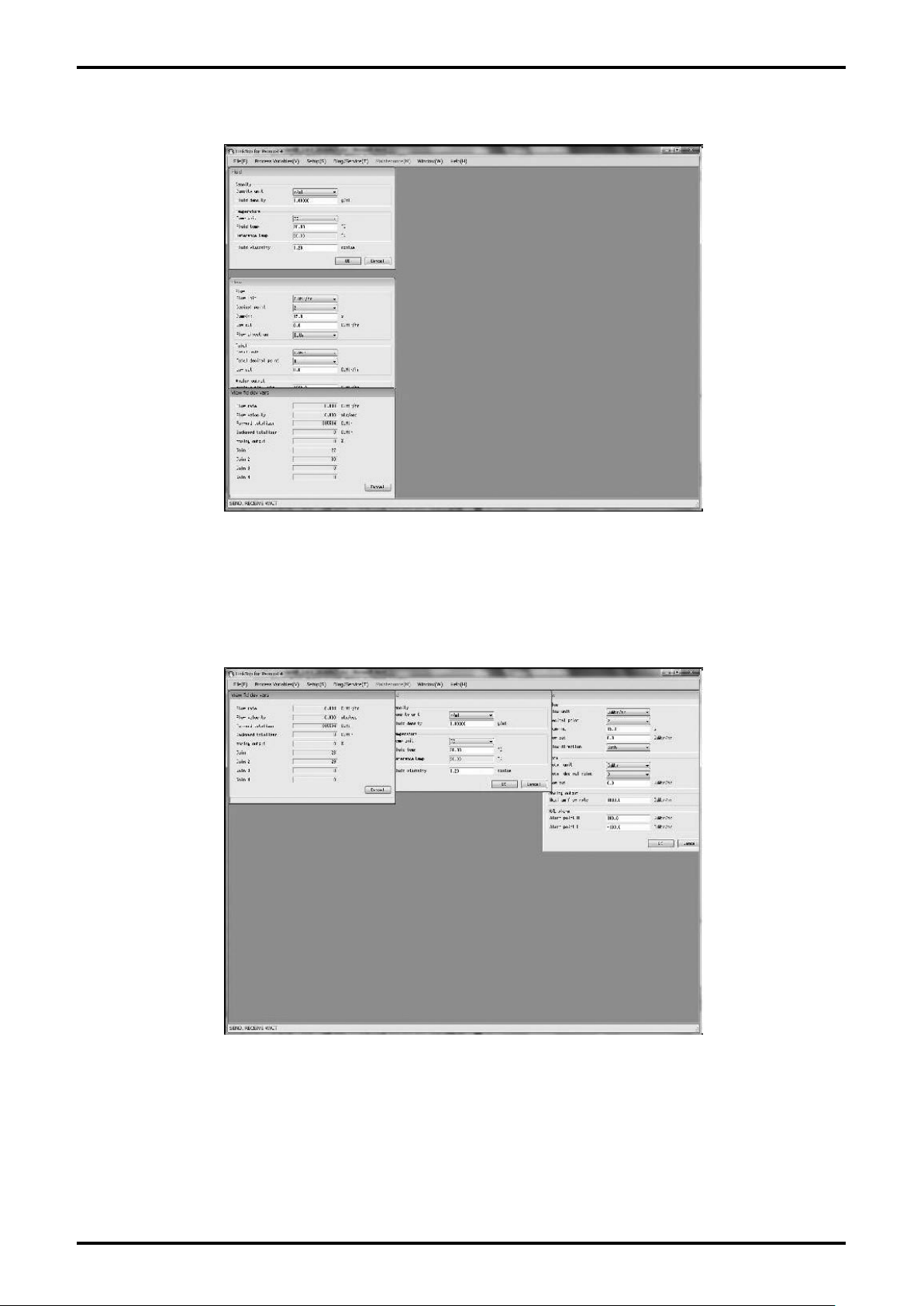
(2) If "TileHorizontal" is selected, the windows are displayed vertically as shown in Fig. 3-82.
Fig. 3-82
(3) If "TileVertical" is selected, the windows are displayed horizontally as shown in Fig. 3-83.
Fig. 3-83
Page 49
E-026-3-E
3.10 Menu: File (file)
The "File" menu can be used to connect communications (refer to section "3.2 Starting LinkTop and
Connections"), to termination of connection (refer to section "3.3 Terminating the Connection", and "3.4
Terminating LinkTop"), as well as to set ports (refer to section "3.2.2 Port setting"), to create a flowmeter
transmitter parameter database, and print parameters. This section describes the database and printing
features.
3.10.1 Database
The various parameters, transmitter information, etc., that are inputted through the "Setup" menu (described
in section 3.6) are stored in a database. This can be saved on a hard disk, flash memory, or other types of
storage medium. Setting values can also be downloaded to the flowmeter transmitter.
However, the data can be downloaded only when the write protect is set to "Not write protect".
3.10.1.1 Opening Files
It is possible to load data from a saved file.
(1) Click "File (F)" from the menu, and then click on "Open File (O)" from the drop-down list of "Database
(F)".
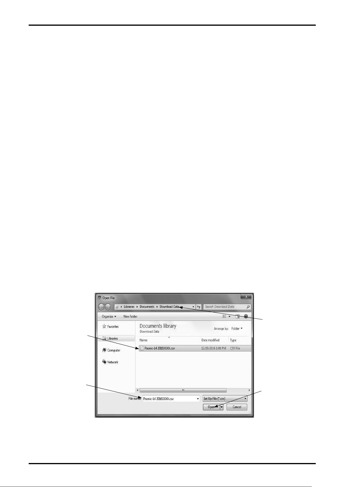
The common dialog box (Fig. 3-84) will be displayed. Select the drive and folder where the file to be
(2)
opened is stored from the drop-down list.
Select the file you want to open from the displayed files. Verify "File name (N)" and click "Open (O)"
(3)
button. Click "Cancel" button to exit the operation without opening the file.
Click here and select
drive and folder.
Click the icon of the
file to be opened.
The file name will be
displayed.
By clicking here, the
selected file will be
opened.
Fig. 3-84
49
Page 50
E-026-3-E
50
(4) Select a file you want to open from the displayed files. Verify "File name (N)" and click "Open (O)"
button. Click "Cancel" button to exit the operation without opening the file.
The parameters of the selected file can be printed. For printing, refer to "3.10.2 Printing".
(5)
3.10.1.2 Saving Files
It is possible to save parameters in the flowmeter transmitter to a file.
(1) Click "File (F)" from the menu, and then click on "Save File (S)" from the drop-down list of "Database
(F)".
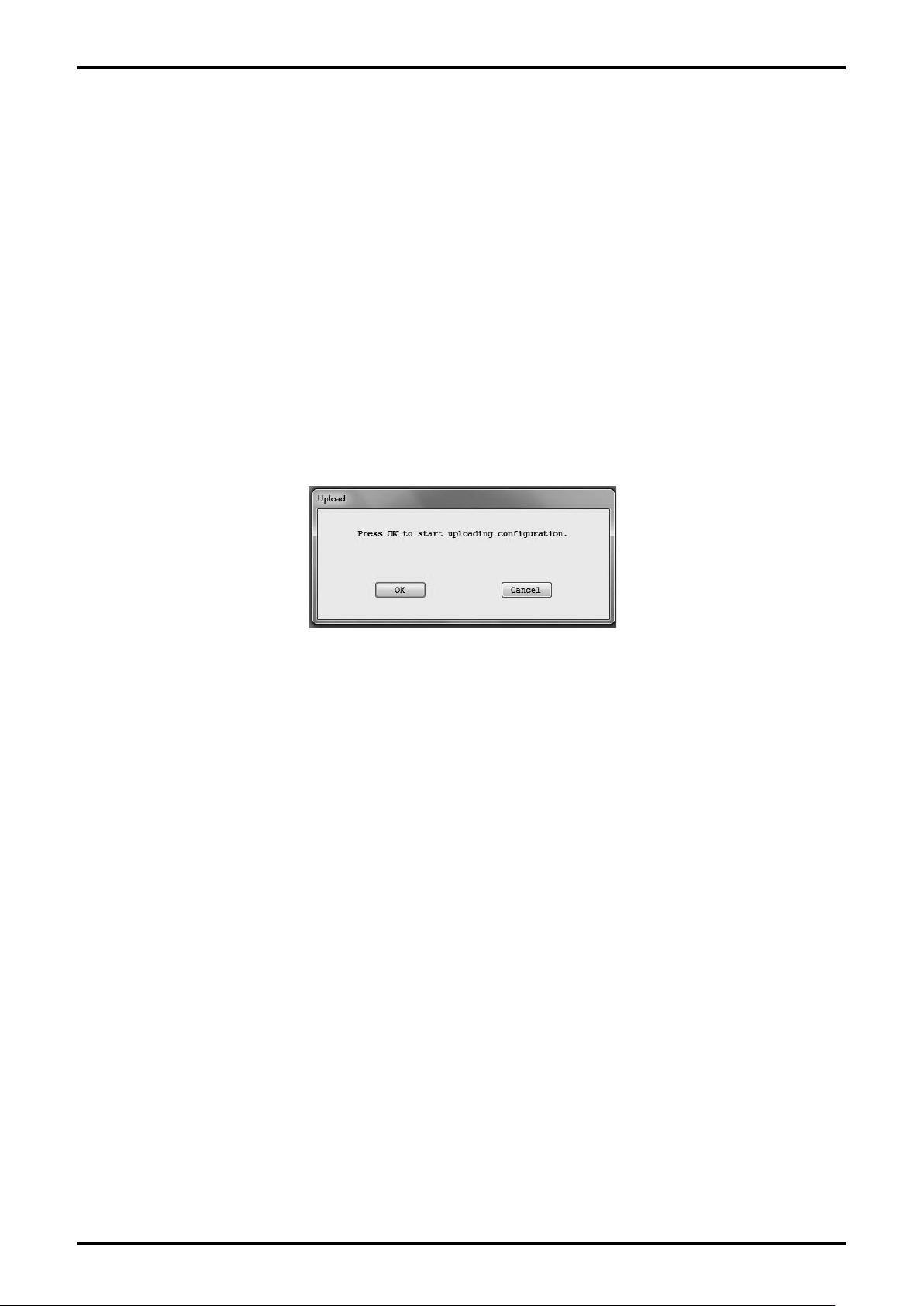
The following window (Fig. 3-85) will be displayed. To reflect the latest data, execute upload here. If it
(2)
is cancelled, the file cannot be saved.
Fig. 3-85
Page 51

E-026-3-E
(3) After the upload is completed, the dialog box shown in Fig. 3-86 will be displayed. Enter the name of
file to be saved and click "Save (S)" button.
Saving of file is completed.
a wrong destination to save the file is selected, click "Cancel" button and execute the operation
If
anew.
Click here and select
the destination to
save the file.
Enter the file name.
Click here to complete
the saving of file.
Fig. 3-86
3.10.1.3 Deleting Files
It is possible to delete data files that are no longer necessary.
(1) Click "File (F)" from the menu, and then click on "Delete File (X)" from the drop-down list of "Database
(F)".
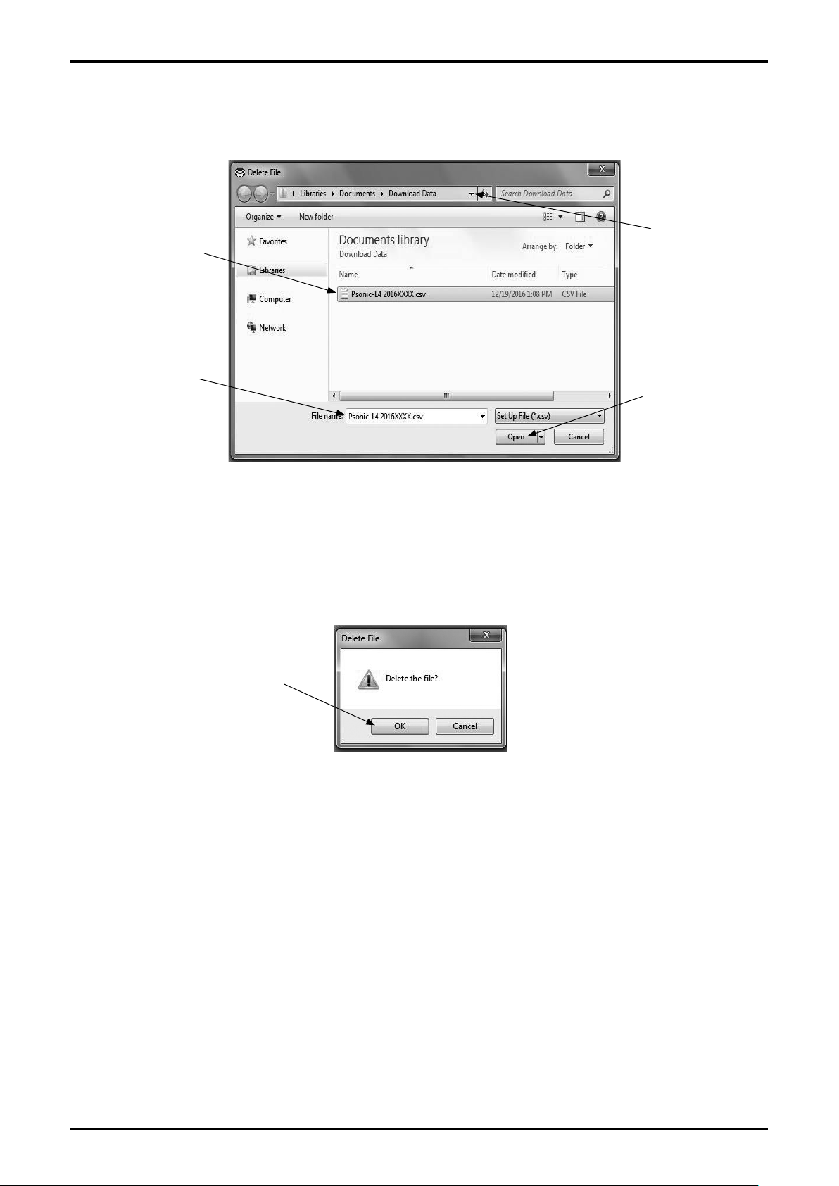
The common dialog box (Fig. 3-87) will be displayed. Select the drive and folder where the file to be
(2)
deleted is stored from the drop-down list.
51
Page 52
E-026-3-E
52
(3) Click and select the file to be deleted. Verify "File name (N)" and click "Open (O)" button. Click
"Cancel" button to exit the operation without deleting the file.
Click here and select
Click the icon of a
file to be deleted.
The file name will
be displayed.
the destination to save
the file.
Select a file and
click it.
Fig. 3-87
(4) After the click, the selected file will be opened. The message box (Fig. 3-88) will be displayed. Click
"OK" button to delete the file and click "Cancel" button not to delete the file.
By clicking "OK" button, the file will be deleted.
By clicking "OK" button,
the file will be deleted.
Fig. 3-88
3.10.1.4 Downloading
This function is used to send all the parameters from a selected file to the flowmeter transmitter. This
makes it possible to use the same parameters to set up another flowmeter transmitter (to copy settings).
If the polling address (HART poll address) of the transmitter is set other than "0", execute downloading
while communication is connected.
Before downloading, confirm the parameter currently set to the flowmeter and make sure the
(1)
flowmeter is the one suitable for this operation.
If you want to save the parameters, follow "3.10.1.2 Saving Files".
Page 53
E-026-3-E
(2) After the confirmation of flowmeter, the file to be downloaded will be read out.
(3) Click "File (F)" from the menu, and click "Download (D)" from the drop-down list of "Database (F)"
again.
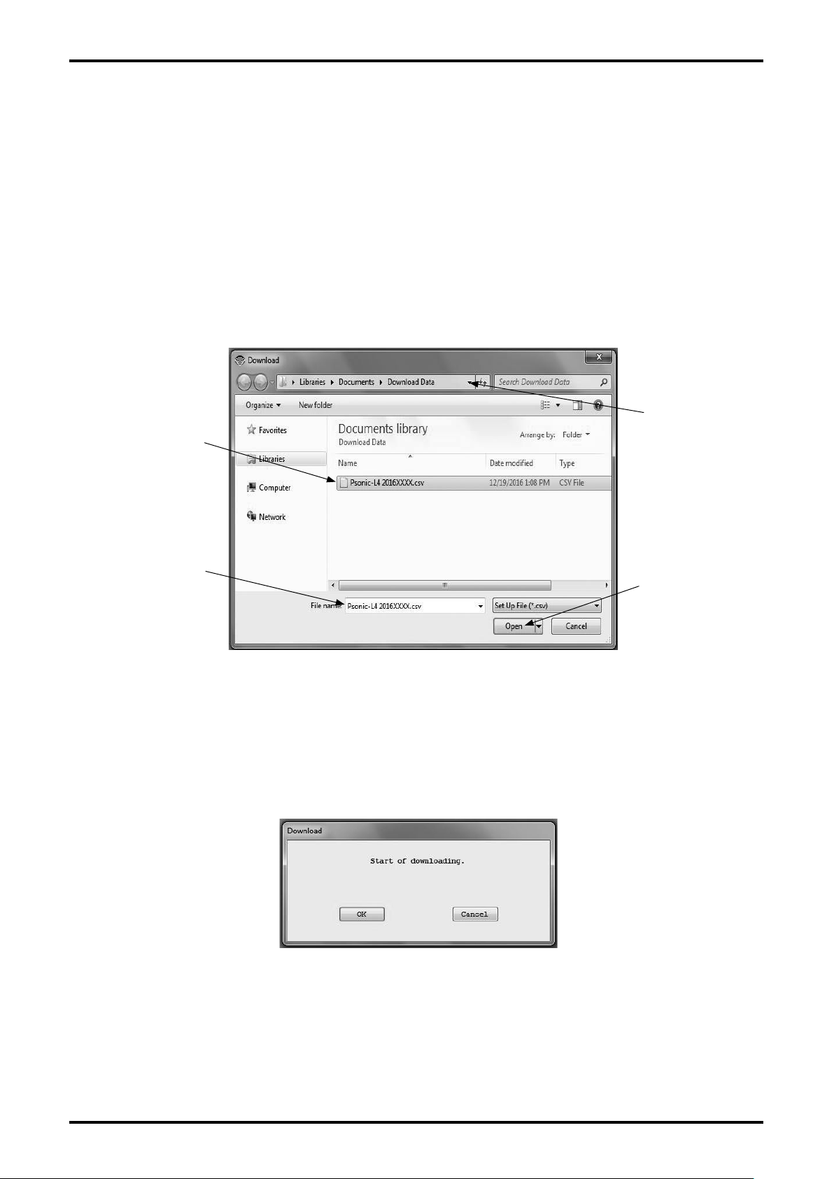
The common dialog box (Fig. 3-89) will be displayed. Select the drive and folder where the file to be
(4)
downloaded is stored from the drop-down list.
Click and select the file to be downloaded. Verify "File name (N)" and click "Open (O)" button. Click
(5)
"Cancel" button to exit the operation without downloading the file.
Click here and select
Click the icon of file
to be downloaded.
drive and folder.
The file name will
be displayed.
Select the file and
click here.
Fig. 3-89
(6) The message box (Fig. 3-90) will be displayed. Click "OK" button to download the parameters to the
transmitter.
"Cancel" button to cancel the download.
Fig. 3-90
53
Page 54
E-026-3-E
54
(7) Once the parameters are downloaded, various set values are changed and the output value from the
flowmeter is also changed. If valves are controlled by the output of the flowmeter, change the control
loop to manual control for the sake of safety, so that the control loop may not be affected by the
output of the flowmeter.
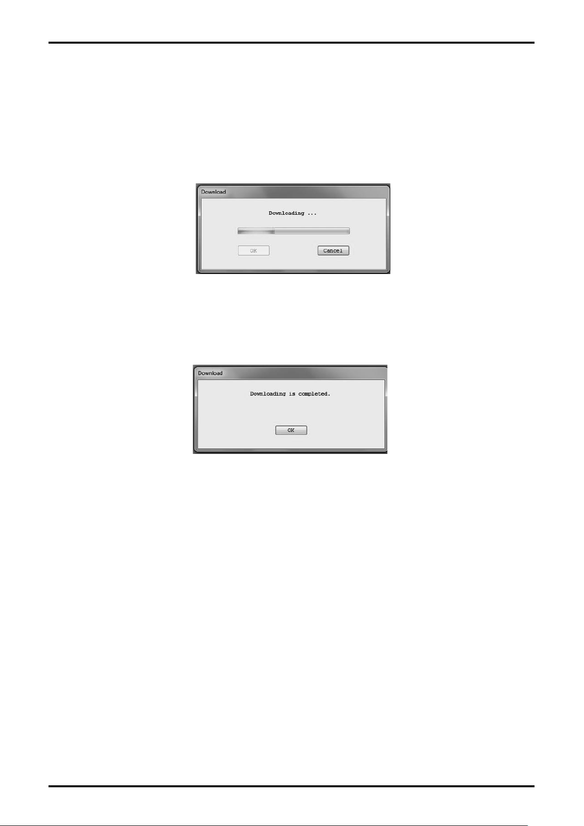
If you click "OK" button and the download is started, the message box (Fig. 3-91) will be displayed. It
(8)
is possible to confirm the status of downloading by the progress bar in the center of the window.
Fig. 3-91
Once the download is completed, a message box (Fig. 3-92) will be displayed. Click "OK" button.
(9)
Fig. 3-92
(10) Verify the downloaded content. Disconnect the communication following "3.3 Terminating the
Connection".
Next,
connect the communication following "3.2.3 Connection". Check the data is changed to the
downloaded content following "3.6 Menu: Setup (Settings)".
Page 55
E-026-3-E
3.10.2 Printing
It is possible to print a table of the transmitter's setting parameters.
(1) Click "File (F)" from the menu, and then click on "Print (P) Ctrl+P".
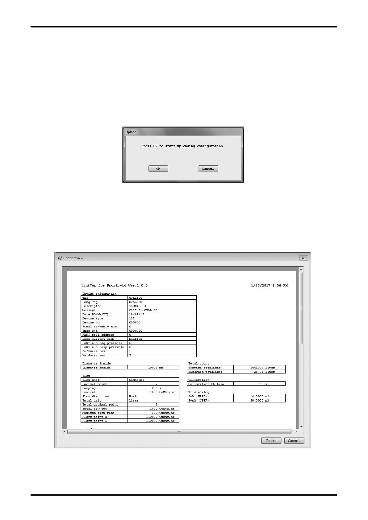
(2) The following window (Fig. 3-93) will be displayed. To reflect the latest data, execute uploading here.
If it is cancelled, the printing screen will not be displayed.
Fig. 3-93
(3) After the upload is terminated, the following window (Fig. 3-94) will be displayed. Verify parameter
values here. Click "Print" button to execute printing and click "Cancel" button not to execute printing.
The display size can be changed.
Fig. 3-94
55
Page 56
E-026-3-E
56
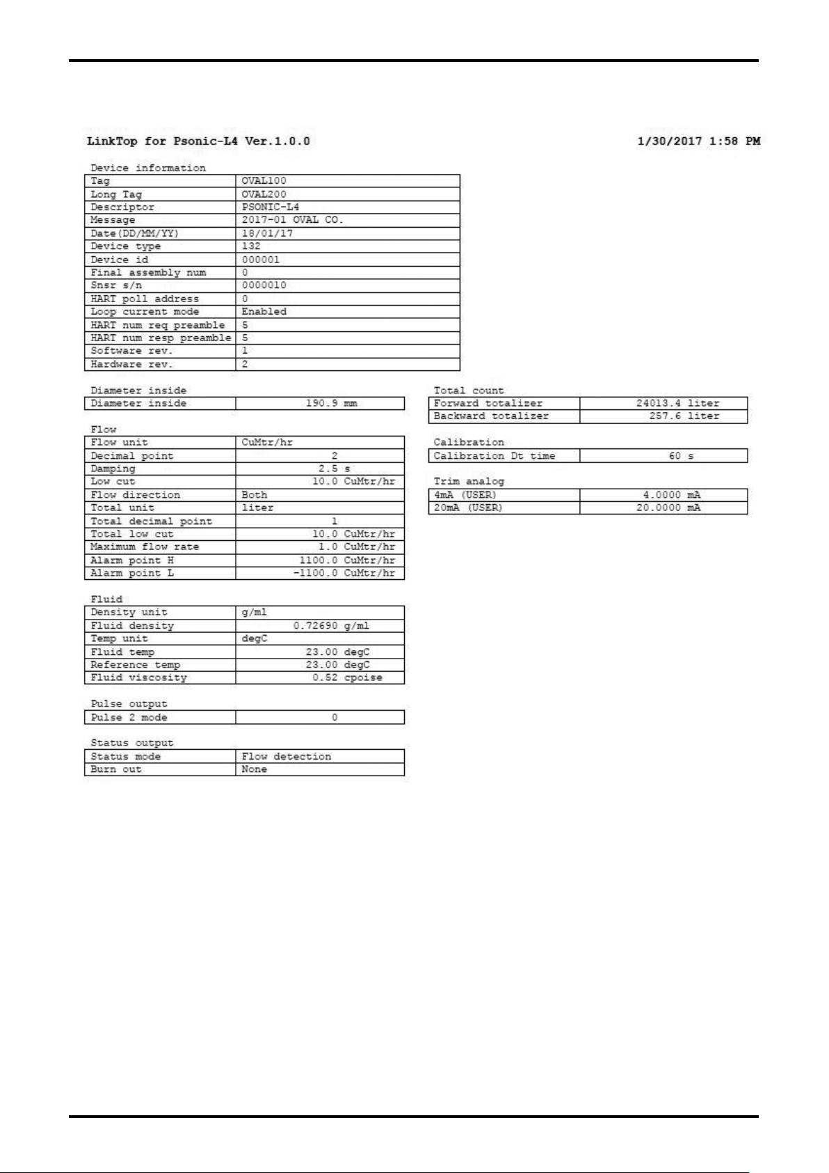
(4) By clicking "Print" button, the printing will be executed as shown in Fig. 3-95.
Fig. 3-95
(5) For the printer to be used for printing, carry out the setting by clicking "Start menu" → "Settings" →
"Control panel" → "Printer" of the used PC.
Page 57
E-026-3-E
3.11 Troubleshooting
3.11.1 If There is No Response
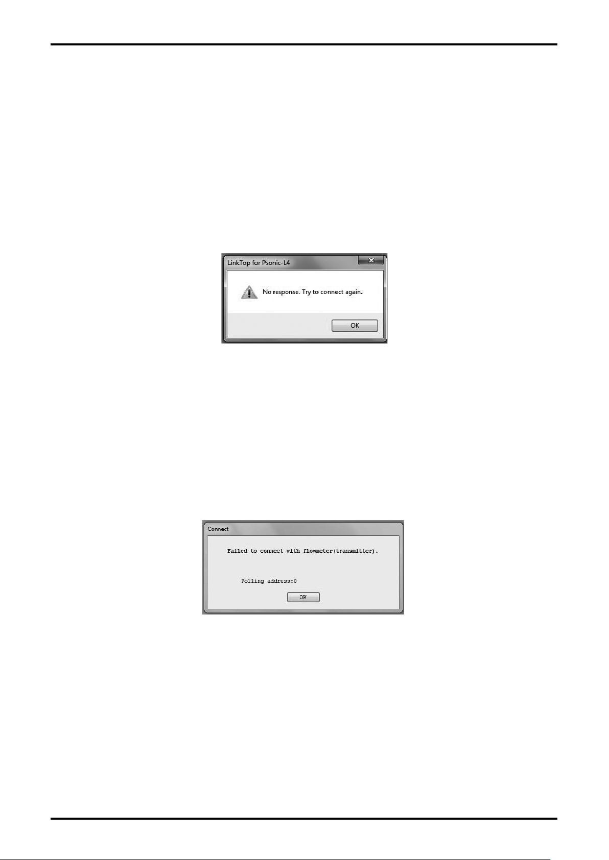
If there is a problem preventing communication between the PC and flowmeter when the flowmeter is
connected as described in section "3.2 Starting LinkTop and Connections", or while this application is
being used, then a message box will appear as shown in Fig. 3-96 . Click "OK" button if this happens,
then verify the following and try reconnecting as described in section "3.2 Starting LinkTop and
Connections":
Is the smart communication unit's probe or unit disconnected?
•
Is the flowmeter transmitter receiving power?
•
Is the polling address correct?
•
Fig. 3-96
3.11.2 If It is Not Possible to Connect to the Flowmeter
When connecting the flowmeter in "3.2 Starting LinkTop and Connections", a message box in Fig. 3-97
will be displayed if the transmitter is not supported by this application software. Click "OK" button and
make sure the type of connected transmitter corresponds to the applicable transmitter of the application
software, and then carry out the connection again following the section "3.2 Starting LinkTop and
Connections".
Fig. 3-97
57
Page 58
E-026-3-E
58
3.11.3 Input Errors
If wrong data is inputted during "Menu: Setup (Settings)" or "Menu: Diag/Service (Checking and
Adjustment)" and the communications with flowmeter transmitter are tried, an error box will appear on the
desktop as an "input error".
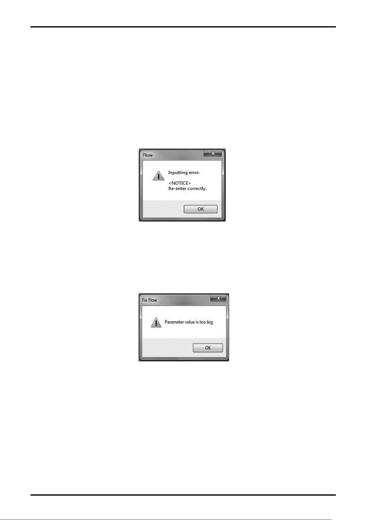
There are two types of input errors; wrong setting on LinkTop and wrong data sent to flowmeter
transmitter, which is evaluated as wrong setting on transmitter side.
After the setting item is inputted and "OK" button clicked, if the setting is evaluated as wrong setting
(1)
on LinkTop, the warning error box shown in Fig. 3-98 will appear. Click "OK" button and correct the
wrong input.
Fig. 3-98
(2) After the setting item is input and "OK" button is clicked, if the setting is evaluated as wrong setting
on transmitter side, the warning error box shown in Fig. 3-99 will appear. Click "OK" button and
correct the wrong input.
Fig. 3-99
Page 59
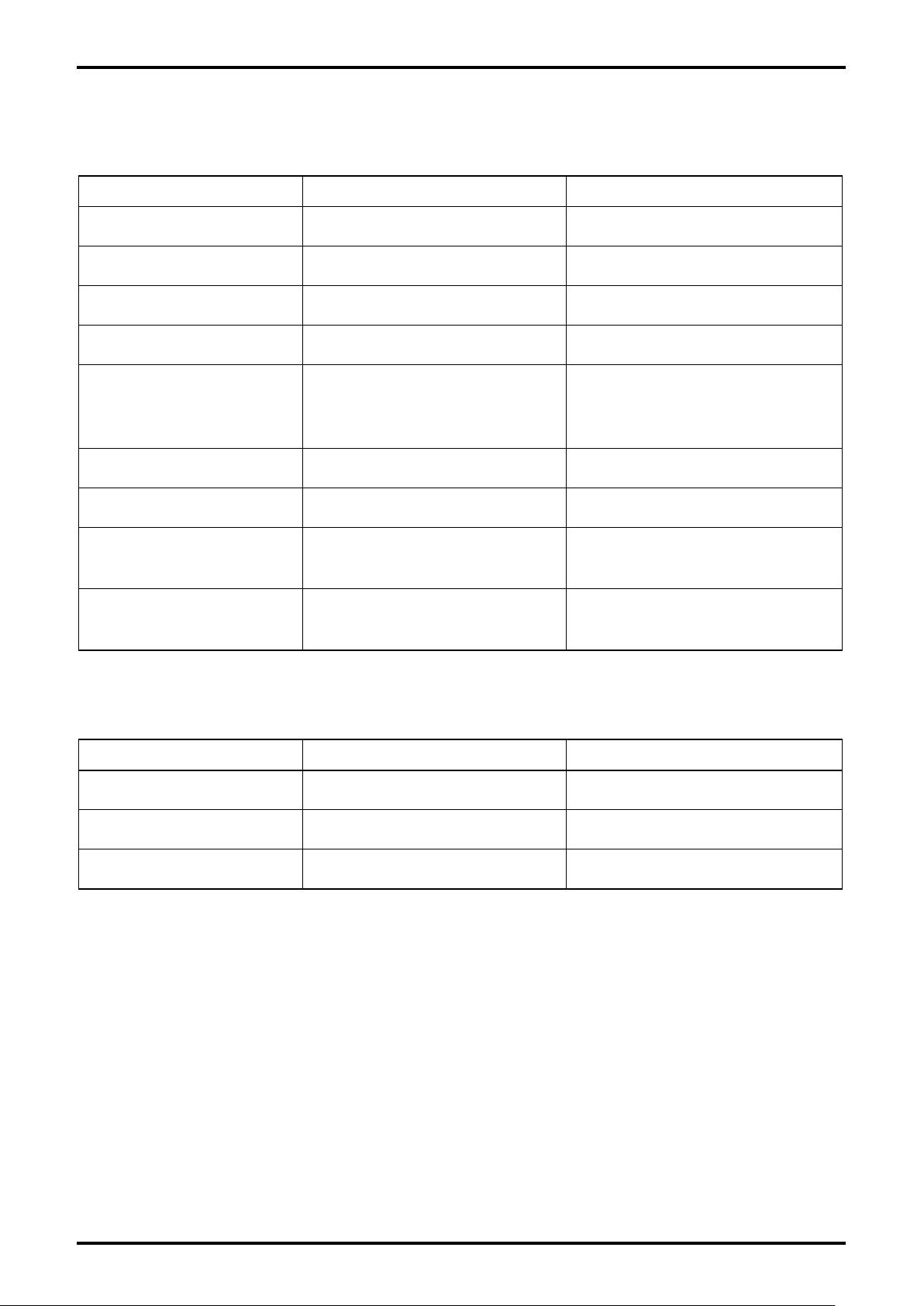
3.11.4 Error, Status Display List
Error List
Name Detail Reset condition
TX Error Transmission circuit error
RX Error Receiving circuit error
Alarm High Error Upper limit alarm
Alarm Low Error Lower limit alarm
No wave receiving error
Roff Error
Zero Offset Non Adjust Error Zero point not adjusted
Rom Check Error ROM check error
When there is no received signal for
1 measuring line or more
(sensor failure, partially filled pipe)
E-026-3-E
Unable to recover automatically due
to the hardware failure
Unable to recover automatically due
to the hardware failure
When the flow rate value falls below
the upper limit value
When the flow rate value exceeds the
lower limit value
In case of normal measurement
Implementation of zero point
calibration
Unable to recover automatically due
to the hardware failure
Asym Error
Swirl Error
Velocity distribution failure
(asymmetry)
Velocity distribution failure
(rotational flow)
Status List
Name Detail Reset condition
Simulation Active
Non-Volatile Memory Defect ROM check error
Device Configuration Locked
At execution in simulated output
mode
When the parameter write protect
SW is turned ON
When the value falls below the
criterion value of diagnosis parameter
When the value falls below the
criterion value of diagnosis parameter
Terminate the simulated output mode
Unable to recover automatically due
to the hardware failure
When the parameter write protect SW
is turned OFF
59
Page 60
E-026-3-E
60
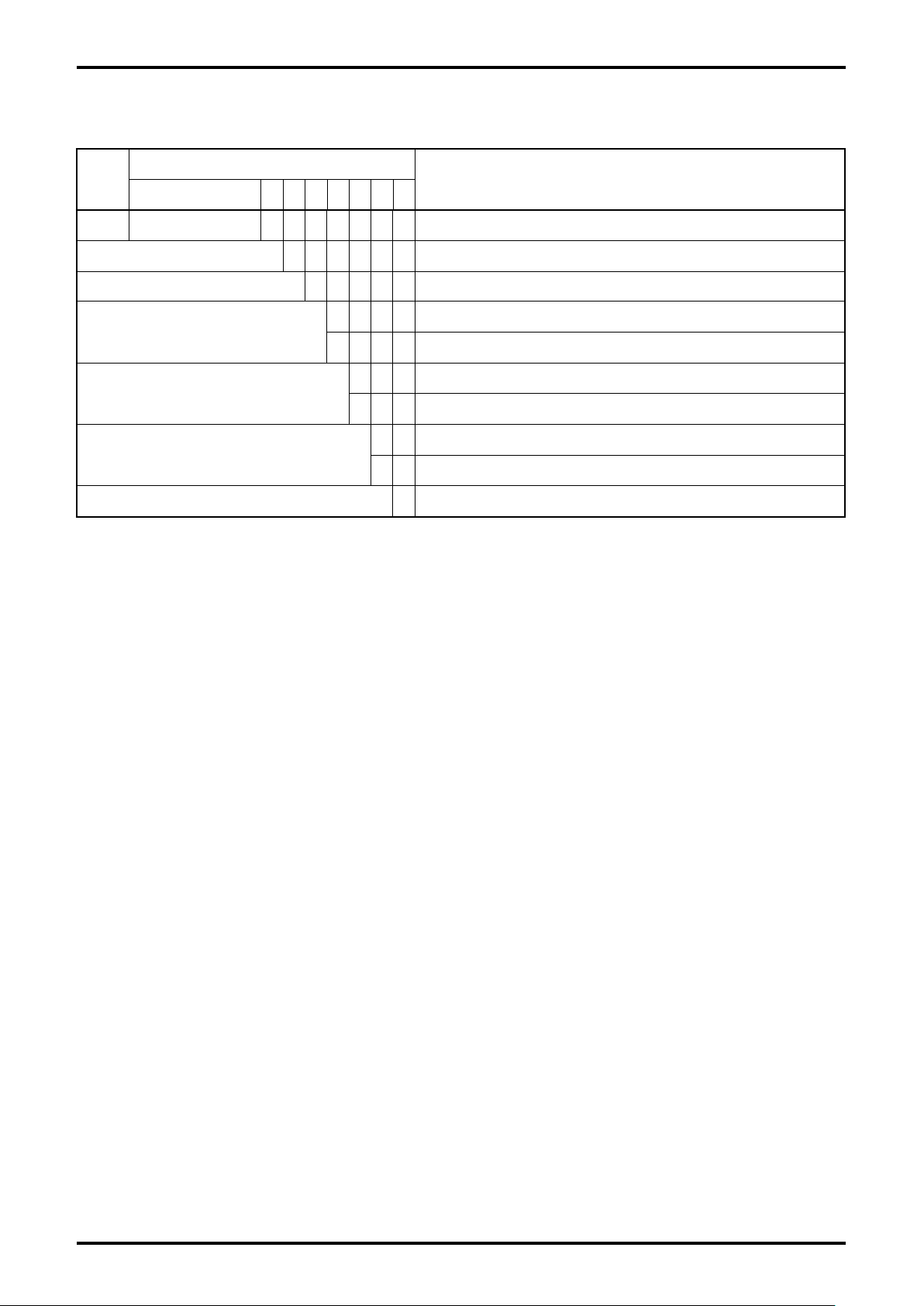
4. PRODUCT CODE EXPLANATION
Classifi-
cation
① ② ③ ④ ⑤ ⑥−⑦ ⑧ ⑨ ⑩ ⑪ ⑫
Model E L 2 3 1 0 − Smart communication unit
Power supply 0 Always "0"
Applied flowmeter D Ultrasonic flowmeter for liquid Psonic-L4
Language
Interface
Media (application software)
Symbol
Description
J Japanese (Japanese version OS supported)
E English (English version OS supported)
0 Without interface (only application software)
1 With interface (Bell 202-USB conversion)
1 CD-ROM
9 In case of other than above
0 Always "0"
Page 61
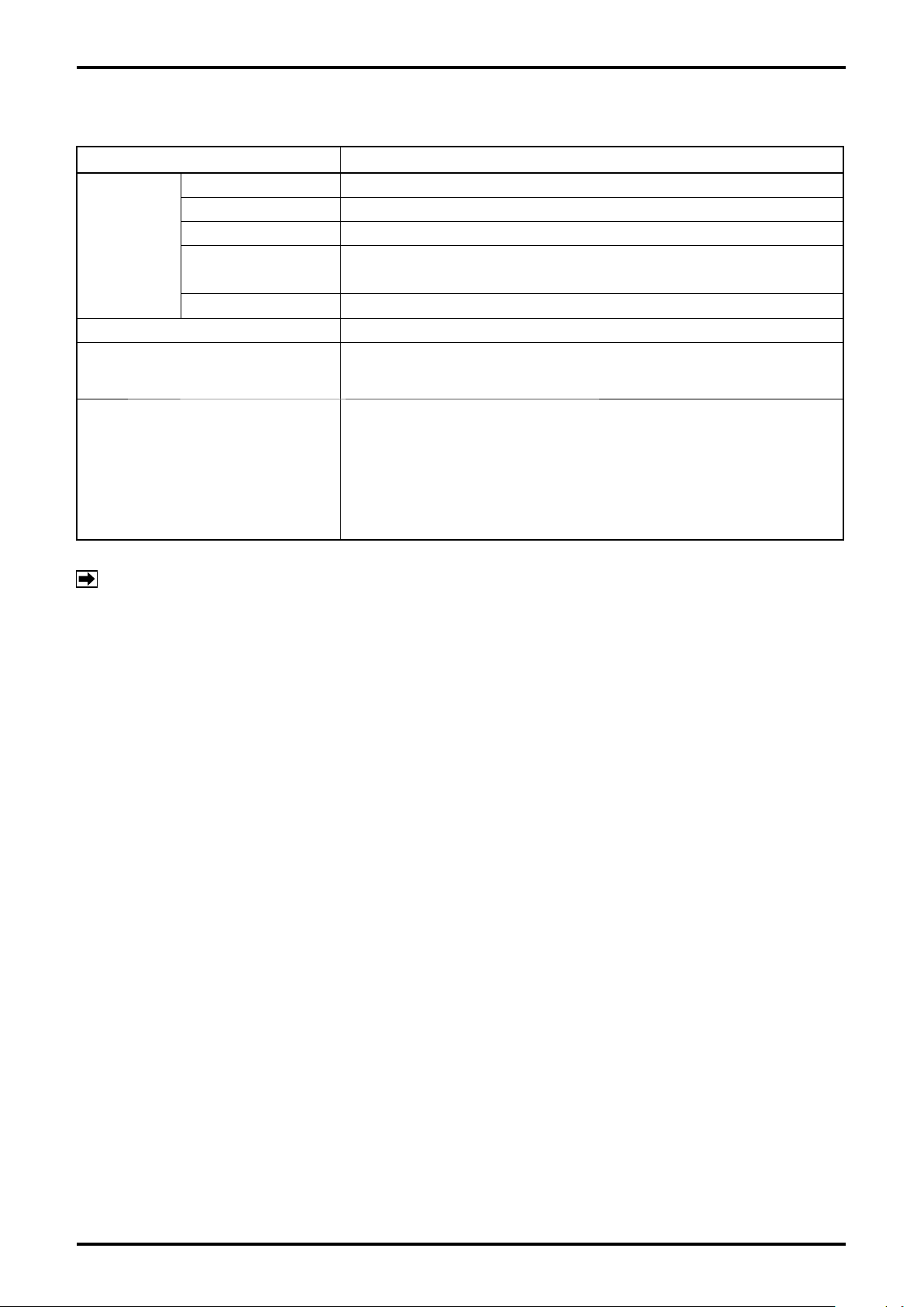
5. GENERAL SPECIFICATIONS
Item Description
Connector USB (A type)
Input/output signal Bell 202 ←→ USB
Interface
(* 1)
Communication protocol HART
Communication terminal resistance
Function
Operating temp. − 5 to +60°C
External dimensions
Housing Resin (black)
Master body: W 50 x H 20 x D 35 mm
Probe: approx. 1500 mm (fixed to interface body)
Load resistance 250Ω or more
(however, the upper limit depends on the specifications of transmitter
(flowmeter transmitter))
•
•
•
•
•
E-026-3-E
TM
protocol
Monitoring of measurement value
Reading, change of setting, and saving of parameter (location of
saving the file is FD, HD, or other external memory etc.)
Adjustment of analog output
Verification of loop of analog and pulse output
Verification of self diagnosis message
NOTE *1 : It is necessary to install the dedicated driver. (The driver software is saved in CD−ROM of
LinkTop.)
*
: Specifications of PC (operating environment)
•
PC / AT compatible machine (DOS/V)
•
Windows XP, Windows Vista, Windows 7 to 10 (English or Japanese version is supported)
OS:
The application software (LinkTop) has English OS version and Japanese OS
version.
RAM: 8MB or more
•
Hard disk: 10MB or more free space
•
Equipped with USB port
•
61
Page 62

E-026-3-E
All specifications are subject to change without notice for improvement.
2017 .04 Revised△
2016. 08 Released
E-026-3-E (1)
 Loading...