

Page 1

BATCH COUNTER
Ins. No.
E-216-5N-E
MODEL : EL1812
Every OVAL batch counter is fabricated, tested, inspected, and shipped from our factory under stringent quality
control. In order to maintain its design performance throughout its life, this manual offers the operator the
necessary installation, operation and maintenance information.
Be well familiar with these instructions before you place the counter in service and keep this manual at the field
location for ready reference.
Also refer to the instruction manual for the pulse generator (flowmeter) used.
1
Page 2

E-216-5N-E
1. BEFORE YOU BEGIN ........................................................................................ 4
1.1 Confirmation of product name plate ............................................................... 4
1.2 Transportation Considerations ....................................................................... 4
1.3 Storage Considerations ................................................................................. 4
2. GENERAL ........................................................................................................... 5
2.1 Features and Functions ................................................................................. 5
3. PART NAMES ..................................................................................................... 5
4. INSTALLATION ................................................................................................... 6
4.1 Outline Dimensions ........................................................................................ 6
4.2 Installation ...................................................................................................... 6
4.2.1 Installation Location (Indoor only) ............................................................ 6
CONTENTS
4.2.2 Panel ........................................................................................................ 6
4.2.3 Installation ................................................................................................ 6
5. WIRING .............................................................................................................. 7
5.1 Cables for Field Wiring .................................................................................. 7
5.2 Wiring Connections ........................................................................................ 7
5.3 Identifying the External Connection Terminal Block ....................................... 7
5.4 External Connection Terminals ...................................................................... 8
5.5 Flow rate input and used Terminals ............................................................... 9
5.6 Example of wire connection diagram of flowmeter signal .............................. 9
5.7 Example of Hookup ....................................................................................... 10
6. FRONT DISPLAY PART AND BATCH PROCESSING PART ............................. 12
6.1 Functions of front display part and batch processing part ............................. 12
7. BLOCK DIAGRAM .............................................................................................. 13
8. OPERATION ....................................................................................................... 14
8.1 Preparation Before Operation ........................................................................ 14
8.2 Preoperational Checks .................................................................................. 14
8.3 Operation Sequence ...................................................................................... 14
8.4 How to set the batch setting quantity ............................................................. 15
8.5 Batch processing and various functions ........................................................ 17
8.6 Alarm processing ........................................................................................... 29
2
Page 3
E-216-5N-E
9. CHANGE OF SETTING VALUE ............................................................................ 31
9.1 Parameter setting ............................................................................................. 31
9.2 Configuration of internal device ........................................................................ 35
9.3 Removal of inner assembly .............................................................................. 35
9.4 Installation of internal assembly ....................................................................... 36
9.4.1 How to assemble power supply / input board and output board ................. 36
9.4.2 How to assemble display unit ...................................................................... 36
9.5 Change of setting on input board and CPU board ............................................ 37
10. TROUBLESHOOTING......................................................................................... 38
10.1 Inspection Items .............................................................................................. 38
10.2 Q&A about Counter Behavior in Standby Mod ............................................... 39
10.3 Inspection of fuse ............................................................................................ 39
11. GENERAL SPECIFICATIONS ............................................................................. 40
12. PRODUCT SYMBOL ........................................................................................... 41
Shown in this manual are the signal words
NOTE, CAUTION and WARNING, as described in the examples below:
NOTE:
Notes are separated from the general text to bring the user’s
attention to important information.
CAUTION:
Caution statements signal the user about hazards or unsafe
practices which could result in minor personal injury or product or
property damages.
WARNING:
Warning statements signal the user about hazards or unsafe
practices which could result in severe personal injury or death.
3
Page 4
E-216-5N-E
Product
name plate
COM
1. BEFORE YOU BEGIN
This device is shipped after sufficient inspection at factory. After receiving this device, check if there is no
damage on the external appearance.
When received, it should be carefully inspected for any indication of rough handling during transit. In this section,
instructions necessary for handling this instrument are described. Make yourself familiar with these instructions.
As for other instructions, refer to respective sections.
If you have something to inquire, contact the nearest OVAL authorized service station in your district.
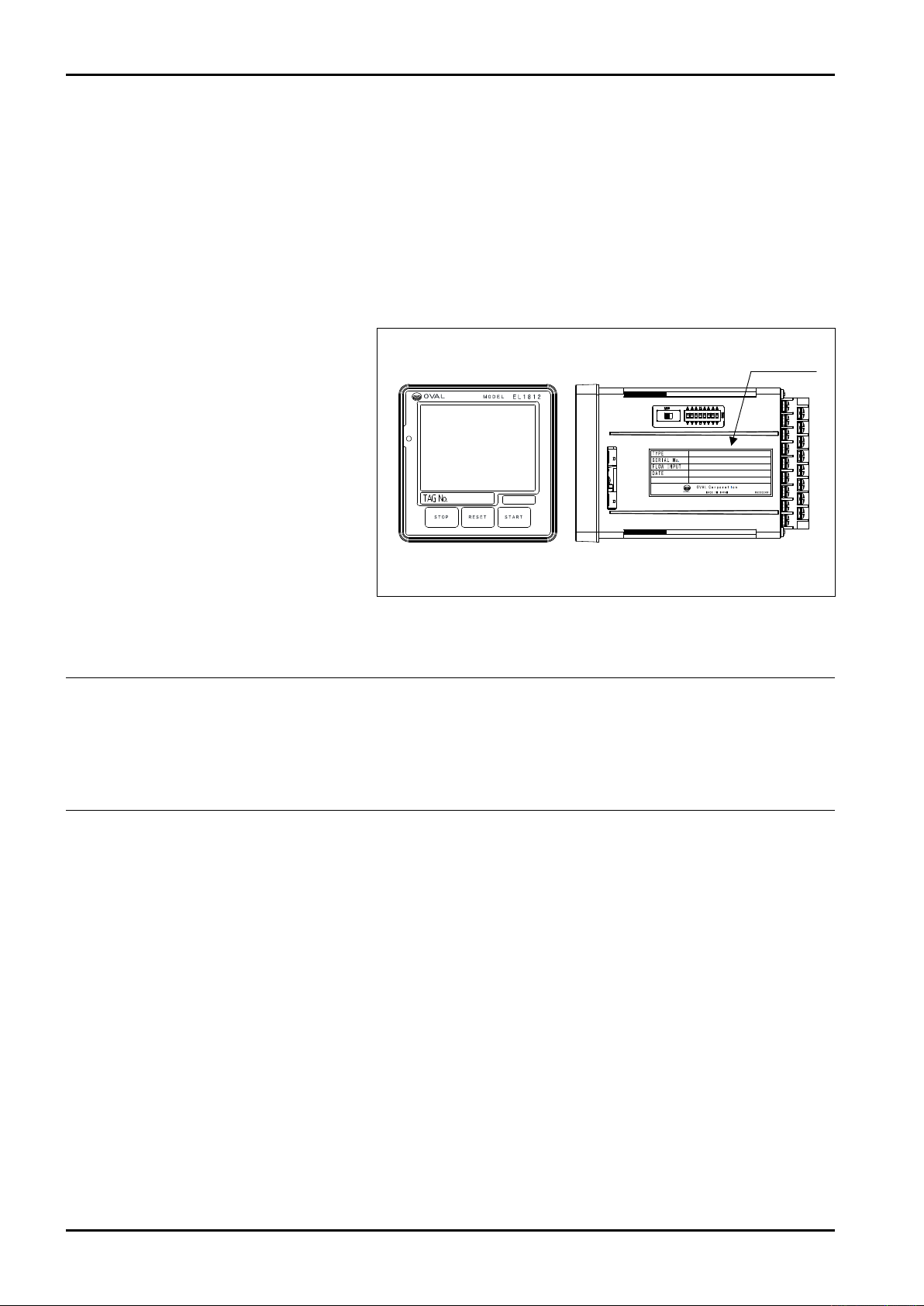
1.1 Confirmation of product name plate
This device is shipped according to the
specifications. The product name plate is
attached to the right side surface of batch
counter. Check the standard specifications and description of product number
of device correspond t o the ordered
specifications.
Fig. 1.1 Example of attachment of product name plate
◆ When you make an inquiry, please inform us of product name, product symbol (TYPE),
and production number (SERIAL No.) etc. described on the product name plate. ◆
1.2 Transportation Considerations
(1) The batch counter should be transported and stored in the same package used for transportation from our
factory if circumstances permit.
(2) Avoid giving impact shocks to the batch counter during transportation.
1.3 Storage Considerations
If the batch counter upon receipt is to be stored for extended periods of time before installation, unexpected
problems could arise. In a case like this, the following considerations should be taken:
(1) The batch counter can best be stored in the original package used for transit from the factory.
(2) Select a storage location that meets the following requirements:
• Free from rainwater and moisture
• Least vibration and impact shock
• In the room temperature and humidity environment (around 25°C and 65% R.H.)
4
Page 5
E-216-5N-E
85〜264VAC
1A
Front view
Front
display part
Push button switch
operation par t
Rear view
D-SUB connector
Externally
connected
terminal block
×2
Left side view
Fuse rating
silk
Fuse socket
Power supply
specications silk
Right side view
Input board
SW part
CPU board
SW part
Product
name plate
Terminal block
connection
diagram silk
2. GENERAL
Combined with a flowmeter and a shutoff valve, the batch counter passes a predetermined amount of the
process fluid in batching operations. Built around a single chip microprocessor, this versatile, compact, and
lightweight counter is designed for ease of operation.
It saves time and effort in many processes, such as blending materials, dosing with additives, transferring
materials from one tank to another, or shipping from an outlet, at chemical, food, paint plants or elsewhere where
streamlined production lines are desired.
2.1 Features and Functions
(1) Easy operation.
a. As setting, start, stop, and reset of batch quantity are carried out with touch panel in front of measuring
instrument and push button switches, assured operation is possible.
b.
The display part is equipped with color LCD module with 3.5-inch touch panel. Although it is small, it is easily viewable.
c.
Start and stop, and reset are operated with push button switches and setting of batch quantity is operated
with touch panel to prevent wrong operation.
(2) Wrong setting can be prevented.
As the operation of touch panel can read out nine types of batch quantities that have been registered, wrong
setting can be prevented.
(3) Correct quantitative control is possible.
a.
As an operation signal that opens or closes the valve at 2 stages, correct quantitative measurement is possible.
b.
As the overshoot quantity due to response delay of valve can be corrected by setting the forecasted overshoot
quantity, correct quantitative operation is possible.
(4) A system can be configured easily.
As start stop, and reset operations are enabled by external signal and the batch completion output can be
obtained, the interlocking with other control system is enabled easily.
(5) The safety of process can be ensured.
a.
The valve is operated by 2-stage open and 2-stage close. The generation of static electricity in piping or tank when the
operation is started is prevented and piping shock due to water hammering when the valve is closed is prevented.
b.
If a defect is generated in the process and the pulse is not input or fluid leaks exceeding the setting batch quantity, an
alarm signal will be output.
(6) This device is of high reliability and the maintenance can be implemented easily.
a. As the internal configuration is unitized, this device is of high reliability and the maintenance can be
implemented easily.
b. All I/O systems are isolated by photocoupler / relay etc.
c. When the power supply is turned OFF, total flow value and each setting value will be held in FeRAM.
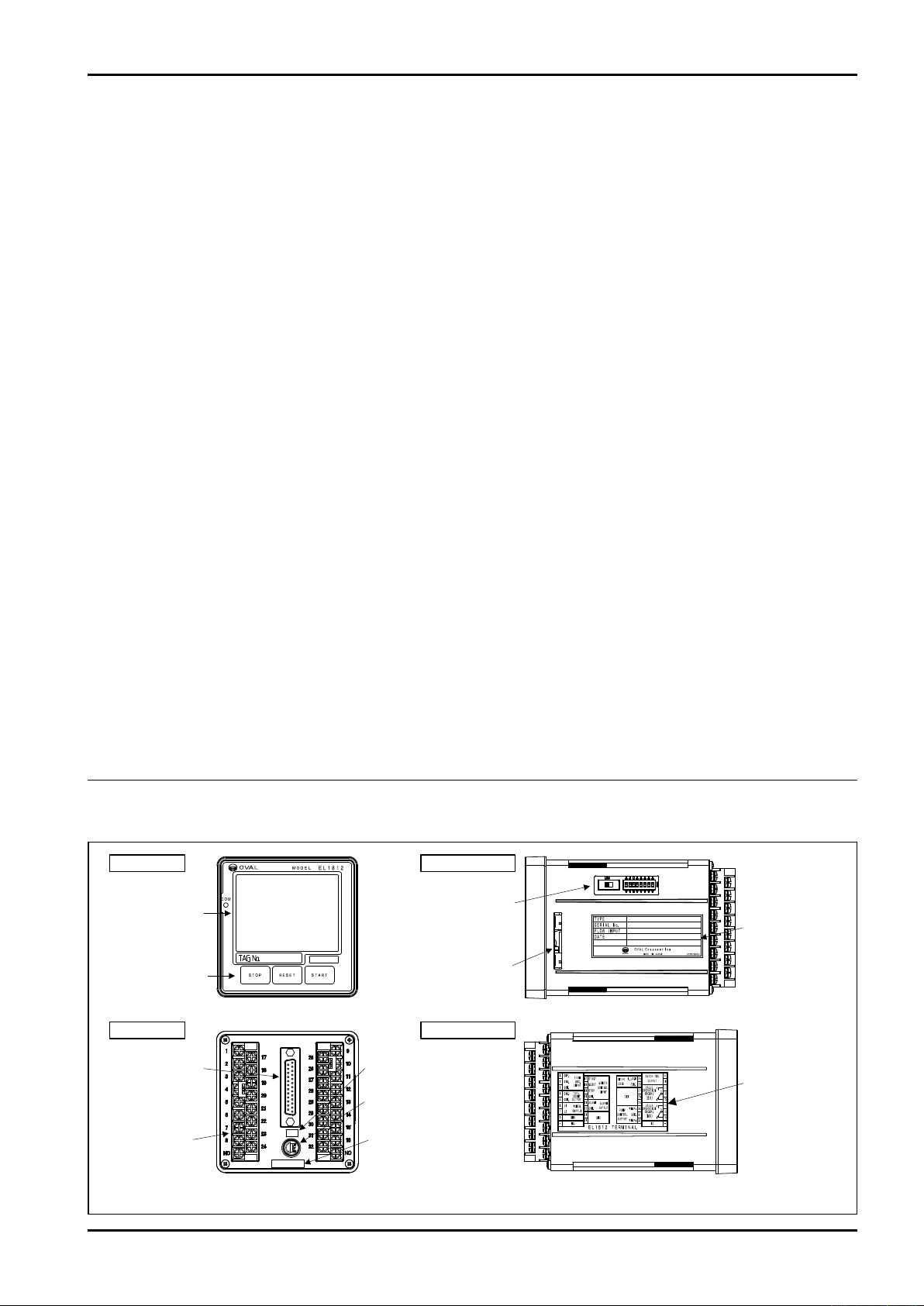
3. PART NAMES
Fig. 3.1 Name of each part
5
Page 6
E-216-5N-E
96
96
13
129.1
112
(17.1)
□91.5
Packing
COM
min.120
min.174
920.3
920.3
Panel
Batchcounter
600
1800
2200
450
Optimumrange
Availablerange
min.120
min.174
920.3
920.3
4. INSTALLATION
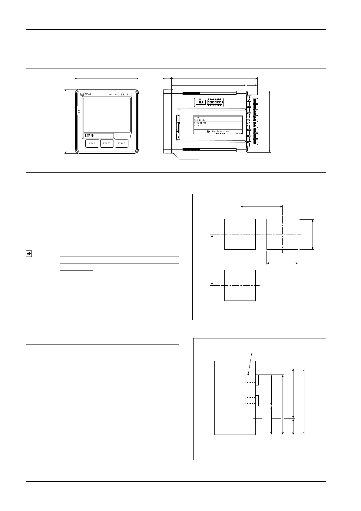
4.1 Outline Dimensions
4.2 Installation
Unit: mm
Fig. 4.1 Outline Dimensions
4.2.1 Installation Location (Indoor only)
Choose to install in the place where:
(1) Mechanical vibration, shock and corrosive gases least
exist.
(2)
The air is dry and at around room temperature and stable.
(3) A place not exposed to the direct sunlight.
(4)
A place where dust is almost none
NOTE:
1. In installation and through daily operation,
pay due care so as dust not to accumulate
in the place.
2.If chemical solvent etc. may be attached to
the front surface, it is recommended to use
the protection sheet or touch pen separately
to protect the decorative sheet on the front
surface.
Although the manufacturer g u a r a n t e e s
3.
stated
performance at ambient temperatures
from –10 to 50℃ , it is recommended that
the instrument be placed in service at room
(5)
Pr o vi de a s uf f ic i e n t wo r ki n g s pa ce be hi n d t he
temperature.
instrument – at least 50 centimeters from the back panel
of the instrument to facilitate wiring and servicing.
.
Unit: mm
Fig. 4.2 Panel Cut
Unit: mm
4.2.2 Panel
(1) Use a rigid steel sheet with a minimum thickness of
1.6 mm as min. Recommended thickness is 3.2mm.
(2) If it is required to mount the computers side by side,
dimensions in Fig. 4.2 are suggested.
(3) Recommended mounting height is given in Fig. 4.3.
4.2.3 Installation
(1)
Install the ancillary packing on the batch counter
insert it from the front surface of panel. (Fig. 4.1)
(2) Hook the enclosure hold-down fittings to the slots in
the re a r o f t he enc l o sure
instrument is positioned on a level plane, then secure
the instrument to the panel with panel mount fittings.
6
, a n d conf i r m
th a t t he
and
Fig. 4.3 Hight
Page 7
E-216-5N-E
85〜264VAC
Short-circuit board
If the interlock is not used, attach the
short-circuit board in between 25
(I.Lock) and 26 (COM.1).
D-SUB connector
Short-circuit board
If the externally operated input STOP is not
used, attach the short-circuit board in
between 19 (STOP) and 20 (COM.1).
Terminal Nos.
1 to 8, 17 to 24
Terminal Nos.
9 to 16, 25 to 32
1A
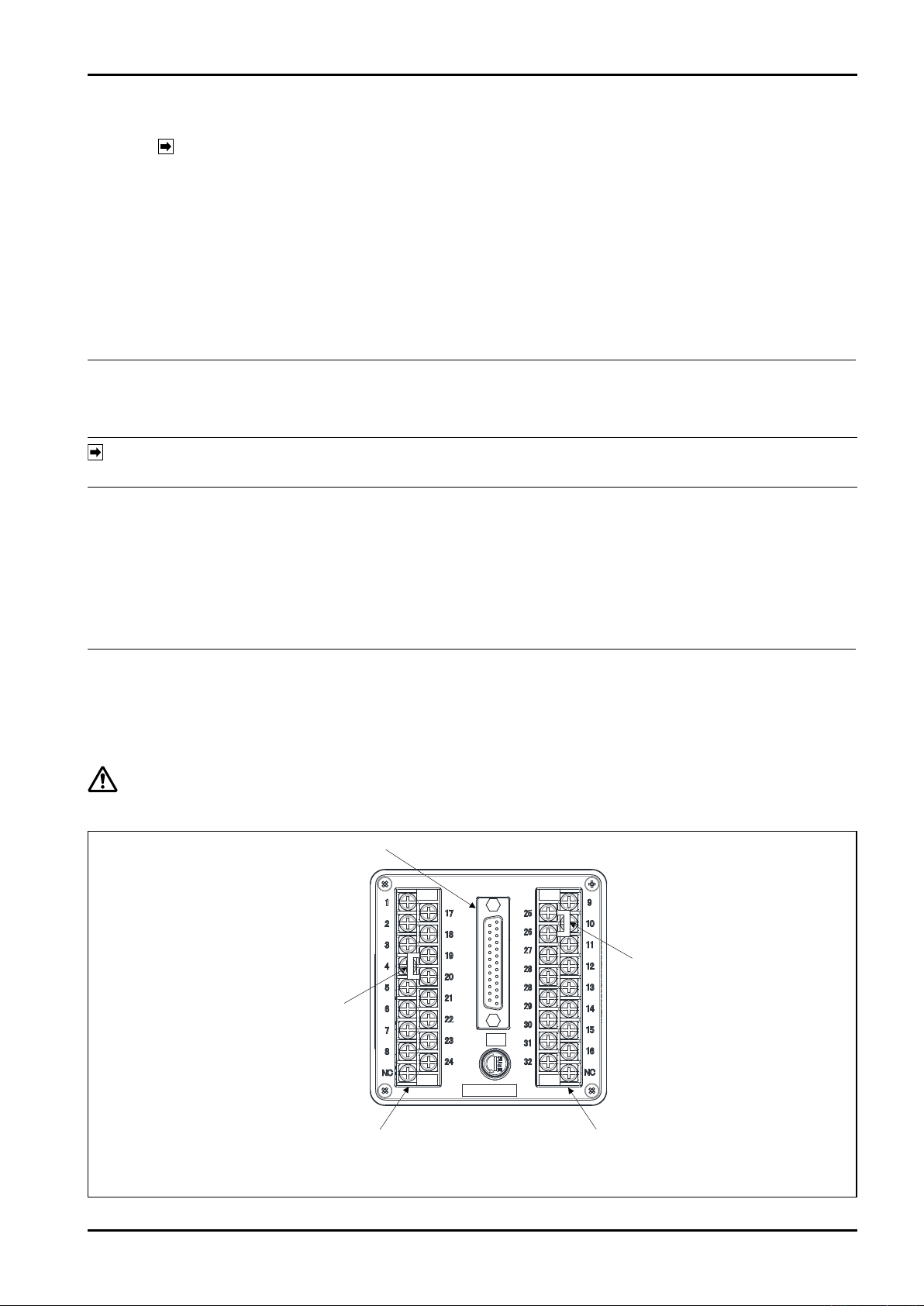
5. WIRING
NOTE: See “WIRING” in the pulse generator instruction manual.
5.1 Cables for Field Wiring
(1) For flowmeter input signal cable, electrostatically shielded, polyethylene insulated, vinyl-sheathed control
cables (CEVS, 1.25 to 2mm2, 2- or 3-conductor), or equivalent, must be used.
For output signal cables, insulated, vinyl-sheathed cables (CVV, CVVS … JIS C 3401) are suggested.
(2) Cable shields must be connected to terminal “G” of the counter. At the probe end, leave the shield wire end
unprepared.
(3) For the connection cable to D-SUB connector, use 25-pin soldering type (male). Create it as a dedicated part.
For an electric wire, use the electric wire "equivalent to UL1007, 0.5mm2 ".
5.2 Wiring Connections
(1) Conduit work is suggested for field wiring.
NOTE: In conduit work, use separate conduit for power cables and signal cables in order to minimize the
possibility of stray current pickup.
(2) Route cables sufficiently away from other power lines or power circuits, if any, to reduce the possibility of
inductive interference to a minimum.
(3) Use crimp-style terminal lugs for connections and ensure good electrical contact. Connection terminals are
found at rear of the counter (Fig. 5.1).
(4) In applications where an inductive load (valve, counter, etc.) is driven, do not fail to use a surge suppressor
(see Fig. 5.2).
(5) For the wiring, ensure approx. 30cm of allowance to enable the easy maintenance.
5.3 Identifying the External Connection Terminal Block
On the rear surface of this device, there are terminal block fixed to input board (terminals No.1 to 8, 17 to 24),
terminal block fixed to output board (terminals No.9 to 16, 25 to 32), D-SUB connector fixed to power supply
board (25-pin female).
CAUTION: Before making wiring connections, verify the validity of flowmeter (pulse generator) and receiving
instrument combination by referring to their product No., tag No., etc.
Fig. 5.1 External wire connection terminal diagram
7
Page 8
E-216-5N-E
Signal DescriptionNo
Flow rate
input
SUP.
SIG.
COM.1
COM.2
L1
L2
GND1
NC
NC
START
RESET
STOP
COM.1
ALARM
COM.5
I.Lock
COM.1
PUMP
Select 1
PUMP
COM.6
END
END
SV a
COM.3
SV b
MV a
COM.4
MV b
SIG.
1
Signal DescriptionNo
9
Select 2
10
Select 4
11
Select 8
12
SET
13
COM.1
24
GND2
25
2
3
5
6
7
8
−
−
17
18
19
20
21
22
23
24
25
26
27
28
29
30
32
31
9
10
11
12
13
14
15
16
4
Pulse output
Power supply
Batch
completion
output
External
operation
input
Alarm output
GND1
GND1
Interlock
Pump
operation
signal
External CH.
input
Valve
operation
signal (SV)
Valve
operation
signal (MV)
Contact pulse/
open collector
Open collector output
85 to 264VAC 50/60Hz
Connection terminal (※2)
No-contact relay output contact Form "a" contact
External CH. input shielded grounding ※ Not conducted with GND1
1
2
3
4
5
6
7
8
17
18
19
20
21
22
23
24
25
26
27
28
29
30
31
32
25
13
12
11
10
9
24
−
9
10
11
12
13
14
15
16
−
Output board side
17P M3.5
Input board side
17P M3.5
D-SUB connector
Female 25P
(※1)
Terminal block
D-SUB connector female 25P
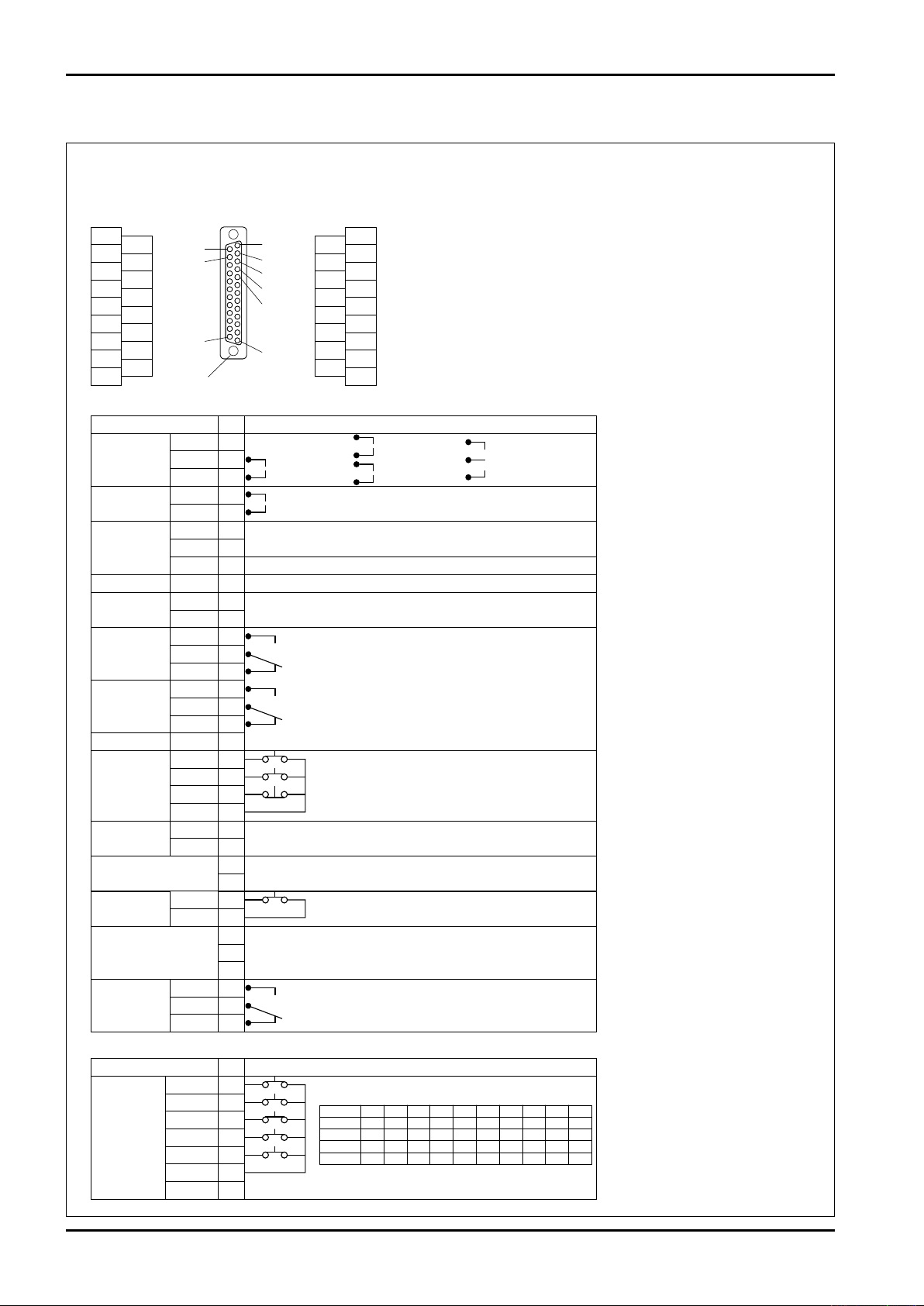
※ Each COM.1 terminal is conducted.
Each GND1 terminal is conducted.
※2: Grounding of equipment
Be sure to ground it to prevent electric shock/
fire and block external noise.
※1: D-SUB connector type
DBLC-J25SAF-23L6E
Japan Aviation Electronics Industry, Limited
※3: To use the external operation input, it is
necessary to prepare the connector of
D-SUB25 pin by yourself and connect the
circuit for selecting a channel to D-SUB
terminal on the rear surface of this machine.
※ The frame of D-SUB connector is
conducted with GND1.
※ External operation and batch setting volume
For "preset value" setting, refer to section 8.4.
Limit flow rate signal 1-stage open
Relay contact Form "c" contact
Relay contact Form "a" contact
Shielded grounding
Shielded grounding
Upper limit flow rate signal fully opened
STOP is short-circuited when it is not used
(※3)
Interlock is short-circuited when it is not used
Pump control output Relay contact Form "c" contact
Combination of select and CH.
Select 1
Select
2
Select
4
Select
8
CH.1 CH.2 CH.3 CH.4 CH.5 CH.6 CH.7 CH.8 CH.9 CH.F
ON OFF ON OFF ON OFF ON OFF ON OFF
OFF ON ON OFF OFF ON ON OFF OFF ON
OFF OFF OFF ON ON ON ON OFF OFF OFF
OFF OFF OFF OFF OFF OFF OFF ON ON ON
2-wire current
pulse (4/20mA)
3-wire voltage
pulse (PG30)
2-wire current
pulse (PG30S)
4-40-inch screw
14
1
5.4 External connection terminals
●
Terminal block and D-SUB connector
8
Page 9
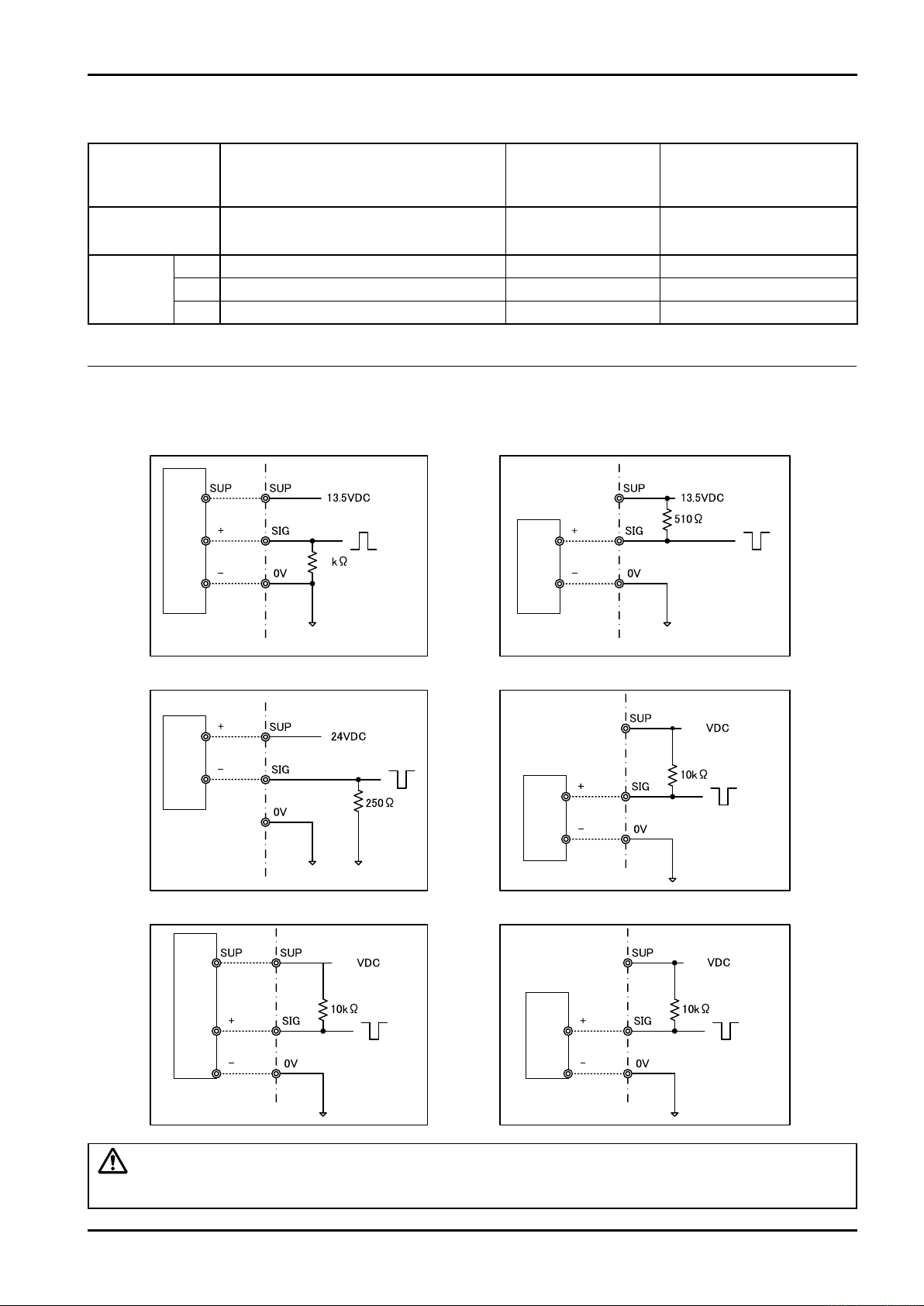
5.5 Flow rate input and used terminals
12VDC3-wiretypevoltagepulse(PG30) 12VDC2-wiretypecurrentpulse(PG30S)
24VDC2-wiretypecurrentpulse(4/20mA)
33
13.5
13.5
13.5
3-wiretypeopencollector
Opencollector
Contactpulse
Pulse
generator
Pulse
generator
Pulse
generator
Pulse
generator
Pulse
generator
Pulse
generator
E-216-5N-E
Signal type
Transmitter
Contact-closure pulse / 2-wire voltage pulse
Open collector pulse 12VDC 2-wire type
current pulse
PG20, Coriolis flowmeter
PG30S
24VDC 2-wire type
Current pulse
PA14, 15, 25
NPG60A
1 - ○ + ○ SUP.
Terminal
2 ○ + ○ - ○ SIG.
3 ○ -
-
○mark: used terminal
5.6 Example of wire connection diagram of flowmeter signal
3-line type open collector
3-wire voltage pulse
PG30, NPG60A
flow pet
○ COM.
CAUTION: In the wiring, connect the wires properly, while checking the combination of product number
and measuring instrument number etc. of flowmeter (transmitter) and receiver.
9
Page 10
E-216-5N-E
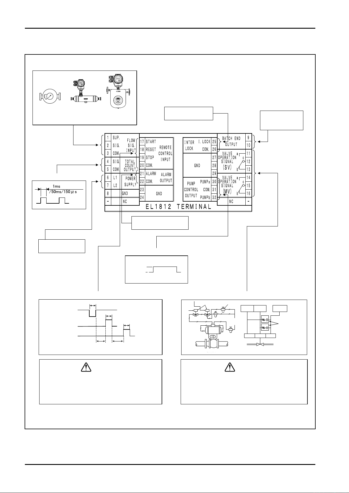
IftheexternaloperationinputSTOPisnotused,
STOP(19)toCOM.(20)shouldbealwaysshortcircuited.Iftheinterlockisnotused,I.LOCK(25)
toCOM.(26)shouldbealwaysshort-circuited.
Terminal connection diagram
(silk on left side of this device)
Output to remote totalizer
counter, etc.
Open collector
200msec.min.
200msec.min.
200msec.min.
200msec.
min.
200msec.
min.
Power: 85 to 264VAC
50/60Hz
Operation
Stopped
STOP (contact b)
RESET (contact a)
START (contact a)
Alarm output LED lamp etc.
can be driven
Pump can be operated /
stopped for batch
processing
CORIOLIS FLOWMETERS
OVAL FLOWMETER
ALTImass Type S
ALTImass Type U
ULTRA
MK
Flow signal input.
(std.)
Pump output
SV MV COM
SV
MV
COM
Valve
R
C
R
C
Surgesuppressor
Air
supply ?
Combinationfilter/reducingvalve
Two-stage shuto valve
3-wayDirectionalvalve
Valve operation output
Remote Control Input
Short-circuited when
an interlock is not used
Function such as LED
light up when batching
completes is enabled
Output to External Totalizer
OVAL owmeters,
Coriolis owmete rs,
etc.
CAUTION:
* The owme ter sh own h ere
is a n exa mple.
Itisrecommendedtoattachthesurgesuppressoretc.totheinductionloadsidetoprotectthe
contact.
CAUTION:
5.7 Example of Hookup
Fig. 5.2 Exampl of Wiring Connections (Terminal block)
10
Page 11
E-216-5N-E
Selector1
Selector2
Selector4
Selector8
SET
COM.1
GND2
Selector1
Selector2
Selector4
Selector8
CH.1
ON
OFF
OFF
OFF
CH.2
OFF
ON
OFF
OFF
CH.3
ON
ON
OFF
OFF
CH.4
OFF
OFF
ON
OFF
CH.5
ON
OFF
ON
OFF
CH.6
OFF
ON
ON
OFF
CH.7
ON
ON
ON
OFF
CH.8
OFF
OFF
OFF
ON
CH.9
ON
OFF
OFF
ON
CH.F
OFF
ON
OFF
ON
9
10
11
12
13
24
25
25
24
13
12
11
10
9
Rearsurfaceofenclosure
D-SUBconnector
Eachselection
(contacta)
SET
(contacta)
200msecormore
HeldbyONorOFF
Pushbuttonswitchetc.
(forfixingCH.)
Selectorswitch
(forselectingCH.)
Fig.5.3 Example of Hookup(D-SUB connector)
11
Page 12
E-216-5N-E
Status display part
Integration display part
Batch quantity setting value
display part
Valve / pump
status display part
LCD module communication
monitoring part
Batch processing part
(push button switch)
Setting button part
Channel display part
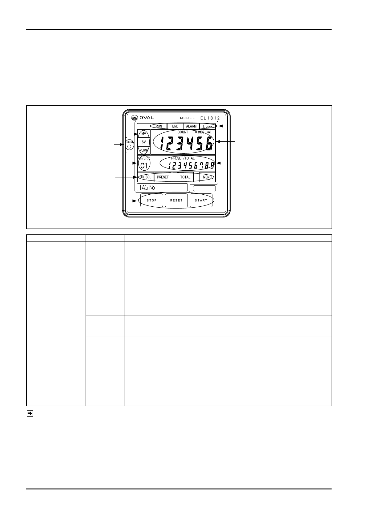
6. FRONT DISPLAY PART AND BATCH PROCESSING PART
6.1 Functions of front display part and batch processing part
The display part has status indication lamps such as RUN and END. There are integration display, batch quantity
setting value, and channel display part in the center of upper stage. There are operation indication lamps of valve
and pump on the left side. The batch processing part has three push button switches; START, STOP, and RESET
and the control at batch processing is enabled only by three push button switches.
Status display part
Valve / pump
status display part
LCD module communication
monitoring part
Integration display part
Batch quantity setting
value display part
Channel display part
Setting button part
Batch processing part
(push button switch)
Fig. 6.1
Name Function
RUN
END Lights up when the batch is completed: green
ALARM Lights up when an alarm is generated: red
I.Lock Lights up when the interlock signal is turned ON; batch is enabled when it is turned ON: blue
MV Upper limit flow rate signal lights up when it is turned ON; goes out when it is turned OFF: red
SV Restricted flow rate signal lights up when it is turned ON; goes out when it is turned OFF: red
PUMP Pump control signal lights up when it is turned ON; goes out when it is turned OFF
COM Communication status between CPU board and LCD module can be monitored: blue LED
COUNT Batch quantity total flow value display 6 digits
Measurement unit
Integrated flow Displayed when any - (- blank), mL, L, kL, m3, g, kg, t, USG, barrel is set
PRESET Batch setting quantity display 6 digits
TOTAL Displays the total value by touching TOTAL button 9 digits *1
CH. No. Displays the selected channel number 2 digits *2
ERR. CODE Displays error number when an alarm is generated *3
CH.SEL Shifts to [CHANNEL SELECT] screen
PRESET Shifts to [PRESET SETTING (CH.F)] screen only when CH.F (free) is selected
TOTAL Displays the total value by touching the button
MENU Shifts to [MENU] screen
STOP Batch processing temporarily stops when an alarm is generated: buzzer stops
RESET Bach completion is reset when an alarm is generated: alarm is reset
START
Displays the batch processing status ; lights up when batch operation is ongoing; blinks when
the operation is interrupted: yellow
Displayed when any of ×1000, ×100, ×10, ×1, ×0.1, ×0.01, ×0.001 is set
Batch processing starts when the operation is temporarily stopped: batch processing is restarted
NOTE: *1: Displayed while you touch the TOTAL button. Display time can be set by setting parameter.
*2: Channel display *3: Error display
12
C1: channel 1 C6: channel 6 E1: pulse non-receipt alarm
C2: channel 2 C7: channel 7 E2: overrun alarm
C3: channel 3 C8: channel 8 E3: leak alarm
C4: channel 4 C9: channel 9 E4: interlock alarm
C5: channel 5 CF: free setting channel E5: emergency stop by RESET button
In case of external setting, C is displayed in small letter E7: WDT reset alarm
Front setting: C1 to CF E8: electric power failure alarm
External setting: c1 to cF E9: FeRAM alarm
Page 13
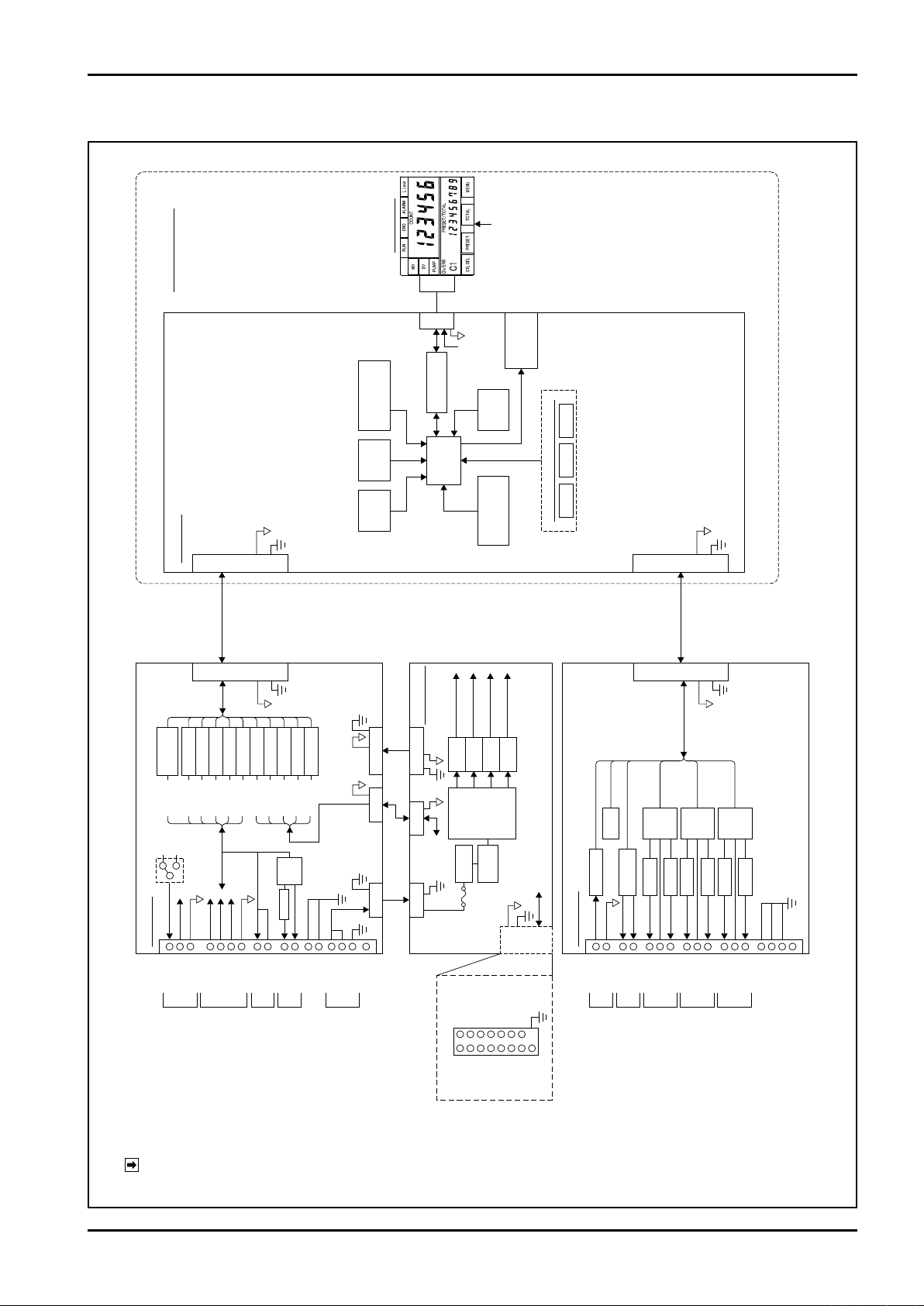
7. BLOCK DIAGRAM
External line
terminal block
External line
terminal block
Flow rate input
Interlock
Batch completion
output
Valve operation
output SV
Valve operation
output MV
Pump output
Form "c" contact
Power supply
for transmitter
+13.5V
+24V
Pulse output
External operation input
Alarm output
Form "a" contact
Supplied power AC
Input board
SUP. 1
I. Lock 25
COM.1 26
END 9
SV a 11
SV b 13
COM.3 12
MV a 14
MV b 16
COM.4 15
PUMP 30
PUMP 32
GND1 27
GND1 28
GND1 29
NC
COM.6 31
END 10
SIG. 2
COM.1 3
SIG. 4
COM. 2 5
ALARM 21
COM. 5 22
GND1 23
L1 6
L2 7
GND1 8
NC
GND1 24
START 17
RESET 18
STOP 19
COM.1 20
2 RXD
3 TXD
7 VD_G
9 select 1
10
select
2
11
select
4
TXD+ 14
TXD− 15
RXD+ 16
RXD− 17
VD_+ 18
COM.1 24
GND2 25
Frame
grounding
12
select
8
13 SET
SIG.
Pulse input
circuit
Photocoupler
START
RESET
STOP
SIG.
ALARM
Select 1
Select 2
Select 4
Select 8
SET
Photocoupler
Photocoupler
Photocoupler
Photocoupler
Photocoupler
Photocoupler
Varistor
Buzzer
Relay
Photo MOS
Photocoupler
Photocoupler
Photocoupler
Photocoupler
Connector
ConnectorConnector
Connector Connector
Varistor
Varistor
a
COM
Relay
AC/DC
Power supply
Input: 24VDC
D−
SUB
Noise
filter
Connector
CPU
debug
circuit
WDT
reset
circuit
CPU
Electric power
failure detection
circuit
Serial
interface
Connector
Connector
Connector
Connector
Connector
Connector
Select 1, 2, 4, 8
SET,
Communication
Select 1, 2, 4, 8
SET
Select 1, 2, 4, 8
SET
+24V,
+
13.5V,
+
5V,
+
5V
F
CPU board
Display unit
Output board
Operation buttons on front surface
Touch operation input
LED module
Power supply board
D−SUB 25P
+24V
+13.5V
circuit
+5V
circuit
+5V
circuit
Photocoupler/relay
Power supply for
transmitter
Power supply for
transmitter
LED module
Power supply for
internal control
85 to 264V
Varistor
Varistor
Varistor
Varistor
Varistor
Relay
Relay
SIG. IN
START, RESET, STOP
SIG. OUT, ALARM
Select 1, 2, 4, 8, SET
+24V,
+
5V,
+
5V
I.Lock
END
SV, MV, PUMP
Buzzer
+
24V,
+
5V
Communication
circuit
STOP RESET START
FeRAM
circuit
LED module
communication
monitoring LED
+5V
+5V communication
※1
※1
E-216-5N-E
NOTE:
Fig. 7.1 Block
※1: To use the external operation input, it is necessary to prepare the connector of D-SUB25 pin by yourself
and connect the circuit for selecting a channel to D-SUB terminal on the rear surface of this machine.
13
Page 14
E-216-5N-E
CAUTION:
CAUTION:
8. OPERATION
8.1 Preparation Before Operation
(1) Make sure to see that the counter and associated equipment are correctly installed, connected and wired with
no place left unfinished.
Make sure to see that the power terminals are connected to a source of the rated voltage.
Connecting an incorrect power voltage source may ruin the counter.
(2) Make sure that the shutoff valve is correctly wired and set. For details, see the instruction manual for the
shutoff valve.
8.2 Preoperational Checks
In the state the fluid does not flow erroneously, check the constant flow valve surely operates as in the
procedure shown below (conduct this as daily routine before starting operation).
(1) Supply power to this device.
(2) Enter some arbitrarily set quantity of a batch.
(3) Press START button and check the constant flow valve can open.
(4) Press STOP button and check the constant flow valve can close.
(5) Repeat steps (3) and (4) above several times to make certain that the shutoff valve opens and closes
properly.
(6) If the counter features remote start and stop, repeat steps (3), (4) and (5) above also at the remotely located
point.
8.3 Operation Sequence
(1) Turn on power.
(2) Enter some arbitrarily set quantity of a batch. See Section 8.4
(3) Press RESET button and reset the batch quantity total flow value.
(4) Press START button to start the operation. Then, this device will execute the quantitative operation.
(5) To measure the previous batch setting quantity again, press RESET button to reset the total flow value and
press START button. Then, it will be measured again.
NOTE: If the batch setting quantity is different, set the batch setting quantity in each case.
(6) To stop the operation temporarily, press STOP button. Then, the constant flow valve will be fully opened.
To restart the operation, press START button. The measurement will be continuously restarted from the
stopped point.
To stop the operation, press STOP + RESET buttons after temporary stop.
If even one pulse is input in this device until START button is pressed after RESET button
is pressed, the operation cannot be started.
14
Page 15
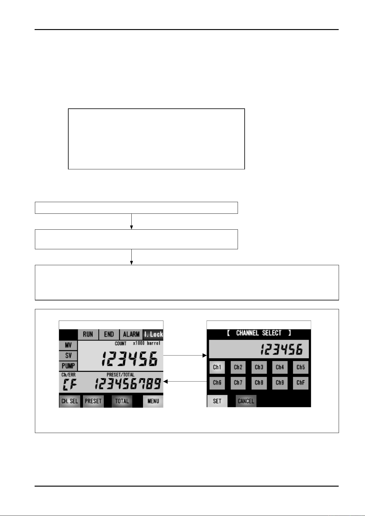
8.4 How to set the batch setting quantity
There are two methods for setting the batch setting quantity as shown below.
(1) Select the memorized batch setting quantity from [CHANNEL SELECT] screen.
CH.1 to 9 fixed batch setting quantity
(2) Select an arbitrary batch setting quantity from [PRESET SETTING] screen.
CH.F arbitrary batch setting quantity
Register the fixed batch setting quantity preliminarily by setting parameter.
Conditions und er which the setti ng of batch setting
quantity cannot be changed:
If the conditions shown below are formed, the setting is
disabled.
(1) When an alarm is generated
(2) When the batch completion is output
(3) During batch processing
How to set the fixed batch setting quantity
●
E-216-5N-E
Touch CH.SEL button on [BATCH PROCESSING] screen
Shift to [CHANNEL SELECT] screen
Select CH.1 to 9 (desired fixed batch setting quantity)
Select CH.1 to 9 and touch SET button. The batch setting quantity will be memorized and the screen
will shift to [BATCH PROCESSING] screen. If you touch CANCEL button, the changed data will be
deleted and the screen will shift to [BATCH PROCESSING] screen (cancelled). The setting will be
memorized in the batch setting quantity until the next change.
[BATCH PROCESSING] screen [CHANNEL SELECT] screen
"CH.SEL"
"SET"
"CANCEL"
Fig. 8.1 [BATCH PROCESSING] screen ⇔ [CHANNEL SELECT] screen
15
Page 16
E-216-5N-E
●
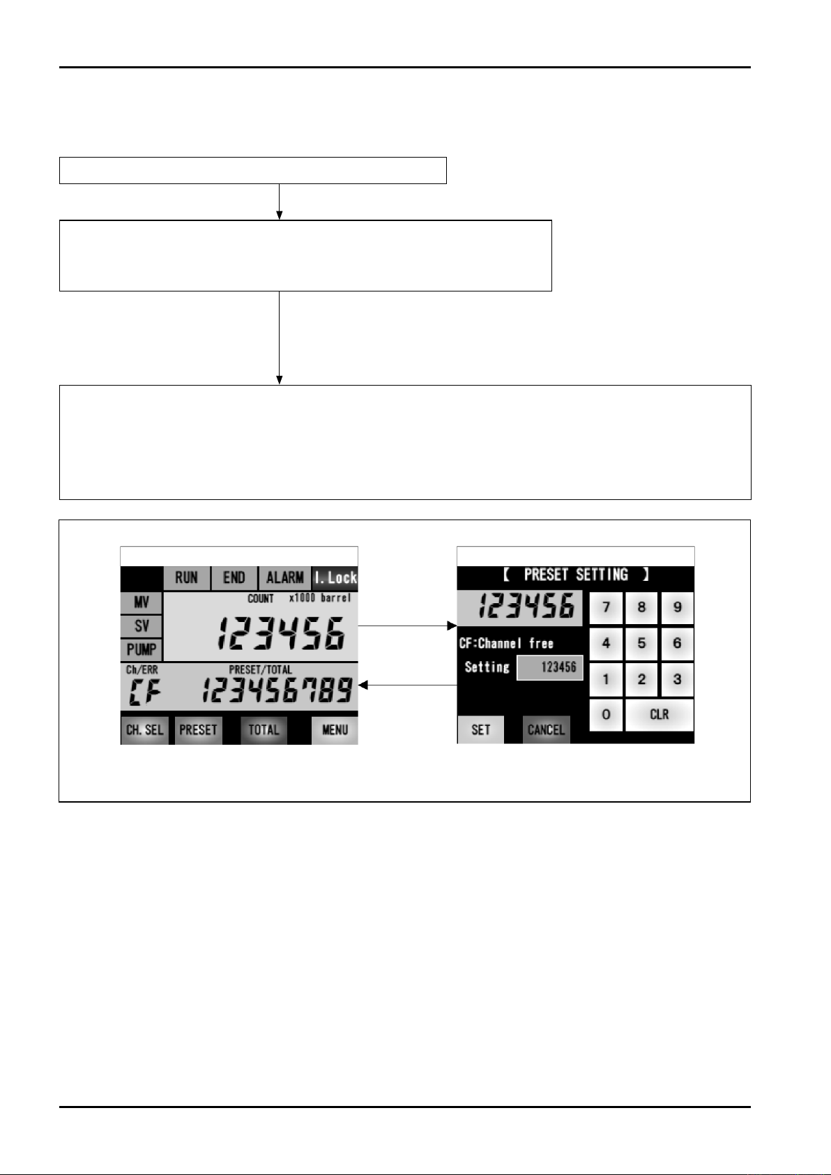
CH. F arbitrary batch setting quantity
Carry out the setting following the flow shown below.
Touch PRESET button on [BATCH PROCESSING] screen
Shift to [PRESET SETTING] screen (*1)
Clear the current value by touching CLR button and change the
batch setting quantity from a numeric keypad
(*1) If the channel selection is other than
CF or cF, the screen does not shift
to [PRESET SETTING] screen even
if you touch the PRESET button.
Set the desired batch setting quantity and touch SET button.
The batch setting quantity will be memorized in CH.F and the screen will shift to [BATCH
PROCESSING] screen. If you touch CANCEL button, the changed data will be deleted and the
screen will shift to [BATCH PROCESSING] screen (cancelled). The data will be memorized in
CH.F until the next change.
[BATCH PROCESSING] screen [PRESET SETTING] screen
"PRESET"
Only CF and cF
"SET"
"CANCEL"
Fig. 8.2 [BATCH PROCESSING] screen ⇔ [PRESET SETTING] screen
16
Page 17
E-216-5N-E
F
A
B
C
D
E
Interlock signal
I.Lock lamp
START button
Pulse input
RUN lamp
Pump control signal
PUMP lamp
SV: Restricted ow
rate signal
SV lamp
MV: Upper limit ow
rate signal
MV lamp
Batch completion signal
END lamp
Flow rate
Time
Leakmonitoring
zone
Non-reception
monitoringzone
Restrictedflowrateopen
Upperlimitflowrateopen
Excessivefilling
monitoringzone
If the interlock signal is
not turned ON, the
lling is not started.
Turned OFF by turning
ON the RESET button
When MV is turned OFF,
the buzzer is turned ON
for 0.5sec three times
Buzzer is turned
ON for 5sec after
completion time
Pump output delay timer*
Leak monitoring zone
Forecasted overrun
quantity*
Completion
monitoring time
setting value*
Overrun
quantity*
Terminal setting value*
Batch setting quantity*
*Parameter setting
Initial setting value*
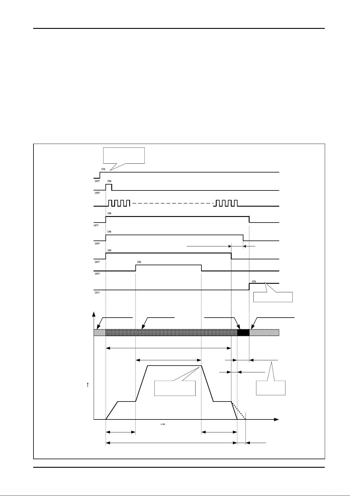
8.5 Batch processing and various functions
(1) Usual operation
At the same time when START button is pressed, the valve is opened to the predefined aperture. If a constant
quantity of fluid flows (initial setting value = from point A to point B), the valve will be fully opened.
If the measurement up to point C is completed, the valve will be automatically closed and kept to predefined
aperture.
If the fluid reaches point D, the stop signal will be transmitted, however, the valve will be actually closed at point
E because the valve operation will be delayed.If the value is integrated up to batch setting volume, the
completion monitoring timer operates and outputs the completion signal after the monitoring time is over. If the
value is totalized up to batch setting volume, the completion monitoring timer operates and outputs the
completion signal after the monitoring time is over. If the totalized value exceeds the point F within the completion
monitoring time, the overrun alarm will be output.
The adjustment of aperture from valve A to B and C to D should be preliminarily set on valve side.
Fig. 8.3
17
Page 18
E-216-5N-E
START button
STOP button
RUN lamp
Pump control
signal
PUMP lamp
SV: restricted ow
rate signal
SV lamp
MV: upper limit ow
rate signal
MV lamp
Batch
completion
signal
END lamp
Flow rate
Time
Forecasted
overrun quantity*
Completion
monitoring time
setting value*
Terminal
settingvalue*
*Parametersetting
Initial
settingvalue*
Batch setting quantity*
Pump output delay timer
Pump output delay timer
Blinks
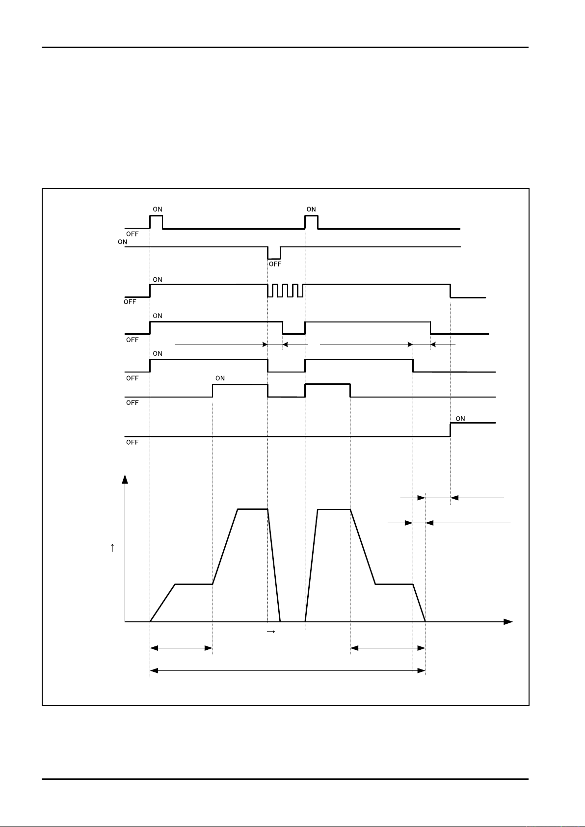
(2) Temporary stop operation
If you press STOP button, SV/MV output will be turned OFF and the operation will be temporarily stopped. PUMP
output will be stopped after delay timer.
If you press START button, the operation will be restarted.
If the operation is temporarily stopped at upper limit flow rate, both of SV and MV will be turned ON at the restart
and the flow rate will reach the upper limit flow rate (not becomes 2-stage open).
If the operation is temporarily stopped at restricted flow rate, only SV will be turned at the restart and the flow rate
will reach the restricted flow rate.
18
Fig. 8.4
Page 19
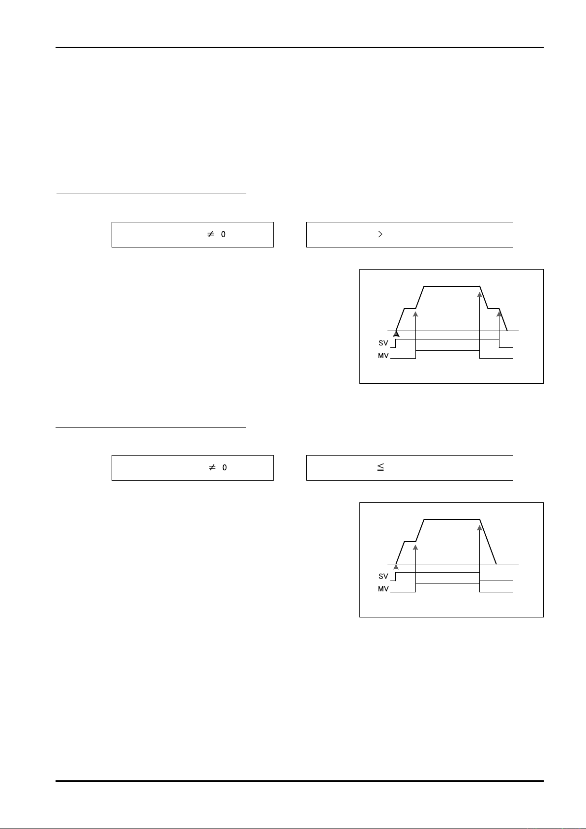
(3) Batch processing setting
Initial setting and Final setting Forecasted overrun quantity
Initial setting and Final setting Forecasted overrun quantity
and Forecasted overrun quantityInitial setting Final setting
The batch processing enables five patterns of batch processing with four parameters shown below.
・Initial setting value
・Terminal setting value
・Batch setting quantity
・Forecasted overrun quantity
Each pattern is shown below.
Pattern 1 2-stage open 2-stage close
If the conditions shown below are formed
Operation
(1) If you press START button, SV output will be turned ON
(2) If "cumulative total quantity" reaches "initial setting value", MV
output will be turned ON
(3) If "cumulative total quantity" reaches "batch setting quantity -
terminal setting value", MV output will be turned OFF
(4) If "cumulative total quantity" reaches "batch setting quantity -
forecasted overrun quantity", SV output will be turned OFF
E-216-5N-E
Pattern 2 2-stage open 1-stage close
If the conditions shown below are formed
Operation
(1) If you press START button, SV output will be turned ON
(2) If "cumulative total quantity" reaches "initial setting value", MV
output will be turned ON
(3) If "cumulative total quantity" reaches "batch setting quantity -
forecasted overrun quantity", MV/SV output will be turned
OFF
Fig. 8.5
Fig. 8.6
19
Page 20
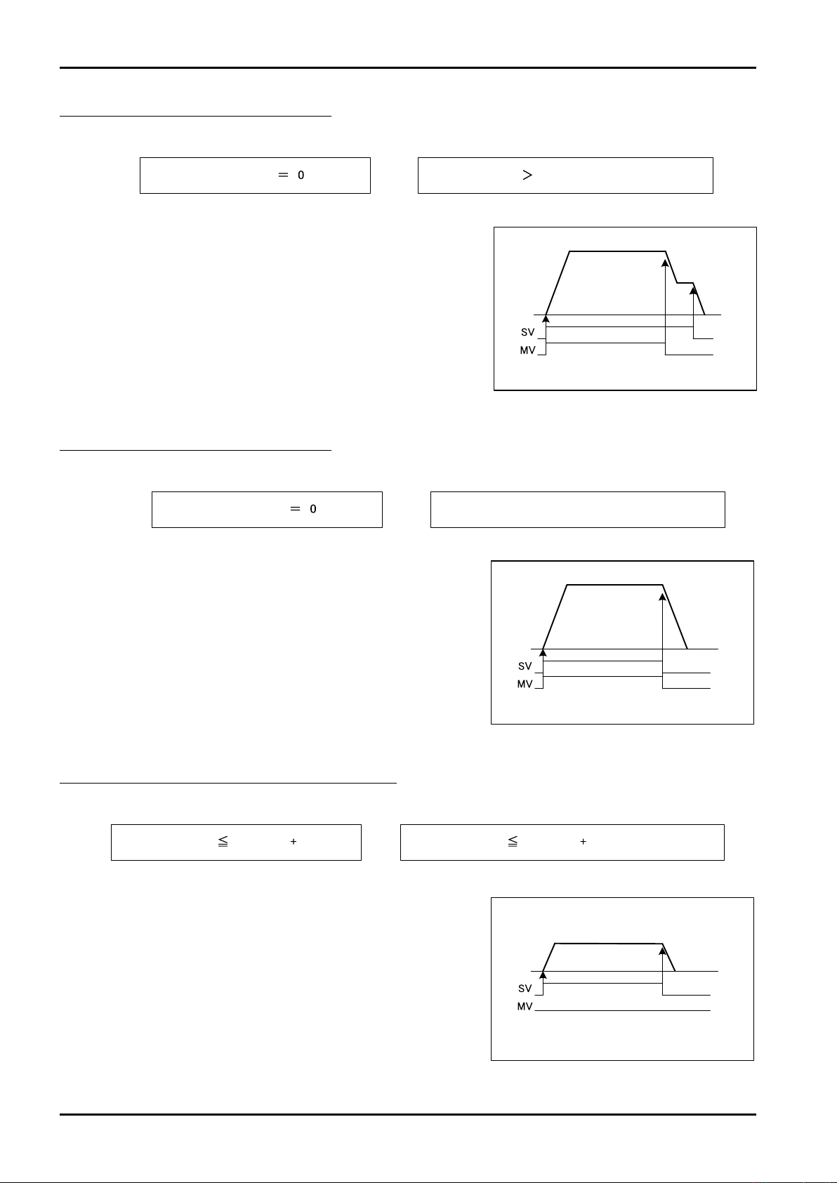
E-216-5N-E
Initial setting and
Final setting
Forecasted overrun quantity
Final setting ≦ Forecasted overrun quantity
Initial setting and
Initial setting and
Final setting
Forecasted overrun quantity
Final setting ≦ Forecasted overrun quantity
Initial setting and
Initial setting and
or
Initial settingBatch setting quantity
Final setting
Final setting Initial settingBatch setting quantity Forecasted overrun quantity
Forecasted overrun quantity
Pattern 3 1-stage open 2-stage close
If the conditions shown below are formed
Operation
(1) If you press START button, SV/MV output will be turned ON
(2) If "cumulative total quantity" reaches "batch setting quantity -
terminal setting value", MV output will be turned OFF
(3) If "cumulative total quantity" reaches "batch setting quantity -
forecasted overrun quantity", SV output will be turned OFF
Pattern 4 1-stage open 1-stage close
If the conditions shown below are formed
Fig. 8.7
Operation
(1) If you press START button, SV/MV output will be turned ON
(2) If "cumulative total quantity" reaches "batch setting quantity -
forecasted overrun quantity", MV/SV output will be turned
OFF
Pattern 5 1-stage open 1-stage close (only SV)
If the conditions shown below are formed
Operation
(1) If you press START button, SV output will be turned ON
(2) If "cumulative total quantity" reaches "batch setting quantity -
forecasted overrun quantity", SV output will be turned OFF
Fig. 8.8
20
Fig. 8.9
Page 21
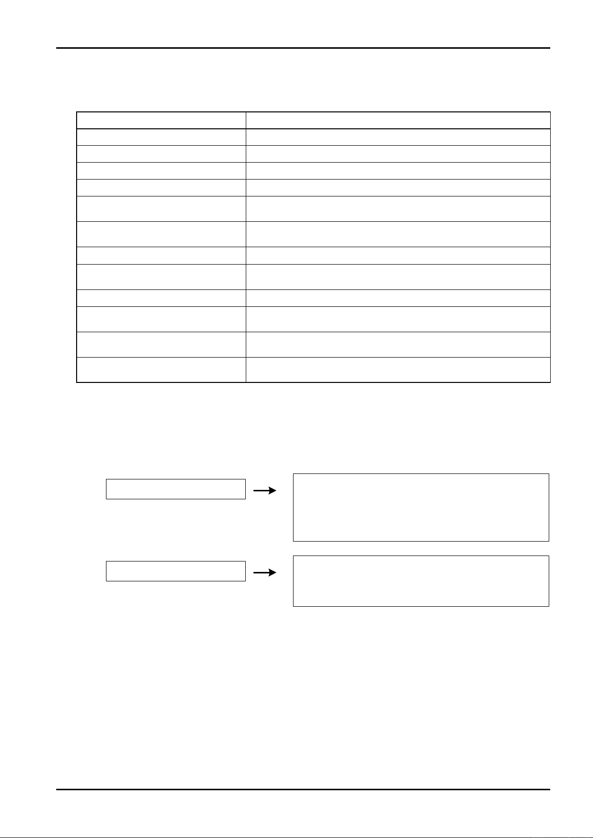
E-216-5N-E
Buzzer/alarmoutput
Batchprocessing
Electricpowerfailureoccurs
Operationistemporarilystopped
Totalflowvaluebeforeelectric
powerfailureismemorized
Aspowerfailureoccurs,
thepumpoutputisturnedOFF
withoutpumpdelaytimer
Powersupplyisrecovered
Pumpoperation
Batchprocessing
Pumpoperation
Temporarilystopped
Stopped
(4) Batch start unavailable conditions
If the conditions shown below are formed, the batch processing cannot be started even if pressing the START button.
Condition Response
Total display part does not display 0 Press RESET button to reset the total flow value to 0
END lamp lights up Press RESET button to turn OFF the END lamp
ALARM lamp lights up Press STOP or RESET button to reset the alarm
I.Lock lamp goes out Turn ON the interlock signal
External STOP input OFF
CH.No. display blinks
Batch setting quantity is 0 Set the batch setting quantity
Batch setting quantity ≦ forecasted
overrun quantity
Alarm buzzer is being ON After the buzzer is stopped by STOP button, reset the alarm
Batch setting quantity > batch setting
quantity upper limit setting value
Sleep mode is being ON
(dark or backlight is turned OFF)
All bits of SELECT.CH. are turned OFF
Turn ON the external STOP input (when the external operation is enabled by
parameter)
Check the batch setting quantity and touch the SET button. Indication of CH.No.
changes to lighting (when the external operation is enabled by parameter)
Set the batch setting quantity larger than forecasted overrun quantity
Change the value to the value that does not exceed the batch setting
quantity upper limit setting value
Reset the sleep mode
Turn ON any bit of SELECT.CH.
(when the external operation is enabled by parameter)
(5) Operation when electric power failure occurs
The operation when the power supply is blocked due to electric power failure during batch processing is shown below.
* When the electric power failure is recovered, "E8: electric power failure alarm" will be generated (refer to page 27).
(6) Upper limit of batch setting quantity
●
If you set the upper limit value by setting parameter, the setting of a value exceeding the upper limit
value as batch setting quantity can be disabled.
●
When setting the parameters C1 to CF, the value exceeding the parameter cannot be set.
●
If values exceeding the upper limit value have been set for C1 to CF, the operation cannot be started.
• After buzzer and alarm are reset, the restart is enabled by pressing START button.
To cancel it, press STOP + RESET buttons.
21
Page 22
E-216-5N-E
(7) External setting mode
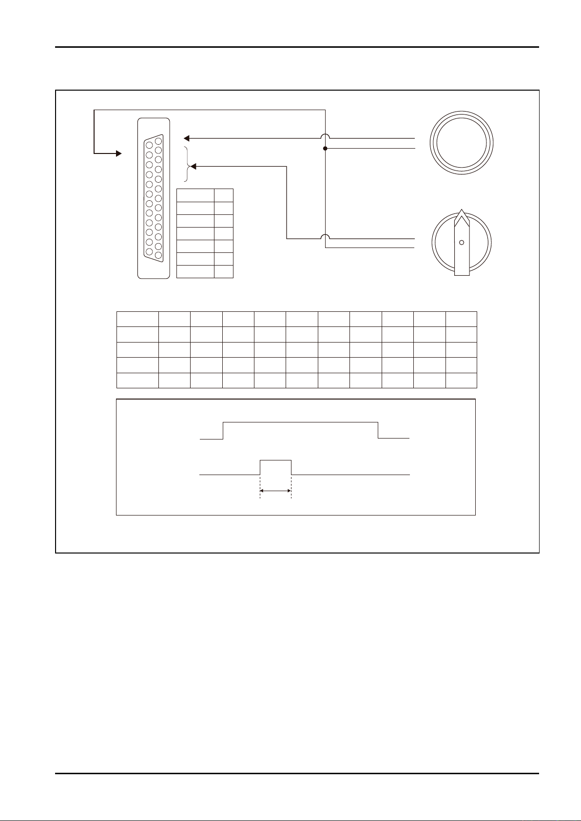
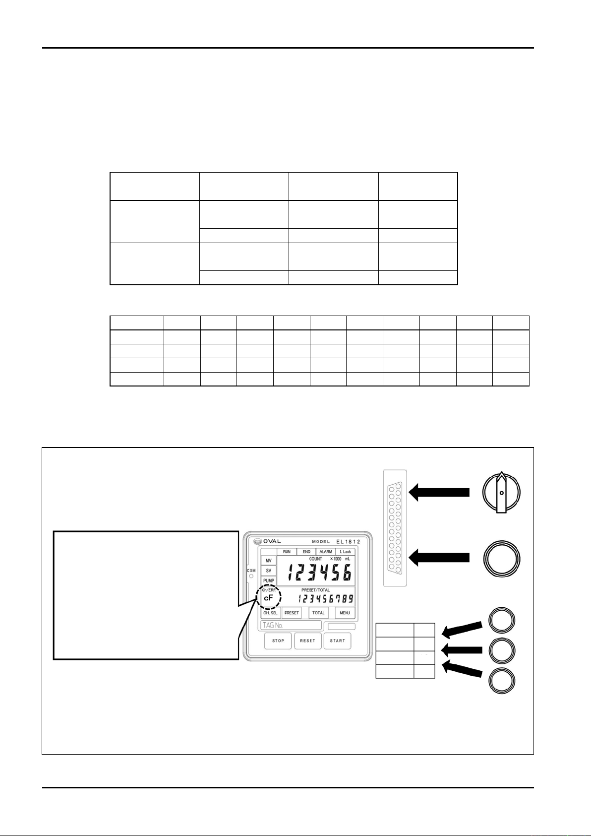
If the item 12 of parameter setting is set to 1, external channel selection and batch processing is enabled.(※1)
In case of external setting, the channel display C at display part CH./ERR will become lower case (example: c1).
Moreover, the channel selection on the front surface will be disabled. When you use the external operation input,
it is necessary to prepare the connector of D-SUB25 pin by yourself and connect the circuit for selecting channel
of external CH input to the D-SUB terminal on the rear surface of this device (refer to section 5.4 external
connection terminal).
Mode Function
External setting
mode (Remote)
START/STOP
RESET/SET
Button on front
surface
○ ○
External setting
CH. SELECT × ○
Front setting mode
(Front)
START/STOP
RESET/SET
○ ×
CH. SELECT ○ ×
Combination of SELECT and CH
CH.1 CH.2
CH.3 CH.4
CH.5
CH6 CH.7
CH.8 CH.9
SELECT 1 ON OFF ON OFF ON OFF ON OFF ON OFF
SELECT 2 OFF ON ON OFF OFF ON ON OFF OFF ON
SELECT 4 OFF OFF OFF ON ON ON ON OFF OFF OFF
SELECT 8 OFF OFF OFF OFF OFF OFF OFF ON ON ON
If the bit combination of external selector switch is other than above, "c0" is displayed at the display part and the
operation cannot be started.
Procedure for setting external setting mode
Each selection signal (contact a)
Held by ON or OFF
CH.F
①To use the external operation, set the parameter
No. 12 to "1: Remote" (refer to "9.1 Para meter
setting).
②The CH number selected by each selection signal
blinks (if it is blinking, the batch operation cannot
be started).
③The CH number lights up (xed) by inputting SET
signal (the batch operation can be started).
④Th e batch operation is implemented by external
STAR T, RESE T, a nd STOP signals (in a sam e
way as operation by buttons on front surface).
Fig.8.10 Procedure for setting external setting mode
22
SET signal (contact a)
One-shot signal
(200ms or more)
D-SUB connector
on rear surface
START
RESET
STOP
COM.1
Terminal block on rear surface
START signal(c ontact a)
RESET sig nal(co ntact a)
STOP signal(contact b)
One-s hot signal (2 00ms or mo re)
17
18
19
20
Selector switch
etc.
Push button
switch etc.
Push button
switch etc.
Page 23

E-216-5N-E
(8) Batch cancellation
If you want to cancel the batch operation in mid-flow, stop the operation temporarily, and then press "STOP" +
"RESET". At this time, the total display part will be reset to 0. If you press STOP + RESET while the pump is operated,
the operation will be stopped regardless of delay timer count value.
(9) Reset start function
Normally, the batch does not start without reset after the completion of batch, however, if the reset start function is
enabled by setting parameter, the batch start will be enabled without reset after the completion of batch. However,
while an alarm is generated, the batch does not start without resetting the alarm.
(10) Interlock function
If the external interlock signal is turned OFF, the operation cannot be started.
If the interlock signal is turned OFF during the batch operation, an alarm will be generated and the batch will be
temporarily stopped.
If the interlock signal is not used, short-circuit it with terminal block.
(11) Scaler function
If a pulse signal to be input is an unscaled pulse, the batch operation will be implemented by multiplying the
constant inherent to the flowmeter and converting it to integer industrial unit quantity.
(12) Accumulated counter value setting function
The accumulated counter value can be set to an arbitrary value within the range 0 to 999999 (can be set by
editing parameter).
If it is set to 0, it can be handled as zero reset. The value can be counted up to 999999999 (9 digits) on the
display.
23
Page 24
E-216-5N-E
CPU
(Pattern diagram)
1/1, 1/10, 1/100
In case of input
synchronization,
xed to 1/1
In case of input
synchronization,
unscaled pulse is
output
Flow rate
input
Scaler
0.00010 to 1.99999
standard 1.00000
1/1, 1/10, 1/100
Input dividing
Counter for
9-digit
totalization
Counter for
6-digit batch
Output
dividing
Waveform
forming
Pulse
output
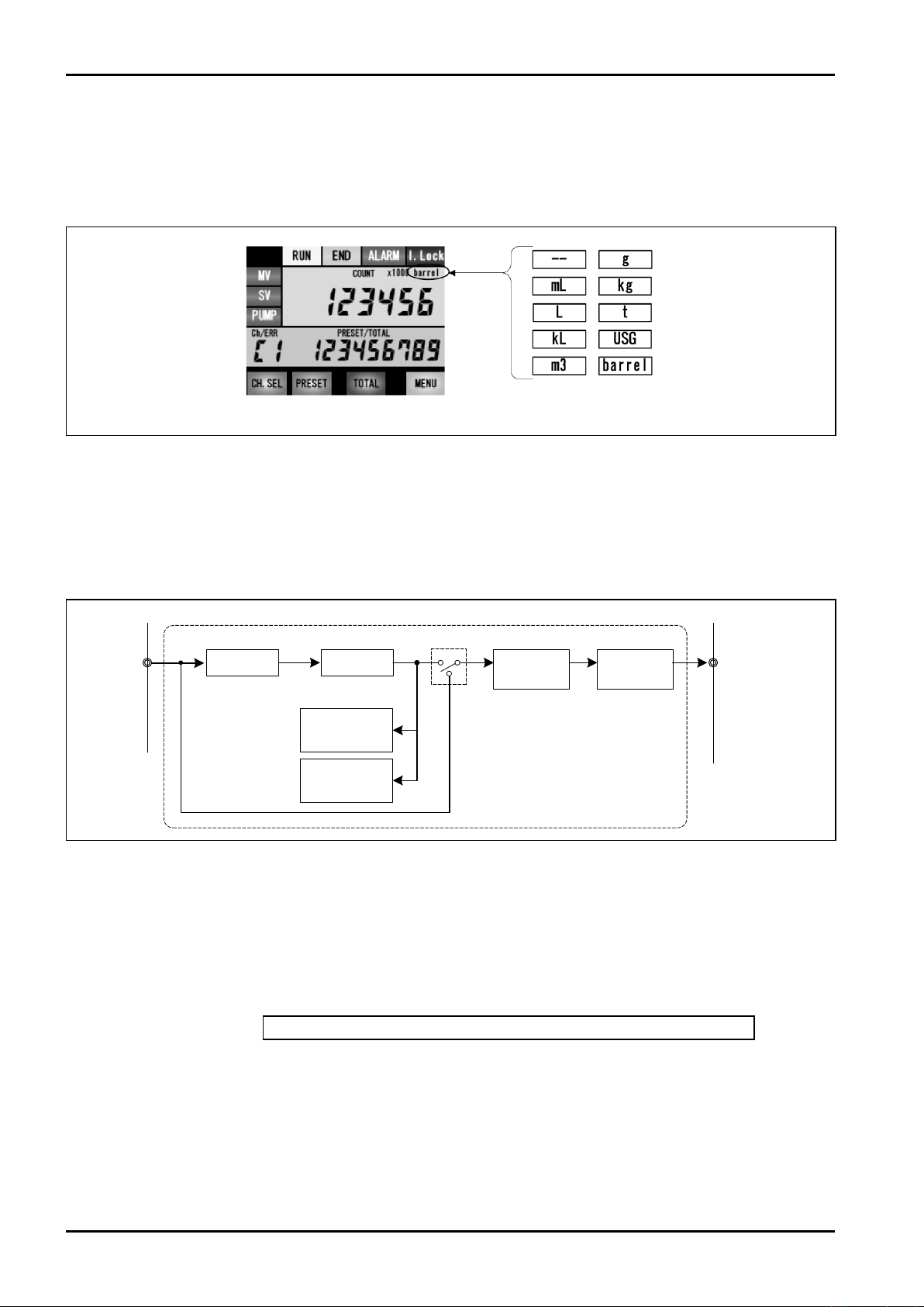
(13) Display of cumulative total flow unit
The cumulative total flow unit can be displayed in the upper right of total display part (parameter item 16).
The types of units to be displayed are shown below.
0: blank 1: mL 2: L 3: kL 4: m3 5: g 6: kg 7: t 8: USG 9: barrel
(The numbers are parameter setting numbers)
Fig. 8.11 Display position and type of cumulative total flow unit
(14) Dividing function
The dividing steps down the input pulse to one-tenth or one-hundredth. If the dividing is stepped down to one-
tenth, 1 is counted every 10 pulses. For the dividing, input dividing and output dividing are available. The input
dividing executes dividing before the pulse from flowmeter enters the counter. The output dividing divides the
external output pulse.
Scaler: If the flowmeter input pulse unit is unscaled, set it to correction pulse using a scaler.
Do the calculation with CPU.
Input dividing: Step down the input pulse to one-tenth or one-hundredth.
Thus, in case of one-tenth, for example, the counter counts 1 while the input pulse counts
10.
Do the calculation with CPU.
Arithmetic processing: As the calculation is processed by software of CPU, scaler / dividing function is realized
by calculation formula shown below.
Display counter = internal counter x scaler value x input dividing value
The fractional number after decimal point of calculation result should be cleared for each
batch for both of counter for batch and counter for integration.
For the output pulse multiply the output dividing value furthermore.
Input synchronization: Function for dividing only the counter value of batch counter and outputting the input
It is functioned by setting parameter of output dividing.
Parameter No.15 output dividing
3: 1/1syn…input synchronization (output dividing is fixed to 1/1)
24
unscaled pulse for the output pulse
Page 25
E-216-5N-E
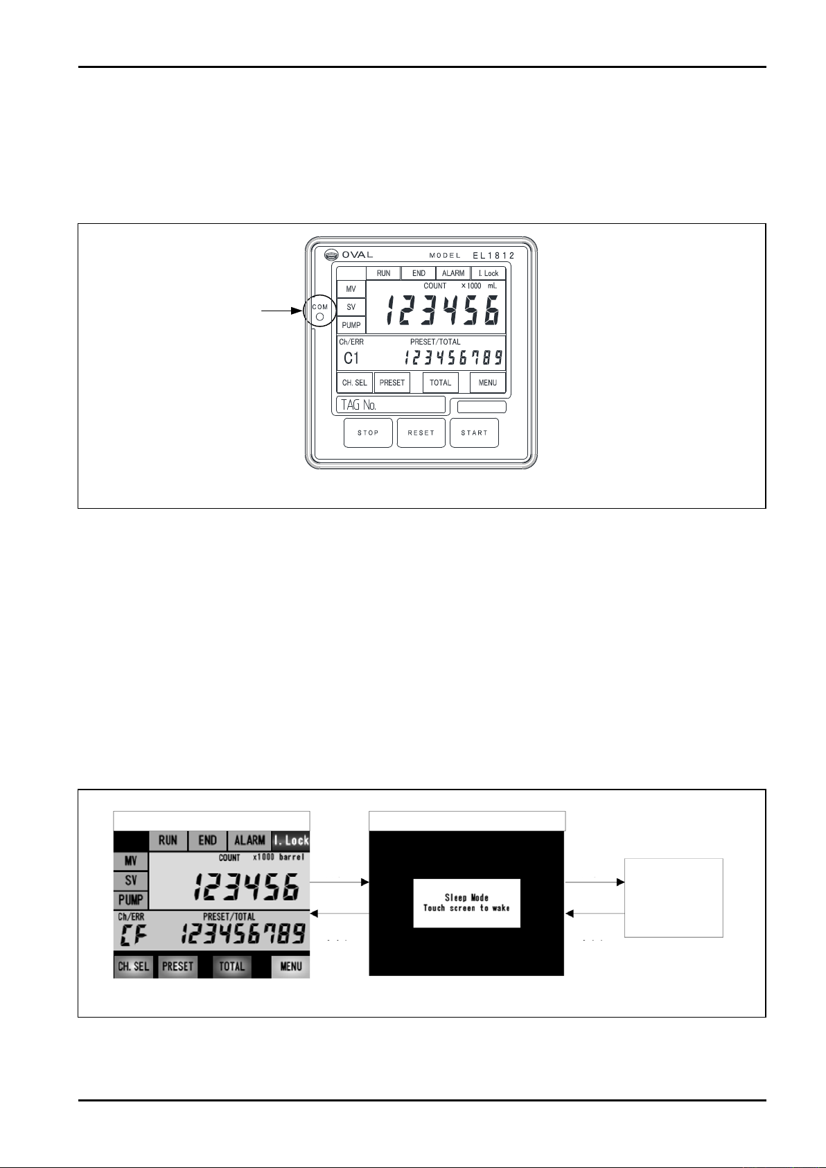
Normal status: blinking 1Hz
Abnormal status: blinking 4Hz
LCD module communication
monitoring part
LED blue name "COM"
(15) Function for monitoring communications with LCD module
This device can monitor the communication status of CPU and LCD module with LED on the front surface.
・Normal status: LED blinks 1Hz
・Abnormal status: LED blinks 4Hz (screen switching freezes, for example)
* If an error is generated again after turning ON/OFF the power supply, the LCD may be broken.
Please contact the service department of our company.
Fig. 8.12 LCD module communication monitoring part
(16) Sleep function
To protect the backlight of display module, the sleep function is mounted. Set the sleep function by turning ON/
OFF the sleep mode.
・ON: If the touch panel is not operated in case of other than during batch processing for one minute
continuously, the sleep mode will be displayed on the LCD module.
If five minutes pass furthermore, the backlight of LCD module will be turned OFF.
To cancel the sleep mode, touch the LCD module.
First touching of LCD module: backlight will be turned ON
Second touching of LCD module: sleep mode display will be cancelled
* If leak error is generated while the sleep mode is displayed or the backlight is turned OFF, the screen will
be automatically restored to the bright display.
* While the sleep mode is displayed or the backlight is turned OFF, the batch cannot be started.
・OFF: The screen is always displayed while the power is distributed.
Example) [BATCH PROCESSING] screen
No
operation
1 minute
passes
Touch the
display
[In sleep mode] displayed screen
No
operation
5 minutes
passes
LCD module
backlight is turned
OFF
Touch the
display
Fig. 8.13 Sleep function
25
Page 26
E-216-5N-E
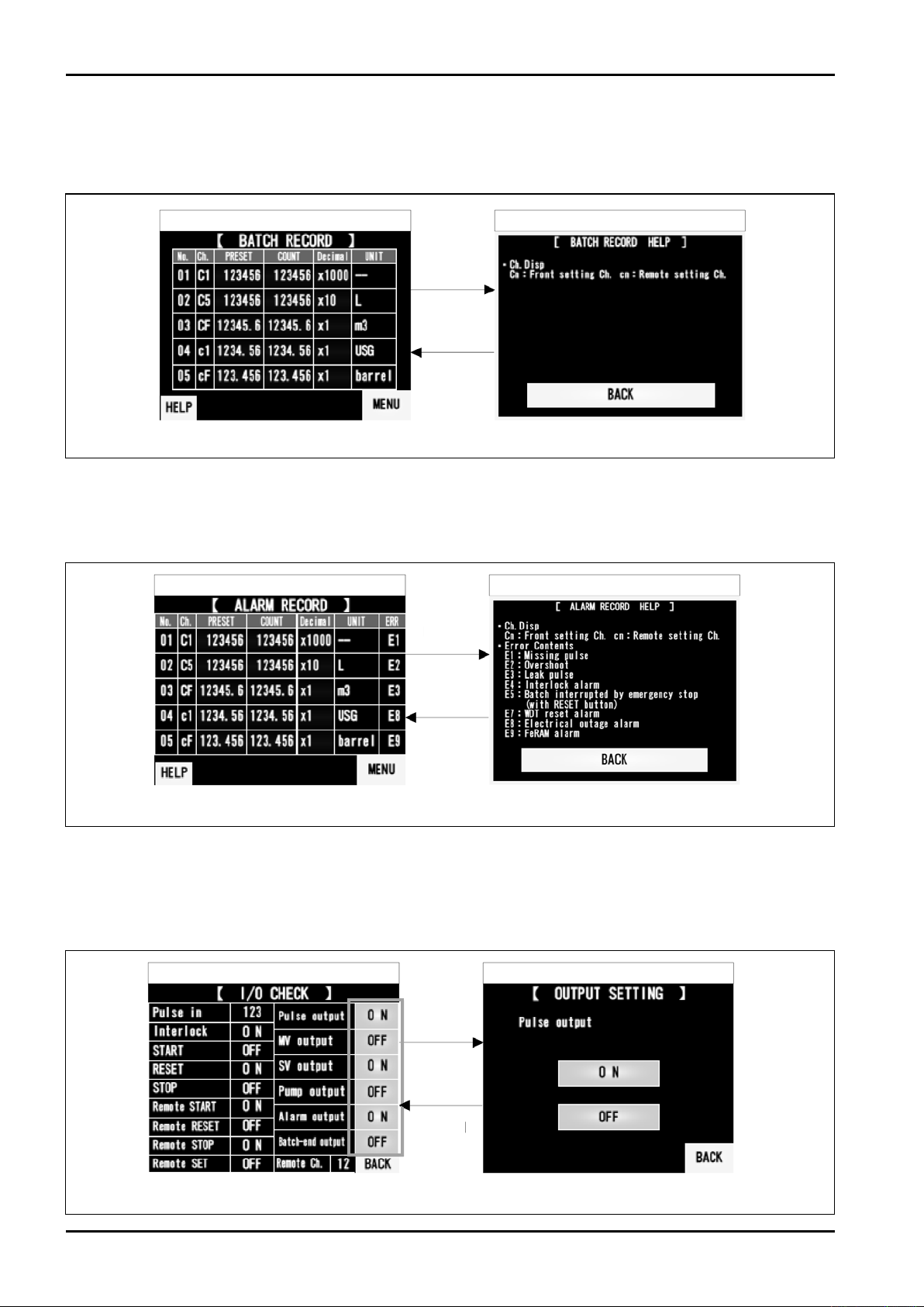
(17) Batch history function
You can check the history of recent five batches (expanded from MENU screen). The supplement of content on
the screen is displayed on HELP screen.
[BATCH RECODE] screen [BATCH RECODE HELP] screen
"HELP"
"BACK"
Fig. 8.14 Batch history function
(18) Alarm history function
You can check the history of recent five alarms (expanded from MENU screen). The supplement of content on
the screen is displayed on HELP screen.
[ALARM RECODE] screen
"HELP"
"BACK"
Fig. 8.15 Alarm history function
[ALARM RECODE HELP] screen
(19) I/O confirmation function
You can check the status of I/O signal related to batch processing (expanded from SYSTEM screen). The output
signal can be arbitrarily turned ON/OFF by touching each field. When returning to MENU screen, all output
signals will be turned OFF. * This is the function prepared for maintenance.
[I/O CHECK] screen
"Each button"
Example) [OUTPUT SETTING] screen
26
"BACK"
Fig. 8.16 I/O confirmation function
Page 27
E-216-5N-E
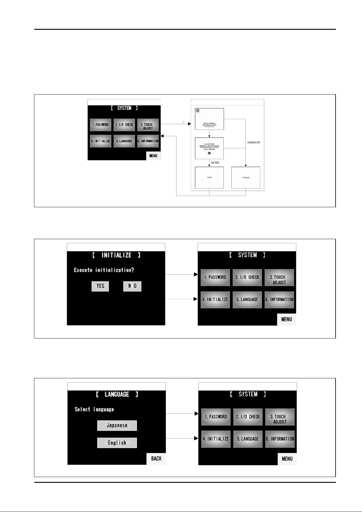
(20) Touch panel adjustment function
Correct the sensitivity using the correction function of LCD module itself (expanded from SYSTEM screen).
Carry out the operation following the instructions on the screen (touch the red circles in sequence).
If "SAVED" screen is displayed finally, the correction is completed. The screen will automatically return to SYSTEM screen.
If the correction is not completed within 15 seconds, "CANCELED" screen will be displayed and the screen will automatically
return to SYSTEM screen.
[SYSTEM] screen
"3.TOUCH
ADJUST"
Fig. 8.17 Touch panel adjustment function
[TOUCH ADJUST] screen
(21) Initialization function
Parameters and accumulated total flow value etc. can be initialized (expanded from SYSTEM screen).
* Standard values are set for parameters.
[INITIALIZE] screen [SYSTEM] screen
"YES"
(Initialization)
"NO"
(Cancel)
Fig. 8.18 Initialization function
(22) Language selection function
The language displayed on the touch panel can be selected from English and Japanese (expanded from
SYSTEM screen).
* Standard display language is English.
[LANGUAGE] screen Example) [SYSTEM] screen Japanese
"Japanese"
or
"English"
"BACK"
(Cancel)
Fig. 8.19 Language selection function
27
Page 28
E-216-5N-E
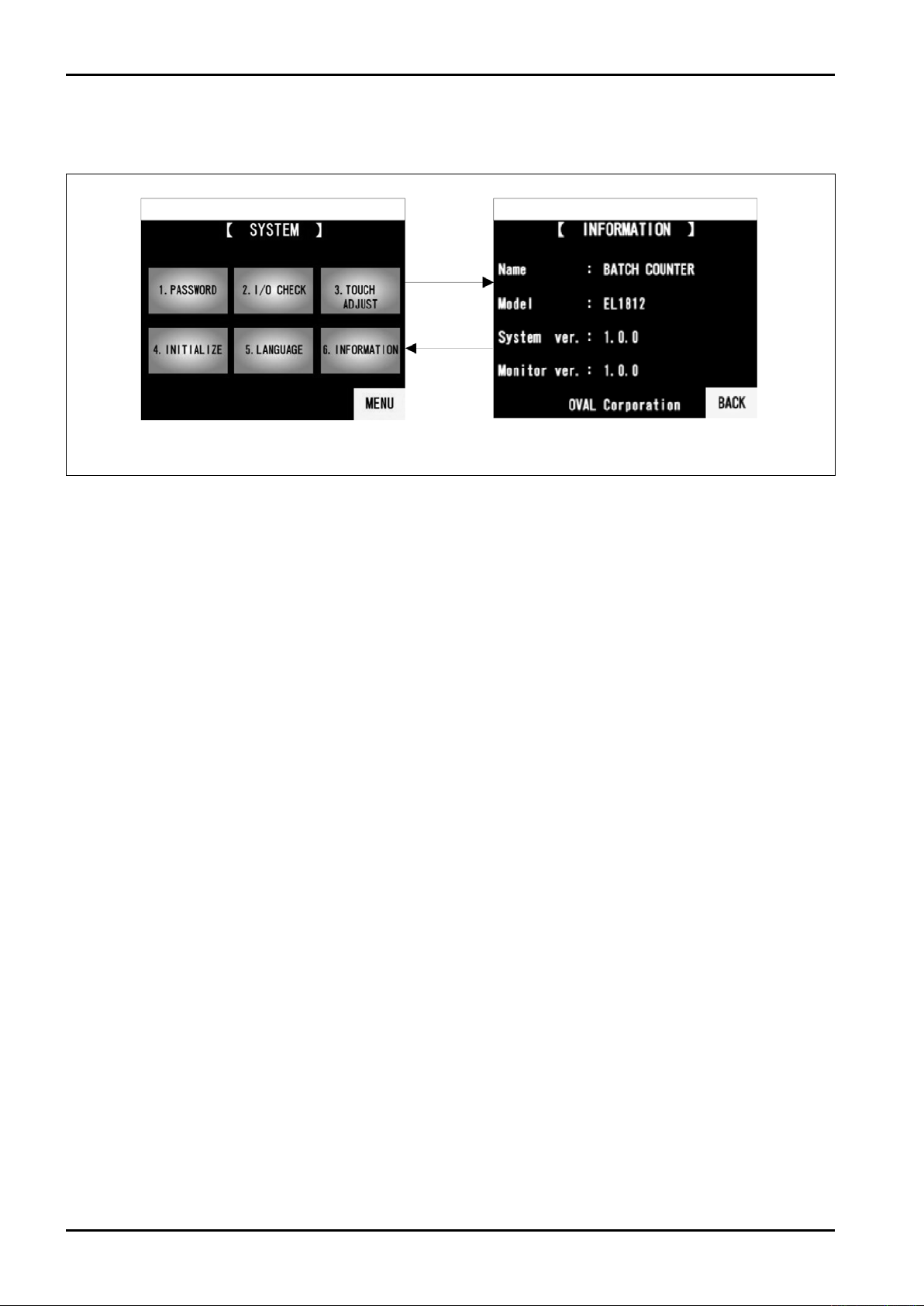
(23) Product information
Model and system version are displayed (expanded from SYSTEM screen).
[SYSTEM] screen
[INFORMATION] screen
"6.INFOR
MATION"
"BACK"
Fig. 8.20 Product information
28
Page 29
E-216-5N-E
Batchprocessing:temporarilystopped
SV/MVoutput:OFF
PUMPoutput:turnedOFFaftertimer
AlarmisresetbyturningONtheSTOPbutton
afterthebuzzeristurnedOFF
Signal
Buzzer:ON
ALARMlamp/output:ON
Reset
STOPbutton
PressSTOPbuttonafterthebuzzeristurnedOFF
Pulsenon-receiptisgenerated
PressRESETbuttonafter
thebuzzeristurnedOFF
Atthesametimeasresetof
alarm,thetotalflowvalueisreset.
PressRESETbuttonafter
thebuzzeristurnedOFF
Atthesametimeasresetof
alarm,thetotalflowvalueisreset.
Overrunalarm
Leakalarm
Totalflow≧leakerrorsettingvalue
Totalflow≧batchsettingquantity
+Forecastedoverrunquantity
Signal Reset
Buzzer:ON
Thebatchoperationiscompleted(END)
PUMPoutput:turnedOFFafterdelaytimer
PUMPoutput:turnedOFFafterdelaytimer
ALARMlamp/output:ON
STOPbutton
Signal Reset
Buzzer:ON
ALARMlamp/output:ON
STOPbutton
AlarmisresetbyturningONinterlocksignaland
STOPbuttonafterthebuzzeristurnedOFF
Batchprocessing:temporarilystopped
SV/MVoutput:OFF
PUMPoutput :turnedOFFafterdelaytimer
PressRESETbuttonafter
thebuzzeristurnedOFF
Atthesametimeasresetof
alarm,thetotalflowvalueisreset.
PressRESETbuttonafter
thebuzzeristurnedOFF
Atthesametimeasresetof
alarm,thetotalflowvalueisreset.
AfterthebuzzeristurnedOFF
InterlocksignalisturnedON
STOPbutton
Overrunalarm
Leakalarm
Interlockalarm
Totalflow≧leakerrorsettingvalue
Totalflow≧batchsettingquantity
+Forecastedoverrunquantity
Signal Reset
Buzzer:ON
Thebatchoperationiscompleted(END)
PUMPoutput:turnedOFFafterdelaytimer
PUMPoutput:turnedOFFafterdelaytimer
ALARMlamp/output:ON
STOPbutton
Signal Reset
Buzzer:ON
ALARMlamp/output:ON
STOPbutton
Signal Reset
Buzzer:ON
ALARMlamp/output:ON
STOPbutton
PressRESETbuttonafter
thebuzzeristurnedOFF
Atthesametimeasresetof
alarm,thetotalflowvalueisreset.
Overrunalarm
Totalflow≧batchsettingquantity
+Forecastedoverrunquantity
Signal Reset
Buzzer:ON
Thebatchoperationiscompleted(END)
PUMPoutput:turnedOFFafterdelaytimer
ALARMlamp/output:ON
STOPbutton
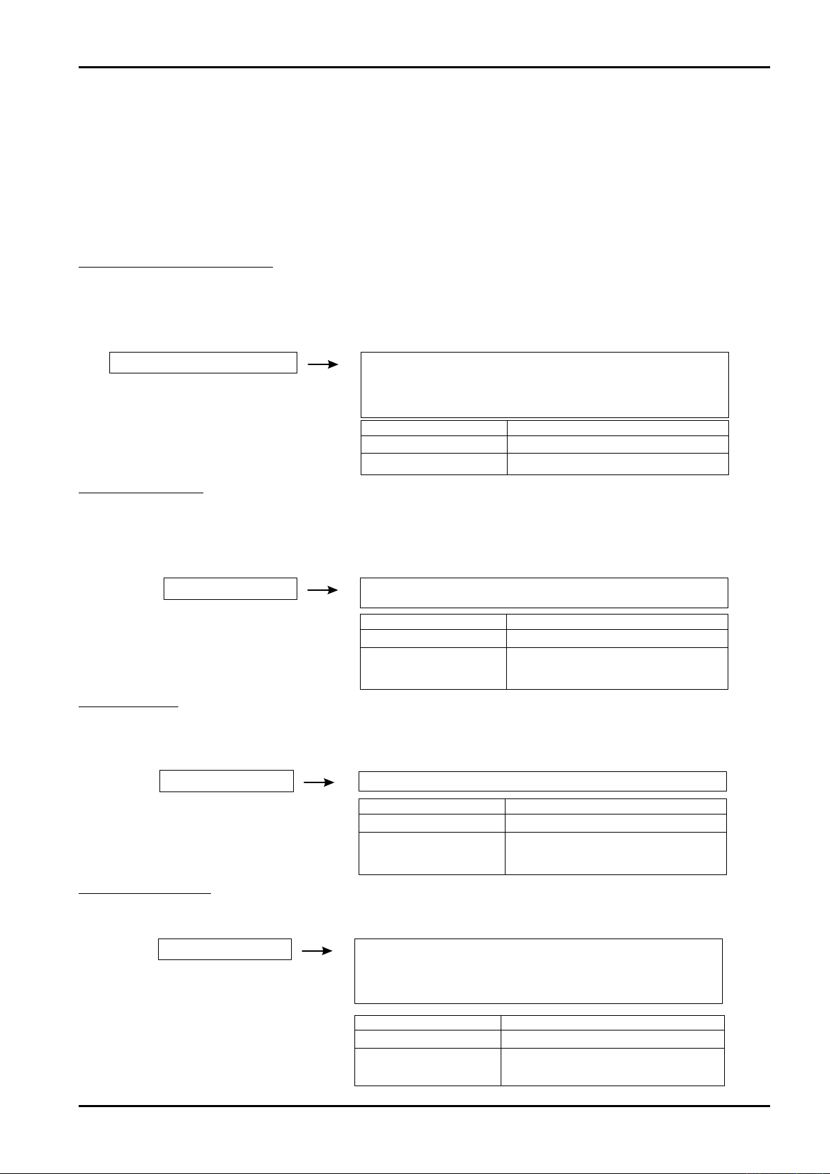
8.6 Alarm processing
There are eight types of alarms shown below.
E1: pulse non-receipt alarm E2: overrun alarm E3: leak alarm E4: interlock alarm
E5: emergency stop by RESET button E7: WDT reset alarm E8: electric power failure alarm E9: FeRAM alarm
Buzzer sounds until STOP button is turned ON or during the setting time after the alarm is generated.
The buzzer can be continuously sounded until the alarm is reset by setting parameter.
While overrun / leak alarm is being generated, the batch cannot be started.
E1: pulse non-receipt alarm
The pulse non-receipt alarm is generated if a pulse is not input for a setting time (non-receipt pulse interval time)
until the total flow value reaches the batch setting quantity after the batch processing is started.
However, the alarm is not monitored for five seconds after the start.
If the value is set to 0, the alarm is not monitored.
E2: overrun alarm
This alarm is generated if the total flow is "batch setting quantity + overrun quantity" or more.
From the point where the total flow value is same as batch setting quantity to the point after the completion time
is set to be a monitoring zone.
If the value is set to 0, the alarm is not monitored.
E3: leak alarm
This alarm is generated if a pulse exceeding the setting quantity (leak error setting value) is input until the batch
is started after the previous batch is completed (END).
If the value is set to 0, the alarm is not monitored.
E4: interlock alarm
This alarm is generated if the interlock signal is turned OFF from the point where the batch is started to the point
where the batch setting quantity is same as total flow value.
29
Page 30
E-216-5N-E
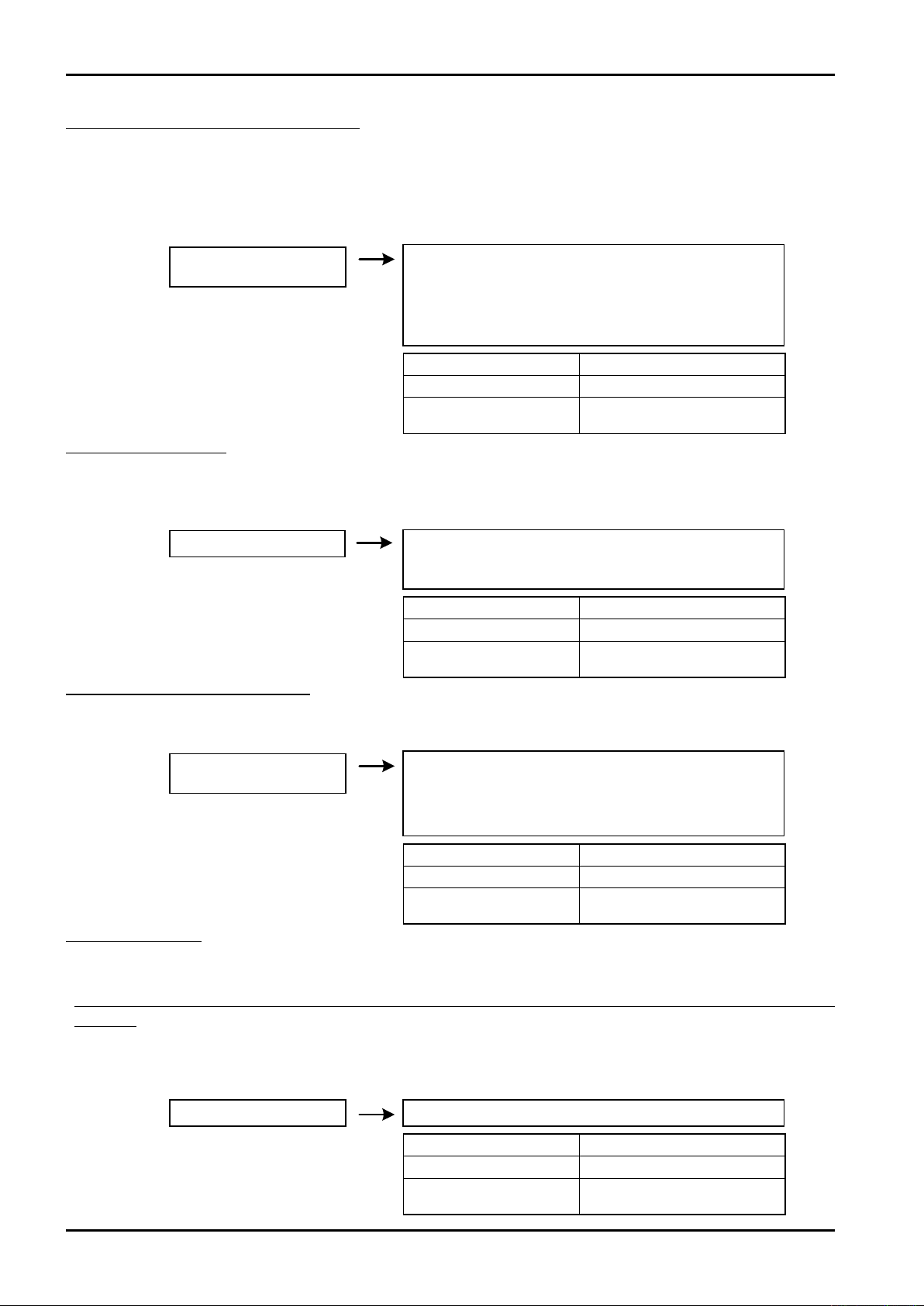
E5: emergency stop by RESET button
This alarm is generated when the temporary stop of batch processing is executed by pressing RESET button
instead of STOP button.
* Even if the STOP malfunctions the operation can be stopped, however, this is an alarm that indicates that
restart is disabled while the STOP is not functioning.
If the STOP may not be functioning normally, please contact the service department of our company.
Emergency stop by
RESET button
Batch processing: temporarily stopped
SV/MV output: OFF
PUMP output: turned OFF after delay timer
The operation is restarted by turning ON the START button
after buzzer / alarm is turned OFF
Signal Reset
Buzzer: ON STOP button
ALARM lamp / output: ON
Press STOP button after the
buzzer is turned OFF
E7: WDT reset alarm
This alarm is generated by CPU is reset by watchdog timer IC.
*
This is an alarm generated when a clock signal of CPU is not input in the watchdog timer IC for a constant time.
If this error is generated again, the internal board may be broken. Please contact the service department of our company.
WDT reset alarm
Batch processing: batch is cancelled (batch quantity is notleft)
SV/MV output: OFF
PUMP output: OFF
Signal Reset
Buzzer: ON STOP button
ALARM lamp / output: ON
Press RESET button after the
buzzer is turned OFF
E8: electric power failure alarm
This alarm is generated when the power supply is turned OFF during batch processing.
This error is not generated by power OFF in case of other than during batch processing.
Electric power failure
alarm
Batch processing: temporarily stopped
SV/MV output: OFF
PUMP output: OFF
Operation is restarted by turning OFF buzzer / alarm
Signal Reset
Buzzer: ON STOP button
ALARM lamp / output: ON
Press STOP button after the
buzzer is turned OFF
E9: FeRAM alarm
The parameter information and the batch processing information are written/read into/from FeRAM when the data is
changed or the power supply is ON/OFF. If check error is generated in CPU at writing/reading, an alarm will be generated.
* The information that generates reading check error at power ON (parameter or batch processing, or both of them) will be
initialized.
* If FeRAM alarm is generated, FeRAM may be expiring. Please contact the service department of our company.
* Wait for "10 seconds or more" until turning ON the power supply again after power OFF of batch counter main unit.
If the time between power OFF and ON is extremely short, writing/reading in/from FeRAM may not be implemented
normally.
FeRAM alarm
Batch processing: standby status
Signal Reset
Buzzer: ON STOP button
ALARM lamp / output: ON
Press RESET button after the
buzzer is turned OFF
30
Page 31
9. CHANGE OF SETTING VALUE
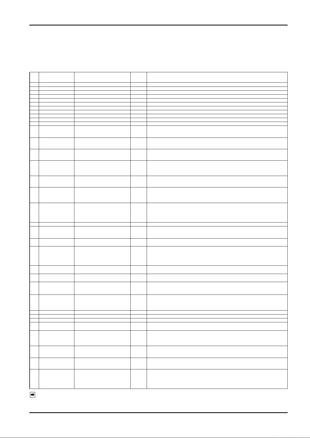
9.1 Parameter setting
The parameters can be set on [PARAMETER] screen.
However, if a password is set, the screen will be expanded after the password is certified.
No. Item Range
C1
Channel 1
C2
Channel 2
C3
Channel 3
C4
Channel 4
C5
Channel 5
C6
Channel 6
C7
Channel 7
C8
Channel 8
C9
Channel 9
CF
Cannel free
02
Scaler value
03
Initial setting value
Terminal setting
04
value
Overrun forecast
05
value
06
Overrun volume
Leak failure
07
setting value
Non-arrival pulse
08
interval time
Completion
09
monitoring
setting value
0A
Accumulation counter
Pump output
0B
delay timer
Buzzer ON time
0C
setting
Batch setting
0D
volume upper limit
setting value
Reset start
0E
function
0F
Measure unit
Accumulated
11
display time
Operation switch
12
selection
13
Pulse output width
14
Input division
15
Output division
16
Integration unit
17
Sleep mode
20
Language
21
Password
H1
System Ver.
0 to 999999 count 0
0 to 999999 count 0
0 to 999999 count 0
0 to 999999 count 0
0 to 999999 count 0
0 to 999999 count 0
0 to 999999 count 0
0 to 999999 count 0
0 to 999999 count 0
0 to 999999 count 0
0 to 999999 count 1
0 to 9999 count 80
0 to 9999 count 80
0 to 99 count 2
0 to 99 count 2
0 to 99 count 10
0 to 999sec 5
0 to 99sec 5
0 to 999999 0
0 to 9999sec 30
0 to 999sec 0
0 to 999999 count
0: without, 1: with 0
0:× 1000 1: ×100 2: ×10 3: ×1
4: × 0.1 5: × 0.01 6: × 0.001
0 to 9sec 0
0: Front (front surface
setting mode
1: Remote (external setting
mode)
0: 150μsec 1: 1msec 2: 50msec
0: 1/1 1: 1/10 2: 1/100
0: 1/1 1: 1/10 2: 1/100 3: 1/1syn
0: --(blank) 1: mL 2: L 3: kL
4: m3 5: g 6: kg 7: t 8: USG 9: barrel
0: OFF 1: ON
0: Japanese 1: English
Standard
value
999999
3
0
1
0
0
0
1
1
111111
Remark
Sets the batch setting volume of channel 1 [C1].
Sets the batch setting volume of channel 2 [C2].
Sets the batch setting volume of channel 3 [C3].
Sets the batch setting volume of channel 4 [C4].
Sets the batch setting volume of channel 5 [C5].
Sets the batch setting volume of channel 6 [C6].
Sets the batch setting volume of channel 7 [C7].
Sets the batch setting volume of channel 8 [C8].
Sets the batch setting volume of channel 9 [C9].
Sets the batch setting volume of channel free [CF].
Sets the coefcient value to be used for obtaining the integrated ow rate.
Sets the timing for opening MV (large valve).
If it is set to initial setting value [80] and the batch setting volume is set to
[1000], the MV opens when the integrated value reaches 80.
Sets the timing for closing MV (large valve).
If it is set to initial setting value [80] and the batch setting volume is set to
[1000], the MV closes when the integrated value reaches 920.
Sets the timing for closing SV (small valve).
If the overrun forecast value reaches is set to [2] and the batch setting volume is set
to [1000], the SV closes when the integrated value reaches 998.
Sets the timing for generating overrun alarm.
If the batch setting volume is set to [1000] and the overrun volume is set to [2],
<E2> ala rm is gen erated when the integr ate d value reac hes 100 2 within the
completion monitoring time.
Sets the time for generating leak alarm.
If the leak failure setting volume is set to [10], <E3> alarm is generated when 10
count up between completion and start of batch operation.
Sets the timing for generating pulse non-arrival alarm. It is also possible to
disable the monitoring of non-arrival of pulse by setting it to 0 second. If the
non-arrival pulse interval time is set to [5], <E1> alarm is generated when the
non-arrival time of pulse reaches 5 seconds.
The completion monitoring time is set for monitoring the overrun alarm after
the batch volume integrated value reaches the setting value.
The completion monitoring time is counted after the batch volume integrated
value becomes same as batch setting volume. The batch becomes END after
the time set by parameter is over.
Sets the accumulated tota l value up to 6 d igits. Up to 9 digi ts can be c ounted o n the display.
Sets the time for continuing the pump output after SV is closed.
If the pump output delay timer is set to [30], the pump output is turned OFF in
30 seconds after the import is completed.
Sets the time in which alarm buzzer is turned ON.
0: continued 1 to 999: sounds within the setting time (1 to 999 seconds)
Disables the setting of batch volume e xceedi ng the batch setting volume
upper limit setting value by parameter setting.
When you set the paramet er C1 to CF, a value exceeding the upper l imit
value cannot be set. If a value more than upper limit value is set for C1 to CF
preliminarily, the operation cannot be started.
Enables or disables the reset start function.
[0] Disabled, [1] Enabled
Sets the unit coefcient.
[0] 1000, [1] 100, [2] 10, [3] 1, [4] 1/10, [5] 1/100, [6] 1/1000
Sets the time in which accumulated total value is displayed when TOTAL button is input.
0: Accum ulated tot al value is displaye d while TOTAL button is input 1 to 9:
Automatically reset to preset value display after the setting time is over
Selects the setting method of switch operation.
[0] Front surface setting mode
[1] External setting mode
Sets the pulse width of output pulse.
Sets the input division by software.
Sets the division of output pulse.
Sets the integration unit of display.
Enables or disables the sleep mode for protecting backlight.
0: always displayed while the power is distributed
1: mode s hifts to sleep mode if nothin g is operated for 1 min ute or
more during other than batch operation
Sets the display language.
※ This item is not displayed on PARAMETER screen. The language is
switched from SYSTEM screen.
Sets the password.
※ This item is not displayed on PARAMETER screen. The password is
switched from SYSTEM screen.
You can check the system version.
The sys tem ve rsi on may be changed witho ut notice depen din g on the
product.
※
This item is not displayed on PARAMETER screen. You can check
the version from SYSTEM screen.
E-216-5N-E
NOTE:
The batch setting volumes C1 to C9 can be set only in the parameter setting menu.
The batch setting volume CF (free) can be set from batch processing screen at the usual operation.
In case of 0, you can’t start filling operation.
31
Page 32
E-216-5N-E
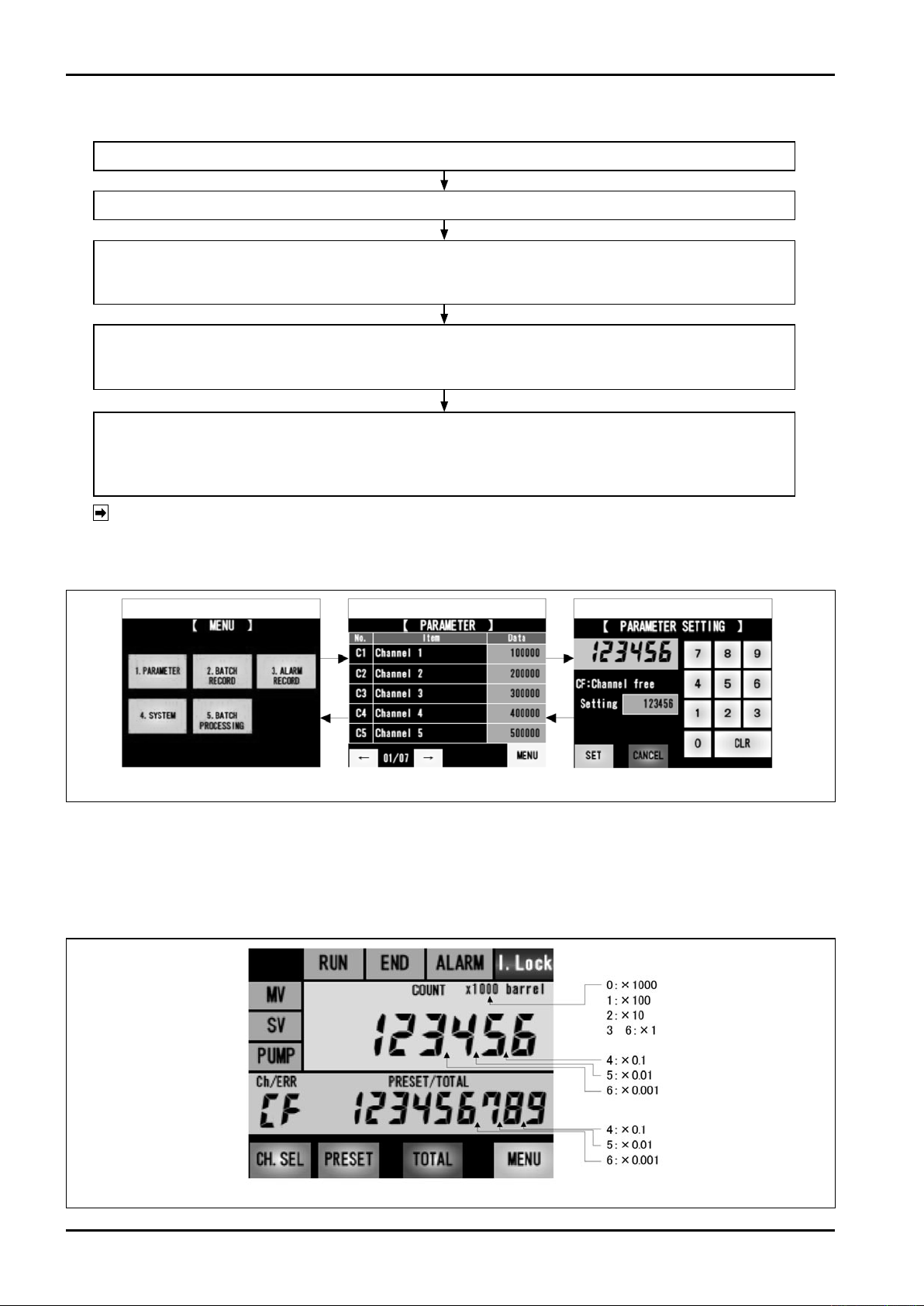
How to set a parameter
Touch "1.PARAMETER" on [MENU] screen to shift to [PARAMETER] screen.
Display the parameters for five items each from C1 on the touch panel.
Shift to the next parameter screen by pressing → button and shift to the previous parameter screen by pressing
← button.
Select the data field of a parameter to be changed and change the setting using a numeric keypad and CLR button.
If you touch SET button, the changed parameter will be memorized and the screen will return to the parameter screen.
The changed data will be reflected to the data field of the changed item.
If you touch CANCEL button, the change will be cancelled and the screen will return to the parameter screen.
If the change of a parameter you want to change is terminated, touch MENU button.
Quit [PARAMETER] screen and shift to [MENU] screen.
The changed data will be memorized until the next change.
Then, touch "5. BATCH PROCESSING" button and return to the measurement screen.
NOTE:
● The item loops among parameters C1 to 17 (sleep mode).
● In the following status, the screen cannot shift to PARAMETER screen.
・During batch processing (RUN lamp is lighting/blinking)
・While the pump is operated (PUMP lamp is lighting) ・During completion (END lamp is lighting)
[MENU] screen
[PARAMETER] screen [PARAMETER SETTING] screen
Fig. 9.1 How to set a parameter
* : For the measurement unit, select a display method (it is the selection only for display and it is not related
to internal calculation).
0: display x1000 1: display x100 2: display x10 3: display x1
4: display x1, decimal point is at the last digit of total flow value / preset value
5: display x1, decimal point is at second last digit of total flow value / preset value
6: display x1, decimal point is at third last digit of total flow value / preset value
32
to
Fig. 9.2 Measurement unit
Page 33
Password function
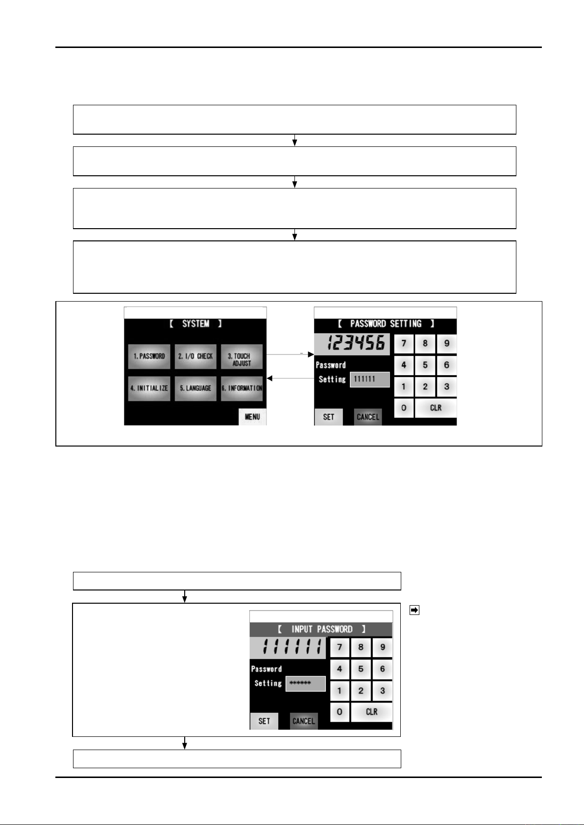
● Setting of password (at initial setting)
Touch "4.SYSTEM" on [MENU] screen to shift to [SYSTEM] screen.
Next, touch "1.PASSWORD".
[INPUT PASSWORD] screen will be displayed. Input "111111 (default)".
After the password is input, touch SET button to shift to [PASSWORD SETTING] screen.
Change the password using a numeric keypad and CLR button.
・Max. 6-digit arbitrary number can be set.
* It is also possible to delete the password by clearing the number and touch SET button.
If you touch SET button twice within one second, the changed password will be memorized and the screen
will return to [SYSTEM] screen. If you touch CANCEL button, the change will be cancelled and the screen
will return to [SYSTEM] screen.
Then, touch "MENU" and "5. BATCH PROCESSING" buttons and return to the measurement screen.
E-216-5N-E
[SYSTEM] screen
"1.PASS
WORD"
"SET"
"CANCEL"
Fig. 9.3 How to set a password
[PASSWORD SETTING] screen
● Timing when the input of password is required
If a password is set, the input of password is required in the timings (1) to (5) shown below. For the current
value of password, "* (asterisk)" is displayed for the number of setting digit.
(1) When you touch each data field on [PARAMETER] screen (when you want to change a parameter)
If you input the password once, re-input of password will not be required until quitting [PARAMETER] screen.
⇒
(2) When you touch "1.PASSWORD" (when you want to change the password)
(3) When you touch "2.IN/OUT.CHECK"
(4) When you touch "3.TOUCH.ADJUST"
(5) When you touch "4.INITIALIZE"
In the cases (1) to (5) shown above
[INPUT PASSWORD] screen
[INPUT PASSWORD] screen shown right
is displayed.
Carry o ut the setting using a nu meric
keypad and CLR button. If you touch SET
button, the password will be set. If you
touch CANCEL button, the password will
be cancelled.
If the password is correct, the screen will shift to each screen.
NOTE:
If a password is set, make a note
not to forget it.
If yo u fo r ge t th e pa s s wo r d,
please contact business office or
service center of our company.
33
Page 34
E-216-5N-E
-
0
1
2
3
4
5
1 -1
1- 2
2 -1
3 -1
4 -1 -1
5 -1
5 -2
5 -3
-
4 -1 -2
4 -1- 3
4 -2 -1
4 -2 -2
4 -2 -3
4 -3 -1
4 -3 -2
4 -3 -3
4 -4 -1
4 -4 -2
4 -4 -3
4 -6 -1
4 -6 -2
* Only when the password is set
* Only when the password is set
* Only when the password is set
* Only when the password is set
2 -2
3 -2
4 -5 -1
4 -5 -2
4 -5 -3
* Only when the password is set
4 -2 -4
5
5 -1
5 -2
5 -3
-
6
-
Startup screen
Top screen
5. BATCH PROCESSING
*After the top screen, the screen automatically shifts to BATCH PROCESSING screen
BATCH PROCESSING screen
[CHANNEL SELECT]
[PRESET SETTING]
[MENU]
1. PARAMETER
[PARAMETER]
[PARAMETER SETTING]
2. BATCH RECORD
■Sleep mode screen system
[BATCH RECORD]
[BATCH RECORD HELP]
3. ALARM RECORD
[ALARM RECORD]
[ALARM RECORD HELP]
4. SYSTEM
1. PASSWORD
[INPUT PASSWORD]
[PASSWORD SETTING]
2.I/O CHECK
[INPUT PASSWORD]
[I/O CHECK]
[OUTPUT SETTING]
3. TOUCH ADJUST
[INPUT PASSWORD]
[TOUCH ADJUST]
4. INITIALIZE
[INPUT PASSWORD]
[INITIALIZE]
5. LANGUAGE
[INPUT PASSWORD]
[LANGUAGE]
6. INFORMATION
[INFORMATION]
5. BATCH PROCESSING
BATCH PROCESSING screen
[CHANNEL SELECT]
[PRESET SETTING]
* P ar amete r No.17
Vali d only whe n the s lee p mo de is set
to "1: ON"
Each screen
[Sleep mode] display screen
Backlight OFF
Screen system
34
Page 35
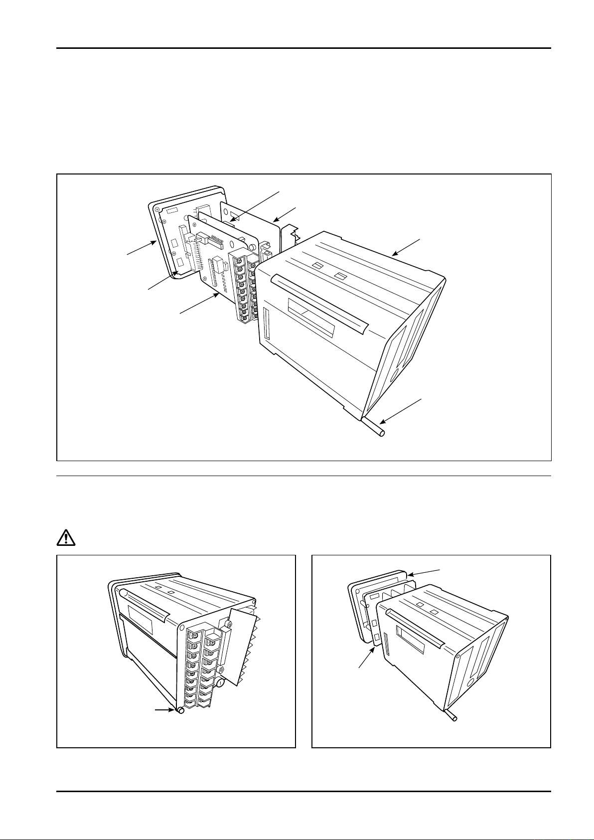
E-216-5N-E
9.2 Configuration of internal device
This device has internal devices; "display unit", "power supply board", "input board", and "output board" as
shown in Fig. 9.4.
The display unit is configured with LCD module and CPU board. Power supply and input board are configured by
connector connection.
Input board and output board are connected to CPU board with each connector.
Input board and output board have terminal block connected to external.
Power supply board
Output board
Enclosure
Display unit
LCD module /
CPU board
Input board
Front frame/enclosure
installation screw
(x4)
Fig. 9.4 Configuration of internal devices
9.3 Removal of inner assembly
The internal board is removed by disconnecting this assembly from the installation panel.
CAUTION:
Front frame/enclosure
installation screw
Do not fail to remove the inner asseembiy after turning OFF the power supply to this device.
Pull out LCD
module/CPU
board, and a set of
internal devices
(x4)
Fig.9.5 Fig.9.6
Remove the front frame
(1) Unscrew four continuous-thread studs on rear
surface of main unit.
(2)
Remove the front frame and pull out display unit, power
supply/input board, and output board collectively.
35
Page 36
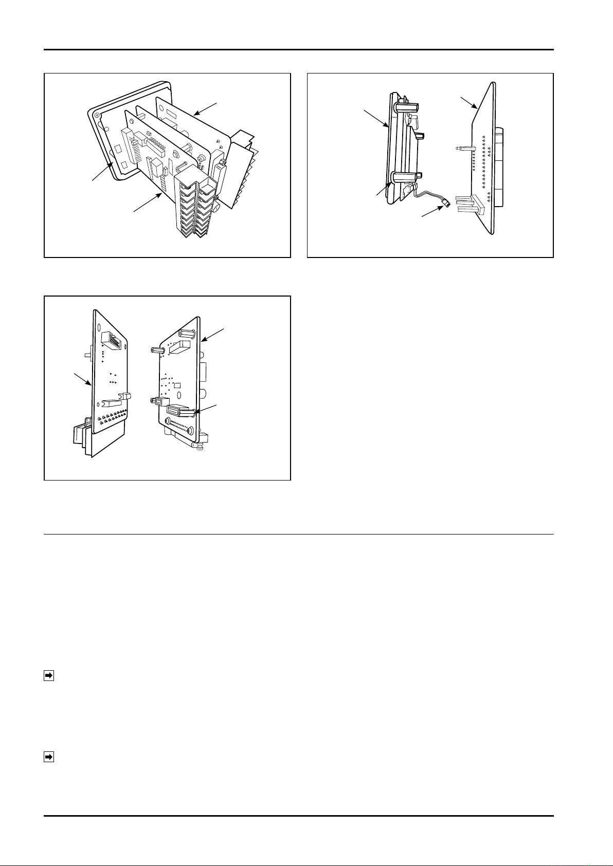
E-216-5N-E
Pull out the
output board
LCD module/
CPU board
Pull out power
supply/input board
Fig.9.7 Fig.9.8
(3) Pull out power supply/input board and output
board from CPU board.
Power supply
board
Input
board
CPU board
LCD
module
Installation
screw (x8)
Spacer (x4)
Harness
(4) LCD module/CPU board can be separated into LCD
module and CPU board by removing attaching
screws spacers and harness.
* Take care not to break the harness.
Attachment
screw (x8)
Spacer (x4)
Fig.9.9
(5) Power supply/input board can be separated into
po w er su p pl y and i np u t b oar d by rem o vi ng
installation screws/spacers.
9.4 Installation of internal assembly
9.4.1 How to assemble power supply/input board and output board
(1) Assemble LCD module and CPU board with display unit by securing fixation screws and spacers referencing
Fig. 9.8 shown in the previous section.
(2) For power supply board and input board, secure fixation screws and spacers referencing Fig. 9.9 shown in in
the previous section and insert a connector to assemble power supply/input board.
(3) Fit power supply/input board and output board in the groove in enclosure and insert each board until
contacting the rear surface of enclosure.
NOTE: Take care not to mistake board insertion position and direction.
9.4.2 How to assemble display unit
In the status shown in the previous section, insert the display unit. If LCD module and CPU board are
removed, assemble them preliminarily referencing Fig. 9.8.
(1) Connect CPU boards CN1 and CN2 to the mating connectors.
NOTE: 1. Reversed board cannot be attached.
2. Connect right and left connectors slowly and surely.
(2) After finish installing the front frame, secure four front frame/enclosure installation screws from terminal block
side.
36
Page 37
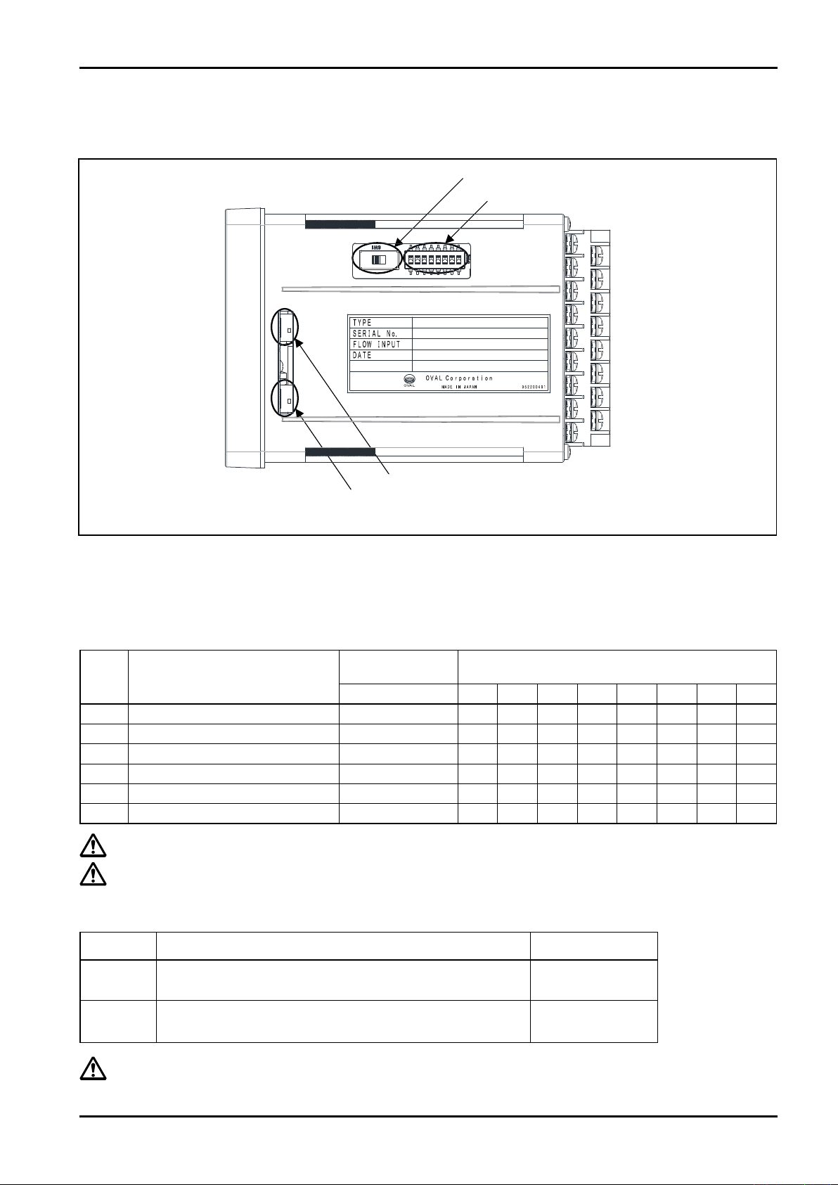
9.5 Change of setting on input board and CPU board
Input board SW1
Input board SW2
CPU board SW2
CPU board SW1
Switches on the input board and CPU board are located at the positions shown below.
E-216-5N-E
Fig. 9.10
The input board SW1 sets the power supply voltage of flowmeter transmitter and the input board SW2 sets the
type of input pulse from flowmeter (when you purchase the product, the setting is implemented depending on the
preliminarily specified type code).
The content of setting is shown below.
The setting can be changed following the content shown below.
Type
code
Voltage pulse/12V 2-wire or 3-wire
B
Current pulse/12V 2-wire
C
Current pulse/24V 2-wire
D
O.C pulse/12V 2-wire or 3-wire
G
Contact
K
Other than above
Z
CAUTION: Be sure to turn OFF the power supply to this device before changing the setting.
CAUTION: Do not change the jumper setting other than above.
Type of pulse
Transmitter power
supply SW1
SW1 1 2 3 4 5 6 7 8
3-2 ON OFF OFF OFF ON OFF OFF OFF
3-2 OFF ON OFF OFF OFF ON OFF OFF
1-2 ON OFF OFF ON ON OFF OFF OFF
3-2 ON OFF ON OFF ON OFF OFF OFF
3-2 ON OFF ON OFF ON OFF OFF ON
1-2 OFF ON OFF OFF OFF OFF ON OFF
Type of pulse SW2
Otherwise, it may cause a failure.
CPU board switch setting
Switch Description of signal Standard setting
SW1
SW2
CAUTION:
RS485/RS232C selected
1-2, 4-5 short-circuit: RS485 2-3, 5-6 short-circuit: RS232C
Communication termination resistance
1-2, 4-5 short-circuit: Yes 2-3, 5-6 short-circuit: No
2-3, 5-6 short-circuit
1-2, 4-5 short-circuit
Do not change the setting of switch on CPU board. Otherwise, it may cause a failure.
The communication is used only at adjustment at factory and maintenance and not used usually.
37
Page 38

E-216-5N-E
10. TROUBLESHOOTING
10.1 Inspection Items
NOTE:
Display is dead.
The device does not
operate even if
pressing the START
button
If trouble is found to be internal, check on the problem according to the table below and seek our service.
Problem What to check Possible causes
1. Inspect fuse.
2. Check supply voltage.
AC version 85 to 264VAC
1. Is the interlock lamp at display part
lighting?
2.
If the operation switch is set to external
operation for the parameter setting, are
terminals No.19 and 20 (external operation
input STOP contact b input) short-circuited?
3. Has the batch process been reset?
4. Check the items shown in "8.5 (4) Batch
start unavailable conditions".
5. When you press the START button, does
RUN lamp at display part light up?
6. Do valve control signals SV and MV
actuate property?
7. Are valve control signal wiring and supply
voltage correct?
8. Are valve operating and control pressure
settings correct?
1. Breaking of fuse (⇒ refer to section 10.2)
2. Supply voltage is incorrect.
3. A fault in the counter internal.
1. Short-circuit the terminals No.25 to 26
(interlock).
2. As STOP in the external operation input is
contact b, configure the circuit so that it is
turned OFF only when you want to stop
the operation temporarily.
3. Reset the batch processing.
4. Carry out the coping process shown in "8.5
(4) Batch start unavailable conditions".
5. If it does not light up, the internal of main
unit may be broken.
6. Valve control signal output relays are at
fault.
7. Valve control output lines are incorrectly
wired or an open in the cable.
8. Valve operating and control pressure
settings are incorrect.
Valve operates but the
total counter fails to
count.
Fails to perform batch
operation at the
setpoint.
Remote control
is inoperative.
1. Is a flowrate signal coming in from the
flowmeter?
2. Is the flow rate signal input within the
response frequency range?
1. Do valve control signals SV and MV
actuate when the target batch quantity is
reached?
2. If the quantity reaches the batch setting
quantity, do SV lamp OFF and END lamp
light up?
1. Can the batch quantity be set by operating
the front surface?
2. Is remote control circuitry wired correctly?
1. Incorrect wiring or an breaking of the cable.
A fault in the flowmeter itself or in the pulse
generator.
2. Outside the acceptable frequency range of
response.
Contact pulse Max 50Hz
Others Max 3kHz
1. Valve control signal output relay is at fault.
2. A fault in the counter internal.
1. If the setting is enabled by operating the
front surface, the parameter is not set to
external input.
Set the operation switch to external
operation by setting parameter.
2. Remote control circuitry is wired
incorrectly, or the cable has an open.
Or a fault in the counter internal.
38
Page 39
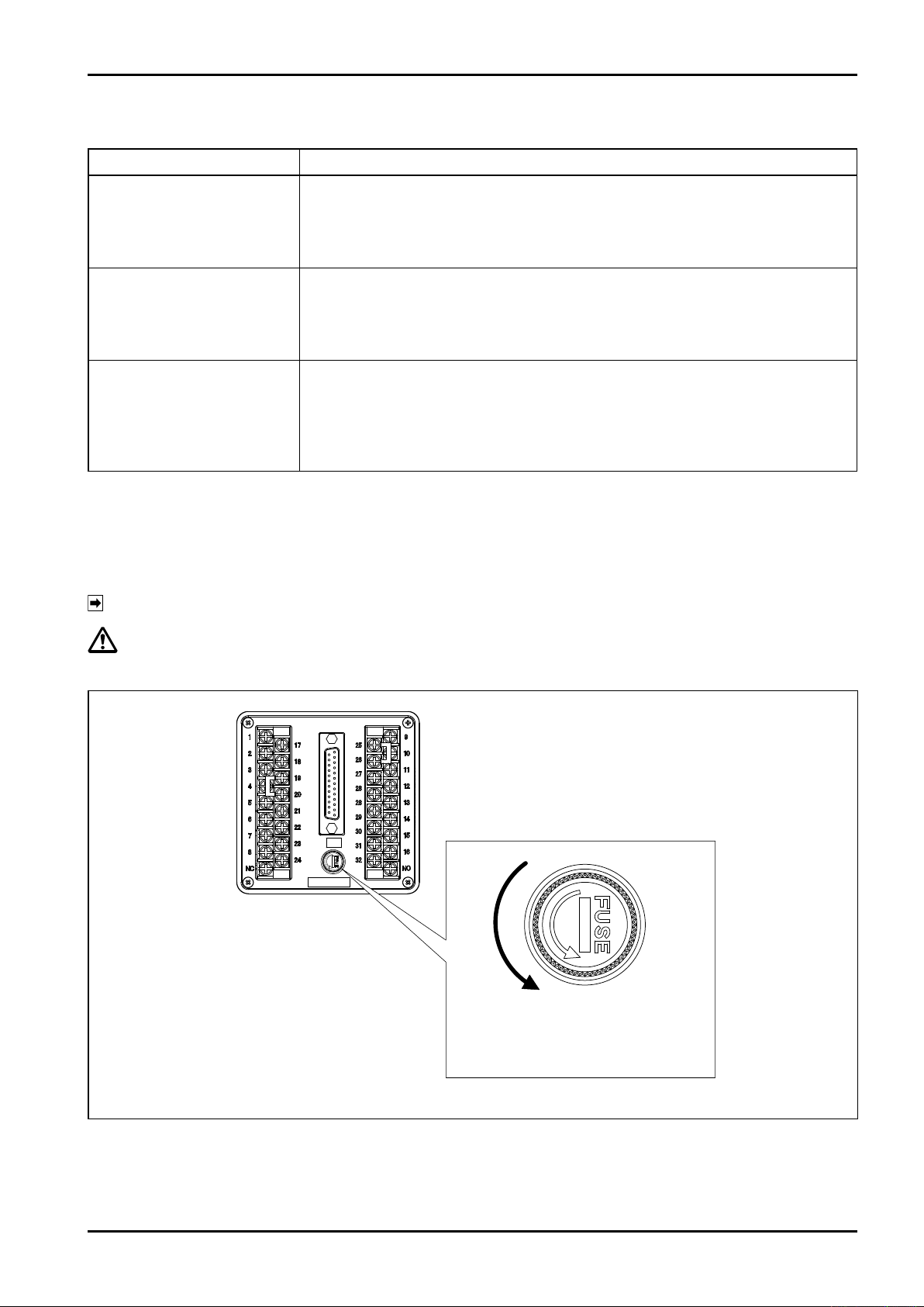
10.2 Q&A about Counter Behavior in Standby Mod
85〜264VAC
1A
Pushingthefuse,rotatetoward
thearroweddirection,andthen
pullitout
Questions Answers
・Counted. The accumulated total is also counted.
1. What if a pulse train arrives
in standby mode?
2. What if the counter counts
to the target batch setpoint
without pressing the
START?
・SV and MV valve signals remain inoperative (remain in the OFF).
・ If a leak error is set, a leak error is generated when a pulse of setting value or more
is input.
・Keep counting.
・Completion signal is not turned ON.
E-216-5N-E
3. While totalizing before
pressing START, is it
possible to start the
operation?
・ In the middle of totalizing, you can't commence START operation.
If even one pulse is input at the initial status, the operation cannot shift to the batch
processing directly.
Press RESET button once to reset the value to "0" (initial status), and then start the
operation.
10.3 Inspection of fuse
Disconnect the fuse socket on the rear surface of this device and inspect the glass fuse.
If the fuse blows out, disconnect it from the socket and replace it with a new one.
NOTE:
When you disconnect or attach the glass fuse, hold it softly. If you hold it strongly, it may be damaged.
CAUTION:
Do not use a fuse other than the rated.
Rating of fuse: 250V 1A
Fig. 10.1 Rear surface of the device and fuse socket
39
Page 40
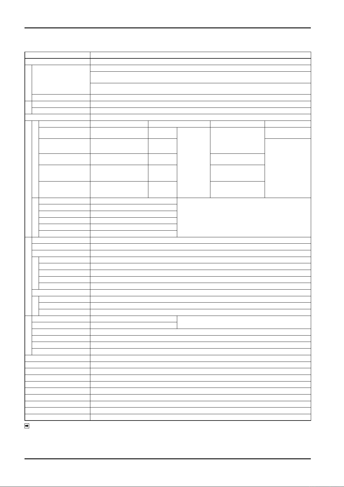
E-216-5N-E
11. GENERAL SPECIFICATIONS
Item Description
Type of operation
Display
Display
Operation status indicator
Channel select
Pushbutton switch
Buttons
Buzzer
Pulse type
2-wire/12V DC 3-wire
contact-closure pulse
2-wire/12V DC 3-wire
open collector pulse
2-wire/12V DC 3-wire
voltage pulse
Pulse Input
12V DC 2-wire
current pulse
24V DC 2-wire
Input Signal
current pulse
Start
Reset
Stop
Channel select
Set
Remote Input
InterLock
Meter factor setting
Input pulse freq.
Output pulse freq.
Batch setting
Initial setting
Final setting
Batch
Anticipated overshoot
Batch-end monitor setting
Parameter Setting
Pump output timer
Missing pulse interval
Overshoot
Alarm
Leak error setting value
Upper limit flow signal
Partial flow signal
Pump control signal
Batch-end signal
Alarm signal
Output Signal
Pulse signal
Power failure backup
Power source
Power consumption
Ambient temperature
Installation
Finish
Housing material
Outline dimensions
Weight
Noise resistance
※1: Varies depending on transmission distance and specication of the cable.
NOTE:
(e.g. 100m when open collector pulse with CVVS 1.25sq cable)
※2: To use the external operation input, it is necessary to prepare the connector of D-SUB25 pin by yourself and connect the circuit for selecting a channel to
D-SUB terminal on the rear surface of this machine.
※3: As special specication, pulse width 150μsec is possible.
When 150μsec output is selected, transmission distance will be limited depending on cable specication and receiving circuit.
(e.g. with CVVS 1.25sq cable and collector current 30mA, the transmission distance will be limited to 100m.)
Pulse addition
Batch total quantity display 6 digits
Batch setting quantity display 6 digits
Accumulated total value is displayed by TOTAL button 9 digits
Channel display 2 digits
Error code is displayed when an alarm is generated
RUN (yellow) / END (green) / ALARM (red) / interlock (blue) / measurement unit / total unit / MV (red) / SV (red) / PUMP (red)
Touch panel operation CH.1 to 9, CH.F (channel free) total 10 channels
Hard switch STOP/RESET/START form "a" contact
For generating alarm: electronic buzzer mounted on board
Connectable Transmitters Power to Transmitter Signal Level Freq. Response
PG20 13.5VDC
Coriolis owmeter (2-wire only)/
NPG60A (E3) FLOWPET-5G
PG30
NPG60A (F)
PG30S 13.5VDC
PA14/15/25
ULTRA OVAL
NPG60A (E)
Form "a" contact
Form "a" contact
Form "b" contact
BCD combination of 1 /2 /4 /8
Form "a" contact
Form "a" contact normally short-circuited
0.00010 to 1.99999 (Default: 1.00000)
Software frequency dividing: 1/1, 1/10, 1/100 (Default: 1/1)
Input synchronous (1ms or 50ms) software frequency dividing: 1/1, 1/10, 1/100 (Default: 1/1)
10 channels: 0 to 999999 counts (Only free setting channel can be changed from front surface.)
0 to 9999 counts (Default: 80)
0 to 9999 counts (Default: 80)
0 to 99 counts (Default: 2)
0 to 99 sec (Default: 5)
0 to 9999 sec (Default: 30)
0 to 999 sec (Default: 5)
0 to 99 counts (Default: 2)
0 to 99 counts (Default: 10)
Full-open signal MV
1-stage open signal SV
Relay contact (250V AC 1A) form "c" contact
Static relay (250V AC/DC 0.1A) form "a" contact
Relay contact (250V AC 1A) form "a" contact
Open collector NPN transistor output (35V DC 100mA) Pulse width: 1msec/ 50msec max. 3kHz (※3)
Saves data to FeRAM at power-off
85 to 264V AC 50/60Hz
25VA (Power consumed by the batch counter only, excluding power supply for MV/SV.)
−10 to +50℃
Panel mount type
Black (equivalent to Munsell N1.5)
Polycarbonate
96 (W) ×96 (H) ×142.1 (D) (batch counter body only)
Approx. 1kg (batch counter body only)
EMC EN55011 EN61000-6-2
13.5VDC
13.5VDC
24VDC
12VDC ON/OFF
(Input load resistance: 10kΩ)
Current
capacity: 55mA
(with short-circuit
protection)
Contact signal/Open collector signal
Contact current: 24V DC Max. 20mA
Instant signal "ON" width: 200msec
Instant signal "OFF" width: 200msec
Relay contact (250V AC 1A )
Refer to the operation chart for ON/OFF of form "c" contact.
"1": 5VDC and over
"0": 1.5VDC and below
"1": 20mADC
"0": 4mADC
Input load resistance: 510Ω
"1": 20mADC
"0": 4mADC
Input load resistance: 250Ω
(※2)
Max 3kHz (※1)
Max 50Hz
40
Page 41
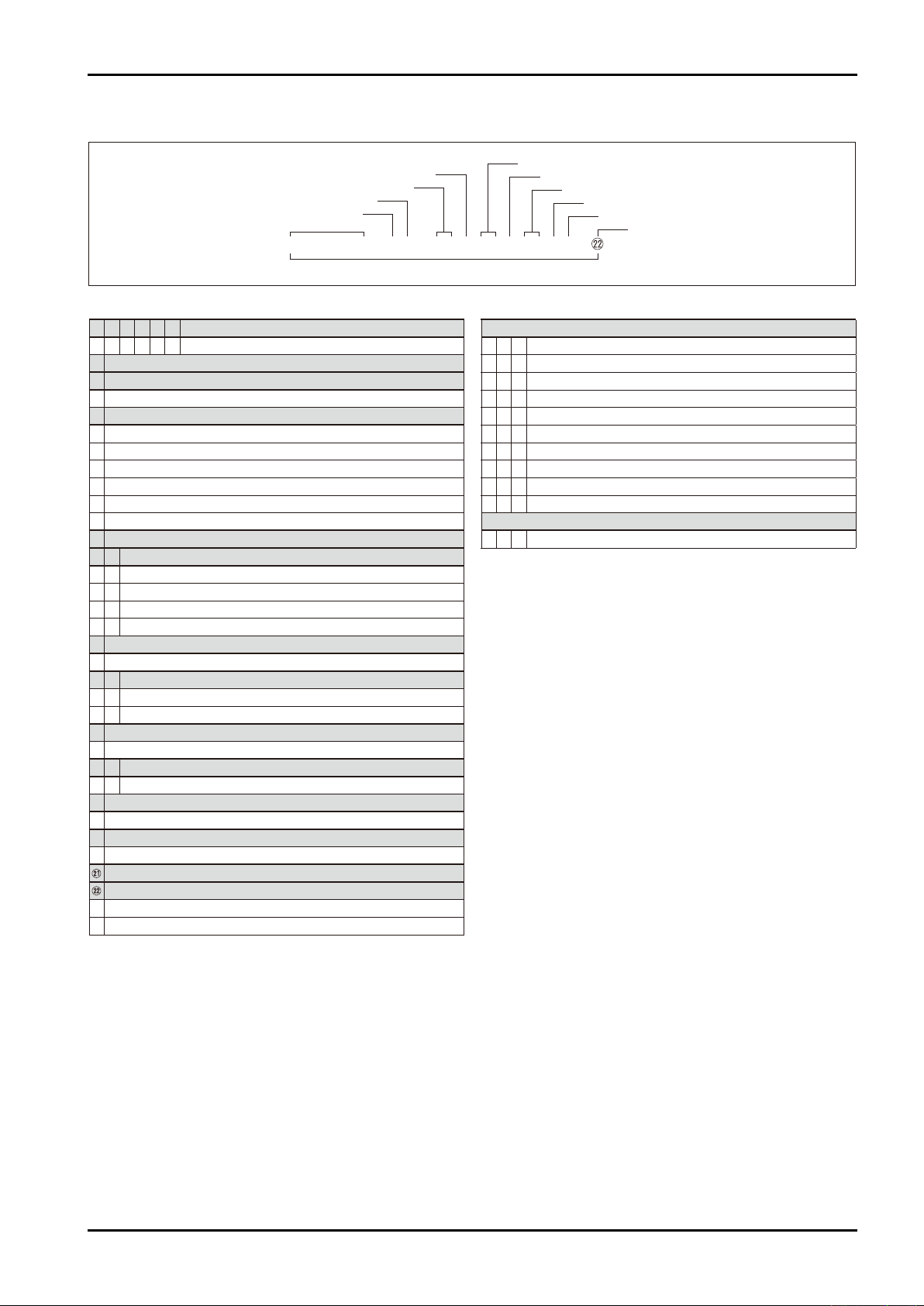
12. PRODUCT SYMBOL
●
Main code
① ② ③ ④ ⑤ ⑥
Model
E L 1 8 1 2 Batch counter/Non-explosionproof
⑦
⑧
Power supply
J 85〜264VAC 50/60Hz
⑨
Input signal
B Voltage pulse 12VDC 2 wires / 3 wires
C Current pulse 12V (PG30S)
D Current pulse 24VDC (4/20mA)
G Open collector pulse 12VDC 2 wires / 3 wires
K Contact pulse 12VDC 2 wires / 3 wires
Z Special
⑩
⑪ ⑫
Output item 1: Pulse output
B 1 Pulse width 1ms
B 5 Pulse width 50ms
S Y Input synchronous output
Z Z Special
⑬
Always N
N
⑭ ⑮
Output item 2: Pump output
C C c contact (Pump)
Z Z Special
⑯
Always N
N
⑰ ⑱
Always NN
N N Always NN
Always N
Always N
Always N
⑲
Always N
N
⑳
Version code
A Version A
Characteristic
0 Standard
Z Special
Document
D S J DWG and specifications for approval (Japanese)
D S E DWG and specifications for approval (English)
D R 0 Re-submission of DWG and specifications
D C J Final DWG (Japanese)
D C E Final DWG (English)
D W J Wiring diagram (Japanese)
D W E Wiring diagram (English)
D T J Inspection procedure (Japanese)
D T E Inspection procedure (English)
C B J Inspection certificate: B set
Witnessed by customer
V 1 0 Required
⑧−⑥⑤④③②① ⑯⑮⑭⑬⑫⑪−⑨ ⑰ −⑳⑲⑱
Model
Output item 1
Power supply
Input signal
Always N
Characteristic
Always NN
Version code
Output item 2
Always N
Always N
Main code
/ / / Additional code
●
Additional code
E-216-5N-E
41
Page 42

E-216-5N-E
All specifications are subject to change without notice for improvement.
2018. 04 Revised△
2017. 04 Released
E-216-5N-E (1)
 Loading...