

BATCH CONTROLLER
Ins. No. E-215-7-E
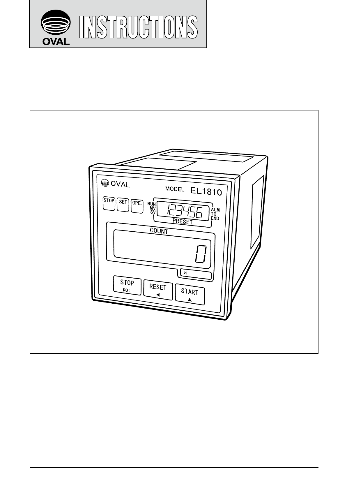
MODEL EL1810
Every OVAL batch controller is fabricated, tested, inspected, and shipped from our factory under stringent
quality control. In order to maintain its design performance throughout its life, this manual offers the
operator the necessary installation, operation and maintenance information.
Be well familiar with these instructions before you place the controller in service and keep this manual at
the eld location for ready reference.
Also refer to the instruction manual for the pulse generator (owmeter) used.
1

E-215-7-E
CONTENTS
1. BEFORE YOU BEGIN ................................................................................. 4
1.1 Conrming the Nameplate .............................................................................. 4
1.2 Transportation Considerations .......................................................................
1.3 Storage Considerations ..................................................................................
2. GENERAL ................................................................................................... 5
2.1 Features and Functions .................................................................................. 5
3. PART NAMES ............................................................................................. 5
4. INSTALLATION ........................................................................................... 6
4.1 Outline Dimensions ........................................................................................ 6
4.2 Installation ......................................................................................................
4.2.1 Installation Location (Indoor only) ........................................................
4.2.2 Panel ....................................................................................................
4.2.3 Installation ............................................................................................
4
4
6
6
6
6
5. WIRING ....................................................................................................... 7
5.1 Cables for Field Wiring ................................................................................... 7
5.2 Wiring Connections ........................................................................................
5.3 Identifying the External Connection Terminal Block .......................................
5.4 Identifying the External Connection Terminals ...............................................
5.5 Flowrate Input and their Terminals .................................................................
5.6 Flow Signal Input Wiring Connections ............................................................
5.7 Example of Hookup ......................................................................................
10
6. FRONT PANEL DISPLAY ......................................................................... 11
6.1 Front Panel Display Functions .......................................................................11
6.2 Control Key Functions (other than batch setup mode and other
setup mode) ..................................................................................................
6.3 Output Functions ..........................................................................................
12
13
7. BLOCK DIAGRAM .................................................................................... 16
8. OPERATION .............................................................................................. 17
8.1 Preparation Before Operation ....................................................................... 17
8.2 Preoperational Checks .................................................................................
8.3 Operation Sequence .....................................................................................
8.4 Conrming the Two-stage Valve Opening and Closure ................................
8.5 Description of Batch Operation .....................................................................
17
17
19
19
7
7
8
8
9
2

E-215-7-E
9. SETTING UP OR CHANGING PARAMETERS ........................................ 20
9.1 How to Change Parameters (batch setup and other setup modes) ............. 20
9.1.1 Batch Setup Mode ..............................................................................
9.1.1.1 Operation (batch setup mode) ............................................
9.1.1.2 Example of Batch Setup .....................................................
9.1.2 Setup Mode ........................................................................................
9.1.2.1 Operation (setup mode) ......................................................
9.2 Construction of Internal Assembly ................................................................
9.3 Removal of Internal Assembly ......................................................................
9.4 Assembling the Internal Assembly ................................................................
9.4.1 Installing the Power Supply Board and Output Board ........................
9.4.2 Installing the Front Panel ....................................................................
9.5 Setup or Change on the Power Supply Board
.............................................. 26
9.5.1 A change in the Power to Pulse Generator ........................................
9.5.2 Conguring the Flow Signal Input Circuit for the Companion
Pulse Generator .................................................................................
9.5.3 Input Frequency Division (hardware) Selection
.................................. 26
9.6 Setup on the Output Board ...........................................................................
9.6.1 Buzzer Sound Setup on Alarm (missing pulse, overmeasurement,
and parameter error) Detection ..........................................................
9.7 Reconguration on the Display Board ..........................................................
9.7.1 Total Counter Output Pulse Width Selection ......................................
20
20
21
22
23
24
24
25
25
25
26
26
27
27
27
27
10. TROUBLESHOOTING .............................................................................. 28
10.1 Inspection Items ......................................................................................... 28
10.2 Inspection of Fuse ......................................................................................
10.3 Dielectric Test Voltage ................................................................................
10.4 Q&A Controller Behavior in Standby Mode ................................................
29
29
29
11. GENERAL SPECIFICATIONS .................................................................. 30
12. PRODUCT CODE EXPLANATION ........................................................... 31
CONVENTIONS
Shown in this manual are the signal words NOTE, CAUTION and WARNING, as described in the
examples below:
NOTE: Notes are separated from the general text to bring the user’s attention to important
information.
CAUTION: Caution statements signal the user about hazards or unsafe practices which could
result in minor personal injury or product or property damages.
WARNING: Warning statements signal the user about hazards or unsafe practices which
could result in severe personal injury or death.
3
E-215-7-E
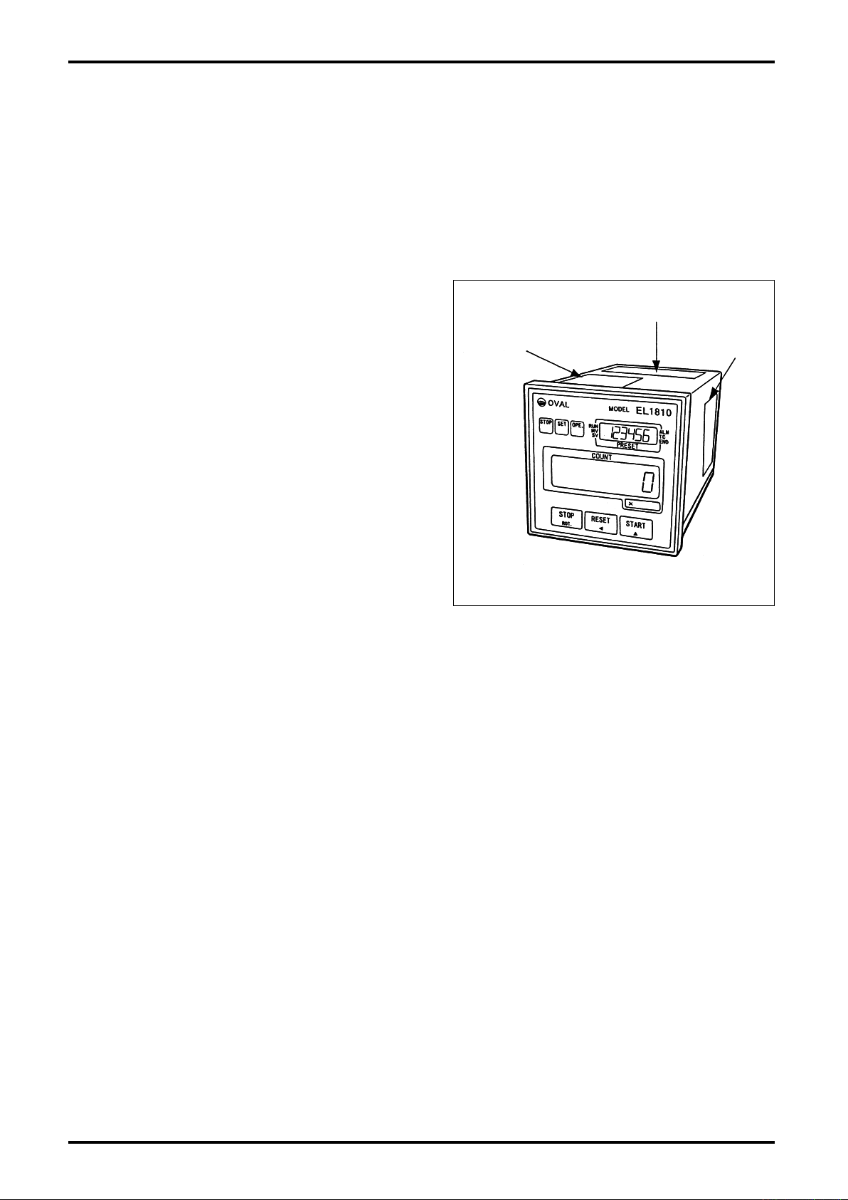
Nameplate
(product tag)
Terminal Identification label
Parameters
label
Fig. 1.1 Location of Nameplate
Nameplate
(product tag)
Terminal Identification label
Parameters
label
Fig. 1.1 Location of Nameplate
1. BEFORE YOU BEGIN
Before leaving the factory, every OVAL product is thoroughly inspected and tested and is shipped in rst-
class condition. When received, it should be carefully inspected for any indication of rough handling during
transit. In this section, instructions necessary for handling this instrument are described. Make yourself
familiar with these instructions. As for other instructions, refer to respective sections.
If you have something to inquire, contact the nearest OVAL authorized service station in your district.
1.1 Confirming the Nameplate
OVAL batch controllers are individually adjusted to the
customer specication.
Make sure, by comparing the model code and ratings
stated on the nameplate or tag attached to the top of
the housing against the GENERAL SPECIFICATIONS
(page 30) and PRODUCT CODE EXPLANATION (page
31), that the product you received conforms to the
specication in your order.
◆
When you inquire, please specify the product name,
model No., serial No., ratings, and other pertinent
information.
1.2 Transportation Considerations
(1) The batch controller should be transported and stored in the same package used for transportation
from our factory if circumstances permit.
(2) Avoid giving impact shocks to the batch controller during transportation.
1.3 Storage Considerations
If the batch controller upon receipt is to be stored for extended periods of time before installation,
unexpected problems could arise. In a case like this, the following considerations should be taken:
(1) The batch controller can best be stored in the original package used for transit from the factory.
(2) Select a storage location that meets the following requirements:
Free from rainwater and moisture
✩
Least vibration and impact shock
✩
In the room temperature and humidity environment (around 25°C and 65% R.H.)
✩
4
E-215-7-E
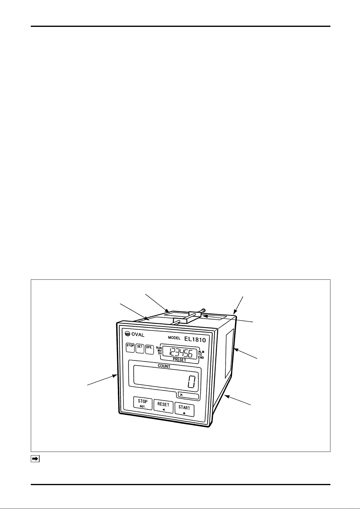
Nameplate
(product tag)
Front panel
Terminal Identification Label
Panel-mount Fitting
(two, top and bottom)
Backpanel (with terminal block
for external connections)
Parameter Label
Frames (top, bottom, right, left)
Fig. 3.1 Part Names
2. GENERAL
Combined with a owmeter and a shutoff valve, the batch controller passes a predetermined amount of the
process uid in batching operations. Built around a single chip microprocessor, this versatile, compact, and
lightweight controller is designed for ease of operation. It saves time and effort in many processes, such as
blending materials, dosing with additives, transferring materials from one tank to another, or shipping from
an outlet, at chemical, food, paint plants or elsewhere where streamlined production lines are desired.
2.1 Features and Functions
(1) Easy operation.
Front panel key switches for batch setup, start, stop, and reset for accurate operations.
(2) Accurate batch control.
Valve control output comes in two steps to open and shut off the valve for far more accurate metering
than with a single batch control output.
(3) Simple system conguration.
Can control the system with start, stop, and reset signal arriving from a remotely located point. Also
available is an end-of-batch signal. All these make interlocking with other control systems simple.
(4) Increased process safety.
Valve opens and shuts off in two steps (reducing the initial velocity); this arrangement prevents not
➀
only static electricity generation in the pipeline or in the tank at startup, but also water hammer, or
hydraulic shock, to the pipeline at valve closure.
If trouble occurs in the process for some reason, resulting in missing pulses, an overmeasurement,
➁
or parameter errors, an alarm can be made to go off.
(5) Reliable and simple to maintain.
Major circuits are built on printed circuit boards for reliability and simple maintenance.
➀
All inputs and outputs are isolated from each other by photocouplers.
➁
During power cycling, parameters and variables are retained in the E²PROM.
➂
3. PART NAMES
NOTES: 1. For terminal blocks for external connections, see Sec. 5.3 on page 7.
2. For the front panel display and controls, see Sec. 6.1 on page 11.
5
E-215-7-E
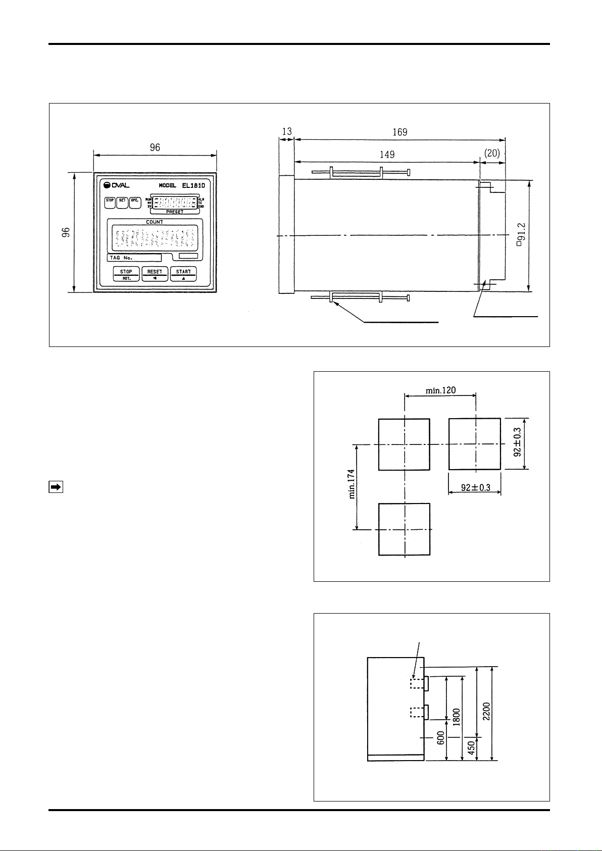
Terminal block
Panel-mount fitting
All dimensions in millimeters
Fig. 4.1 Outline Dimensions
All dimensions in millimeters
Fig. 4.2 Panel Cut
All dimensions in millimeters
Fig. 4.2 Panel Cut
All dimensions in millimeters
Batch controller
Fig. 4.3 Mounting Height
All dimensions in millimeters
Batch controller
Fig. 4.3 Mounting Height
4. INSTALLATION
4.1 Outline Dimensions
4.2 Installation
4.2.1 Installation Location (Indoor only)
Select an installation site where:
(1) Mechanical vibration, shock and corrosive gases
least exist.
(2) The air is dry and at around room temperature
and stable.
(3) A p l ace where is not e x p osed to the direc t
sunlight.
NOTE: Although the manufacturer guarantees
stated performance at ambient temperatures
from – 1 0 t o 5 0 ° C , i t is r e c o m m e n d e d t h a t
the ins trument be p laced in ser vice at room
temperature.
(4) Provide a sufficient working space behind the
instrument – at least 50 centimeters from the
back panel of the instrument to facilitate wiring
and servicing.
4.2.2 Panel
(1)
Use a rigid steel sheet with a minimum thickness of
1.6 millimeters. Recommended thickness is 3.2mm.
(2) If it is required to mount the computers side by
side, dimensions in Fig. 4.2 are suggested.
(3)
Recommended mounting height is given in Fig. 4.3.
4.2.3 Installation
(1) Insert the instrument through the opening in the
mounting panel.
(2) Hook the enclosure hold-down ttings to the slots
in the rear of the enclosure and, conrming that
the instrument is positioned on a level plane,
secure the instrument to the panel with panel-
mount ttings (Fig. 4.1).
6
E-215-7-E
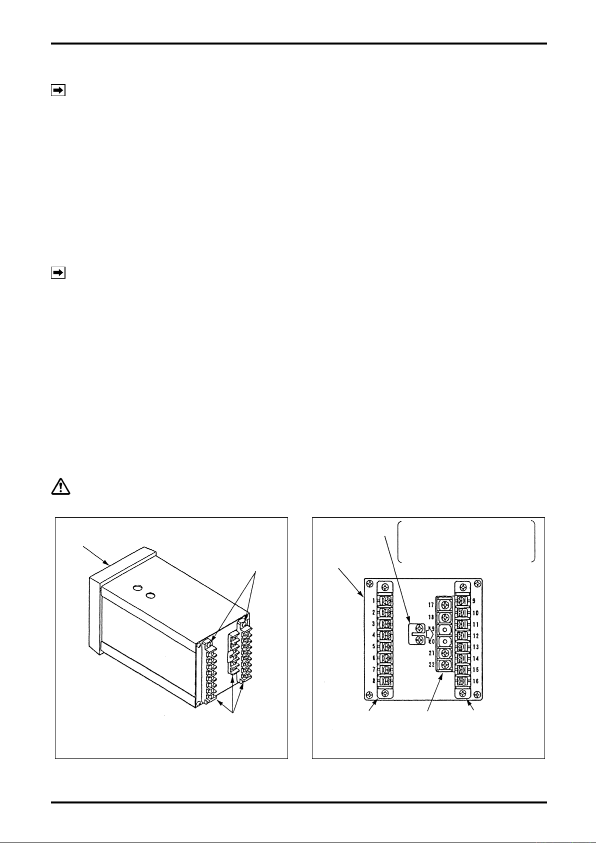
Front panel
Terminal block
fitting screws
Terminal block for
EXT. connections
Fig. 5.1
Fig. 5.2
Shorting strip If remote operate input STOP is
unused, short out terminals
STOP (19) and COM (20) with
this strip.
Terminal
Nos. 1-8
Rear panel
Terminal
Nos. 17-22
Terminal
Nos. 9-16
5. WIRING
NOTE: See “WIRING” in the pulse generator instruction manual.
5.1 Cables for Field Wiring
(1) For flowmeter input signal cable, electrostatically shielded, polyethylene insulated, vinyl-sheathed
control cables (CVES, 1.25 to 2mm
For output signal cables, insulated, vinyl-sheathed cables (CVV, CVS … JIS C 3401) are suggested.
(2) Cable shields must be connected to terminal “G” of the controller. At the probe end, leave the shield
wire end unprepared.
5.2 Wiring Connections
(1) Conduit work is suggested for eld wiring.
NOTE: In conduit work, use separate conduit for power cables and signal cables in order to minimize
the possibility of stray current pickup.
(2) Route cables sufciently away from other power lines or power circuits, if any, to reduce the possibility
of inductive interference to a minimum.
(3) Use crimp-style terminal lugs for connections and ensure good electrical contact. Connection terminals
are found at rear of the controller (Fig. 5.1).
(4) In applications where an inductive load (valve, counter, etc.) is driven, do not fail to use a surge
suppressor (see Fig. 5.3).
(5) Give a 30-centimeter approx. allowance to the wiring harness to allow internal assembly withdrawal for
servicing.
2
, 2- or 3-conductor), or equivalent, must be used.
5.3 Identifying the External Connection Terminal Block
At the rear of the controller, terminal block (terminal Nos. 17-22) secured to the output board and removable
terminals block (terminals Nos. 1-8, 9-16) secured with four screws are found.
CAUTION: Before making wiring connections, verify the validity of flowmeter (pulse generator)
and receiving instrument combination by referring to their product No., tag No., etc.
7
E-215-7-E
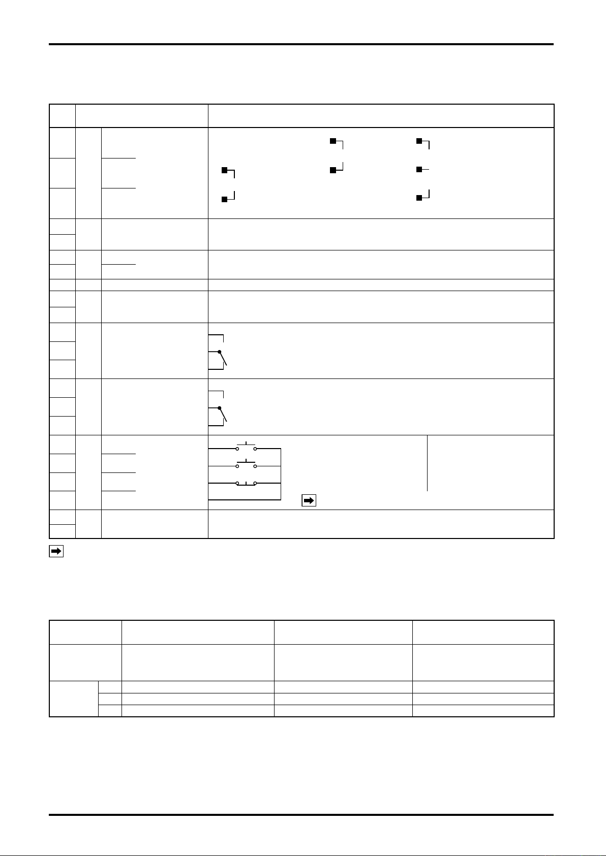
Current pulse
[PA14, 15, 25,
NPG60A (E)]
Contact-closure pulse
Open collector pulse
2-wire voltage pulse
(PG20, Coriolis meter)
3-wire open collector
3-wire voltage pulse
[PG30, NPG60A (F),
60 (E3), FLOWPET- EG]
Partial-flow signal (SV): Initial open signal
Relaycontact output, a set of Form “c” contact Capacity: 250VAC, 1A
a
c
b
a
c
b
Upper-limit flow signal (MV): Full-open signal
Relay contact output, a set of Form “c” contact Capacity: 250VAC, 1A
a
a
b
5.4 Identifying the External Connection Terminals
Table 5.1
Term.
No.
Label Required Conditions for Connections and Specications
1
2 SIG.
3 COM.
4
5
6
7 L2 (–)
8 GND Ground terminal
9
10
11
12
13
14
15
16
17
18
19
20 COM.
21
22
SUP.
FLOW SIG
INPUT
Flow Signal Input
TOTAL COUNT OUTPUT
External
Totalizer
Output to
L1 (+)
Power
BATCH END OUTPUT Non-contact relay output, a set of Form “a” contact Capacity: 250V AC/DC 0.15A
Batch
Output
End-of-
VALVE OPERATION
SIGNAL (SV)
Signal
Valve Control
VALVE OPERATION
SIGNAL (MV)
Signal
Valve Control
START
RESET
Input
STOP
Remote Control
ALARM OUTPUT
Alarm
Output
POWER
SUPPLY
REMOTE
CONTROL
INPUT
Non-contact relay output, a set of Form “a” contact Capacity: 250V AC/DC 0.15A
Output pulse width: 1ms (standard) or 50ms
85 to 264VAC 50/60Hz
An output on detection of missing pulses, overmeasurement, parameter error Relay
contact output, Form “a” output Capacity: 250V AC, 1A
Contact current:
START: Form “a” contact
RESET: Form “a” contact
STOP: Form “b” contact
NOTE: Short STOP when not in use.
10mA max. at 15VDC
Signal width:
Instantaneous signal
※:
1 sec.
NOTE ※: Provide at least 2 seconds between individual signals (see page 10).
5.5 Flowrate Input and their Terminals
Table 5.2
Signal Type
Generator PG20, Coriolis owmeter PA 14, 15, 25, NPG60A (E)
Terminals
: Terminals in use
○
8
Contact-closure Pulse, 2-wire
Voltage Pulse, Open Collector Pulse
1
2
3
—— ○
+
○
–
○
Current pulse
3-wire open collector pulse
3-wire voltage pulse
PG30, NPG60A (F),
NPG60A (E3),
FLOWPET-EG
+
–
○
—— ○
SUP.
○
SIG.
○
COM. (0V)
5.6 Flow Signal Input Wiring Connections
Contact-closure
pulse
NOTE:
This does not mean to accept three
different types of pulse generators
at the same time.
EL1810
Terminal block
EL1810
Terminal block
Current pulse
Open collector
Pulse
Voltage pulse
Pulse generator
Pulse generator
Fig. 5.3
Fig. 5.4
EL1810
Terminal block
Current pulse
Pulse generator
Fig. 5.4
EL1810
Terminal block
Pulse generator
Fig. 5.5
E-215-7-E
(1) C o n t act - c l osu r e p uls e , 2-w i r e vol t a g e
pulse,open collector pulse (PG20, Coriolis
owmeter)
(2) Current pulse [(PA14, 15, 25, NPG60A(E)]
(3) 3-wire open collector pulse
3-wire voltage pulse
[PG30, NPG60A (F), NPG60A (E3), FLOWPET-EG]
CAUTION: Before making wiring connections, verify the validity of flowmeter (pulse generator)
and receiving instrument combination by referring to their product No., tag No., etc.
9
E-215-7-E
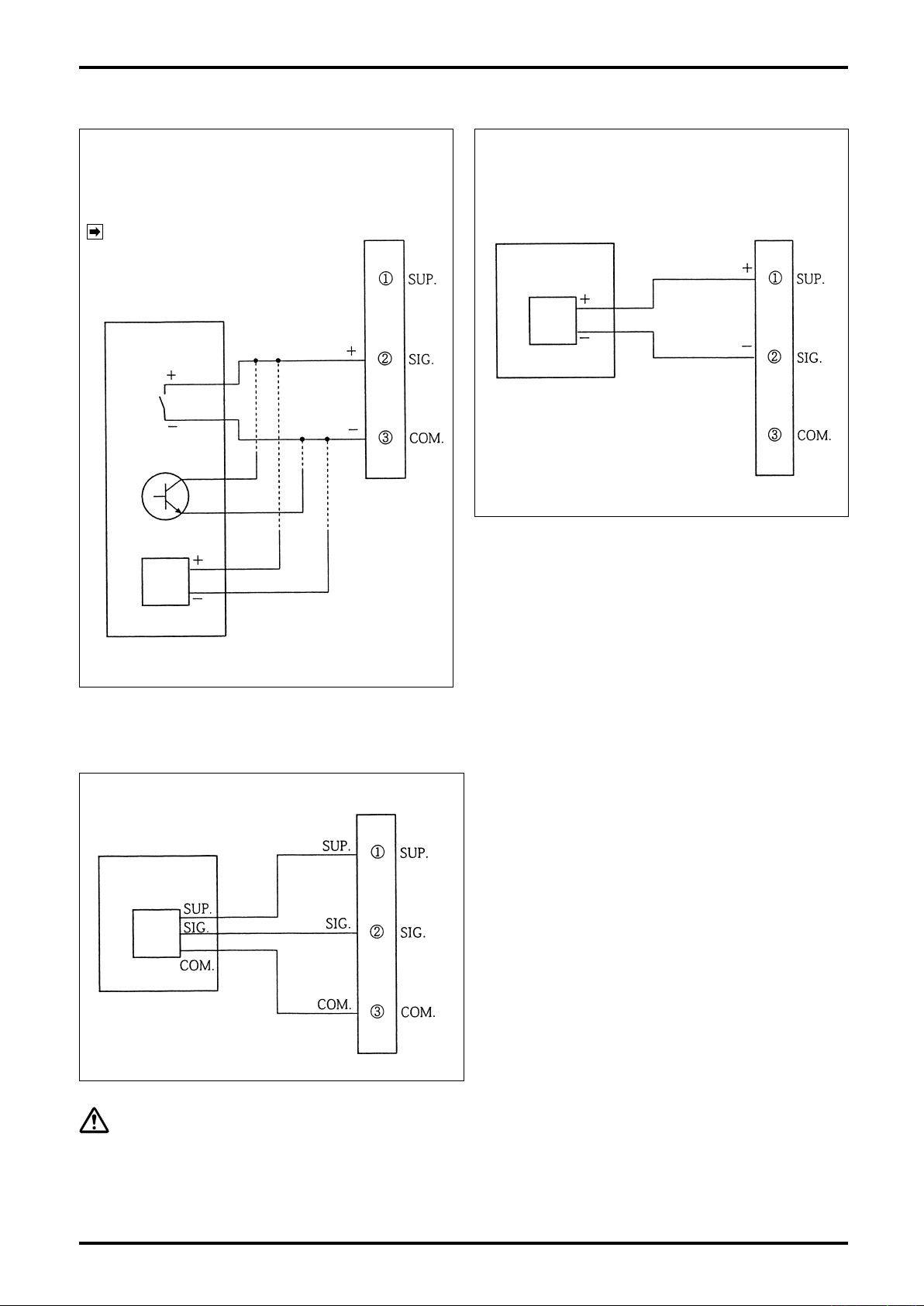
OVAL flowmeters, Coriolis flowmeters, etc.
1ms (std.) or 50ms
ON duration
1 sec.
1 sec.
3-way
directional
valve
Combination
filter/reducing valve
Surge suppressor
Ratings
R: 120Ω
C:
0.1μF 250V AC
Air
supply
1 sec.
2 sec.
min.
2 sec.
min.
Signal duration
Power: 85 to 264V AC, 50/60Hz
Fig. 5.6 Example of Wiring Connections
Output to remote
totalizer counter, etc.
(Non-contact relay output,
Form “a” contact)
End-of-batch output,
LED indicator. etc.
(Non-contact relay output,
Form “a” contact)
START : Form “a” contact)
RESET : Form “a” contact)
STOP : Form “b” contact)
Power
Valve
Alarm output (missing pulses, overmeasurement,
parameter error, or other fault)
Can activate an LED indicator, etc.
(Relay contact output, Form “a” contact)
Two-stage shutoff valve
Flow signal input
Coriolis flowmeter
External connection terminal block
(at the top of controller)
OVAL
FLOWMETER
5.7 Example of Hookup
NOTE: Remote command inputs and front-panel
buttons have their functions in common.
See Sec. 8.3 “Operation Sequence” for
signal input procedures.
CAUTION
If remo te c ontrol i nput is n ot use d,
always shor t across STO P (19 ) and
COM. (20).
10
CAUTION
Coup le a surg e s uppres s or, e t c. i n
parallel with inductive load.
(R: 120Ω C: 0.1μF 250V AC)

E-215-7-E
Operation Indicators
(RUN, MV, SV)
Operation status indicator LEDs
STOP (RED), SET (ORG), OPE (GRN)
Operation indicators
(ALM, TC, END)
Tag No. plate
Control keys
STOP (ROT.) RESET () START ()
Fig. 6.1 Front Panel Displays and Controls
Measurement unit label
LCD2 display
Batch setting (8-digit)
LCD1 display
s4ARGETBATCHSETPOINTDIGIT
Displays target batch setpoint only,
while batch process is in progress.
s'RANDTOTALDIGIT
s25.INDICATORSSTANDTHSEGMENTS
light up.)
6. FRONT PANEL DISPLAY
6.1 Front Panel Display Functions
The front panel has three control keys – STOP/ROT., RESET◀, START/▲ at the bottom and three LED
status indicators – STOP, SET, OPE (red, orange, green) at top left. The upper LCD 1 is an 8-digit display
with 7mm high characters and the central LCD 2 is an 8-digit display with 12.7mm high characters.
Labels Functions
STOP Stays on while the batch process is stopped.
LED indicator
LED 1 display
NOTES: ※1. For information about the batch setup mode, see Section 9.1 on page 20.
CAUTION:
SET Comes on while the batch setpoint is changed. ※1
OPE. Stays on while the batch process is in progress.
RUN Blinks on and off while power is on (in normal operation).
SV, MV Comes on in response to valve control signal output SV or MV. (Stays on until reset.)
ALM
TC Blinks in synchronism with each totalizer count and its output to the remote counter.
END Comes on at the end of batch. (Stays on until reset.)
※
2. ALM does not light upon detection of a parameter error.
RUN, SV, MV, ALM, TC
segments in its 1st and 8th digit. The display shows the batch setting on the 6-digit
Comes on while an alarm output (missing pulse, overmeasurement) is produced.
(Stays on until reset.) ※2
, and
are indic ated usin g the LCD 1 hor izon tal
END
display field, excluding these 1st and 8th digits at both ends.
In the grand total mode, the display becomes a full 8-digit counter.
11

E-215-7-E
6.2 Control Key Functions (other than batch setup mode and other setup mode)
NOTE: For control key locations, see Fig. 6.1 on page 11.
STOP
ROT.
Batch in progress
Upon detection of missing
pulses
LCD1 shows target batch
setpoint or grand total.
Key functions
Item Functions
Batch stops (
Missing pulses alarm output is reset (LCD 1
LCD 1 screen switches:
Batch setpoint (6-digit) + LED 1 operation indicators
RUN , SV , MV , ALM , TC , END ,
Shown alternately.
Grand total reading (8-digit)
OPE : goes out; Valve control signals SV, MV: close;
LCD 1
SV , MV : go out).
ALM : goes out).
CAUTION: You cannot switch the display from the batch setting to the grand total unless you
ALM
, end-of-
RESET
◀
reset the current batch process by resetting the missing pulse alarm
batch
END
, and overmeasurement alarm
ALM
.
Key functions
Item Functions
LCD 1 shows grand total.
LCD 1 shows batch setpoint
(not in operation)
START
LCD 1 shows grand total.
LCD 1 shows batch setpoint
(not in operation).
Key functions
▲
Item Functions
None
Batch process reset (LCD 2 batch reading is reset to zero).
End-of-batch output is reset (LCD 1
Overmeasurement alarm output is reset (LCD1
Parameter error alarm output is reset.
None
Simultaneously with the start of a batch process (OPE. : comes on),
valve operate signal SV opens (LCD 1
CAUTION: Simultaneously with
1 SV comes on). If the two-stage open mode remains disabled, the valve operate
signal MV also opens (LCD1 MV comes on), however.
END : goes out).
ALM : goes out).
SV : comes on).
illumination, the valve operate signal SV opens (LCD
OPE.
12

E-215-7-E
[Batch in progress]
Flow pulse signal stop Missing pulse alarm detected
STOP key
(alarm reset)
START key
(Restart)
Missing pulse duration set
ALM indicator
Alarm output
SV, MV indicator/output
Batch end output
Fig. 6.2
RESET key
(alarm reset/
batch total reset)
START key
(Batch start)
Fig. 6.3
Batch end
Overmeasurement preset
Overmeasurement alarm detected
ALM indicator
Alarm output
SV, MV indicator/output
Batch end output
6.3 Output Functions
NOTE: For the information about the front panel display functions not described in this section, see
Section 6.1 on page 11 and Table 11.1 on page 30.
(1) Alarm Output
Upon detection of missing pulse, overmeasurement, or parameter error, the controller produces an alarm
output.
The LCD 1
completes a circuit across terminals 21 and 22 (Relay contact output Form “a” contact) (upon detection of
all alarms).
a. Missing pulse alarm detection (Fig. 6.2)
Following
arrives within the time preset for missing pulse detection, an alarm output is produced. Immediately after
startup, however, time measurement begins approximately 5 seconds later.
For the setup procedure, refer to Sec. 9.1.
ALM
START
▲
then comes on (only upon detection of missing pulses or overmeasurement) and
key depression to start a batching process, if no ow pulse signal (terminals 1-2-3)
b. Overmeasurement alarm detection (Fig. 6.3)
When a ow pulse signal arrives while a batch process is in progress, a target batch quantity will eventually
be reached and an end-of-batch signal is generated. If ow pulses continue to arrive at this point and
exceed a preset overmeasurement quantity, an alarm output is produced.
For the setup procedure, refer to Sec. 9.1.
13

E-215-7-E
STOP key
(Confirm param.)
RESET key
(Initialize param.)
Parameter error alarm detected
ALM indicator
Reestablish param.Alarm output
“dAtA Err” indicator
Fig. 6.4
STOP
ROT.
PressParameters
s"ATCHSETTINGhBvAPPEARSATLEFTEND
s"ATCHTOTALCOUNT
s'RANDTOTALCOUNT
s3CALEFACTOR
s&REQUENCYREDUCTION
s)NITIALSETTING
s&INALSETTING
s-ISSINGPULSESETTING
s/VERSHOOTSETTING
KEY $ISPLAYEDALTERNATELY
&IG
Messages upon detection of a parameter error alarm
c. Parameter error alarm detection (Fig. 6.4)
When an error in any of parameter settings is found, an alarm output is produced and a data error
message “DATA Err” appears on the display (the LCD 1
Each time
•
STOP
ROT.
key is pressed, the LCD 1 display scrolls through the available data, enabling the
operator to identity which parameter causes a problem (see Fig. 6.5).
ALM
does not come on in this case).
Following the error identification, press
•
RESET
◀
key to cancel the alarm output.
(A message “DATA Err” disappears and all the data are reset (initialized).)
Following the reset step above, set up the parameters of interest and the target batch quantity once
•
again according to the specification. See Sec. 9.1 for the setup procedure.
14

E-215-7-E
(2) End-of-batch output
When a ow signal reaches the target batch quantity during a batch process, an output is produced.
The LCD 1
output, Form “a” contact).
(3) Scaler
If incoming pulse signal is of unfactored pulses, a constant inherent to the owmeter used is multiplied in
the scaler; conversion takes place into quantities in industrial engineering units of measure in integer; the
resultant quantities are used for batch processes.
For the setup procedure, refer to Sec. 9.1.
(4) Input frequency division (scaling)
There are two approaches in setting up the input frequency division. One is a frequency reduction by
hardware, using a jumper and the other is a frequency reduction by software, using the front panel control
keys.
For the setup procedure, refer to Sec. 9.1 and 9.5.
END
then comes on and completes a circuit across terminals 9 and 10 (Non-contact relay
15

E-215-7-E
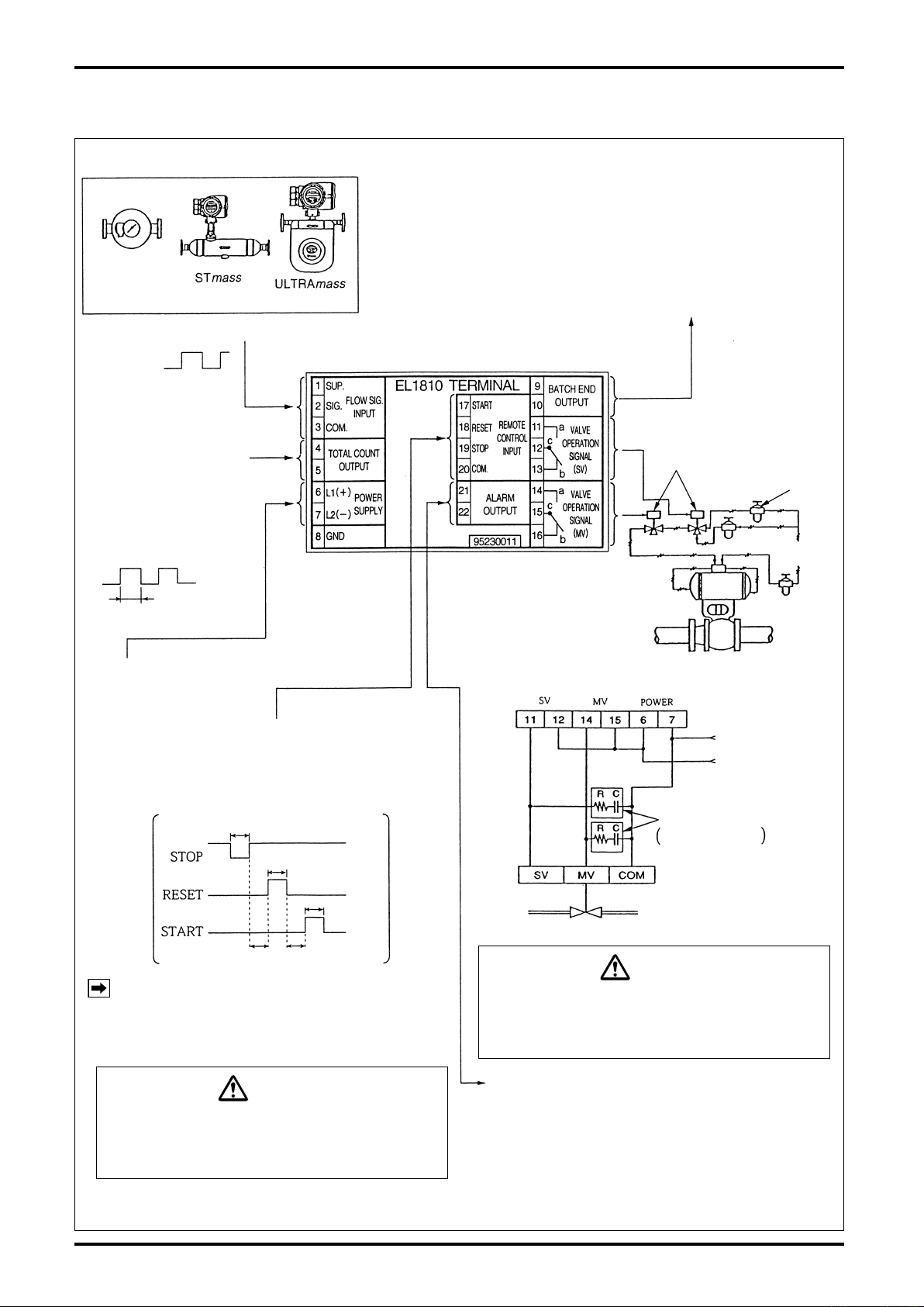
LCD 2 Disp. (batch reading 8-digit) LCD 1 Disp. (batch setting 6-digit)
Power to generator
Flowrate signal
input
Remote control input
Power
1,3
4,5
9,10
21,22
11 to 16
2
17,18,19
20
6,7
24V
13.5V
START
RESET
STOP
85 to 264VDC
50/60Hz
Power to
generator
Wave-
shape
Regulated
Voltage
source
Power to
generator
Freq.
divide
Freq.
divide
One-shot
multivibrator
1ms or
50ms
Batching
microprocessor
6-digit
Batch counter
8-digit
Total counter
Scaler
Front-panel
control keys
Display boardPower board Output board
Non-contact
relay
Non-contact
relay
Relay
Relay
Output to external total counter
TC
Non-contact relay output
Form “a” contact
End-of-batch output
END
Non-contact relay output
Form “a” contact
Alarm output
ALM
Relay contact output
Form “a” contact
(missing pulse, overshoot,
param. error)
Valve control signals
SV, MV
Relay output
Form “c” contact, one set each
NOTES
Missing
pulse alarm
Overmeasure
alarm
Com-
pare
Batch setting
Initial setting
Final setting
6-digit
0 to 999 counts
0: No setting
Default: 80 counts
Toggle
switch
RUN ⇔ SET
RUN: Run mode
SET : Setup mode
Buzzer
Counter
About A
0 to 15 sec.
0: No alarm
Default: 10 sec.
About B
0 to 99 counts
0: No alarm
Std.: 10 counts
7. BLOCK DIAGRAM
16

E-215-7-E
key
key
key
Fig. 8.1
key
key
key
Fig. 8.1
8. OPERATION
8.1 Preparation Before Operation
(1) Make sure to see that the controller and associated equipment are correctly installed, connected and
wired with no place left unnished.
WARNING
Make sure to see that the power terminals are connected to a source of the rated voltage.
Connecting an incorrect power voltage source may ruin the controller.
(2) Make sure that the shutoff valve is correctly wired and set. For details, see the instruction manual for
the shutoff valve.
8.2 Preoperational Checks
Make sure to see that the shutoff valve operates properly without allowing the flow.
•
(Run this check daily before operation.)
(1) Supply power to the controller. Conrm that LED
STOP indicator becomes illuminated and that
displays LCD 1 and LCD 2 come on.
(2) Enter some arbitrarily set quantity of a batch.
NOTE: See Section 9.1.1.2, “Example of Bach
Setup” on page 21.
(3) Press
shutoff valve opens.
(4) Press
valve closes properly.
(5) Repeat steps (3) and (4) above several times to make certain that the shutoff valve opens and closes
properly.
(6) If the controller features remote start and stop, repeat steps (3), (4) and (5) above also at the remotely
located point.
START
STOP
ROT.
key to make c e r t a in that the
▲
key to make certain that the shutoff
8.3 Operation Sequence
(For information about the control keys, see Section 6. FRONT PANEL DISPLAY on page 12.)
(1) Turn on power.
(2) Allow the LCD 1 display to show the batch setting.
(3) Set the target batch quantity desired.
The unit of measure is indicated on the unit label at lower right below the LCD 2 display.
(4) Press
(5) Press
RESET
◀
START
▲
key to reset the batch total counter of LCD 2.
key to start up and the controller will start batching operations.
CAUTION
If the controller receives even a single pulse during the transitional time between RESET key
and START key depressions, it will fail to start. (For details, see Question 3 in Section 10.4
Q&A Controller Behavior in Standby Mode.)
17

E-215-7-E
(6) To perform a repeated metering of the last measured batch, all you need is to press the reset key to
bring the total counter of LCD 2 back to zero and then press the start key:
Press
Pressing
NOTE: For metering different batches, select a new target batch setting each time.
(7) Emergency shutoff (or temporary interruption)
To bring the controller to an emergency stop, press
closure.
Pressing
point of interruption.
In this way, safe and accurate measurement can be achieved.
RESET
◀
START
▲
START
▲
key to reset the total counter.
key readies to restart the last metered measurement.
STOP
ROT.
key will resume operation and continue metering the remaining quantity from the
key. The shutoff valve will come to a full
18

E-215-7-E
Fig. 8.2 Operation Time Chart
Valve
control
signals
Partial flow signal
(Partial open signal)
High limit
flow signal
(Full open signal)
High limit flow open
(MV: LCD 1 comes on.)
Partial flow open
(SV: LCD 1 1comes on.)
High limit flowrate
Flow
rate
Initial flowrate
Initial partial flow
(Initial setting)
START
signal
STOP
signal
Time
Final flowrate
Overshoot
End of batch
Batch setting
(Target quantity)
Final partial flow
(Final setting)
8.4 Confirming the Two-stage Valve Opening and Closure
You can conrm the valve opening and closing in two stages by one of the following two approaches:
Once set the initial and final setpoint at “0,” choose a batch setpoint somewhere above “1” and press
•
START
▲
If simulated pulses (from OVAL pulse checker PC2201, for example) are available, you can confirm
•
and
STOP
ROT.
key to verify proper shutoff valve actuation.
proper batch operation of the shutoff valve by setting the initial and final setpoint at any point, pressing
START
key, and then feeding a simulated pulse train.
▲
NOTE: The target batch setting should be greater than the sum of the initial and nal setting.
8.5 Description of Batch Operation
NOTE: Operation can best be understood by referring to the operation time chart in Fig. 8.2 below.
Upon depression of
predetermined quantity (from point A to point B) has been delivered, the valve opens fully; when metering
has reached point C, the valve automatically throttles the flow and maintains a predetermined valve
position (nal owrate).
At point D, a closure signal is generated. However, due to a time lag in valve actuation, inherent to the
type of valve used, the valve actually close at point E. If an overshoot, or overmeasurement, exceeds a
predetermined quantity, the controller produces an alarm.
Safe and accurate measurement is thus achieved. In this connection, valve positions A → B and C → D
must be preselected on the part of the valve.
START
▲
key, the valve opens to a predetermined position (initial owrate). When a
19

E-215-7-E
Batch Setup Mode
comes on and LCD 1 (batch setting) blinks.
6 digits
Batch
setting
Change
Figure adjust Shift Setup
A numerical value is finalized
with two control keys.
To RUN mode
omes on.
To exit without changing any setting
9. SETTING UP OR CHANGING PARAMETERS
Setting up parameters and variables other than those to be set up with controller’s front-panel control keys
requires internal assembly removal since it involves conguring the internal boards of the controller.
NOTE: Defaults (your specications inclusive) appear on the parameter settings label attached to the
side of the controller. ⇒ See page 22.
9.1 How to Change Parameters (batch setup and other setup modes)
9.1.1 Batch Setup Mode
To set up a batch, holding
STOP
ROT.
key depressed for more than 3 seconds while the following conditions
are met.
The front LED SET lights up and the LCD 1 (batch setting) blinks on and off. Target batch setpoint
alteration is now acceptable.
Conditions required for changing batch setpoints
(1) The display does not show the grand total.
(2) A missing pulse alarm has not been detected along with its output.
(3) An overshoot alarm has not been detected along with its output.
(4) An end-of-batch signal has not been produced.
(5) A batch operation is not in progress.
CAUTION: 1. If an alarm output exists, reset it before you work.
2. While the controller is not in the batch operation but is only counting
incoming flow pulses for totalization, a change in batch setting is
acceptable.
9.1.1.1 Operation (batch setup mode)
On seeing the front panel SET illuminated and the whole LCD 1 ickering (in response to the procedure
above), you can change the current setpoint by the following procedure.
Upon depression of
back to the RUN mode.
STOP
ROT.
key, the value entered is stored in the memory and the LCD 1 display goes
20

E-215-7-E
Hold key depressed for more than 3 seconds.
START
▲
RESET
STOP
ROT.
STOP
ROT.
STOP
ROT.
Blinks at the previous
setpoint.
Batch setup mode
comes on and LCD (batch setpoint) blinks.
In the operations below, absence of any key entry
for more than 10 seconds will cause the LCD to
return to the previous setting and to RUN mode
automatically (in the batch setup mode).
Set up from the most
significant digit:
“1” in this example.
If the figure has gone too far,
press the key a number of
times to readjust the figure.
If the figure has gone too far,
press the key a number of
times to readjust the figure.
If the figure has gone too far,
press the key a number of
times to readjust the figure.
Press
once.
Press
once.
Press
once.
Press
once.
Press
once.
Press
thrice.
LCD1 Disp.: 0 → 1
LCD1 Disp.: 0 → 10
LCD1 Disp.: 10 → 12
LCD1 Disp.: 12 → 120
LCD1 Disp.: 120 → 123
LCD1 Disp.: 123 →1230
If you have taken the figure place up more than necessary,
like 1→10→100, press key a number of times until the LCD 1 display shows 0 and go back to → to
start all over again.
Press
twice.
If figure place has been taken
up more than necessary,
If figure place has been taken
up more than necessary,
In a similar way, keep on adjusting the figure at the rightmost of the LCD 1
with and taking the figure place up with key.
Adjust the figure until the LCD 1 displays 123456
and press key.
At touch of key, the figure is stored in the memory and the LCD display returns to the normal batch display.
SET
RESET
◀
STOP
ROT.
◀
9.1.1.2 Example of Batch Setup
Make sure that your batch setting meets the conditions required for changing batch setpoints outlined in
the previous paragraph.
To change batch setpoints, we recommend to press
shows 0 (ZERO) and then set up as outlined below.
●
Shown below is an example of setting of a batch of 123456.
RESET
◀
a number of times until the LCD displays
21

E-215-7-E
Output board
Take off two setscrews
securing the terminal
block and separate the
terminal block forward.
Terminal block
(Terminals 9 thru 16)
Rear of Batch Controller
Parameter settings label
Fig. 9.1
Toggle Switch
CAUTION
Be sure to turn off power before you work.
9.1.2 Setup Mode
CAUTION: Be sure to turn off power before you work.
Remove the terminal block holding terminals Nos. 9 through 16 and place toggle switch S1 at ★ mark in
Fig. 9.1 in the “SET”.
Turning power on will bring the controller into the setup and the entire LCD will icker.
In this setup mode, the following parameters can be congured. [Factory default settings appear on the
setup label attached to the side of the controller. See Fig. 9.1.]
NOTE: The controller is shipped at default settings unless otherwise specied by the customer.
CAUTION
During a batch process, in an interrupted or completed state of operation, or in an alarmed
condition, a transfer to the setup mode is disabled. Cancel the batch process or clear the
alarmed event by pressing RESET button first before you retry.
Table 9.1
Symbol Item Setup range Default setting
Total reading reset
(gure adjustment)
F Scale Factor 0.0001 to 1.9999
d Frequency division 0: 1/1, 1: 1/10, 2: 1/100 Default:0 (1/1) or customer’s specication
oP Initial setting
Final setting
cL
Missing pulse
PL
setting
oV Overshoot setting
00000000 to 99999999
0 to 999 counts
(Set to 0: Two-stage open disabled;
SV and MV open simultaneously.)
0 to 999 counts
(Set to 0: Two-stage close disabled;
SV and MV close simultaneously.)
0 to15sec
(Set to 0: Missing pulse alarm
detection disabled)
0 to 99 counts
(Set to 0: Overmeasurement alarm
detection disabled)
——
Meter factor the meter used
Default: 1.0000 or customer’s specication
or customer’s specication
or customer’s specication
or customer’s specication
or customer’s specication
Default: 80
Default: 80
Default: 10
Default: 10
22

E-215-7-E
Setup Mode LCD1 blinks.
If you go down to the next step without any
setpoint changes.
00000000
to 99999999
(8-digit)
Total counter setting at 0
Total
reading
Change
Change
Change
Change
Change
Change
Change
Adjust
numerals.
Shift Setup
Set up numeric value
with two control keys.
0.001
to 1.9999
Scale factor at 1.0000
Scaler
0:1/1 1:1/10
2:1/100
Frequency divide at 0 (1/1)
Freq.
divide
0 to 999
counts
(3-digit)
Initial setting at 80
Initial
setting
0 to 999
counts
(3-digit)
Final setting at 80
Final
setting
0 to 15 sec
(2-digit)
Missing pulse setting at 10 sec.
Missing
pulse
setting
0 to 99
counts
(2-digit)
Overmeasure setting at 10
Overmeas.
setting
9.1.2.1 Operation (setup mode)
On seeing that the entire front panel LCD1 is blinking (by the previously outlined steps), you can change
parameters and variables as follows. The procedure to enter a numerical value remains the same as
“Example of Batch Setup” in the previous section. Refer to that section. The LCD 1 readings shown below
are factory default settings.
CAUTION:
Upon completion of all setup procedures, turn off power and return the toggle
switch to “RUN”.
23

E-215-7-E
Display board
Front panel
Interconnect cable unit
Output board
Power supply board
Rear panel
Guide slot to hold the boards
(top and bottom)
Terminal block
(9-16)
Terminal block (17-22)
Terminal block (1-8)
Fitting screws (a total of 4)
Frame
Fig. 9.2
Fig. 9.3
Long screw
Fig. 9.4
Front panel
Display board
Separate.
9.2 Construction of Internal Assembly
The internal assembly of this controller consists of three boards – display board, power supply board, and
output board. The power supply board and output boards are individually coupled with connectors CN1 and
CN2 to their mating connectors CN1 and CN2 on the display board. The rear panel has terminal blocks for
external connections. (For details of the terminal blocks, see Sections 5.3 and 5.4.)
NOTE ※: Since the power board and output board are
connected with interconnect cable unit, slide
both of them out of the frame when you remove
them.
9.3 Removal of Internal Assembly
Remove the controller from the mounting panel before its internal assembly is removed.
CAUTION:
Take off long screws at back of the controller.
➀
24
Be sure to remove power before you work.
Separate the front panel (display board) from the
➁
housing.

E-215-7-E
Fig. 9.5
Separate.
Output board
Power supply board
Rear panel
Power supply board
terminal block
Fig. 9.6
Output board
Shorting strip
Fig. 9.7
Separate.
Output board
Output board
terminal block
Rear Panel
Power supply board
Extract the power supply board from the terminal
➂
block on the rear panel.
If a shortin g strip e x i sts, remo v e i t b efore
➄
extracting the output board from the terminal
block of rear panel.
9.4 Assembling the Internal Assembly
Make sure of a shorting strip which may possibly
➃
exist on the terminal block of rear panel before
extracting the output board.
9.4.1 Installing the Power Supply Board and Output Board
NOTE:
Install the output board and power supply board into the terminal block.
➀
NOTE: Installation is correct if the power supply board and output board face each other with their
Install the power supply board and output board into the groove of top and bottom frames until the rear
➁
panel of terminal blocks comes in contact with the frames.
9.4.2 Installing the Front Panel
In the state described in the previous section, install the front panel in place.
With the two boards installed on the top and bottom frames, press the rear panel to connect CN1 and
➀
CN2 of the display board with their mating connectors.
NOTES: 1. Misplaced board cannot be installed properly.
Upon completion of front panel attachment, install four long screws from the side of terminal block.
➁
If a shorting strip is attached to the terminal block of the output board, remove it before
assembly.
component parts.
2. Take your time to ensure correct engagement of the right and left connectors.
25

E-215-7-E
Fig.9.8 Power Supply Board
(an example of J1, J2, J3 positions)
Card edge connector
to slide into the terminal
block
Power supply board
13.5V
24V
J1
J2
J3
2
12
1
Fig.9.8 Power Supply Board
(an example of J1, J2, J3 positions)
Card edge connector
to slide into the terminal
block
Power supply board
13.5V
24V
J1
J2
J3
2
12
1
Fig.9.9 Power Board (an example of J4 setting)
Power supply board
Fig.9.9 Power Board (an example of J4 setting)
Power supply board
9.5 Setup or Change on the Power Supply Board
NOTE: Remove the power supply board before you set up.
CAUTION: Do not forget to remove power to the instrument before you work.
9.5.1 A change in the Power to Pulse Generator
A change in the power to the pulse
generator is made by changing jumper
J1 positions (4-coupled) on the power
supply board between 13.5V and 24V.
NOTE: Do not fail to replace all four
sockets at the same time.
J1 , J2, and J3 in Fig. 9.8
show an example of jumper
positions.
9.5.2 Configuring the Flow Signal Input Circuit for the Companion Pulse Generator
Referring to Table 9.2, set up the ow signal input
circuit for the companion pulse generator.
(See Fig. 9.8 for the location of jumpers J1, J2,
and J3.)
Companion pulse generator
Companion pulse generator
Contact-closure PG20 13.5V 1 2
Contact-closure PG20 13.5V 1 2
2-wire open collector 13.5V 1 1
2-wire open collector 13.5V 1 1
3-wire open
3-wire open
collector
collector
Voltage pulse
Voltage pulse
Current pulse
Current pulse
FLOWPET-EG,
FLOWPET-EG,
NPG60A(E3)
NPG60A(E3)
PG30,
PG30,
NPG60A(F),
NPG60A(F),
Coriolis owmeter
Coriolis owmeter
PA14, 15, 25,
PA14, 15, 25,
NPG60A(E)
NPG60A(E)
Table 9.2
Table 9.2
Power to pulse
Power to pulse
generator, J1
generator, J1
13.5V
13.5V
13.5V
13.5V
24V 2 1
24V 2 1
J2 J3
J2 J3
1 1
1 1
1 1
1 1
9.5.3 Input Frequency Division (hardware) Selection
Input frequency division (hardware) is
set up by selecting the position of
jumper J4 on the power supply board
for 1/1, 1/10, or 1/100.
Install the jumper socket into one of
positions 1/1, 1/10, or 1/100.
J4 in Fi g . 9. 9 s ho w s 1/ 1 ( def a u l t
setting).
26

E-215-7-E
Output board
Fig. 9.10 Output board (an example of J1 setting)
Output board
Fig. 9.10 Output board (an example of J1 setting)
Display board
Fig. 9.11 Display Board
Display board
Fig. 9.11 Display Board
9.6 Setup on the Output Board
NOTE: Remove the output board before conguring the board.
CAUTION: Do not forget to remove power to the instrument before you work.
9.6.1 Buzzer Sound Setup on Alarm (missing pulse, overmeasurement, and parameter
error) Detection
Buzzer sound upon alarm detection (missing
pulse, overmeasurement, and parameter error)
is set up by selecting the position of jumper J1.
Set the jumper J1 on the output board in the
position desired, referring to Table 9.3.
J1 i n Fig. 9.10 s hows t he stan dard ( 1-2)
position.
Table 9.3
Jumper Description
J1
1 – 2
2 – 3 Buzzer disabled
Buzzer sound (default)
NOTE: As for toggle switch S1 in Fig .9.10, refer to Sec. 9.1.2 on page 22.
9.7 Reconfiguration on the Display Board
NOTE: Work with the display board LCD (front panel) removed.
9.7.1 Total Counter Output Pulse Width Selection
Jumper (J1) located on the display board
selects the total counter output pulse width.
Set the position of jumper J1 on the display
board shown in the sketch at right to choose
between two pulse width positions according
to Table 9.4.
Table 9.4
Jumper Description
J1
1 side
50 side Pulse width 50ms
Pulse width 1ms (default)
27

E-215-7-E
10. TROUBLESHOOTING
10.1 Inspection Items
NOTE: If trouble is found to be internal, isolate the problem according to the table below and seek our
service.
Table10.1
Symptom Inspect Possible causes
Display is dead. 1. Inspect fuse.
2. Check supply voltage.
AC version 85 to 264VAC
Valve fails to
respond to
START
depression.
▲
key
1. Check to see if terminals 19 and 20 (remote
control input Stop, From “b” contact) on the
terminal block are shorted.
2. Dose
Does LCD
3. Do valve control signals SV and MV actuate
SV : 11, 12, 13 on the terminal block
MV: 14, 15, 16 on the terminal block
OPE
START
▲
property?
key depression?
come on in response to
SV come on at the same time?
1. Fuse is blown. (⇒ See page 29.)
2. Supply voltage is incorrect.
3. A fault in the controller.
1. Unless terminal 19 and 20 (remote control input
STOP) on the terminal block are shorted by a
switch having a Form “b” contact or a shorting
STOP
strip,
ROT.
leaving that key inoperative.
2. A fault in the controller.
3. Valve control signal output relays are at fault.
key always remains depressed,
Valve operates
but the total
counter fails to
count.
Fails to perform
batch operation
at the setpoint.
Remote control
is inoperative.
4. Isn’t the batch set to 0?
4. At touch of key
START
an end-of-batch signal
▲
is produced at once.
5. Are valve control signal wiring and supply voltage
correct?
6. Are valve operating and control pressure settings
correct?
7. Has the batch process been reset?
(Alarm reset, end-of-batch output reset, etc.)
1. Is a owrate signal coming in from the owmeter? 1. Incorrect wiring or an open in the cable.
2. Is the incoming owrate signal within the
acceptable frequency range of response?
1. Do valve control signals SV and MV actuate
when the target batch quantity is reached?
2. Does LCD
when the target batch quantity is reached?
1. Is it possible to control with front panel control
keys?
2. Is remote control circuitry wired correctly? 2. Remote control circuitry is wired incorrectly, or
SV go out and LCD END come on
5. Valve control output lines are incorrectly wired or
an open in the cable.
6. Valve operating and control pressure settings are
incorrect.
7. Reset the batch process.
A fault in the owmeter itself or in the pulse
generator.
2. Outside the acceptable frequency range of
response. (The microprocessor accepts pulses
up to 200Hz.)
1. Valve control signal output relay is at fault.
2. A fault in the controller.
1. Remote control signals are incorrect if
controllable with front panel control keys.
the cable has an open.
Or a fault in the controller.
28

10.2 Inspection of Fuse
Fig. 10.1 Power Board and Fuse
Power supply board
Fuse cover
Holder
Glass-cartridge fuse
Fig. 10.1 Power Board and Fuse
Power supply board
Fuse cover
Holder
Glass-cartridge fuse
Remove the fuse cover on the power supply
board and inspect the glass cartridge fuse
(see Sec. 9.3 on pages 24 and 25 for power
supply board removal).
If the fuse is blown, extract from its holder
and replace it with a new one.
NOTE: When y ou remo v e and ins t all
a glass cartridge fuse, avoid
gripping it too hard. Too hard a
grip may crush the glass.
CAUTION: Do not use fuses of other rating.
E-215-7-E
10.3 Dielectric Test Voltage
A surge protector is incorporated in this controller: Do not attempt to conduct a dielectric withstanding
voltage test across power terminals.
10.4 Q&A Controller Behavior in Standby Mode
Questions and answers with the controller EL1810 in standby mode (
pressed) are given in Table 10.2.
1. What if a pulse train arrives
2. What if the counter counts
3. While the counter keeps
Table 10.2
Questions Answers
•
Counts. “TC” segment in LCD 1 display blinks in sync with incoming pulses.
in standby mode?
to the target batch setpoint
without pressing the
START?
counting without pressing
the START, what happens
if START is pressed?
Both the LCD 1 grand total counter and LCD 2 batch counter count.
•
SV and MV valve signals remain inoperative (remain in the OFF).
•
“END” segment in LCD 1 display comes on with BATCH END OUTPUT across terminals
•
– ➉ closed.
➈
The counter keeps counting even beyond the target batch setpoint.
However, if overshoot alarm is enabled, “ALARM” segment comes on at that setpoint and
ALARM OUTPUT contacts across terminals – come to close.
To reset, press
To restart while a batch process is in progress is inhibited.
•
Once the counter has started counting, even for a single count, from the initial state, a
transfer to the batch process is inhibited. Press
state) before you start.
NOTE: Except that frequency reduction d is set to “0” and, at the same time, scale F is
RESET
set to any value larger than “1”, the counter will remain at “0” in response to just
a single pulse arrival. In this case,
◀
key.
START
▲
RESET
◀
key remains under-
key once to return to “0” (initial
Pressing
RESET
◀
key once again is required.
29

E-215-7-E
11. GENERAL SPECIFICATIONS
Table 11.1
Item Description
Type of operation Pulse adding
Displays 7-segment 8-digit LCD × 2 (LCD 1 numerals 7mm high, LCD 2 numerals 12.7mm high)
Target batch setting readout LCD 2 shows to the 8th digit (resettable with RESET key). Batch setting to the 6th digit.
Grand total LCD 1 shows 8 digits
RUN, SV, MV, END, TC, ALM: LCD segments light.
•
Operating status indicators
Pulse generator Power to generator Signal levels Response speed
Contact-closure pulse PG20
2-wire open collector pulse Corioli owmeter
3-wire open collector pulse
Voltage pulse
Flow signal input
Current pulse PA14, 15, 25. NPG60A(E) 24VDC
Input signal
Start Instant make, Form “a” contact
Stop Instant make, Form “a” contact
Remote
Reset Instant break, Form ”b” contact
Batch setting
Grand total setting
Initial-and nal-count setting
Missing pulse setting
Overshoot setting
Parameter setting
Scaler setting
Frequency divide setting
Partial ow signal
Valve operate
signal
End-of-batch output
Output to remote totalizer
Output signal
Alarm output
Power failure back up Parameters and variables retained in E²PROM when power is interrupted.
Power source 85 to 264VAC, 50/60HZ
Power consumption 25VA 10W max.
Ambient temperature –10 to +50°C
Installation Panel mount
Finish Munsell N1.5 (standard)
Outline dimensions 96 × 96 × 170mm
Weight 1.0kg approx.
(SV)
High-limit ow
signal (MV)
Missing pulse
➀
Overshoot
➁
Parameter
➂
error
OPE (GRN), SET (ORG), STOP (RED): LED lights.
•
BATT: “BATT” mark in the LCD lights.
•
13.5VDC ON/OFF
FLOWPET-DG,
NPG60A (E3)
PG30, NPG60A(F),
Corioli owmeter
Any setting from 0 to 999999 counts
Preset by front-panel control keys (in the batch setup mode “RUN”).
Any setting from 00000000 to 99999999 counts
Preset by front-panel control keys (in the setup mode “SET”).
Any setting from 0 to 999 counts (default: 80) Set by front-panel control keys.
If set at “0,” the valve opens and closes in the single stage ( in the setup mode “SET”).
Any setting from 1 to 15 sec. (default 10 sec.) Preset by front-panel control keys.
When set to “0,” the alarm is disabled (in the setup mode “SET”).
Any setting from 1 to 99 counts (default 10) preset by front-panel control keys.
If set to “0,” the alarm is disabled (in the setup mode “SET”).
Any setting from 0.0001 to 1.9999 (default 1.0000) Preset by front-panel control keys (in the setup
mode “SET”).
Software frequency division – 0:1/1, 1:1/10, 2: 1/100
•
One chosen with front-panel control keys (in the setup mode “SET”).
Hardware frequency division – 1/1, 1/10, 1/100
•
One chosen with internal jumper (in the setup mode “SET”).
Holds from batch start to batch end.
“SV” area in the LCD lights. “S. VALVE” area in the LED lights.•
Holds from the end of initial partial ow to the start of nal partial Flow
open.
“MV” area in the LCD lights. “M. VALVE” area in the LED lights.•
Holds when the target batch setting is reached.
“End” area in the LCD lights. (Resettable with RESET key.)•
Pulse width: 1ms (default) or 50ms
“TC” area in the LCD blinks in synchronism with the output.•
Operates when no pulse is accepted within preset time.
“ALM” area in the LCD lights. (Resettable with STOP key.)•
Operates when both target batch and this setting are exceeded.
“ALM” area in the LCD lights. (Resettable with RESET button.)•
Operates upon detection of a parameter error.
A message “dAtA Err” appears. (Resettable with RESET key.)•
13.5VDC
Current
capacity
55mA
Contact-Closure signal or open collector signal
Contact current: 10mA max. at 15VDC
Instant signal width: 1 sec.
Note: Provide 2 sec. min. between signals.
(input load resistance:
10kΩ)
“1”: 5VDC min.
“0”: 1.5VDC max.
“1”: 20mADC
“0”: 4mADC
(Input resist: 24Ω)
Relay contact output
(Form “c” contact)
Contact capacity:
250VAC 1A
One set each
Non-contact relay output
(Form “a” contact)
Contact capacity:
250VAC/DC 0.15A
One set each
Relay contact output
(Form “a” contact)
One set
Contact capacity: 250VAC, 1A
An alarm output is
produced when any of
alarms ① , ② , or ③ has
occurred.
50Hz max.
200Hz max.
Input pulse
frequency
reduction
1/10…2kHz max.
1/100…3kHz max.
NOTE: A surge protector is built in: do not make insulation resistance test and dielectric withstanding
voltage test across power terminals.
30

12. PRODUCT CODE EXPLANATION
E-215-7-E
Table 12.1
Item
Product Code CodeSufx Code
➀ ➁ ➂ ➃ ➄ ➅−➆ ➇ ➈ ➉
Model E L 1 8 1 0 −
Power supply 7
4
Input signal
Actuation mode 1
Additional function I 1
Additional function II
Finish of frame 1
Version C
7
9
5
9
⑬
Description
Batch Controller
85 to 264V AC, 50/60Hz
4/20mA DC current pulse
Contact-closure, open collector, voltage pulse
Other than above
Add: Counts up from “0.”
Al arm ou tput (missi ng pul ses, ove rme asurement,
parameter error)
Output to an external totalizer
+ end-of-batch output
Other than above
Munsell N1.5 (standard)
31

E-215-7-E
All specications are subject to change without notice for improvement.
2016.05 Revised
2003.05
E-215-7-E(1)
Released
△
 Loading...