

Oval Delta Flowpet FLX B Instructions Manual
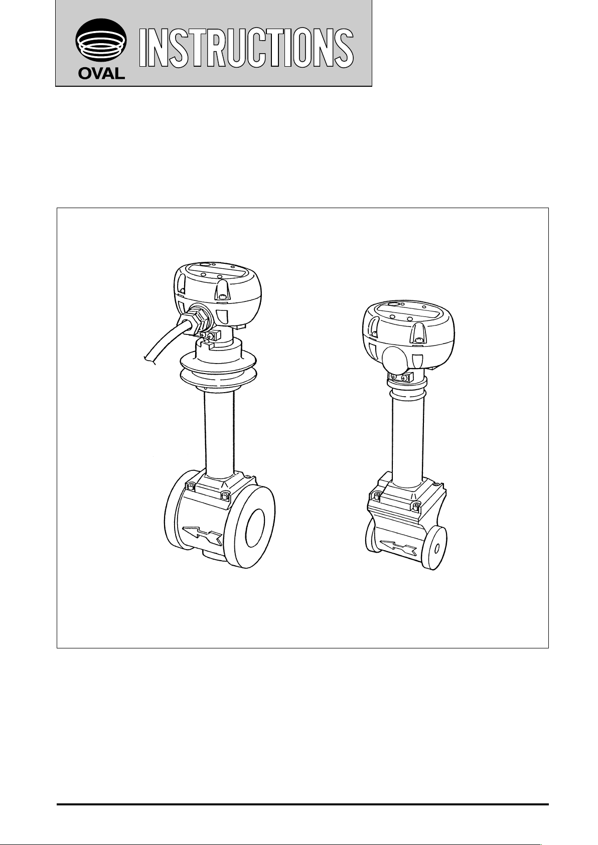
Vortex Flowmeter
DELTA FLOWPET
Ins. No.
D-555-3-E
MODEL : FLX
£££−£££
B
High temperature type
(radiator ns provided)
Every OVAL vortex owmeter DELTA FLOWPET is fabricated and shipped from our factory under stringent
quality control. In order to maintain its design performance throughout its life, this manual offers the operator
the necessary installation, operation and maintenance information. Be well familiar with these instructions
before you place the meter in service and keep this manual at the eld location for ready reference.
Standard type
1

D-555-3-E
CONTENTS
1. BEFORE YOU BEGIN ............................................................................................. 4
1.1 Conrming the Nameplate .............................................................................................................4
1.2 Transportation Considerations .......................................................................................................4
1.3 Storage Considerations .................................................................................................................4
2. OPERATING CONDITIONS .................................................................................... 5
3. GENERAL ............................................................................................................... 5
4. PART NAMES AND FUNCTIONS .......................................................................... 5
4.1 Part Names ....................................................................................................................................5
4.2 Display Functions and Operation ...................................................................................................7
4.2.1 Display Menu Selection ...........................................................................................................7
4.2.2 About the Displayed Messages during Operation ...................................................................7
4.2.3 Total Counter Reset .................................................................................................................8
4.2.4 About the Measurement Units .................................................................................................8
4.2.5 Low Battery Alarm Indication ................................................................................................... 8
5. PIPING INSTRUCTIONS ........................................................................................ 9
5.1 Standard Piping Conditions ...........................................................................................................9
5.2 Pipes to be Used ..........................................................................................................................11
5.3 Location of Pressure Gauge and Thermometer Taps ..................................................................11
5.4 Pulsations ....................................................................................................................................11
5.5 Prevention of Cavitation (liquid service) ....................................................................................... 11
5.6 Prevention of Excessive Flowrate ................................................................................................12
5.7 Prevention of Slug Flow ...............................................................................................................12
5.8 Partially Filled Pipe ....................................................................................................................... 12
5.9 Bypass Line ..................................................................................................................................12
6. INSTALLATION ..................................................................................................... 13
6.1 Installation Location .....................................................................................................................13
6.2 Physical Orientation ..................................................................................................................... 13
6.3 How to Change Preamplier Orientation ................................................................................................. 13
6.4 Lagging Work ...............................................................................................................................13
6.5 Installation Procedure .................................................................................................................. 14
6.6 Wiring Diagrams ........................................................................................................................... 15
7. OPERATION .......................................................................................................... 16
7.1 Flushing the Piping Assembly ......................................................................................................16
7.2 Operation Procedure ....................................................................................................................16
8. ABOUT CONFIGURATION OF PARAMETERS ................................................... 17
8.1 Parameters List ...........................................................................................................................17
8.2 Parameter Setup Procedure ......................................................................................................... 19
8.2.1 Procedure to modify a parameter ..........................................................................................19
8.2.2 Procedure to Enter a Parameter ............................................................................................19
8.2.3 About Alarm Outputs .............................................................................................................22
8.2.4 About Dummy Output Functions (special functions) ............................................................. 23
8.2.5 Parameter Initialization ...........................................................................................................23
8.3 About the Error Messages ...........................................................................................................24
Table 8.4 Menu Trees and Switch Operation ..................................................................................25
2
D-555-3-E
9. MAINTENANCE .................................................................................................... 26
9.1 Sensor Replacement ....................................................................................................................26
9.1.1 Sensor Unit Removal, Standard Type ........................................................................................ 26
9.1.2 Sensor Unit Removal, High-Temperature Type ......................................................................27
9.1.3 Sensor Unit Installation ..........................................................................................................28
9.2 Preamplier Inspection ................................................................................................................29
9.2.1 Switches, Potentiometers, and Test Pins ...............................................................................29
9.3 Battery Pack Replacement ..........................................................................................................30
10. EXPLODED VIEW AND PARTS LIST ................................................................. 31
10.1 Exploded View ...........................................................................................................................31
10.2 Parts List .................................................................................................................................... 32
11. GENERAL SPECIFICATIONS ............................................................................. 33
11.1 General Specications ...............................................................................................................33
11.2 Displayed and Output Units (default settings) ...........................................................................34
11.3 Pressure Losses .........................................................................................................................34
12. PRODUCT CODE EXPLANATION ..................................................................... 35
13. OUTLINE DIMENSIONS ..................................................................................... 36
13.1 DELTA FLOWPET .......................................................................................................................36
13.2 Flow Straightener and Downstream short Pipe .........................................................................38
This manual uses the precaution words "NOTE", "CAUTION", and "WARNING" as explained
below:
NOTE: Notes are separated from the general text to bring the user's attention to
important information.
CAUTION: Caution statements inform the user of hazards or unsafe practices which could
result in minor personal injury or product/property damage.
WARNING: Warning statements inform the user of hazards or unsafe practices which could
result in severe personal injury or death.
3

D-555-3-E
1. BEFORE YOU BEGIN
Every DELTA FLOWPET is thoroughly inspected and tested before it leaves the factory. When received, its
appearance should thoroughly be inspected for any indication of damage by rough handling during transit.
Necessary handling precautions are described in this section; read the instructions carefully.
For any inquiries, contact your nearest OVAL designated sales ofce.
As for other information, nd the respective section.
NOTE: When you make inquiries, include the product name, model number, stock number, ratings and
other pertinent information.
1.1 Confirming the Nameplate
DELTA F L O WPET is a s sembled a nd adju s t e d
according to individual customer specifications.
Product code and ra tings appea r o n t he meter
nameplate (tag) attached on the side of preamplier.
Make sure that the ratings shown conform to your
particular specications.
Nameplate (tag)
1.2 Transportation Considerations
(1) It is desirable that DELTA FLOWPET be transported to the installation site in the shipping container used for
transit from the factory.
(2) DELTA FLOWPET is adjusted and inspected as one complete assembly consisting of the owmeter body,
sensor subassembly (owrate detection), and preamplier.
Be sure to treat them as an integral assembly.
1.3 Storage Considerations
If DELTA FLOWPET upon receipt is to be stored for long periods of time before installation, unexpected faulty
conditions could arise. If a long-term storage is anticipated, take the following precautions:
(1) Keep the equipment in store in the same shipping container used for transportation from OVAL if possible.
(2) Place of storage should conform to the following requirements:
- Free from rainwater and moisture.
- Free from vibration and impact shocks.
- Temperature and relative humidity in the storage place are at or near room temperature and humidity (around
25°C and 65%)
(3) Purge the DELTA FLOWPET that has once been placed in service with clean air, N2 gas, etc. to prevent the
process uid from adhering to the meter body, connections, pipe walls, housing and so on before storage.
(Wash clean with suitable detergent if necessary.)
CAUTION: Do not use solvents, such as thinner or alcohol, for cleansing.
(4) For long-term storage, it can best be stored in the shipping container used for transportation from the
factory.
4
D-555-3-E
2. OPERATING CONDITIONS
To maintain the stated accuracy and life, it is necessary that the owrate, pressure, temperature and other
variables be held within the ratings specied.
Make sure of these ratings stated in the specications supplied with the product.
The owmeter's preamplier housing is made from polycarbonate; avoid exposure to the direct rays of the sun.
CAUTION: DELTA FLOWPET is a non-explosionproof product and not serviceable
in a hazardous location.
3. GENERAL
DELTA FLOWPET is a vortex f lowmeter, using a piezoelectric sensor. Behind the bluff body located
perpendicular to the uid ow, von Karman vortices form and shed proportional to the rate of ow. DELTA
FLOWPET picks up these vortices with the piezoelectric sensor for owrate measurement.
DELTA FLOWPET Features
(1) Wide ow range and high meter accuracy.
(2) Sensor isolated from the process uid and simple design with no moving parts offers long service life.
(3) Free from degradation in accuracy with age.
(4) Broad temperature and pressure range. Accepts most uids, including liquid, gas, and steam.
(5) Small pressure loss saves energy.
(6) As remote outputs, you can select alarm outputs, a pulse output, or analog output.
(7) A large LCD display: separating the selector magnet from the display and holding it close to "MODE" or
"RESET" switch enables you to switch from total ow to instantaneous owrate, or vice versa.
(8) The display can be rotated to any orientation for maximum viewability.
4. PART NAMES AND FUNCTIONS
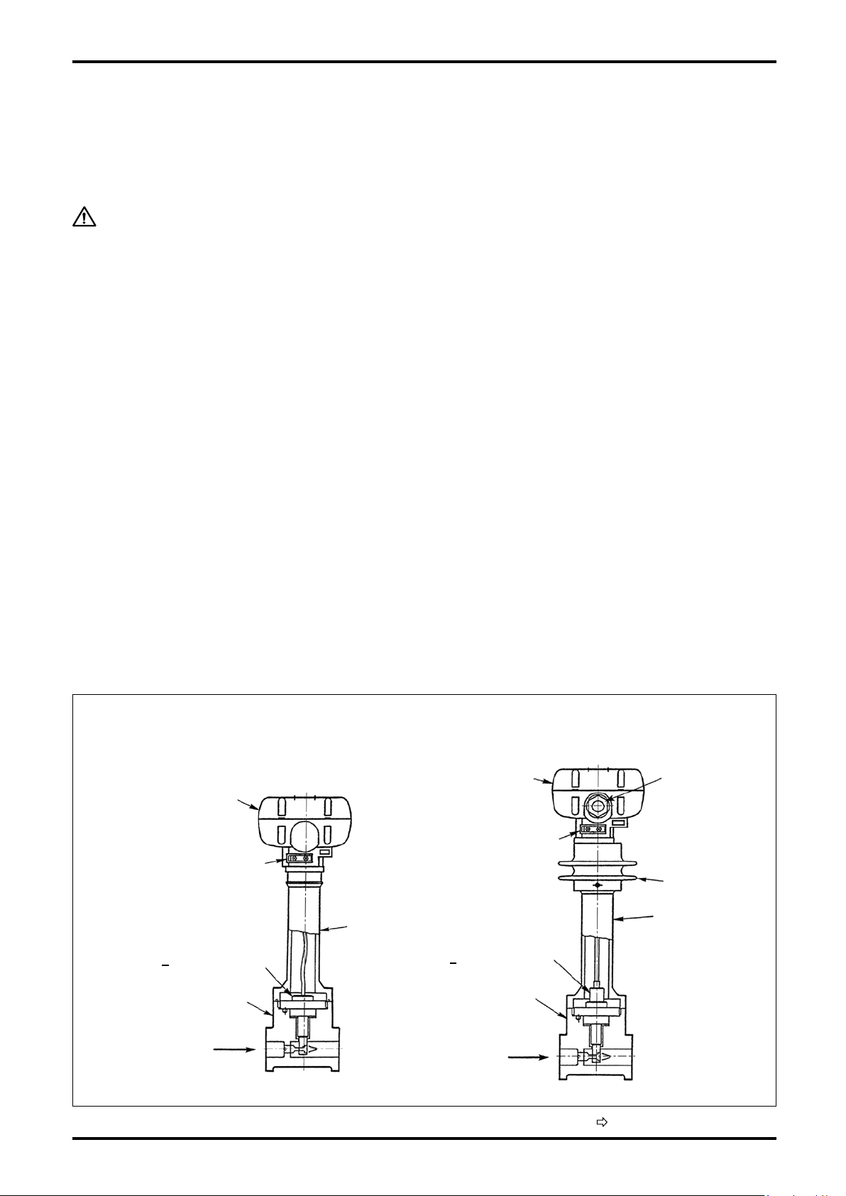
4.1 Part Names
• Standard Type
(operating temp. -10 to +80°C)
(4) Preamplier
(5) Preamp Disconnect
Lever
(3) Adapter
(2) Sensor
Probe
(vortex sensor)
[
(1) Meter Body
Flow Direction
• High-temp. Type
(operating temp. -10 to +200°C)
(4) Preamplier
(5) Preamp Disconnect
Lever
(2) Sensor
Probe
(vortex sensor)
[
(1) Meter Body
Flow Direction
Signal Cable
(one meter long
furnished)
Radiator Fins
(3) Adapter
Fig. 4.1 Part Names
(Continued on next page.)
5
D-555-3-E
(Part names in Fig. 4.1)
(1) Meter Body:
Consists of a measuring pipe and a vortex shedding object (bluff body). As the process uid ows, von
Karman vortices form and shed behind the bluff body.
(2) Sensor (vortex detector):
Contains a piezoelectric sensor. The piezoelectric element oscillating with Karman vortices changes the
occurrences of vortices into changes in electric charge.
(3) Adapter:
Connects the meter body with the preamplier. It also serves as a sensor protector and radiator ns.
(4) Preamplier:
Transforms changes in electric charge generated from the sensor into an output signal representing the
owrate and shows the instantaneous owrate and total ow on an 8-digit LCD display.
You can select alarm outputs, a pulse or analog output for a remotely located receiving instrument.
The preamplier display is rotatable: it can be oriented to any position for maximum readability.
(5) Preamplier disconnect lever:
Separates the preamplier with a pull of this lever.
CAUTION: To eliminate the possibility of poor electrical contact and other
undesirable trouble, good practice is to keep your hands off this lever
except for maintenance.
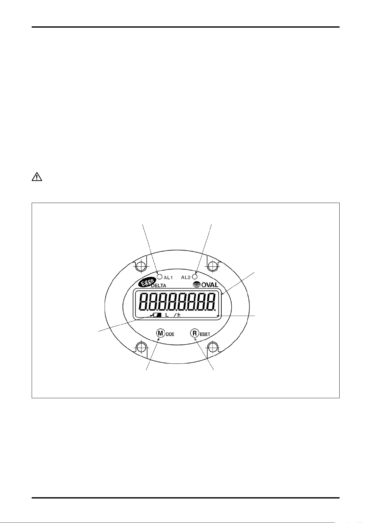
(8) Alarm 1 Indicator LED (8) Alarm 2 Indicator LED
Low Battery Alarm
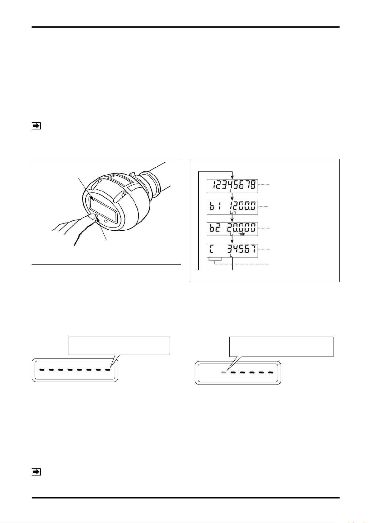
(6) "MODE" Switch (7) "RESET" Switch
Fig. 4.2 Display
Display (8-digit LCD)
LCD Units of Registration
{L, kL, m3, g, kg, t,
/h, ○/min (normal)}
○
(See Paragraph 4 .2.3 on
page 8.)
(Part names in Fig. 4.2)
(6) "MODE" Switch:
By applying the selector magnet to the eld labeled "MODE", the display scrolls through available menu
items of variables in the order "Accumulated total ow" → "Hourly instantaneous owrate" → "Per-minute
instantaneous owrate" → "Resettable total ow".
(7) "RESET" Switch:
Applying the selector magnet to the eld labeled "RESET" resets the "Resettable total ow" to zero.
(8) Alarm indicator LEDs (ow switch feature):
Battery powered model is not provided with alarm indicator LEDs (AL1 and AL2).
6
D-555-3-E
Hourly instant.
flowrate : L/h
Accumulated total flow
An Example of Display
Per-min. instant.
flowrate : L/min
Resettable total flow
Mode symbol
Indicat es a coun tdown before
"prolon ged depre ssion" processing
takes p lace.
Indicat es that t he switch is turned
"ON".
4.2 Display Functions and Operation
In normal operation, four variable-accumulated total flow, hourly instantaneous flowrate, per-minute
instantaneous owrate, and resettable total ow-can be shown along with the units of measurement.
4.2.1 Display Menu Selection
By depressing the "MODE" switch on the display to turn it on, the display scrolls through available menus items
as shown in Fig. 4.3. The display changes from one menu item to another upon "MODE" switch depression,
scrolling as shown in Fig. 4.4.
NOTE: 1. The display scrolls on release of the nger holding the switch.
2. It is expressed in this manual that the switch remains turned "ON" while pressing the switch; on
release, it turns "OFF".
8-digit LCD Display
4.2.2 About the Displayed Messages during Operation
(1) Ordinary operation
"MODE" switch is turned "ON"
(selector magnet held close to it.)
8 bars appear.
⇒
Immediately turning "OFF" (selector magnet
⇒
the window to the next one.
NOTE: While RESET switch is in a valid mode (resettable total mode, etc.), the same message as stated
“MODE” Switch
Fig.4.3
Fig.4.4
(2) Prolonged operation
Held turned ON without turning "OFF" immediately
by removing the ngers.
Bars begin to disappear from the leftmost one.
⇒
Holding turned ON until the last bar disappears
⇒
results in "prolonged depression" processing (*)
to takes place.
(Turning OFF before the last bar disppears
results in the same behavior as in (1) to take
place.)
* Prolonged operation: An operation required
for Normal mode ⇔ Parameter review mode
above appears in response to RESET switch operation. (There is no distinction between ordinary
depression and prolonged depression.)
selection, nalizing the parameter setting, etc.
7
D-555-3-E
L
Battery mark
h
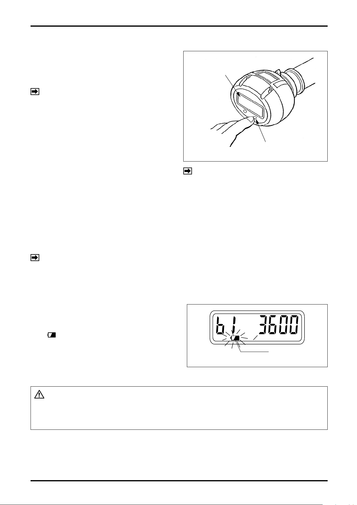
4.2.3 Total Counter Reset
When "RESET" switch is turned "ON" while the
display shows "Resettable total ow" (mode symbol
"C"), the total reading is automatically reset to zero
(Fig. 4.5).
NOTE: It is only resettable while "resettable total
ow" is shown.
8-digit LCD Display
"RESET" Switch
Fig.4.5
NOTE: Reset timing remains the same as that
of display menu selection (see Note 1 in
Paragraph 4.2.2).
4.2.4 About the Measurement Units
The following units of measurement can be displayed. A owrate unit that matches the customer specication
(chosen from the available units below) is set up before the product leaves the factory.
L, kL, m3, g, kg, t, /h, /min., (normal), and none
To change the currently indicated measurement unit, see Chapter 8 and Section 8.2 on pages 16 and 18.
NOTE: A change in the indicated measurement unit by no means affects the indicated owrate.
4.2.5 Low Battery Alarm Indication
Produ ct wit h " no out put (battery-operated)" is
driven by the built-in battery. If the battery capacity
becomes low requiring battery replacement, battery
mark ( ) lights at the bottom of the front display.
When this indicator goes on, you are requested to
replace the battery within a week. (For the method of
replacement, refer to page 29.)
Fig.4.6
CAUTION: Regarding "All lights on indication" (see page 24) in Parameter Check
Mode, all the segments of the display go on with lit battery mark.
However, the lighting of battery mark does not show the end of
battery life.
8
D-555-3-E
8D
Flow
12D
Flow
15D min.
Flow
23D min.
Flow
25D min.
Flow
40D min.
Flow
15D min.
Flow
Fully open
50D min.
Flow
Partially open
5. PIPING INSTRUCTIONS
For general considerations to be observed, see JIS Z 8766, "Flowrate Measurement Methods with Vortex
Flowmeters".
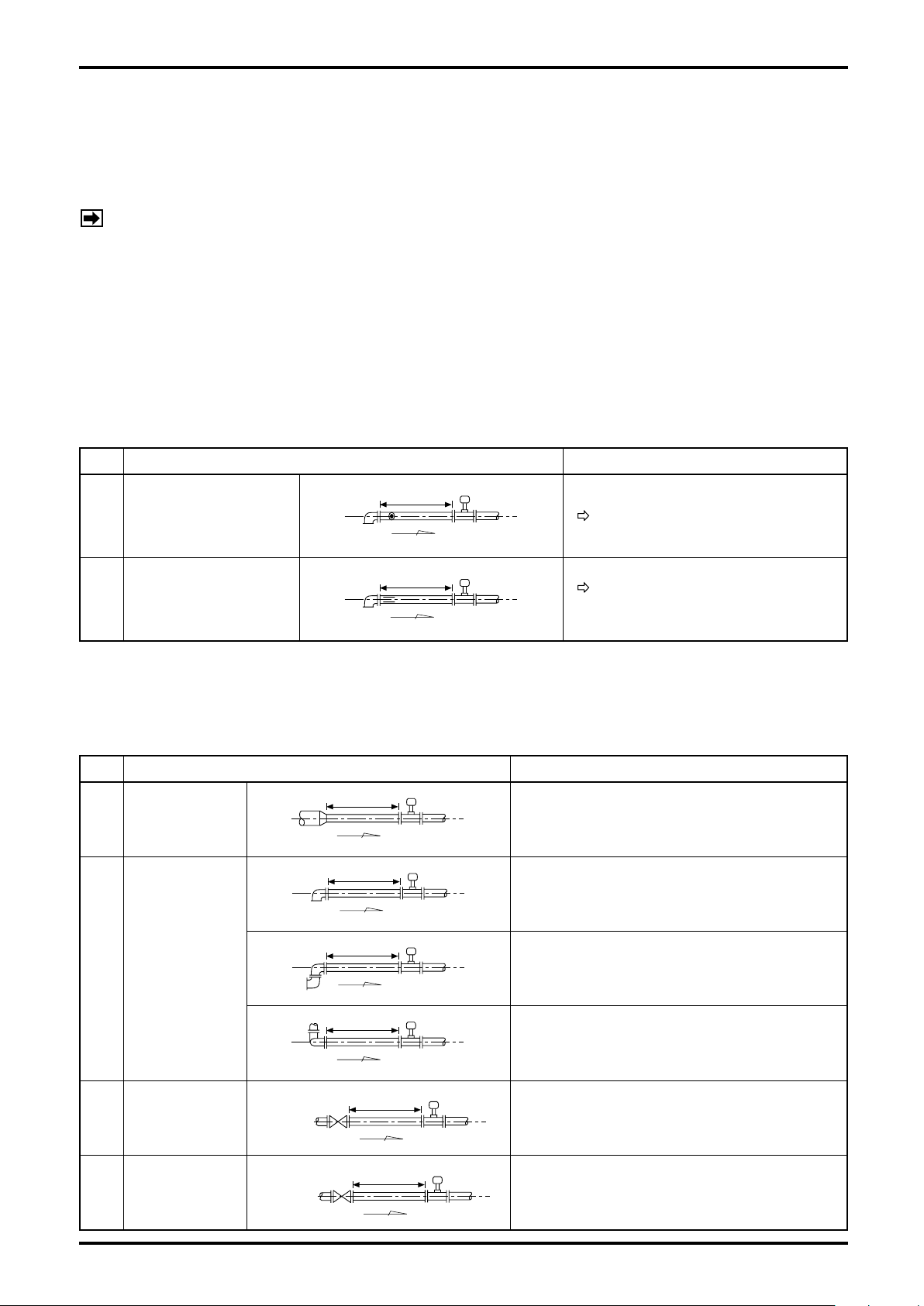
5.1 Standard Piping Conditions
NOTE: A downstream straight pipe 5D or longer is required.
It is generally required that the ow pattern of a material moving into an inferential type meter be as uniform
as possible for precise metering. Accordingly, proper ow straightening measures must be taken when the
application engineer considers installation of a vortex owmeter. In applications where OVAL straightening
devices (ow straightener, Honey Vane, and downstream pipe) are used, a straight pipe section is not required
unless otherwise specied. But if he plans to solve the ow pattern problem with a straight pipe section alone,
secure the length of a straight pipe conforming to the ISO standards given in Table 5.1 below, using a Sch. 40
pipe.
(1) OVAL flow straightener combined with downstream pipe (25mm and up in nom. dia.)
D = Nom. Dia.
No. Arrangement Remarks
1 Honey Vane L
2 Flow Straightener
See Fig. 5.1 on page 10.
See page 37 for face-to-face
dimension.
(2) Straight pipe alone without flow straightener
To match the meter diameter, use a Sch, 40 pipe for the straight pipe.
Table 5.1 Straight Pipe Lengths Recommended by ISO-5167
No. Arrangement Remarks
1 Reducer
A concentric reducer is upstream of meter.
An elbow is upstream of meter.
2 Elbow
Two elbows are horizontally upstream of
meter.
D = Nom. Dia.
Gate Valve
3
Fully Open
Gate Valve,
4
Partially Open
Two elbows are vertically upstream of meter.
A full-open gate valve is upstream of meter.
A partially open gate valve, a narrow orice,
or something that considerably disturbs the
ow pattern is upstream of meter.
9
D-555-3-E
Honey Vane "S" Honey Vane "L"
t
φD
L
t
FLOW
Honey Vane S
Flowmeter
Short pipe
Min.8D
Honey Vane S
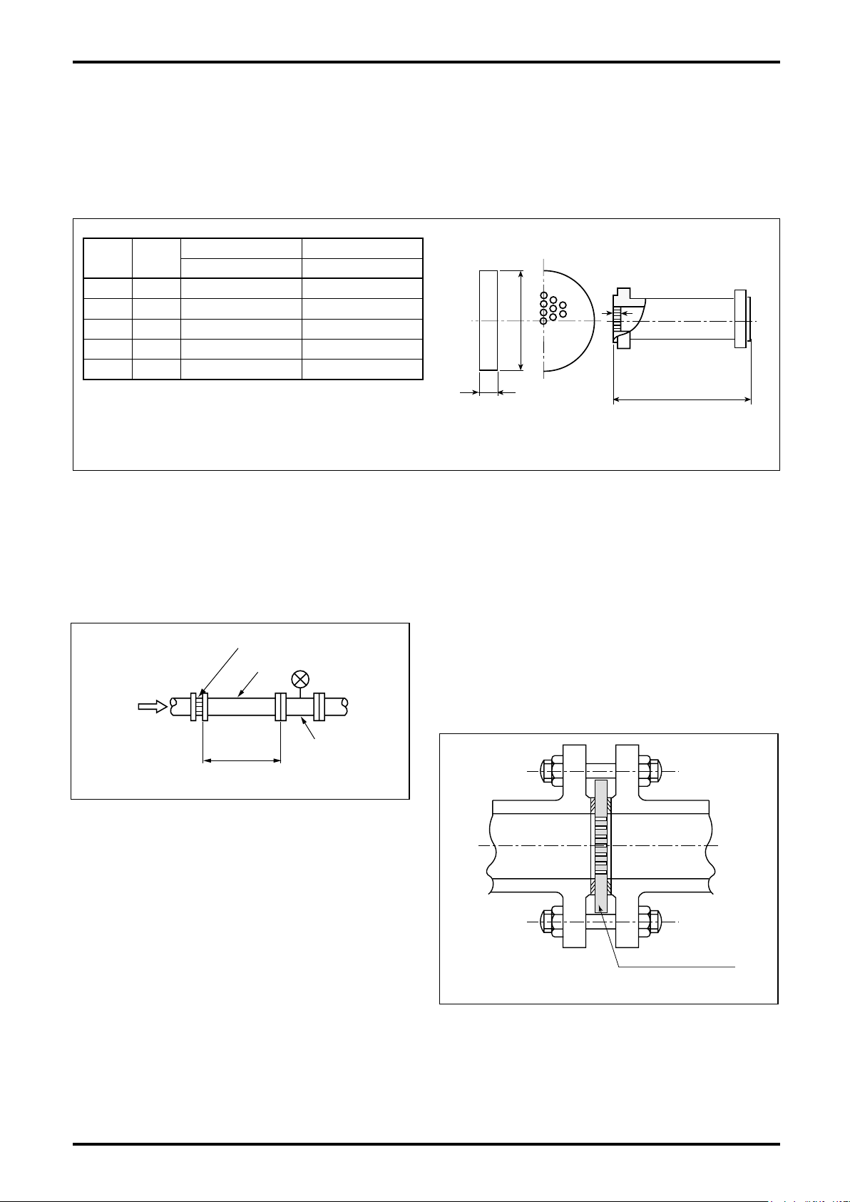
(3) Space Saving Arrangement
If required straight pipe space is not obtainable upstream of the vortex owmeter due to existing restrictions on
installation location, the OVAL Honey Vane S combined with a short pipe may be used to get around the space
problem.
• Honey Vane Outline Dimensions
Unit in mm
Nom
Dia.
φ
25
40 89 5.4 320
50 104 6.9 400
80 134 10.2 640
100 159 13.3
* Dimensions with JIS 10K
Honey Vane "S" Honey Vane "L"
D*
t L
74 3.5 200
800
Fig.5.1
(4) Installation
Required straight pipe length
①
Provid e at least 8D be tween the flowmeter and
Honey Vane S where D is the straight pipe diameter.
Fig.5.2
Installation (wafer type)
②
Sandwich between anges (see gure below).
NOTE: Customer to furnish connecting bolts, nuts
and gasket for the pipe.
Regarding the bolts and nuts used for
connecting JPI ange, adopt unied screw
threads. If you want to use metric screw
threads, contact OVAL.
10
Fig.5.3
D-555-3-E
Flowmeter
Flow
Direction
Pressure Gage Tap
Thermometer Tap
2 to 7D
φ 6
D = Nominal Dia.
5.2 Pipes to be Used
Nominal thickness Sch. 40 pipes should be used for upstream and downstream pipes of this meter.
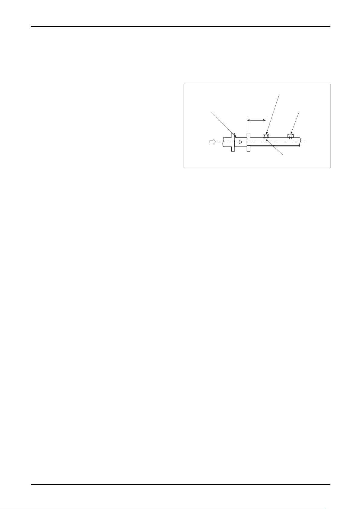
5.3 Location of Pressure Gauge and Thermometer Taps
Taps for the pressure gauge and/or thermometer,
if desired, should be located downstream of the
owmeter as illustrated in Fig. 5.4.
Fig.5.4
5.4 Pulsations
Compressors, Roots blowers and other ripple pressure generating sources could adversely affect meter
performance. Minimize pulsating pressures by referring to the following formula:
N < 22ρ V2 (Pa)
where N : Pulsation pressure (Pa)
: Density (kg/m3)
ρ
V : Minimum velocity (m/s)
If pulsation pressure is excessive, the following measures should be taken into consideration:
(1) Locate the source of pulsation downstream of the meter or locate it as far from the meter as possible.
(2) Provide a pulsation attenuator, such as a chamber or pulsation snapper.
(3) Shut off valves upstream and downstream of the meter when fluid flow is interrupted (as a precaution
against erratic signal generation at zero ow).
5.5 Prevention of Cavitation (liquid service)
To prevent cavitation, line pressure should be maintained above the level calculated by the following formula:
P ≧ 2.60
P + 1.25P
∆
where ∆P : Pressure loss (MPa)
≒
1.2
P0 : Steam pressure of liquid (MPa abs.)
ρ : Density (kg/m3)
V : Flow velocity (m/s)
(MPa abs.)
0
V2 ×10
ρ
−6
11
D-555-3-E
P1
P2
FLOW
P1
P2
FLOW
VALVE
METER
GAGE
GAGE
DOWNSTREAM
VALVE
METER
UPSTREAM
VALVE
VALVE IN BYPASS LINE
FLOW
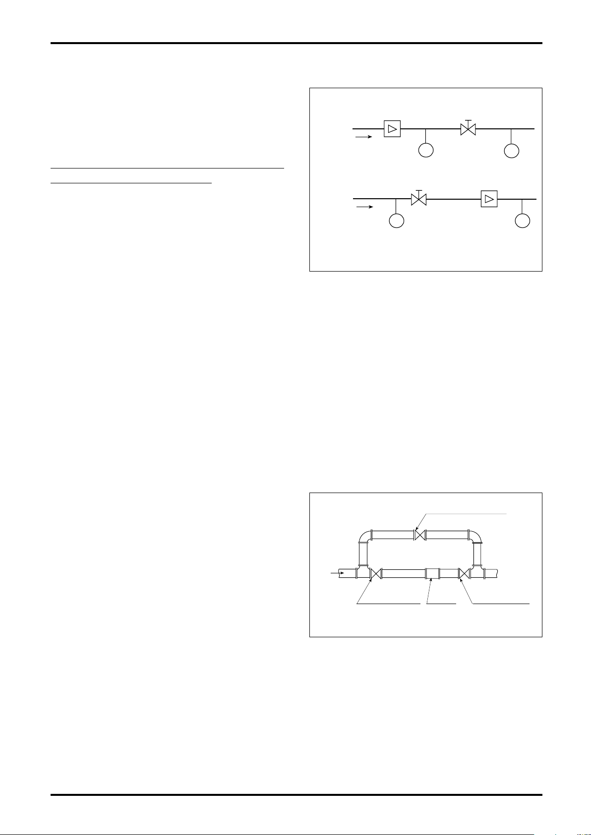
5.6 Prevention of Excessive Flowrate
To ensure long meter life, transient owrates should
be held below 1.6 times the me ter 's max imu m
"A"
ratin g . Sh o wn below a re typi c a l ex amples i n
steam measurement where excessive ow is often
encountered:
Examples where meter's m axi mum rating is
exceeded on a momentarily basis
"B"
In stea m m easu rem ent, whe n P1 > P2 , quickl y
opening the valve will result in a uid ow at a rate
de pen dent on the line resistance (ma inly valve
port position in "A" or meter resistance in "B").
The resultant rate of incoming flow is the sum of
downstream pipeline volume and consumption, but
Fig.5.5
if pressure differential across the valve is great, the uid velocity will easily reach the sonic speed, momentarily
well in excess of meter's maximum rating. (Such phenomenon is often experienced at system startup or in
batch operation.)
5.7 Prevention of Slug Flow
This meter can measure both gases and liquids, but slug ows (where gases exist in the process liquid) will
produce a loss of meter accuracy.
5.8 Partially Filled Pipe
When making a liquid measurement, ensure that the piping remains full of the process liquid. Installation in
locations where it is difcult to keep the piping lled with the process liquid, or where bubbles tend to collect
should be avoided.
5.9 Bypass Line
For maintenance and servicing purposes, it is a good
practice to provide a bypass line. Valves upstream
and downstream of the meter should be of a design
which will not disturb uid ow pattern, such as ball
valves (full bore type), in this arrangement (see Fig.
5.6).
For general considerations to be observed, refer
to JIS Z 8766, "Flowrate Measurement Methods
with Vortex Shedding Flowmeters".
Fig.5.6
12
 Loading...