

Page 1
Ins. No.
L-737-3-E
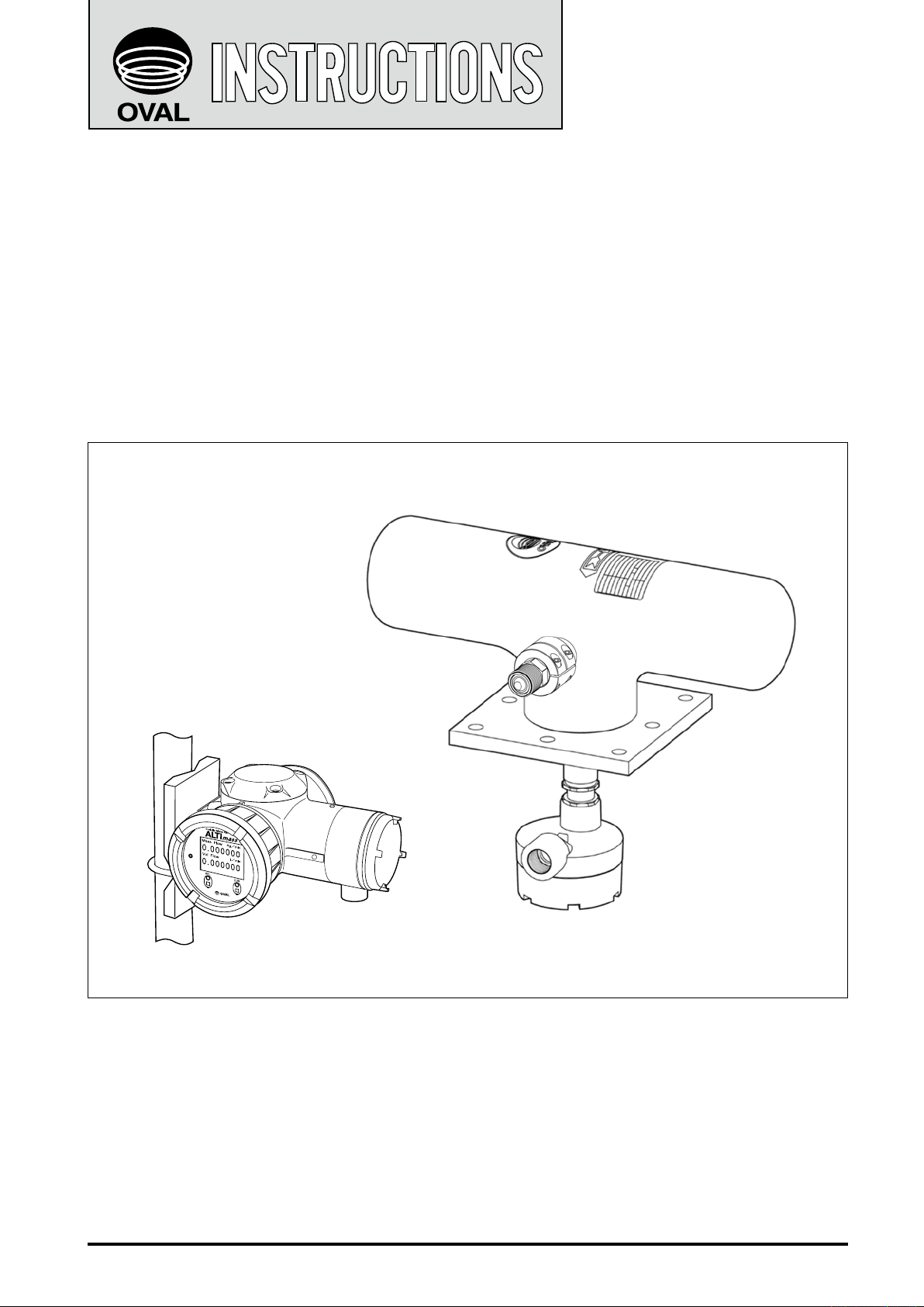
Extra-high pressure service Coriolis flowmeter
ALTI
mass
Sensor Unit MODEL : CA004
Transmitter MODEL : PA0K
Every OVAL product is fabricated, tested, and inspected under stringent quality control before it leaves our
factory.
To derive maximum benefit from this product, we recommend you to be well familiar with the information and
instructions given in this manual before you place it in service, and keep this manual handy for quick reference.
1
Page 2

L-737-3-E
CONTENTS
1. BEFORE YOU BEGIN ............................................................................................ 5
1.1 Confirming the Tag Information ...................................................................................................5
1.2 Transportation Considerations ....................................................................................................6
1.3 Storage Considerations ...............................................................................................................6
1.4 Operating Conditions ..................................................................................................................6
1.5 Precautions at Installation ...........................................................................................................6
1.6 Precautions for power-on ............................................................................................................6
1.7 Returning Equipment ...................................................................................................................6
2. GENERAL AND FEATURES ................................................................................. 7
2.1 General ........................................................................................................................................7
2.2 Features ......................................................................................................................................7
3. SPECIFICATIONS AND PERFORMANCE ............................................................. 7
3.1 Sensor Unit ..................................................................................................................................7
3.1.1 General Specifications ............................................................................................................7
3.1.2 General Performance .............................................................................................................8
3.1.3 Pressure Loss ........................................................................................................................ 8
3.2 Transmitter General Specifications .............................................................................................9
4. PART NAMES AND OUTLINE DIMENSIONS .................................................... 10
5. INSTALLATION .................................................................................................... 12
5.1 Considerations at Installation .................................................................................................... 12
5.2 Physical Orientation .................................................................................................................. 12
5.3 Piping Instructions ..................................................................................................................... 12
5.3.1 Standard Piping Conditions ................................................................................................. 12
5.3.2 Influences of Vibration and Pulsations ................................................................................ 13
5.3.3 Prevention of Cavitation ...................................................................................................... 13
5.3.4 Prevention of Excessive Flow Rate ...................................................................................... 13
5.3.5 Keeping the Sensor Unit Completely Filled ......................................................................... 13
5.3.6 Bypass Line ........................................................................................................................ 13
5.4 Installation Instructions ............................................................................................................. 14
5.5 Sensor Unit-to-Tubing Connection Guidelines .......................................................................... 14
5.5.1 Machining the Female Connector (for reference purpose) .................................................14
5.5.2 Connection Procedure ........................................................................................................ 15
5.6 Securing the Sensor Unit and Tubing Clamps .......................................................................... 16
5.7 Heat Insulation Work ................................................................................................................. 17
5.8 Separately Mounted Transmitter Installation ............................................................................. 18
5.9 How to Change Transmitter Orientation .................................................................................... 19
5.10 How to Change Transmitter Display Orientation .....................................................................20
6. WIRING INSTRUCTIONS ..................................................................................... 22
6.1 Terminal Box Cover Removal .................................................................................................... 22
6.2 Wiring Connections ....................................................................................................................22
6.2.1 Cable lead-in ....................................................................................................................... 22
6.2.2 Power and output signal connections (both integrally and separately mounted models) .... 23
6.2.3 Connections between separately mounted sensor unit and transmitter .............................. 24
6.3 Power Supply Lines and Ground Terminal ................................................................................. 24
6.4 Analog Output Wiring ................................................................................................................. 24
6.5 Pulse Output Wiring ...................................................................................................................24
6.6 Status Output Wiring ..................................................................................................................25
6.7 Status Input Wiring ..................................................................................................................... 25
6.8 Communication Line Wiring (option) ..........................................................................................26
6.9 Recommended Cables for Use in Output Signals .................................................................... 26
2
Page 3

L-737-3-E
6.10 Terminal Identification of Remotely Mounted Transmitter ....................................................... 26
6.11 Wiring Diagram ........................................................................................................................ 27
6.11.1 Transmitter power and output signal wiring.........................................................................27
7. REMOTELY MOUNTED TRANSMITTER AND SENSOR UNIT WIRING ........... 28
8. OPERATION ......................................................................................................... 29
8.1 Flushing the Piping Assembly ....................................................................................................29
8.2 Confirming the Sensor Unit for Correct Installation ...................................................................29
8.3 Leak Check ................................................................................................................................29
8.4 Supplying the Power ..................................................................................................................29
8.5 Measurement Line Startup ......................................................................................................... 29
8.6 Warm-up ................................................................................................................................... 29
8.7 Zeroing Procedure .....................................................................................................................29
8.8 Readying for Operation ..............................................................................................................29
9. DESCRIPTION OF INCORPORATED FUNCTIONS ............................................ 30
9.1 Display ........................................................................................................................................30
9.1.1 Description of display ........................................................................................................... 30
9.1.2 Switch operation ................................................................................................................... 31
9.1.3 Viewing the variables ........................................................................................................... 32
9.2 Viewing the Parameters and Description ...................................................................................34
9.2.1 Viewing the setup menu .......................................................................................................35
9.2.2 Transition chart of view (1) ...................................................................................................36
9.2.3 Transition chart of view (2) ...................................................................................................38
9.2.4 Transition chart of view (3) ...................................................................................................40
9.2.5 Transition chart of view (4) ...................................................................................................42
9.2.6 Transition chart of view (5) ...................................................................................................44
9.2.7 Transition chart of view (6) ...................................................................................................46
9.3 Parameter Value Entry ............................................................................................................... 48
9.4 Parameter Selection ...................................................................................................................49
9.5 Password Function .....................................................................................................................50
9.5.1 Password function setup ......................................................................................................50
9.6 Self-diagnostic Capabilities ........................................................................................................ 51
9.6.1 Probe check .........................................................................................................................51
9.6.2 Drive coil check ....................................................................................................................52
9.6.3 Transmitter check ................................................................................................................. 53
9.6.4 Pipeline oscillation check (at zero flow) ................................................................................54
9.6.5 Pipeline oscillation check (normal flow) ...............................................................................55
9.7 Simulated Signal Input/Output Capabilities ................................................................................ 56
9.7.1 Analog output ....................................................................................................................... 56
9.7.2 Pulse output ......................................................................................................................... 57
9.7.3 Status output.........................................................................................................................58
9.7.4 Status input ...........................................................................................................................59
9.8 Zeroing Function ........................................................................................................................60
9.8.1 Through LCD display switches ............................................................................................. 60
9.8.2 Through status input signal .................................................................................................. 61
9.8.3 Through Link Top communication ........................................................................................ 61
9.9 Analog Trim Function .................................................................................................................62
9.10 Reset Function ..........................................................................................................................63
9.11 View Variables Screen Setup ...................................................................................................64
9.12 Pulse Output Function ..............................................................................................................65
9.12.1 Pulse output 1 .....................................................................................................................65
9.12.2 Pulse output 2 .....................................................................................................................65
9.12.3 Bidirectional pulse output ...................................................................................................66
3
Page 4

L-737-3-E
9.12.4 Double pulse input ..............................................................................................................67
9.13 Analog Output Function ............................................................................................................68
9.14 Status Output Function .............................................................................................................69
9.14.1 Status output (Error Status).................................................................................................69
9.14.2 Bidirectional flow direction output (Bi Direction) .................................................................69
9.14.3 H/L alarm output (H/L Alarm) ............................................................................................. 70
9.14.4 No assignment (No Function) ............................................................................................70
9.14.5 No assignment (No Function) ............................................................................................70
9.15 Status Input Function ................................................................................................................ 71
9.15.1 Pulse/analog output fixed at 0% (0% Sig Lock) ................................................................. 71
9.15.2 Zero adjustment (Auto Zero) .............................................................................................. 71
9.15.3 Totalizer 1 and totalizer 2 reset (Reset Total 1 and 2) ........................................................ 71
9.15.4 Totalizer 1 reset (Reset Total 1) .........................................................................................72
9.15.5 Totalizer 2 reset (Reset Total 2) .........................................................................................72
9.16 High/Low Alarms Function ........................................................................................................ 73
9.17 Gas Mixed Flow Alarm ..............................................................................................................75
9.18 Setup Units List .........................................................................................................................77
10. MAINTENANCE .................................................................................................. 78
10.1 Error Messages ........................................................................................................................78
10.2 List of Status Messages ........................................................................................................... 79
10.3 Replacement Parts ...................................................................................................................80
10.4 Explosionproof specification .................................................................................................... 81
10.5 Precautions on the explosionproof specification ......................................................................82
10.5.1 About the explosionproof ....................................................................................................82
10.5.2 About handling of the flameproof enclosure .....................................................................82
10.5.3 Insulation performance ......................................................................................................84
10.5.4 Earthing terminal ...............................................................................................................84
10.5.5 About dedicated cable (for only separate type) .................................................................84
10.5.6 Maintenance and checking ................................................................................................85
11. EX-INFORMATION .............................................................................................. 86
11.1 Nameplates ............................................................................................................................... 86
11.2 System Block Diagram (Control Drawing) ................................................................................87
11.3 Inductance and Internal Resistance of Sensor Coil .................................................................89
11.4 Regarding FISCO System of FOUNDATION fieldbus and PROFIBUS ................................... 89
11.5 Explosionproof Applicable Temperature (Integrally Mounted Type Only) ................................91
12. ABOUT MARITIME CERTIFICATION ............................................................... 92
13. PRODUCT CODE EXPLANATION ................................................................... 93
■ SHIPPING PARAMETERS ..............................................................................................................94
■ SAFETY STATEMENT ON RETURNED GOODS ..........................................................................96
■ REPAIR REQUEST SHEET .............................................................................................................97
This manual uses the precaution words "NOTE", "CAUTION", and "WARNING" as explained
below:
NOTE: Notes are separated from the general text to bring the user's attention to
important information.
CAUTION: Caution statements inform the user of hazards or unsafe practices which
could result in minor personal injury or product/property damage.
WARNING: Warning statements inform the user of hazards or unsafe practices which
could result in severe personal injury or death.
4
Page 5
L-737-3-E
1. BEFORE YOU BEGIN
Once you receive the product, it should be thoroughly inspected for any sign of damage by rough handling
during transit.
Carefully read the precautionary notes on handling in this section.
If you have something to inquire, contact the nearest OVAL sales/service office in your
district.
1.1 Confirming the Tag Information
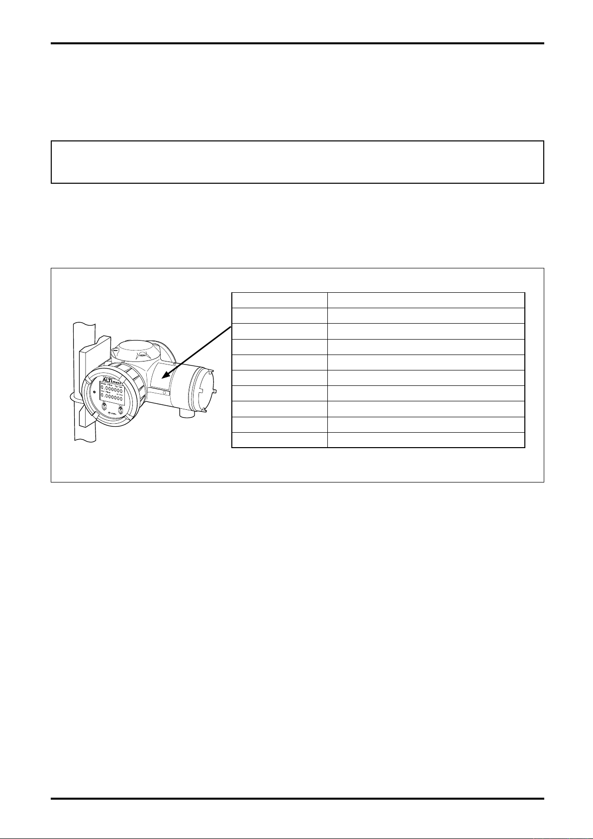
Product code and major ratings appear on the meter nameplate. Make sure that the product you received
complies with the specifications in your order.
Item Description
MODEL Product model
SERIAL NO. Serial number
MAX. PRESS. Max. operating pressure
MAX. TEMP. Max. operating temperature
FLOW RANGE Flow range
POWER Power
TAG NO. Instrument No. (only when specified)
BORE Nominal size
DATE Date of manufacture
Fig. 1.1 Product Tag and Location
NOTE: When you inquire, please provide information such as product name, model number, serial
number, ratings, etc.
5
Page 6

L-737-3-E
1.2 Transportation Considerations
(1) The OVAL flowmeter can best be transported to the installation site in the shipping container used for
transit from the factory.
(2) Avoid impact shocks during transit.
1.3 Storage Considerations
If the meter is to be stored for extended periods of time upon receipt before installation, unexpected problems
could arise. If such is the case, the following considerations should be taken:
(1) The flowmeter can best be stored in the original package used for transit from the factory.
(2) The place of storage should meet the following requirements:
Free from rain and water
Free from vibration and impact shock
Storage/shipping conditions
Temperature:20±15℃ Relative humidity:65±20% Barometric pressure:500 to 1060hPa
1.4 Operating Conditions
In order to maintain the designed metering accuracy and long service life, it is essential that the ratings, such
as the flow rate, pressure, and temperature be kept within the specified limits. These operating conditions are
stated in Sections "3. SPECIFICATIONS AND PERFORMANCE" and "13. PRODUCT CODE EXPLANATION" of
this manual. Make sure to fully understand them before placing the meter in service.
◦ If the process fluid is corrosive, the meter materials must be reviewed for compatibility.
◦ Cleanse the interior of flow tube thoroughly after use for measuring fluids that tend to deposit
solids. If solid deposits adhere to flow tube, it can affect the meter accuracy.
◦ If you need to change operating conditions, consult OVAL.
◦ Some gasmixtures that are not homogeneous cannot be measured. Consult OVAL for applicability.
1.5 Precautions at Installation
CAUTION:
To ensure accurate and stable measurement, the Coriolis flowmeter should be
installed in a location where piping vibration will not exceed 0.3G.
1.6 Precautions for power-on
Be sure to close the display lid and the terminal lid of the transmitter before turning on the power. The
explosionproof enclosure must be ensured (with the requirements stated in section 10.5 satisfied) before use.
To ensure the stable measuring condition, allow 20 minutes of warm-up period. "WARM UP 20" will be
displayed for 20 minutes after powering-on. The number indicates remaining warm-up period (min.).
1.7 Returning Equipment
If the meter must be returned to OVAL for any reason, follow these steps to ensure the most efficient
processing.
(1) Clean the unit and flush out the flow tube and pack the sensor unit carefully. Fully document the fluid.
Inadequate information will delay handling of the meter. (⇨ Fill in the forms prepared on pages 96 and 97.)
(2) Enclose complete information about the contents being returned including model and serial numbers,
the reason for return, return address, and full documentation of the type of fluid in writing.
(3) Pack the equipment carefully, using the original packing if possible.
(4) Return the complete flowmeter, including, for instance, the transmitter with all associated components.
Remove the conduit connections and all other parts not originally shipped with the meter (for
example, wiring connections).
Be sure to completely remove any foreign matter inside the sensor unit . Because the sensor
unit cannot be disassembled, OVAL will not be able to clean residue inside the tube and service
your meter.
6
Page 7

L-737-3-E
2. GENERAL AND FEATURES
2.1 General
Our concentrated effort in developing true state-of-the-art measuring devices and specialized manufacturing
experience in Cor iolis technology has resulted in this ex tra-high pressure ser vice Coriolis flowmeter
characterized by outstanding performance, ease of use, and increased safety.
It consists essentially of a sensor unit and a transmitter (PA0K). Equipped with a high performance transmitter
having a self-diagnosis function, large screen display, and the capability to change settings on-site by
touchscreen, This Coriolis flowmeter can directly measure mass flow rate with high accuracy.
2.2 Features
(1) High accuracy and high sensitivity.
(2) Accepts both liquid and gas. Measures a wide flow range accurately.
(3) Measures temperature besides mass flow rate.
(4) Branchless flow path design offers ease of cleaning.
(5) No welded point in the wetted parts − a truly dependable design suitable for high pressure gas
measurement.
(6) The wetted parts are made of XM-19 which is resistant to hydrogen embrittlement. Therefore this model is
especially suitable for the flow measurement of high-pressure hydrogen.
(7) The meter casing has a high mechanical rigidity for ease of use, reducing space requirements, and
increasing process safety.
(8) Explosionproof design allows for its use in hazardous locations.
3. SPECIFICATIONS AND PERFORMANCE
3.1 Sensor Unit
3.1.1 General Specifications
Item Description
Model CA004
Measuring Tube O.D. 9/16
Materials
Connector connection
Acceptable fluids Liquid and gas ※1
Density range 0 to 2.0 g/mL
Temperature range
(Structural rating)
Max. operating pressure 120MPa (at 93℃ )
Flow direction Forward and reverse, both available
Explosionproof configuration (See the topic under 10.4 Explosionproof specification)
Weight
(Terminal box and mtg. base incl.)
Wetted parts TPXM-19 UNS S20910 SA-312
Housing SUS304
High-press. cone & thread connection, size 9/16 562C
(male thd. 1•1/8-12UNF)
−40 to +130℃
Approx. 21kg
NOTES
※1: For hydrogen gas at 20℃, the required operating pressure [MPa] can be calculated as
measuring flow rate [kg/h] times 0.19. (e.g. approx. 22.8MPa or more when 120 kg/h)
For the precise required operating pressure, contact OVAL.
※: For the High Pressure Gas Safety Act applicable model, contact OVAL.
7
Page 8

L-737-3-E
ΔP
2
=C× ×
1
d
μ
2
μ
1
d
C
ΔP=
(MP a )
0.00001
0.1 1 10 100 1000
0.0001
0.001
0.01
0.1
1
10
100
1000mPa・s
100mPa・s
10mPa・s
1mPa・s
0.01mPa・s
3.1.2 General Performance
Item Description
Model CA004
Max. allowable rate 300kg/h
Flow rate
Pressure loss
(Reference)
Max. service rate
Min. setting rate 6kg/h
Guaranteed min. rate 2.4kg/h
Accuracy
Repeatability
9.6kg/h or above to 300kg/h or less ±0.5% of RD
9.6kg/h or above to 300kg/h or less ±0.25% of RD
Less than 9.6kg/h ±0.05% of max. allowable rate
Less than 9.6kg/h ±0.025% of max. flow rate
Analog output accuracy ±0.1% of FS added to each accuracy
Water: at Max. allowable
rate
120kg/h
1.15MPa
CAUTION:
1. Since the casing of sensor unit is not pressure resistant, the withstanding pressure rating
of the casing is not indicated. To afford adequate protection to personnel, an Rc 1/4 boss is
provided in an area shown in Fig. 4.1; Use customer's discretion in providing a rupture disc,
pressure switch, etc. Rupture disc pressure rating and pressure switch setting is 7 MPa (G).
A precaution to remember: removing the Rc 1/4 plug with the boss pointing downward may
result in the leakage of inert argon gas. In this case, refill with an inert gas, such as argon.
For further details of treatment, consult OVAL.
2. Density measurement and volumetric flowmetering are unacceptable.
3.1.3 Pressure Loss
◎How to determine pressure loss (liquids only)
(1) Find the pressure loss coefficient C from the flow rate (kg/h) and viscosity of parameter (mPa・s). Dividing this
value C by specific gravity d (1 for water) gives the pressure loss, thus
(2) For high-viscosity liquids not shown in the graph, calculate the pressure loss by using the following equation:
where ΔP2 : Pressure loss of high-viscosity liquid (MPa)
μ2 : Viscosity of high-viscosity liquid (mPa・s)
d : Specific gravity of high-viscosity liquid (1 for water)
μ1 : Maximum viscosity shown in the graph (mPa・s)
C : Pressure loss coefficient found from the maximum viscosity curve at a given flow rate (kg/h)
(3) For pressure loss of gases, consult OVAL.
CA004
8
Pressure loss coeff., C
Flow rate (kg/h)
Fig. 3.1
Page 9

3.2 Transmitter general specifications
Item Description
Model PA0K
Power supply
Power consumption Max. 15W
Ambient temperature - 40 to +55℃ ( ※ 1)
Transmission length (separate type)
Applicable EU directive
Applicable EN standards
Explosionproof configuration
Maritime certification DNV GL (Refer to section 12)
Dusttight, waterproof configuration IP66 / 67
Transmitter configuration Integral or separately mounted
Finish Sensor: Munsell 10B8/4, Covers (front and rear): 2.5PB4/10
Display
Weight Integrally mounted model 3.6kg approx., Separately mounted model 5.0kg approx.
Communication interface
※ Optional except for HART
Damping (default)
Low flow cutoff (default)
Pulse output ( ※ 5)
Analog output ( ※ 5)
Status output ( ※ 5)
Status input ( ※ 5)
85 to 264VAC 50/60Hz or 20 to 30VDC
(Safety rated 100 to 240VAC 50/60Hz)
Max. 200m (Dedicated cable used) ( ※ 2)
EMC Diective :2014/30/EU
ATEX Diective:94/9/EC
LVD Diective :2014/35/EU
EMC :EN61326-1:2013 ClassA
ATEX:EN60079-0:2012 EN60079-1:2007 EN60079-11:2012
IECEx:IEC60079-0:2011 IEC60079-1:2007-04 IEC60079-11:2011
LVD :EN61010-1:2010
ATEX, IECEx, KCs, CSA, GOST, NEPSI
(See the topic under 10.4 Explosionproof specification)
LCD display provided (128 × 64 dots), backlit (white, orange)
Infrared light sensors: 2, LED: 2 (green, red)
HART (Standard)
Modbus
FOUNDATION
fieldbus
PROFIBUS PA AI block × 4, TOT block × 2
Flow rate 0.8sec, density 4sec, temperature 2.5sec.
Under 0.6% of max. service flow rate
Open drain output (equivalent to open collector output ) [Min. 10V to Max. 30V, 50mADC, ON
resiatance 0.6Ω or less] or
Voltage pulse (Low level: 1.5V max., High level: 13V min. Output impedance: 2.2k Ω )
Setting range: 0.1 to 10000Hz (Max. output 11000Hz)
4 to 20mADC (max. load 600Ω)
Select two outputs from instant flowrate (mass or volume) temperature, and density.
Open drain output (equivalent to open collector output ) [Max. 30V, 50mADC, ON resiatance
0.6Ω or less]
Select one output from error ( ※ 4), flow direction, or high/low alarm (default is error)
Contact-closure input (Form "a" contact) Short: 200 Ω max., Open: 100k Ω min.
Select one output from remote zero, total reset, 0% signal lock, or function off (default is
function off).
HART protocol version 7, Bell202 ( ※ 3)
RS-485 Modbus protocol, Baudrate : 9600bps, 19200bps, 38400bps
RTU or ASCII, Response time : 25 to 50 ms
AI block × 4, IT block × 2, with Link Master function
L-737-3-E
NOTES
※1: Below -20℃, the display loses its visibility due to weakened contrast. Both the display and infrared sensor
may exhibit slow responses below -20℃.
※2: If signal transmission length exceeds the maximum transmission length, consult OVAL.
※3: Of the two analog output systems,only analog output 1 is available for HART communication.
※4: Of error outputs, "zero is in progress" status output can also be set up.
※5: When FOUNDATION fieldbus, PROFIBUS PA is selected as the communication interface, all input and
output signals will be turned off.
※: Denoising parts are embedded in the lines between power source, output, communication, and the chassis.
Lower the applied voltage to the following levels in order to conduct insulation test or withstand voltage test
on these lines.
AC: 200V, DC: 250V
9
Page 10
L-737-3-E
2-Rc1/4 Inert Gas Filler Opening
Normally sealed with Rc1/4 plug
Rupture disk, pressure switch, etc.
may be connected here.
The sections indicated by dashed-dotted line are to be implemented by the user
(With rupture disk for implementing option)
Recommended joint: Swagelok tube joint
Model: SS-810-1-4RT (External thread: 1/4B, External diameter of tube: 1/2B)
43.4
The sections indicated by dashed-dotted line are to be implemented by the user
(With rupture disk for implementing option)
Recommended joint: Swagelok tube joint
Model: SS-810-1-4RT (External thread: 1/4B, External diameter of tube: 1/2B)
43.4
View A−A
View A−A
272
457
A A
115
67
96
4-M6 Hex socket bolt
Tighten M6 bolts of the joint clamp
after fixing the joint connection.
High-press. Cone & Thread
Conn., 9/16 dia. 562C
192
229
φ134
φ115
60
15
64
2-M5 Body GND
8-φ14.5
4-M10 Meter fitting bolt (embedded)
4-M10 Meter fitting bolt (embedded)
2-Rc1/4 Inert Gas Filler Opening
Normally sealed with Rc1/4 plug
Rupture disk, pressure switch, etc.
may be connected here.
127
230
200
160
200
160
200
160
96
96
98
272
4-M6 Hex socket bolt
Tighten M6 bolts of the joint clamp
after fixing the joint connection.
High-press. Cone & Thread
Conn., 9/16 dia. 562C
Conduit
Connection
G3/4
A A
457
192174
φ115
15
φ107
2-M5 Body GND
8-φ14.5
200
160
96
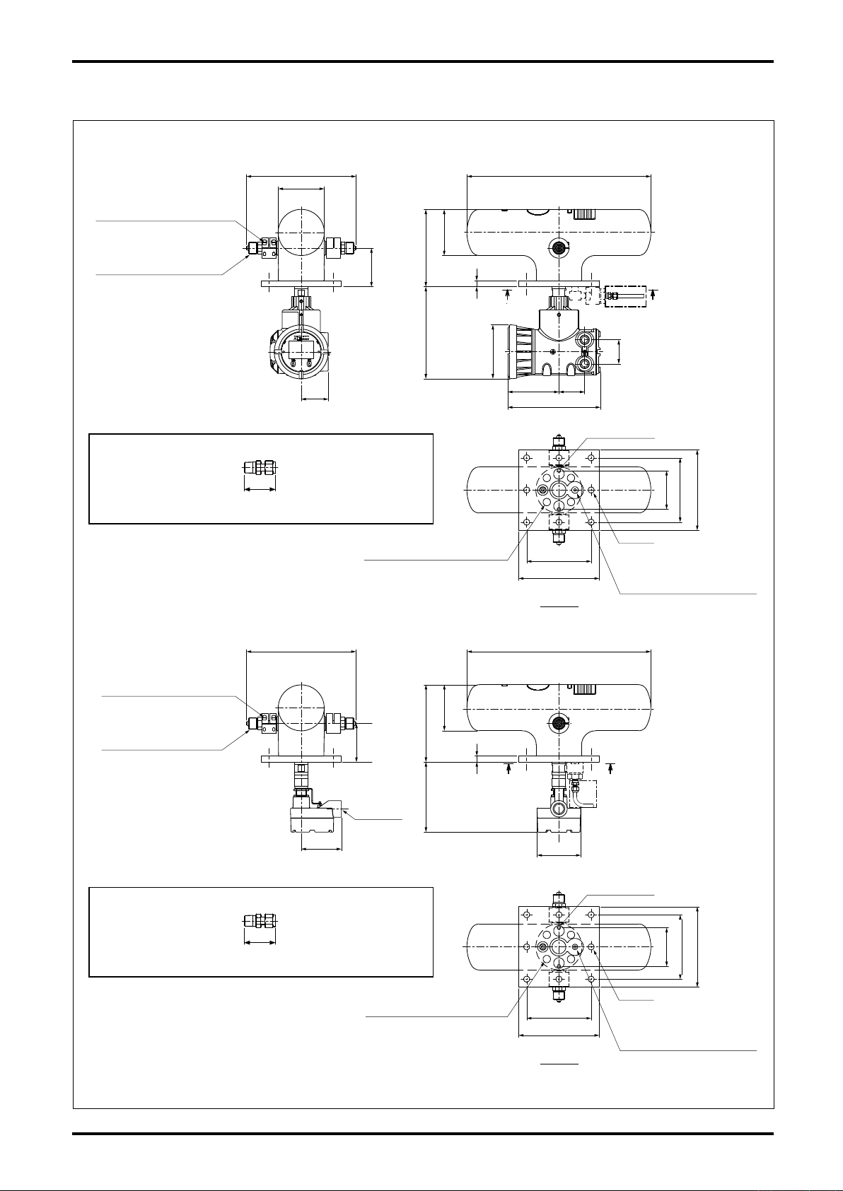
4. PART NAMES AND OUTLINE DIMENSIONS
Transmitter integrally mounted
●
Transmitter separately mounted
●
10
Fig. 4.1 Outline Dimensions
Page 11
L-737-3-E
φ134
67
4-M6×8
230
127 103
100
64
7
50
125
60
188
60
30
60
30
344
233
61.7
171.5
46
CableentryG3/4
CableentryG3/4
Hold-down
hardware
(2×1)
Stanchion(2)
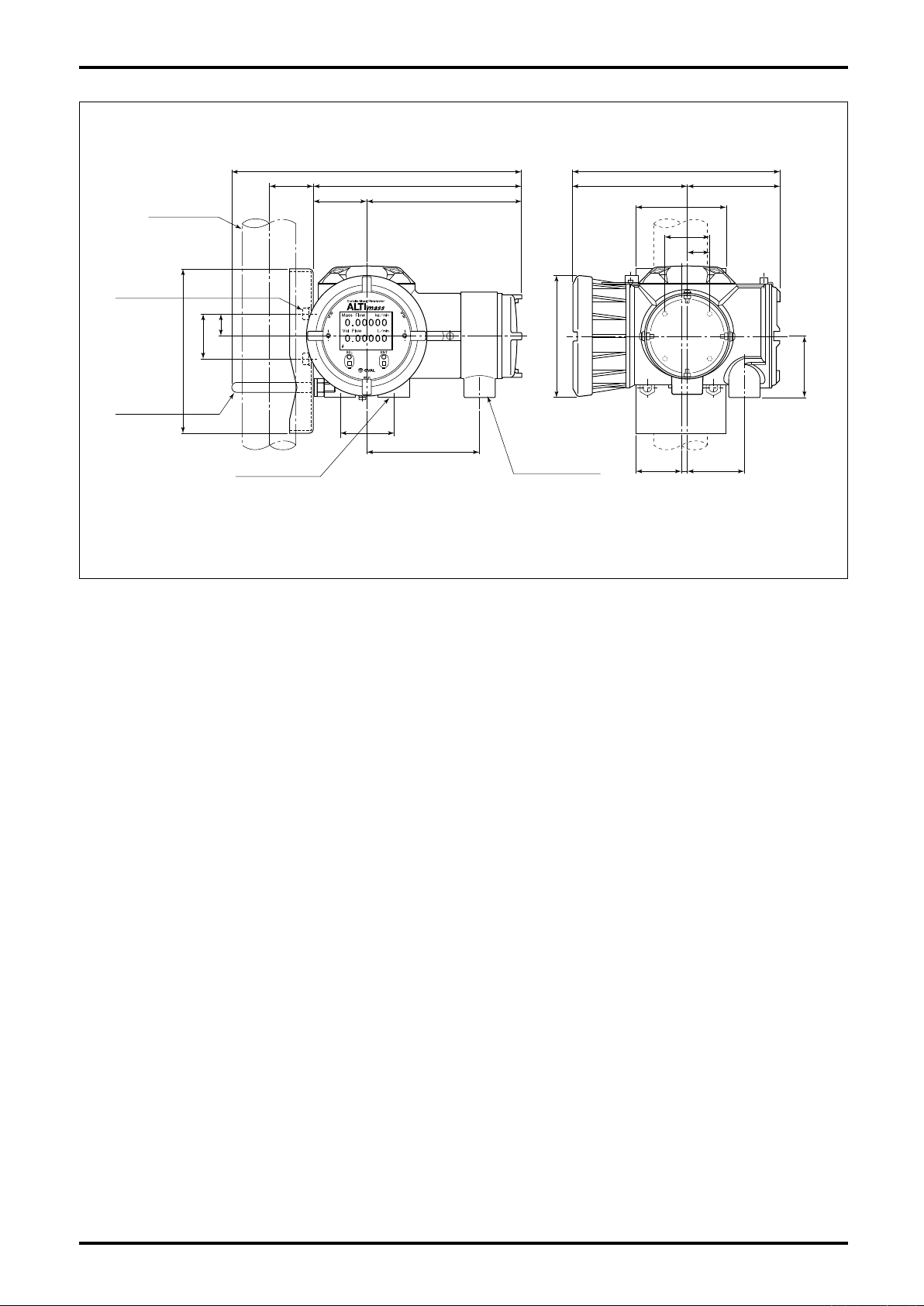
Separately mounted Transmitter
●
Dimensions in millimeters
※ Hold-down hardware are supplied as standard accessories, but the customer is to furnish the stanchion.
Fig. 4.2 Outline Dimensions of Transmitter
11
Page 12
L-737-3-E
5. INSTALLATION
5.1 Considerations at Installation
(1) Select a location easy to access for inspection and maintenance.
(2) Avoid locations subject to severe temperature variation and vibration.
(3) Avoid direct exposure to the sun. (Provide a sunshade or visor if necessarry.)
(4) Avoid locations where there is a risk of immersion in water.
(5) Select a location free from an atmosphere of corrosive gases.
(6) Location should be free from dust and mist.
(7) Keep a distance of at least one meter from sources of electr omagnetic induction, such as la rge
transformers and motors. Install sufficiently away from motors, pumps, or other sources of high vibration.
(8) To ensure consistent and accurate measurement, adhere to the instructions for tubing clamps on page 16.
(9) To ensure accurate and consistent measurement, use the Coriolis flowmeter in a location where piping
vibration is kept below 0.3G.
(10) Instal the control valve downstream of the flowmeter.
Where cavitation may possibly occur, install the valve at least five meters away from your meter.
5.2 Physical Orientation
Physical orientation does not affect the performance of this unit. It can be installed either in a horizontal or
vertical run. However, with metered fluids that tend to produce bubbles and/or sediments, or where process
fluid removal or purging is conducted after measurement, install the unit in a vertical run.
5.3 Piping Instructions
5.3.1 Standard Piping Conditions
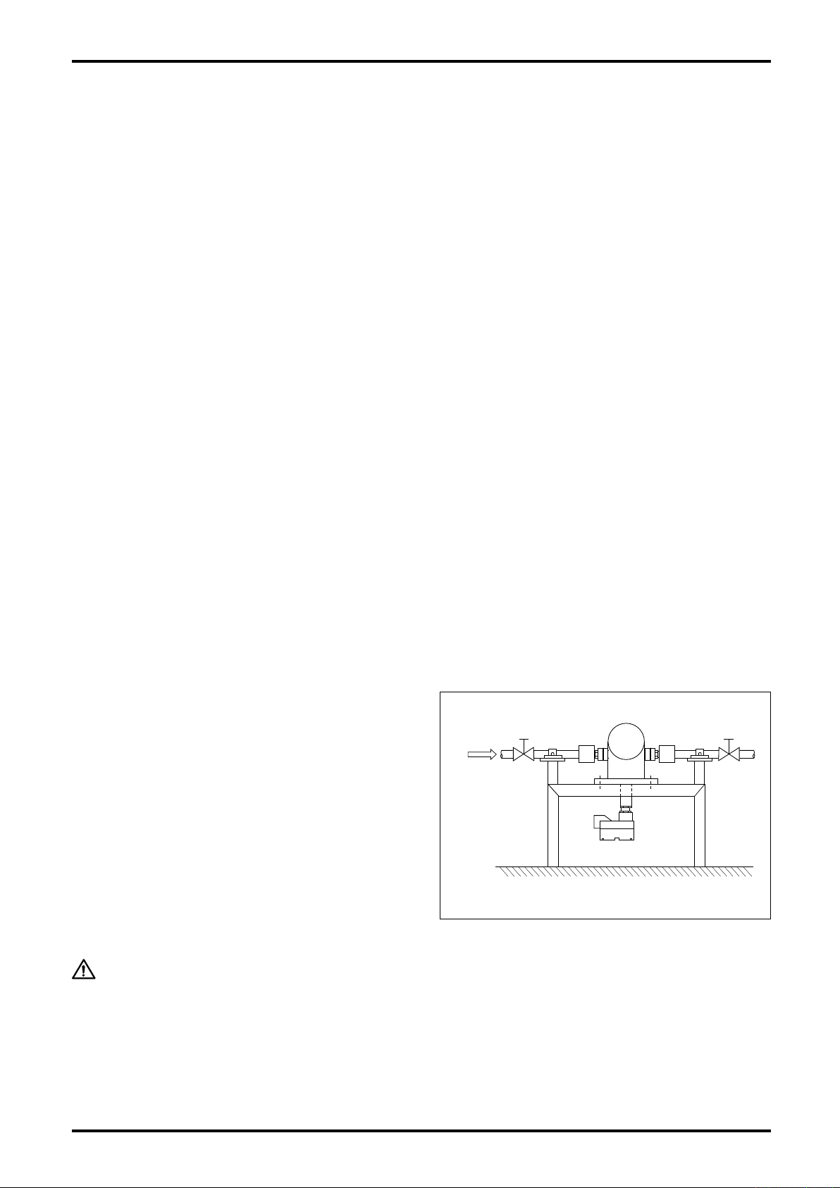
(1) A Coriolis mass flowmeter is unaffected by the
flow pattern of process fluid.
T h e r ef o r e , it do e s no t r e q ui r e a n y fl o w
straighten e r. Howeve r, c o n n e c tion w i t h a
deformed pip e re quires use of a con centric
reducer or tapered pipe.
(2) Locate the meter sufficiently away from known
sources of vibration and pulsation.
(3) For zeroing, provide a valve that can stop the
flow completely downstream of the meter. We
recommend to provide another valve upstream
of the meter for servicing.
(4) Avoid piping stress concentration on the sensor.
Flow
Direction
Valve
Fig. 5.1 Standard Piping Conditions
Valve
CAUTION:
12
Although this meter is designed for installation on a mounting base, piping
clamps must be provided both upstream and downstream of the meter.
Page 13
L-737-3-E
5.3.2 Influences of Vibration and Pulsations
Generally, Coriolis mass flowmeters can best make measurements with minimal pipeline vibration and
pulsations. In applications where vibration and pulsations are not negligible, take the following measures:
(1) Locate the meter sufficiently away from the sources of vibration and pulsations.
(2) Provide attenuators, such as flexible tubes and chambers. However, if this meter itself is the very source
of transmitting vibration to these elements during its operation, a drift in zeroing may result.
To get around this problem, take necessary countermeasures by, for example, locating such elements of
vibration sufficiently apart from the meter.
(3) Close shutoff valves upstream and downstream of the meter at process flow shutdown. (For the sake of
preventing erratic signal generation at shutoff, be sure to prevent pressure buildup inside from exceeding
the max. allowable pressure of the meter.)
(4) If meters of the same kind are to be installed in the same tubing, locate them sufficiently apart (at least 5
times the face-to-face length across the meter) and secure each meter with sturdy supports.
5.3.3 Prevention of Cavitation
Cavitation can cause a loss of meter accuracy in measurement. Maintain line pressures that will not cause
cavitation upstream and downstream of the meter for this reason. Avoid making such an arrangement as to
open the line to the atmosphere immediately downstream of the meter. Care must be exercised particularly in
handling liquids of low steam pressure.
In practice, recommended minimum back pressure (pressure on the downstream side) of the meter is calculated by the formula:
Pd=3ΔP+1.3Pv
Where Pd : Downstream pressure (MPa [absolute])
ΔP : Pressure loss across the flowmeter (MPa)
Pv : Steam pressure at the temperature during measurement (MPa [absolute])
5.3.4 Prevention of Excessive Flow Rate
CAUTION:
Exceeding the meter's maximum flow rate will not significantly reduce the
meter's long term durability. However, the output will be held at 110% of the
allowable full scale flow rate.
5.3.5 Keeping the Sensor Unit Completely Filled
CAUTION:
The sensor must be filled with the process fluid during measurement.
A partially filled sensor unit results in large errors particularly at zeroing.
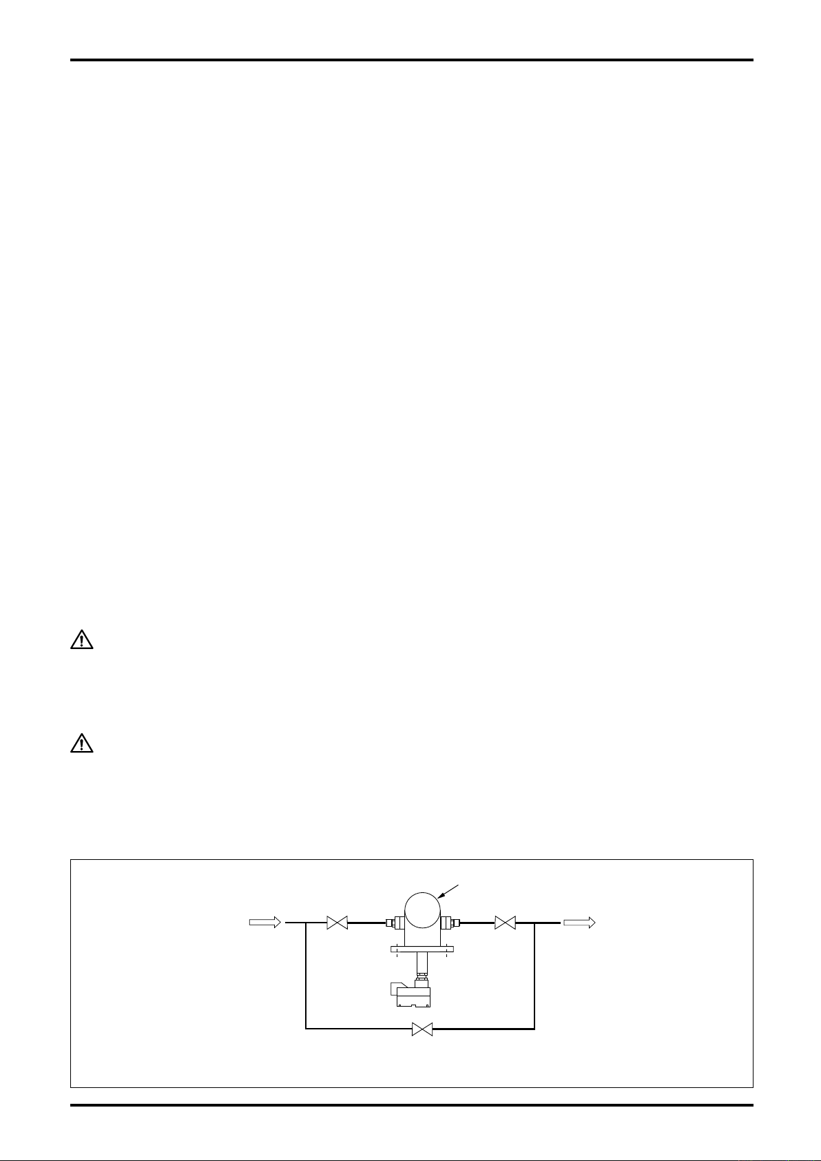
5.3.6 Bypass Line
For maintenance and servicing, it is good practice to provide a bypass loop.
Flow
Direction
Valve Valve
ALTImass
Bypass Line
Fig. 5.2 Bypass Line
Valve
13
Page 14
L-737-3-E
5.4 Installation Instructions
This equipment (sensor unit) is connected to the
piping with high pressure cone & thread fitting, 9/16"
dia. 562C. (Connection examples are shown in Figs
5.3 and 5.4.)
Connector: High pressure cone & thread connection,
9/16" dia. 562C (male thread 1・1/8 - 12UNF)
Set the collar so that the groove faces out.
M6 Hex Soc. Hd. Bolts
Sensor Unit (body)
Sensor Unit (connector)
Piping (Connectors)
Piping
Connector
Clamp
9/16−18UNF LH
Gland Nut
Collar
Fig. 5.4
Fig. 5.3
5.5 Sensor Unit-to-Piping Connection Guidelines
5.5.1 Machining the Female Connector (for reference)
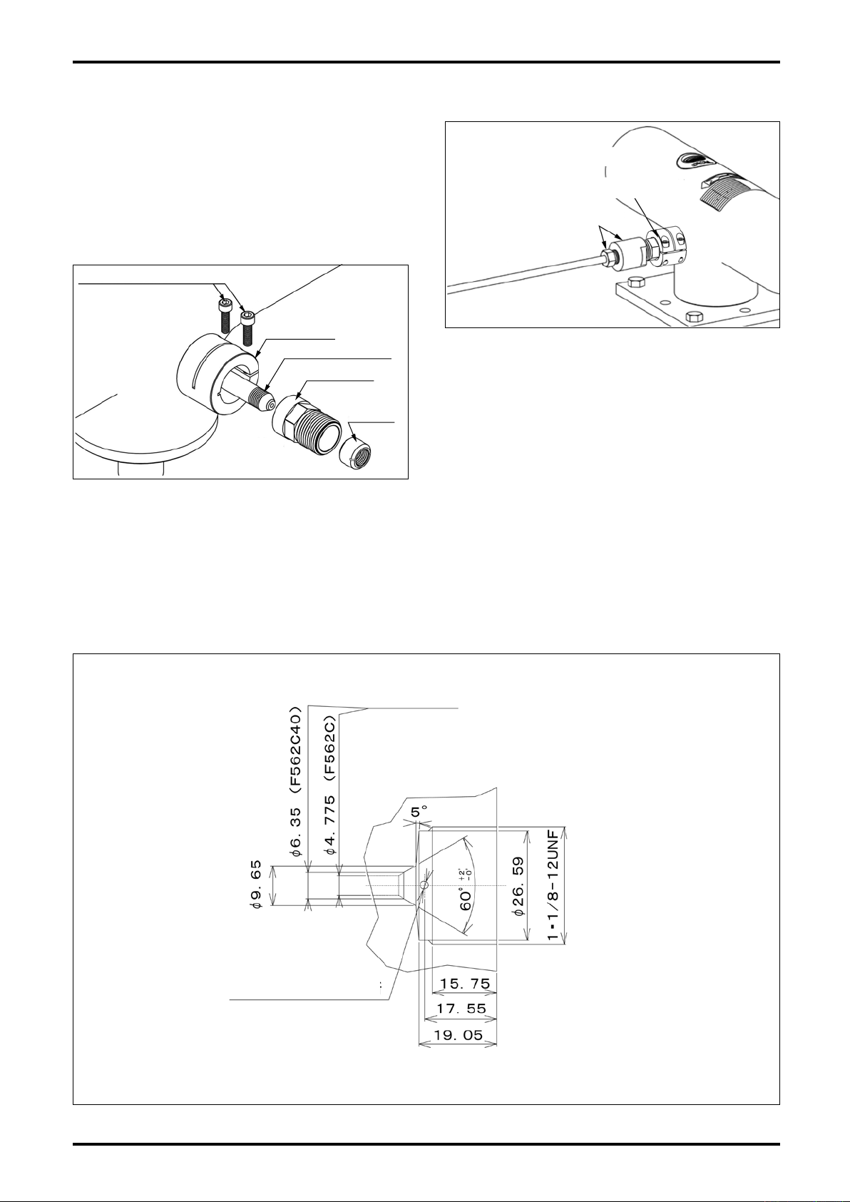
Fi g. 5.5 is a machining dr awi ng for pr epar ing the high pressure cone & t hread conn ection, fe male
connector. See also Fig. 5.6 "Detail Drawing of Connectors".
φ6.5 max. must
be kept strictly.
14
To the Meter
(Sensor Unit)
Weep Hole φ2.34
(2 places)
Fig. 5.5
Page 15
L-737-3-E
5.5.2 Connection Procedure
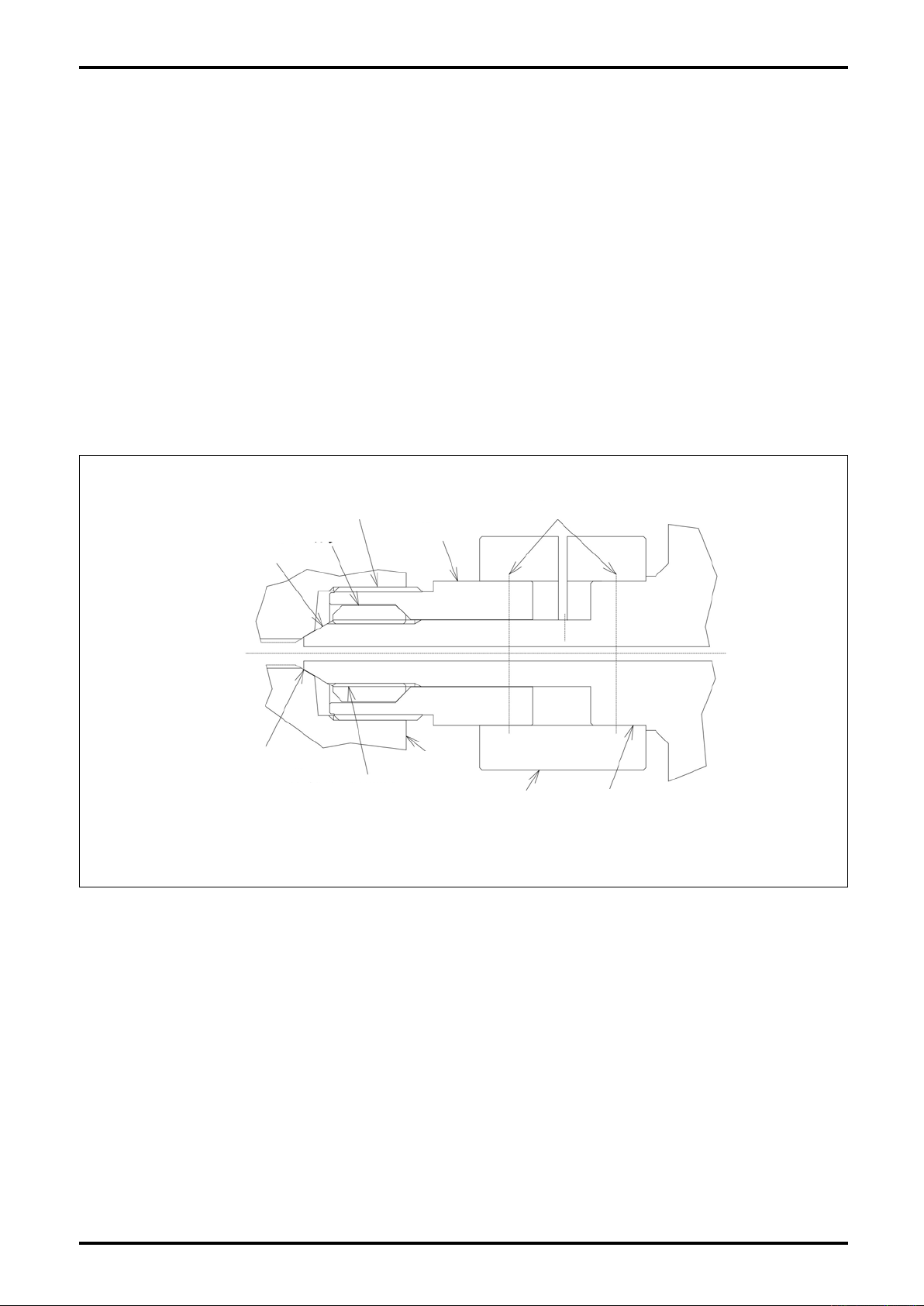
(1) Loosen two M6 hex socket head bolts attached to the connector clamp.
(2) Slide the gland nut onto the male connector and insert the collar as shown in Fig. 5.6 (reverse thread).
Collar position is correct if it has been screwed in to the point where one or two threads are visible at the
end of male connector. Normally it is installed in place at our factory.
(3) Ensure that both the cone of the male connector and the customer furnished female connector are clean.
(4) Insert the male connector into the female connector and finger tighten the gland nut. Ensure that the male
connector and female connector are aligned in their axis at this time.
(5) Tighten the gland nut to a tightening torque not exceeding 279kgf・cm [27.4N・m]. When tightening,
hold the female connector using a wrench.
(6) Insert the connector clamp until it comes to the stepped part of the sleeve.
(7) Tighten two M6 hex socket head bolts attached to the connector clamp to secure the gland nut-to-sleeve
firmly.
1・1/8-12UNF
Male Connector
(See Figs. 5.4 and 5.6.)
Collar
Gland Nut
M6 Socket Head Bolt (2 Places)
Flowmeter
Body
Metal Seal
9/16-18 UNF LH
Fig. 5.6 Detail Drawing of Connectors (high pressure cone & thread connection, 9/16" dia. 562C)
Female
Connector
Connector
Clamp
Sleeve
15
Page 16
L-737-3-E
Piping Clamp
Piping Clamp
Valve
50 to 500mm50 to 500mm
Pedestal
Mtg. Base
400mm
min.
OUT
IN
Increase the rigidity of
the whole assembly
surrounded by dotted
line as high as possible.
Secure firmly using
anchor bolts, etc.
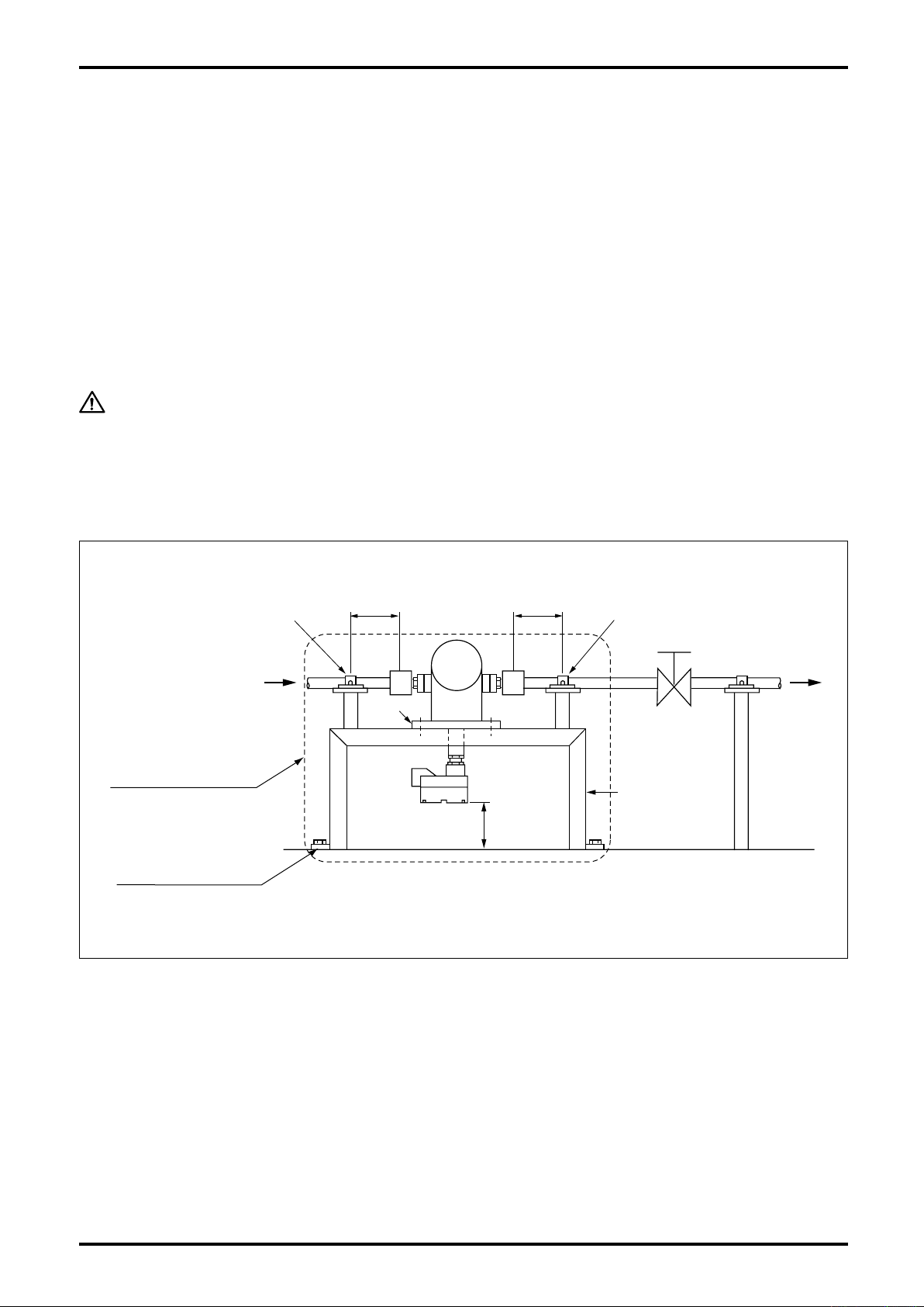
5.6 Securing the Sensor Unit and Piping Clamps
To ensure accurate and consistent measurement, observe the following guidelines:
This is particularly important in applications where excessive piping vibration is observed, or during low flow
measurement.
◦Secure adequate rigidity between the mounting base and piping clamps both upstream and downstream.
◦Ensure rigid installation of piping clamps without using cushioning materials, such as rubber pads.
◦Secure adequate rigidity of the piping assembly itself from the sensor unit to piping clamps.
◦A change in the spring elements in the area surrounded by dotted lines may cause zero drift.
The sensor unit and mounting base are secured with four M10 bolts (designed to prevent them from
loosening) when shipped from the factory. On the rare occasion you find loose bolts, retighten them.
◦Secure the mounting base to a sturdy pedestal that is firmly fixed to a place without vibration.
CAUTION:
Secure the sensor unit firmly to a sturdy pedestal through the mounting base,
using M12 bolts and nuts (customer to furnish). With possible inadequate
seating of the mounting base on the pedestal in mind, OVAL furnishes
eight sets of spherical washers and four sets of flange nuts as standard
accessories with the product. Use them in combination with M12 bolts.
16
Fig. 5.7 Piping Clamps
Page 17
L-737-3-E
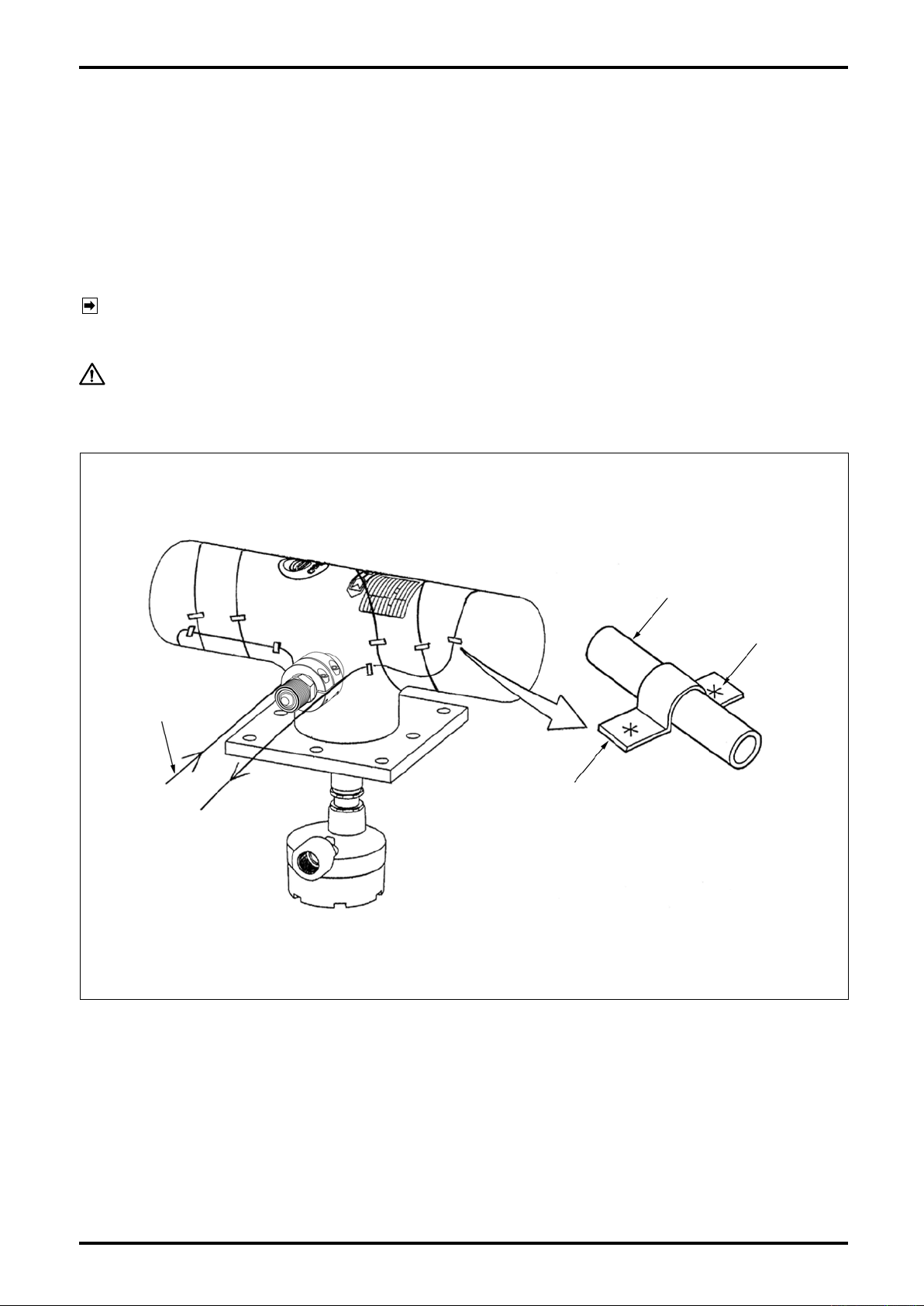
5.7 Heat Insulation Work
In applications where the process fluid is of low or high temperatures, only the sensor unit should be heat
insulated. Do not insulate the adapter and terminal box. We recommend simple sensor lagging to facilitate
inspection and maintenance. Exclude the transmitter electronics.
(1) Careful attention should be paid to the maximum permissible temperature when steam trace is applied.
Maintain the tracing temperature around that of the process fluid (see General Specifications).
(2) If steam, warm water or oil is used, secure by spot welding the copper tubing, or of other material, to the
sensor unit when you spirally wrap the tubing around the sensor unit (Fig. 5.8).
NOTE: To minimize transmission of oscillation to the sensor, the spirally wrapped copper tubing should
start and end at locations as close to the connector as possible (see Fig. 5.8).
CAUTION:
Do not use electric heaters which can be a source of noise.
Copper
Tubing
Sensor Unit
Tubing
Spot Weld
Tube Retainer
(Material: SUS sheet)
Terminal Box
Fig. 5.8 Heat Retention Work
17
Page 18
L-737-3-E
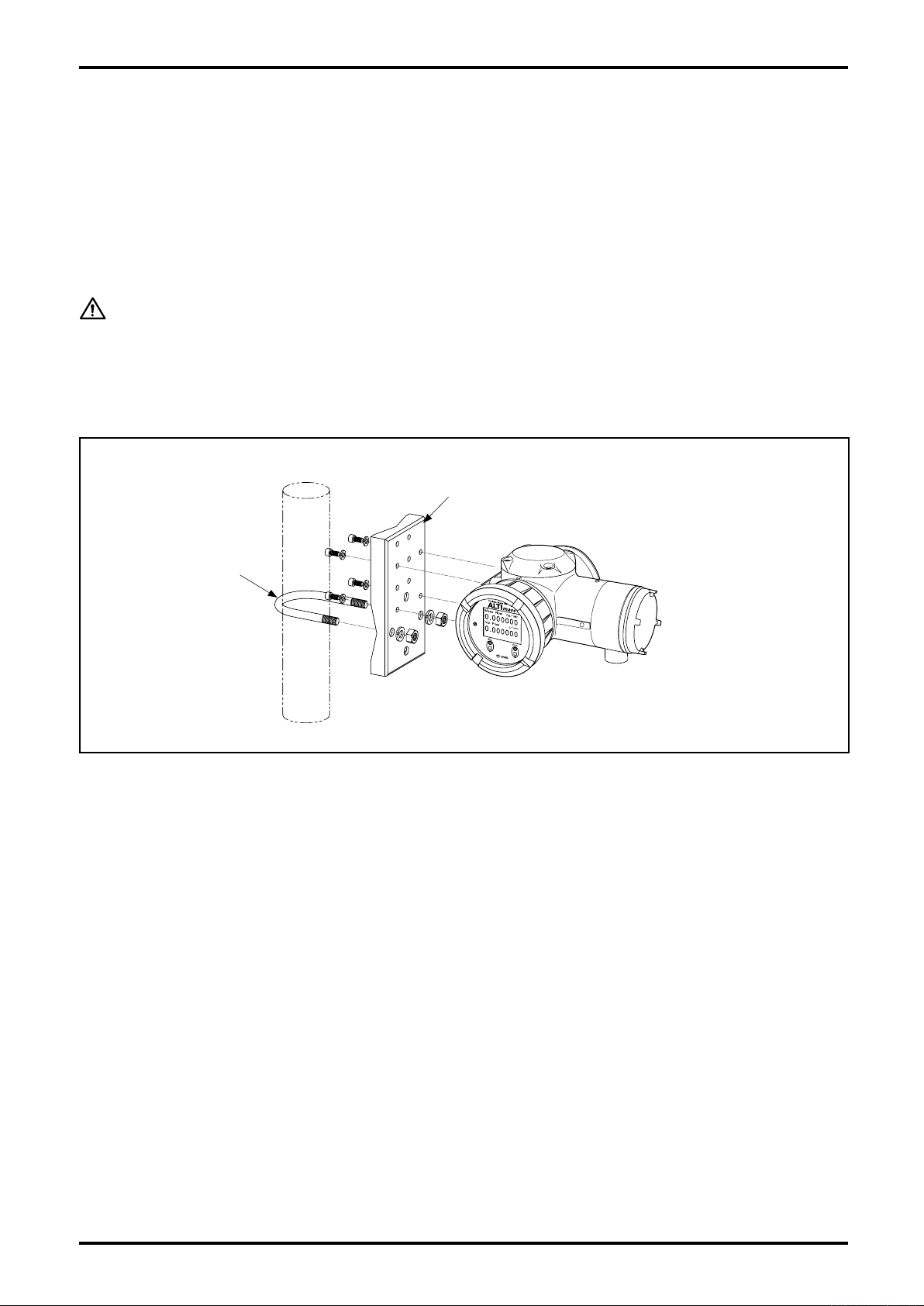
5.8 Separately Mounted Transmitter Installation
(1) The maximum transmission cable length varies with the type of sensor unit: locate the transmitter within this
range.
(2) Secure the transmitter to a horizontal or vertical steel pipe 2 inches in nominal size using the U-bolts
furnished as standard accessories.
(3) Installation location should be accessible for maintenance and in good environment.
(4) The customer to furnish the stanchion (steel pipe).
CAUTION
Avoid installation in such location as
① Difficult to access for maintenance and servicing.
② Excessive temperature changes and vibration.
③ Potential immersion in water.
Installation on a vertical pipe
Hold-down hardware ※
U-bolt
(2˝×1) ※
※: U-bolts, hold-down hardware and bolts
are standard accessories.
Fig.5.9
18
Page 19
L-737-3-E
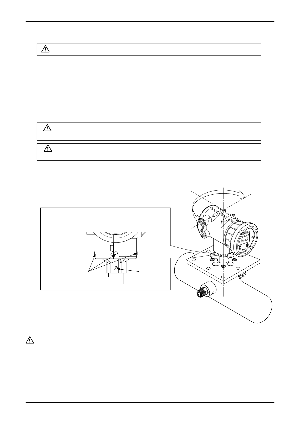
5.9 How to Change Transmitter Orientation
WARNING: Be sure to turn off power before you start working.
To change transmitter orientation, follow the steps given below:
(1) Turn off power.
(2) Make preparations for conduit and cable so that they will by no means cause you any trouble while
changing transmitter orientation.
Work on a level plane with the transmitter up and the sensor secured so that loosening bolts will not
cause the transmitter to come off.
(3) Loosen bolts holding the transmitter adapter with hex wrench. See Fig. 4.10 (M8 hex socket head
screws at four places).
WARNING: Never loosen the hex socket head screws located on the
transmitter body.
WARNING: You may loosen bolts but never separate the transmitter from
the sensor unit.
(4) Rotate the transmitter to the desired position and secure it with setscrews (four places).
Transmitter rotatable over an arc of 180°max.
Loosen four hex socket head screws (M8) at the
adapter and change the transmitter orientation.
Never loosen these screws
located on the transmitter body.
M8 Setscrew
(4 places)
Fig.5.10
CAUTION
The transmitter may be rotated over an 180°arc as shown in Fig. 5.10, but rotating it
beyond 180°will twist the harness from the sensor unit to the extent the equipment is
damaged.
(5) Confirming that the transmitter is secured in place, make conduit and wiring connections.
(6) Verify that the flowmeter operates properly.
19
Page 20
L-737-3-E
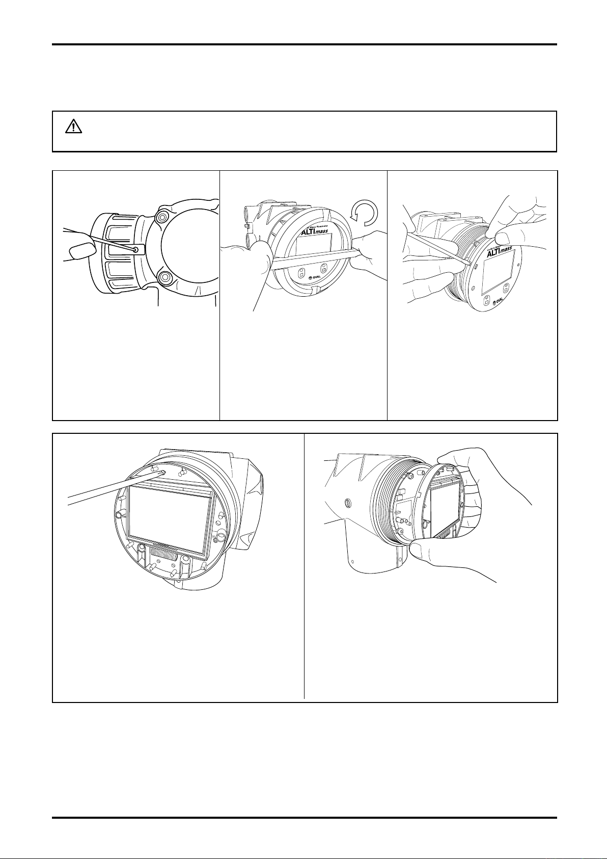
5.10 How to Change Transmitter Display Orientation
The transmitter display may be rotated through 360 in steps of 90°within the housing.
WARNING: Be sure to turn off power and discharge your static electricity before you
work.
① Remove the locking part.
④ Loosen display unit fitting screws (3 places) with
precision flathead screwdriver. "Set washers" to
prevent screws from falling out are attached on the
back of display; do not completely remove screws.
② Using a flat tool 10mm wide
approx., turn the display lid
counterclockwise to loosen,
and loosen further by hand. (Be
careful so as not to damage the
finish.)
Fig.5.12Fig.5.11
⑤ Separate the display unit.
③ Disengage the hooks (3 places).
(Recommended tool: Precision
flathead screw-driver)
Fig.5.13
20
Fig.5.14
Fig.5.15
Page 21
A
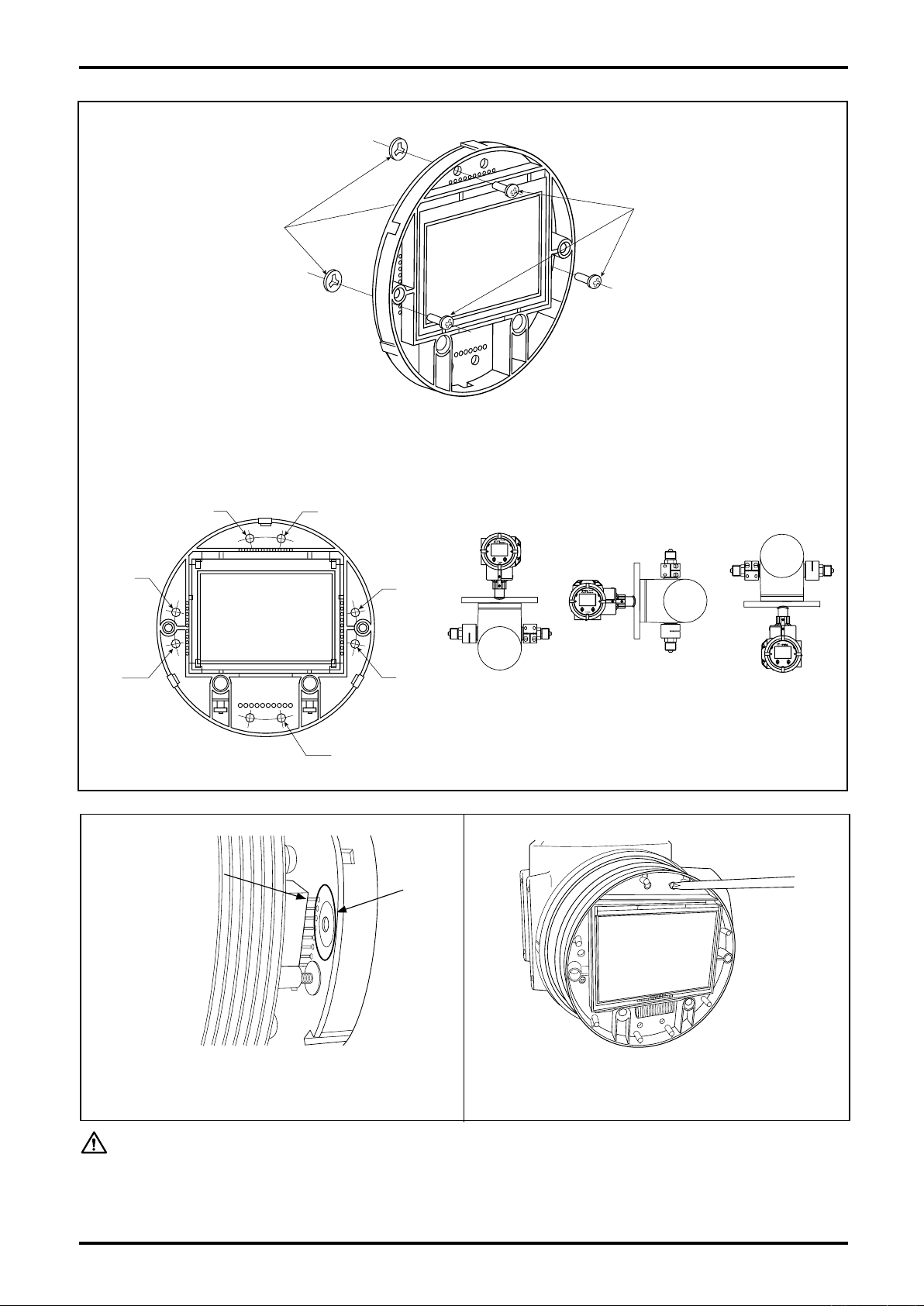
B
C
A.B
B.C
A
C
LCD fitting screws
Set washers (3 places)
⑥ For the display unit that has just been removed, it is necessary to take off fitting screws once, adjust the
orientation and re-install them. Shown below are the location of screw holes for different orientations.
(M2.6, 3 places)
L-737-3-E
A
Liquid service,
horizontal run
B
Vertical run
C
Gas service,
horizontal run
Fig.5.16
Connector
pins
Depending on
the transmitter
type, shapes of
the connector or
peripheral parts
may be different.
⑦ Align connector pins (male) on the transmitter with
mating through holes (female) in the display unit.
Display
unit
through
holes
⑧ Tighten screws (3 places) at new screw holes and re-
install into the original position.
Fig.5.18Fig.5.17
CAUTION: When tightening the display lid, tighten securely using a flat tool or similar
instrument. Insufficient tightening can affect gas-tightness and sensitivity of
display,s optical switch.
21
Page 22
L-737-3-E
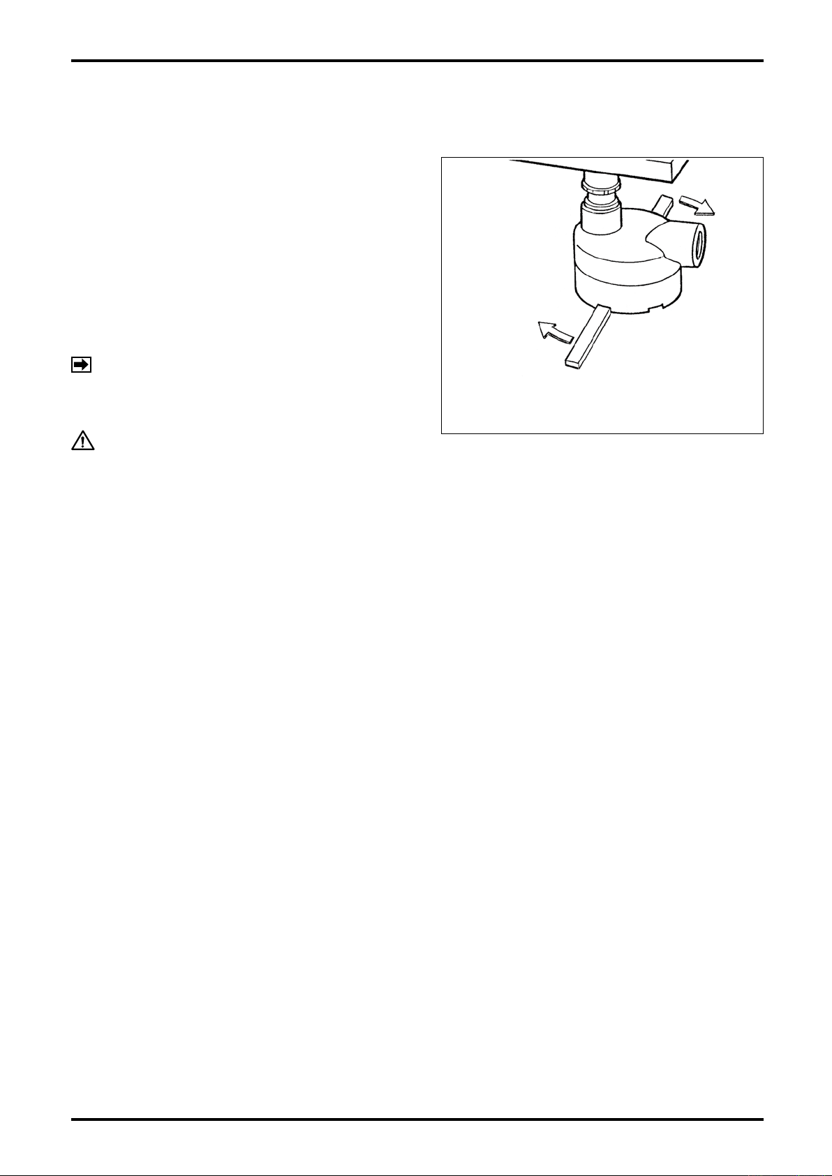
6. WIRING INSTRUCTIONS
6.1 Terminal Box Cover Removal
Cable entrance from the transmitter is found on the
bottom of sensor unit. Remove its c over and make
wiring connections at respective terminals.
(1) Using a flat tool, loosen the terminal box cover by
slowly turning it clockwise and then hand rotate it
further until it comes off.
(2) Removing t h e co ver p r o v i d es ac c e s s t o the
terminal block.
(3) Cover reinstallation is the reverse of the removal
procedure in step (1).
NOTE:
CAUTION:
For the explanation of connecting terminals
i n s i d e th e t e r m i n a l bo x , re f e r to 7.
REMOTELY MOUNTED TRANSMIT TER
AND SENSOR UNIT WIRING.
Terminal Box
Turn
Terminal Cover
A Flat Tool (that will not
scratch the finish)
Fig. 6.1
By changing the physical orientation of terminal
box, the internal wiring could be broken if it
is pulled too strongly. If you desire a change,
consult OVAL.
6.2 Wiring Connections
6.2.1 Cable lead-in
For explosionproof models, use the cable gland supplied in the shipment.
For the specifications of the cable gland, refer to 10.5 About Cable Gland.
22
Page 23

L-737-3-E
6.2.2 Power and output signal connections (both integrally and separately mounted models)
(1) Terminals for wiring connections are found at the back of transmitter housing. Remove the cover
and make wiring connections.
① Using hex wrench, take off latch fitting screw (M3 hex
socket head).
② Using a flat tool, slowly turn the terminal box lid
counterclockwise to loosen and then loosen by hand.
(Use care to avoid damaging the finish.)
Fig.6.2 Fig.6.3
Replaceable fuse
250V, 2A
Status input/output
terminal block
Communication signal
terminal block
Power terminal block
(M4 screws)
Ext. GND terminals
Analog output and pulse
output terminal block (M3.5
screws)
③ Removing the terminal box cover provides access to the cable entry and the power board
holding the power and output signal terminal blocks. The customer is to furnish crimp style
terminals required for power and output signal wiring connections.
Power terminal block for crimp terminals: Round shaped 8.1mm max. O.D. for M4
Output signal terminal block for crimp terminals: Round shaped 7.2mm max. O.D. for M3.5
Status in/out terminal block and communication signal terminal block are of screwless type
and require no crimp style terminals.
Fig.6.4
23
Page 24
L-737-3-E
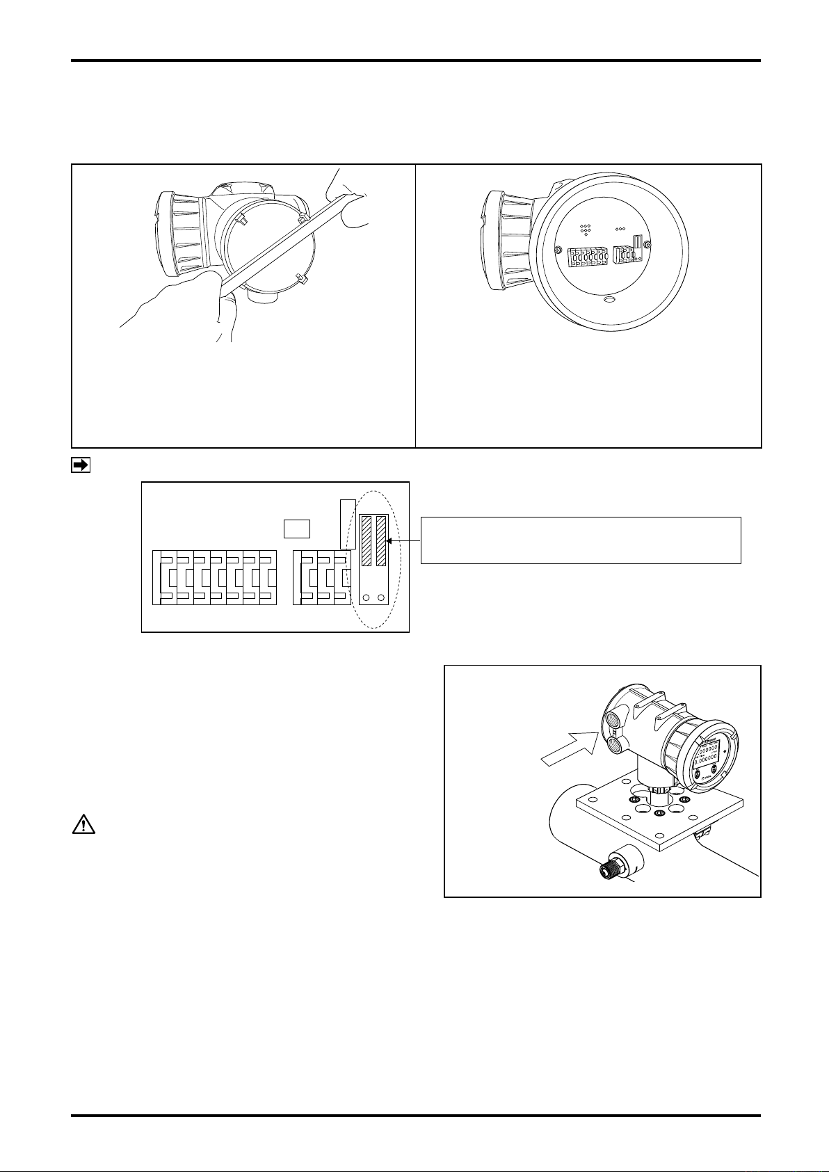
C1
J2
NOL
J1-1
J1-2
COUP
DonotmovethejumpersJ1-1andJ1-2fromtheir
defaultpositions(seethefigureontheleft).
6.2.3 Connections between separately mounted sensor unit and transmitter
Terminals for wiring connections with the sensor unit are found on the side of transmitter housing.
Remove the cover and make wiring connections.
① Using a flat tool, loosen the separately mounted
sensor cover by slowly turning it counterclockwise
and further counterclockwise by hand until it comes
off. (Be careful to avoid damaging the finish.)
NOTE:
About jumper on sensor terminal block in Fig. 6.6.
6.3 Power Supply Lines and Ground Terminal
(1) Power source primary lines are connected to
terminals L (+) and N (-).
(Overvoltage Category II, Pollution Degree 2.)
(2) Connection to earth ground terminal:
Connect only to GND on the power terminal
block or external ground terminal.
② Separating the separately mounted sensor cover
provides access to the terminal block (screwless
terminal block) for the sensor.
Fig.6.6Fig.6.5
External ground
terminal
CAUTION: Supply voltage must be within
the range shown in the
product nameplate attached
to the housing.
Fig.6.7
6.4 Analog Output Wiring
When analog output (4 to 20mA) is to be connected to a receiving instrument, Analog Output 1 has
terminals A1 (+) and terminal A1 (-) while Analog Output 2 has terminal A2 (+) and terminal A2 (-).
Maximum load resistance is 600Ω. Analog output setup procedure appears in 9.7.1 Analog output
functions.
※ Analog output will be invalid if FOUNDATION fieldbus, PROFIBUS PA is selected as communication
interface.
24
Page 25
L-737-3-E
6.5 Pulse Output Wiring
When pulse output is to be connected to a receiving instrument, Pulse Output 1 has terminals P1 (+) and
terminal P1 (-) while Pulse Output 2 has terminal P2 (+) and terminal P2 (-).
If voltage pulse signal is your option, signal transmission length has restrictions on output frequency.
Output frequency Max. transmission length ※
10kHz 10m
1kHz 100m
100Hz 1000m
※ Values are based on wire material 0.75 sq in cross section.
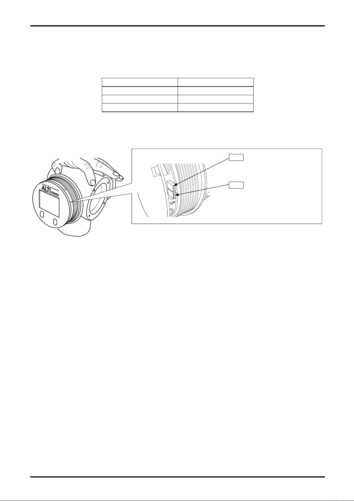
To change from voltage pulse output to open drain pulse output, or vice versa, remove the front lid and
select jumper positions as indicated below.
Pulse output 1 jumper
JP3
OPEN: Open drain pulse
CLOSE: Voltage pulse
Pulse output 2 jumper
JP4
OPEN: Open drain pulse
CLOSE: Voltage pulse
Fig.6.8
Pulse output setup procedure appears in 9.7.2 Analog output.
※ Pulse output will be invalid if FOUNDATION fieldbus, PROFIBUS PA is selected as communication
interface.
6.6 Status Output Wiring
Status output appears across terminals S.O. (+) and S.O. (-).
Status output setup procedure appears in 9.7.3 Status output.
※ Status output will be invalid if FOUNDATION fieldbus, PROFIBUS PA is selected as communication
interface.
6.7 Status Input Wiring
Status input appears across terminals S.I. (+) and S.I. (-).
Status input setup procedure appears in 9.7.4 Status input.
※ Status input will be invalid if FOUNDATION fieldbus, PROFIBUS PA is selected as communication
interface.
25
Page 26
L-737-3-E
6.8 Communication Line Wiring (option)
For communications (option), use terminals I/O. (+) and I/O. (-).
CAUTION: 1. Bell202 HART communications protocol does not use these terminals. It
uses analog output 1 terminal.
2. Other communication interfaces require different handling. Please refer to
the supplementary communication manuals.
FOUNDATION fieldbus communication: "ALTImass series communication
manual for FOUNDATION fieldbus L-740FF"
PROFIBUS PA communication: "ALTImass series communication manual
for PROFIBUS PA L-740PB"
Modbus communication: "ALTImass series communication manual for
Modbus L-740CM"
6.9 Recommended Cables condition
Recommended condition
Item Label
Power
Signal
Communication
Extrnal
ground
L (+)
N (-)
GND
A1 (+)
A1 (-)
A2 (+)
A2 (-)
P1 (+)
P1 (-)
P2 (+)
P2 (-)
S.I. (+)
S.I. (-)
S.O. (+)
S.O. (-)
I/O (+)
I/O (-)
Rating voltage/
allowable current
(at 30℃)
300V over, 2A over
100V over, 0.1A over
600V over, 40A over
Cross-section Solderless terminals
1.25sq to 2.0sq
AWG14 to 16
0.75sq to 2.0sq
AWG14 to 18
※1
0.75sq
AWG18
4sq over
AWG12 over
R-type, 8.1mm less
Size: M4
R-type, 7.2mm less
Size: M3.5
Need no Screwless
terminal type
Directly wiring or
Solderless terminal
(R-type, 8.1mm less)
Maximum
operating
temp.
60℃ over
※2
NOTE:
※1 Please select the cable size to be used with the number of signals.
※2 Depending on the number of output signals used, selection for the right cable material
must be made referring to the table on the next page.
6.10 Terminal Identification of Remotely Mounted Transmitter
26
Item
Sensor unit to transmitter
Terminal
name
TB20
TB21
interconnect cable
(200 meters max.) ※
Terminal
No.
1AB BRN
2AB RED
3AB BLK
1AB PUR Temperature input (inner)
2AB ORG Temperature input (outer)
3AB YEL Temperature input
4AB BLU
5AB GRY
6AB WHT
7AB GRN
Terminal
color
Flow tube drive output
BRN/RED, GRN/WHT, BLU/GRY, PUR/ORG/YEL shielded wires
bundled
Right position pickoff sensor input
Left position pickoff sensor input
Description
Page 27
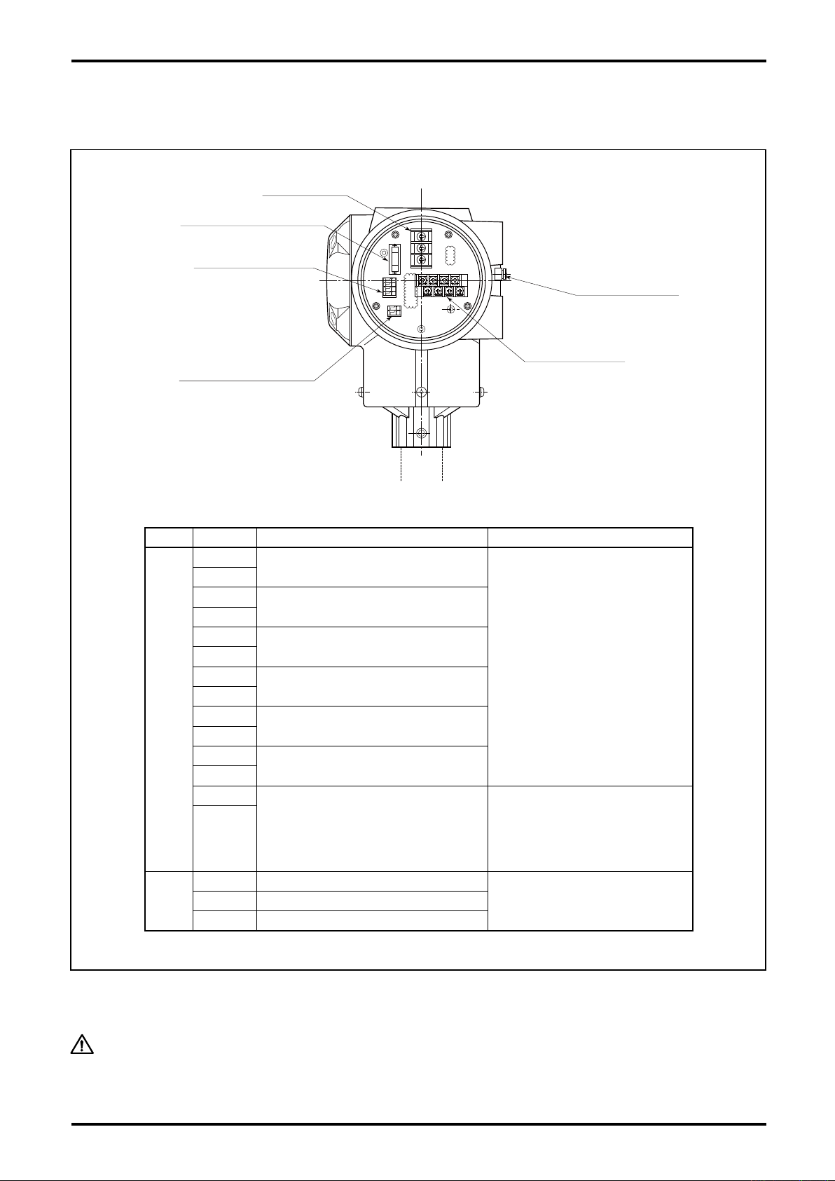
Status in/out terminals
Analog and pulse
output terminals
Power terminals
Replaceable fuse 250V, 2A
Remote output terminals
Ext. GND terminals
6.11 Wiring Diagram
6.11.1 Transmitter power and output signal wiring
L-737-3-E
●
Terminal identification and description
Item Label Description Remarks
Signal
Power
A1(+)
A1(-)
A2(+)
A2(-)
P1(+)
P1(-)
P2(+)
P2(-)
S.I.(+)
S.I.(-)
S.O.(+)
S.O.(-)
I/O(+)
I/O(-)
L(+) Power (with DC power: +)
GND Earth ground
N(-) Power (with DC power: –)
Analog output 1 (4 to 20mA)
Analog output 2 (4 to 20mA)
Pulse output 1
(voltage/open drain output)
Pulse output 2
(voltage/open drain output)
Status input (drain input)
Status output (open drain output)
Expanded in/out
(Modbus communication, etc.)
1. Max. load resistance is 600Ω
for analog output 1 and 2.
2. Pulse output (voltage
pulse) transmission length is
Max. 10m (at 10kHz)
Max. 100m (at 1kHz)
Max. 1km (at 100Hz)
finished O.D: 0.75sq
3. These input and output signals
are invalid for FOUNDATION
fieldbus, PROFIBUS PA and
Modbus communications.
Modbus communication:Max.trans-
mission length1200m at 0.75sq
FOUNDATION fieldbus or
PROFIBUS PA communication:
Max. transmission length 1900m at
0.8sq
Conduct earth grounding work at external ground terminal or "GND" on the power terminal block (Grade
D grounding work).
CAUTION:
Fig.6.9
Incase supplying electric power to this flowmeter, do not fail to connect a
protective fuse of rated voltage 2A max.
27
Page 28
L-737-3-E
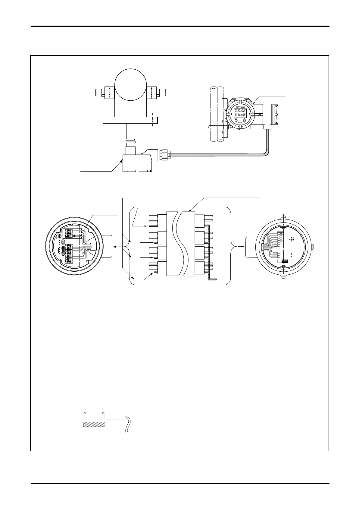
Sensor unit
Terminal Box
T
ransmitter
Cut off shield wires here except for the
shield wire over BRN and RED lines.
Interconnect
cable (Max. 200m)
Transmitter terminal box
Sensor terminal box
Shield
(Protected by black tube)
Shield
(Protected by black tube)
cut
cut
cut
Brown
Red
Green
White
Blue
Grey
Purple
Yellow
Orange
Brown
Red
Green
White
Blue
Grey
Purple
Yellow
Orange
Shield wires:Black
茶
赤
黒
橙
黄
緑
青
紫
灰
白
9mm
7. REMOTELY MOUNTED TRANSMITTER AND SENSOR UNIT WIRING
28
NOTE 1. Make sure to use dedicated interconnect cable.
2. Shield wire preparation
(1) Transmitter end:
As shown in the above figure, bundle shield wires colored in brown/red, green/
white, blue/grey, purple/yellow/orange, twist them, and cover the wires with a black
tube. Then connect only one wire to the terminal box (black) taking care to avoid
potential contact with the housing or conductive parts.
(2) Sensor en
d:
As shown in the figure, cover the brown/red shield wire with a black tube and
connect it to the terminal box taking care to avoid potential contact with the housing
or conductive parts. Clip all shield wires except brown/red as shown in the above
figure.
3. Recommended cable end treatment:
Use of a stick type crimp terminal is not necessary.
Fig.7.1
Page 29
L-737-3-E
8. OPERATION
8.1 Flushing the Piping Assembly
If scale and sludge are expected to be left in the piping assembly, particularly in a new piping assembly,
flush the assembly prior to sensor unit installation.
8.2 Confirming the Sensor Unit for Correct Installation
For safety,s sake, confirm connecting bolts to tightness and gaskets for condition. Make certain of flow
direction at the same time.
8.3 Leak Check
Fill the sensor tube completely with process fluid and check for any leak from connections.
8.4 Supplying the Power
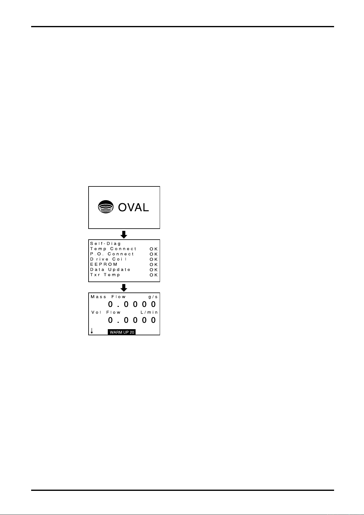
Upon completion of checks for correct wiring connections, supply power. The LCD will show the following
information:
Corporate logo is shown.
Self diagnostics begins.
If nothing unusual is found, "OK" appears at right of
each item, bringing up the next window.
(If NG appears, running a check on that item is
required.
See 9.6.3 Transmitter Check, correct the condition, and
turn on power again.)
Variable view and measurement begins.
8.5 Measurement Line Startup
By starting up the pump, opening valves, etc., carefully allow the process fluid to flow.
8.6 Warm-up
To ensure stability of the measuring conditions of equipment, provide about 20 minutes, warmup period.
(A message "WARMUP 20" stays on after startup. The number shows remaining time (min).)
8.7 Zeroing Procedure
On seeing that the measuring conditions have come to an equilibrium, shut off the downstream valve
completely. Make a zeroing adjustment under these conditions (see the topic under 9.8 Zeroing).
8.8 Readying for Operation
Now preparation for operation is complete. Initiate measurement.
29
Page 30
L-737-3-E
①
②
③
9. DESCRIPTION OF INCORPORATED FUNCTIONS
9.1 Display
9.1.1 Description of display
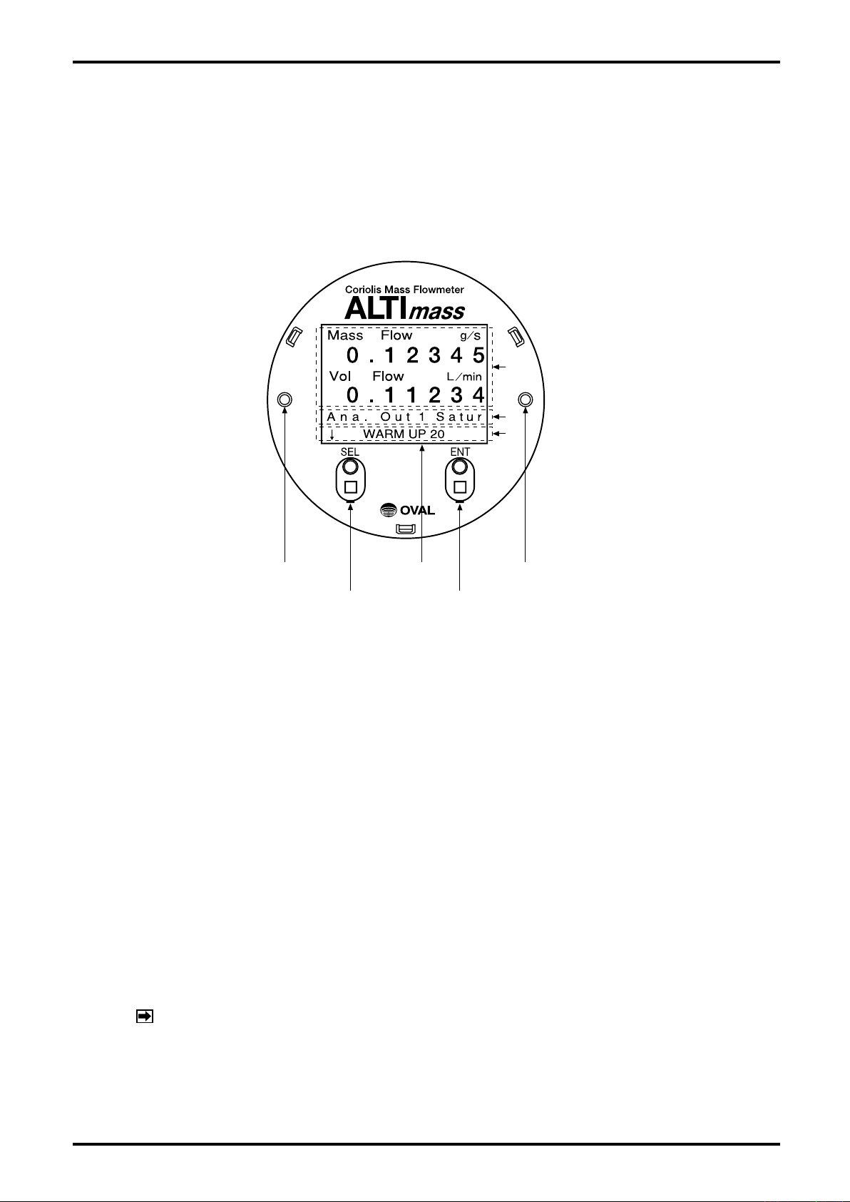
RED LED LED GRN LED
"ENT" switch"SEL" switch
(1) LCD top row (①)
Shows measurements. Other variables also can be shown with switches. (An example at above shows
instant mass flowrate and instant volume flowrate. For details of displayed variables, see 9.1.3 View
variables.)
(2) LCD middle row (②)
Shows an error / status message.
For error messages, see 10.1 Error Messages and 10.2 Status Messages. If more than two messages
exist, they are shown one after another.
(3) LCD bottom row (③)
In the view variables screen, an arrow appears, pointing to the direction of scroll. By reversing the
arrow direction, you can reverse the direction of scroll. (For details, see 9.1.3 View variables.)
A black circle ● may blink on and off at right of arrow. (It indicates that the number of running hours
has exceeded 100,000. For necessary treatment, see 10.2 Status Messages.)
(4) Red LED and green LED
Similar to messages, these LED show the status of flowmeter.
In normal operation, red LED stays off; green LED stays on.
Anything else is indicative of occurrence of something erratic.
See 10.1 Error Messages and 10.2 Status Messages.
(5) "SEL" and "ENT" switches
An infrared switch. Responds to a finger held close to it.
For operating procedure, see 9.1.2 Switch operation.
NOTE:
If the infrared sensors do not respond sufficiently, use LinkTop to adjust the sensitivity.
In case you do not have LinkTop, use a reflecting subject, such as a sheet of paper,
to operate the switches.
30
Page 31
L-737-3-E
9.1.2 Switch operation
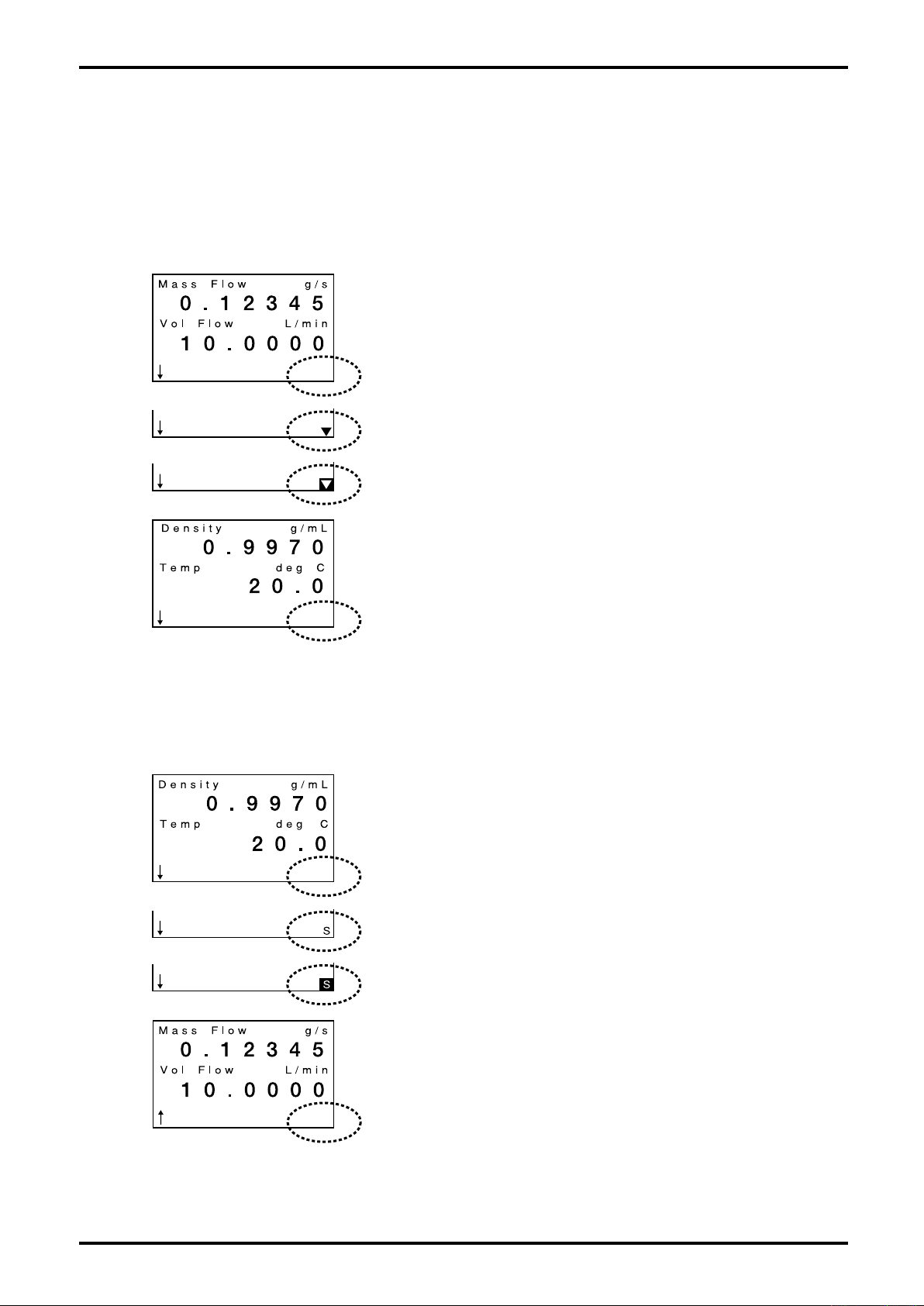
The transmitter has two infrared switches: "SEL" and "ENT". Operation of these switches is described
here. For information about parameter configuration and other functions, see the respective sections.
(1) "ENT" operation
This switch is used for scrolling the display, scrolling the cursor, etc.
Here we cover "ENT" operation as an example of switching variables view screens.
① Touch ENT key at lower right of screen over glass faceplate with
your finger.
When the key responds, a down arrow ▼ appears at lower right of
screen (surrounded by a dotted circle) where nothing was found
as shown in the next screen.
② After down arrow comes on for 0.5 sec, arrow ▼ is highlighted as
shown in the following screen.
③ While the highlighted arrow stays on (0.5s), remove your finger.
Arrow ▼ goes out and the screen changes.
(With your finger held on, you can continue "ENT" operation. It is
beneficial for fast scroll.)
④ End of "ENT" operation
The next screen appears.
(2) "SEL" operation
This operation is used to switch screen direction, increasing the number, parameter select, etc. Here
we cover "SEL1" operation as an example of switching screen direction.
① Touch SEL key at lower left of screen over glass faceplate with
your finger.
When the key responds, a letter S appears at right bottom of
screen (surrounded by a dotted circle) where nothing was found
as shown in the next screen.
② After letter S comes on for 0.5 sec, the letter S appears highlighted
as shown in the following screen.
③ While the highlighted S stays on (0.5s), remove your finger.
Letter S goes out and arrow ↓at bottom left of screen changes to ↑.
(With your finger held on, you can continue "SEL" operation. It is
beneficial for quickly increasing the number.)
④ End of "SEL" operation
Arrow ↓ has changed to ↑.
Operating "ENT" in this state allows the screen to scroll in the
opposite direction.
31
Page 32
L-737-3-E
……
……
……
……
……
……
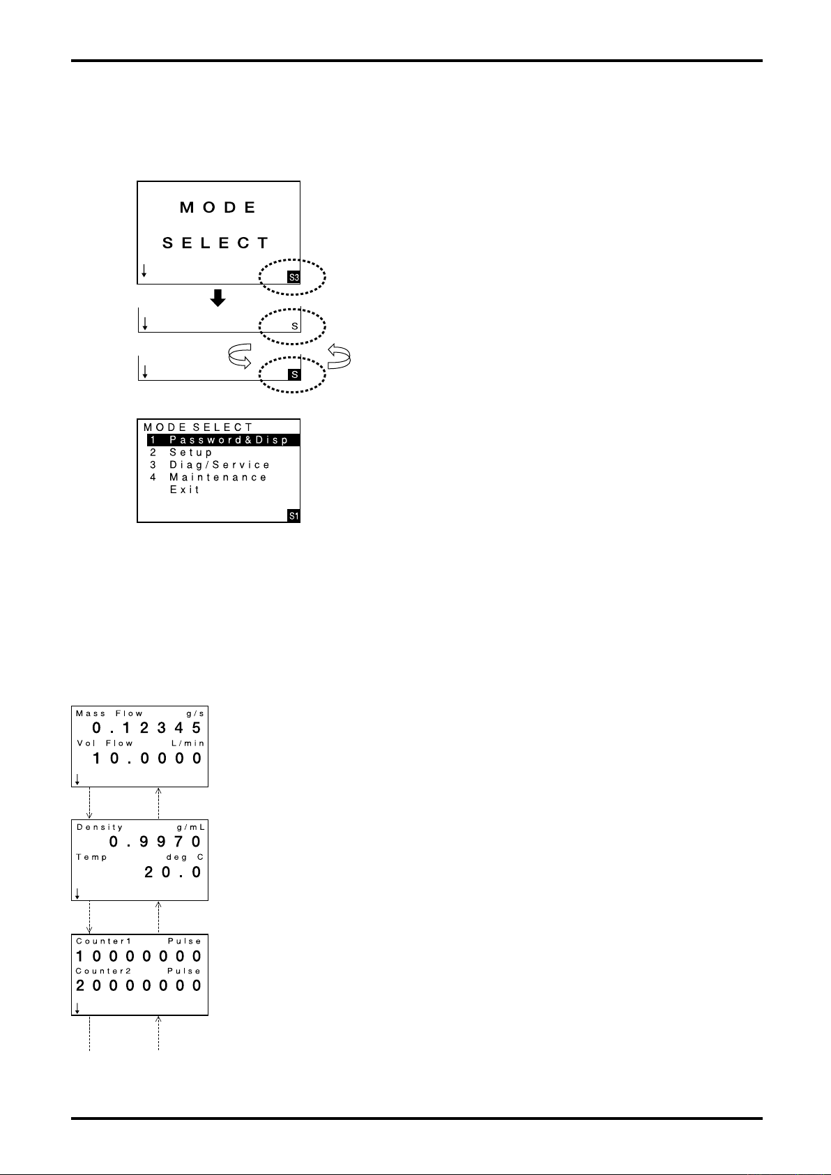
(3) "SEL3" operation
This operation is used to finalize the numeric value that has been changed and activate it, etc.
Here we cover "SEL3" operation as an example of switching to MODE SELECT menu screen.
① Touch SEL key at lower left of screen over glass faceplate with
your finger.
When the key responds, a letter S appears in the highlighted S3
area at lower right of screen.
(On certain screens, letter S3 may appear at lower center of
screen.)
② Hold you finger on.
After letter S comes on for 0.5 sec, the letter S appears highlighted
as shown in the following screen.
③ While holding your finger on, the screen repeats a change between
highlighted and unhighlighted.
On the third appearance of highlighted S (duration 0.5 sec),
remove your finger. A switch to MODE SELECT menu screen
takes place.
④ End of "SEL3" operation
A switch to MODE SELECT menu screen is complete.
9.1.3 View the Variables
(1) Description of displayed information
Shown below is a flow diagram with CA sensor (default settings).
At right of each screen is the description of information displayed in the screen.
The window changes from one screen to another with switch operation. Repeat touching the switch
until the desired screen appears.
●
Mass Flow: Instant mass flowrate
Decimal point placement is alterable by config. (See 9.2.2 Transition chart (1) [No. 1-3-4-1].)
Units of measure are alterable by config. (See 9.2.2 Transition chart (2) [No. 2-1-1].)
●
Vol Flow or Vol Flow(s): Instant volume flowrate
Decimal point placement is alterable by config. (See 9.2.2 Transition chart (1) [No. 1-3-4-2].)
Units of measure are alterable by config. (See9.2.3 Transition chart (2) [No. 2-1-2].)
Click "ENT".
(※1 with ↓)
Click "ENT".
(※1 with ↓)
Click "ENT".
(※1 with ↓)
Click "ENT".
(※1 with ↑)
Click "ENT".
(※1 with ↑)
Click "ENT".
(※1 with ↑)
If fixed density is your option, Vol Flow(s) appears.
Below 0.3g/m in density, volume flow is clamped to 0.
●
Density: Fluid density
Decimal point placement is alterable by configuration. (See 9.2.2 Transition chart (1) [No. 1-3-4-3].)
Units of measure are alterable by config. (See 9.2.3 Transition chart (2) [No. 2-2-1].)
●
Temp: Fluid temperature
Units of measure are alterable. (See 9.2.2 Transition chart (2) [No. 2-3-1].)
●
Counter 1: The number of counts of pulse output 1.
When reading exceeds "99999999", it resets to 0.
The reading is retained irrespective of power cycling.
Can be reset to 0 with Count/Total 1 reset function. (See 9.2.7 Transition chart (6) [No.3-5-1].)
If pulse output 1 related parameter is modified, the counter is reset to 0.
●
Counter 2: The number of counts of pulse output 2.
When reading exceeds "99999999", it resets to 0.
The reading is retained irrespective of power cycling.
Can be reset to 0 with Count/Total 2 reset function. (See 9.2.7 Transition chart (6) [No. 3-5-2].)
If pulse output 2 related parameter is modified, the counter is reset to 0.
32
Page 33
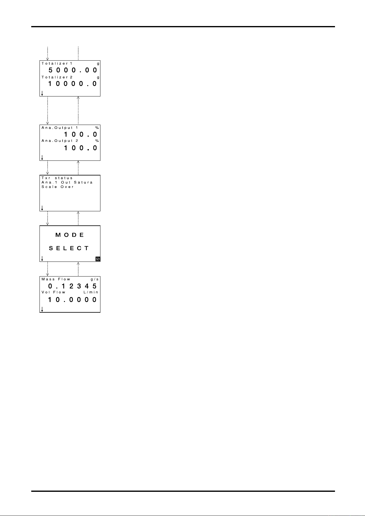
……
……
……
……
……
……
Click "ENT".
(※1 with ↓)
Click "ENT".
(※1 with ↑)
L-737-3-E
●
Totalizer 1: Total flow of pulse output 1
When reading exceeds the max. value, the counter resets to 0 with the next count.
Unit of measure keeps track of the flow unit assigned to pulse output 1.
Decimal point pos. is alterable by configuration (See 9.2.2 Transition chart (1) [No. 1-3-4-4].)
This reading is retained irrespective of power cycling.
Can be reset to 0 with Count/Total 1 reset function. (See 9.2.7 Transition chart (6) [No. 3-5-1].).
●
Shows Totalizer 2: Total flow of pulse output 2
When reading exceeds the maximum reading, it returns to 0 at the next count.
Unit of measure keeps track of the flow unit assigned to pulse output 2.
Decimal point pos. is alterable by configuration. (See 9.2.2 Transition chart (1) [No. 1-3-4-5].)
This reading is retained irrespective of power cycling.
Can be reset to 0 with Count/Total 2 reset function. (See 9.2.7 Transition chart (6) [No. 3-5-2].).
When pulse output 2 related parameter is modified, the counter is reset to "0".
●
Ana. Output 1: % analog output 1
Measurement range: -10 to 110%
●
Ana. Output 2: % analog output 2
Measurement range: -10 to 110%
Click "ENT".
(※1 with ↓)
Click "ENT".
(※1 with ↑)
●
Status / error information
Not shown unless there are errors or status information.
For errors and status information, see 10.1 Error Messages and 10.2 Status Messages.
Click "ENT".
(※1 with ↓)
Click "ENT".
(※1 with ↑)
●
MODE SELECT screen: A screen to enter the setup screen.
Parameter configuration and utilizing various functions starts from this screen.
Click "ENT".
(※1 with ↓)
※1: Scroll direction can be changed by reversing the arrow direction at lower left with "SEL1".
Click "ENT".
(※1 with ↑)
(See "SEL1" operation in 9.1.2 Switch operation (2).)
Back to the initial screen.
(2) To change the style of view variables
・Display/hide of individual items and their priority can be changed.
(For details, see 9.11 Variables view screen setup.)
・Display font size can be changed.
In default setting, alphanumeric is displayed in large fonts; two items appear in one screen. By
selecting the standard font, it is possible to indicate 3 items in one screen.
(For details, see 9.2.2 Transition chart (1) [No. 1-3-3].)
33
Page 34

L-737-3-E
9.2 View Parameters and Description
Numerous parameters and functions are incorporated in this transmitter.
In 9.2.1 Setup menu window, procedures to bring up MODE SELECT menu screen, the initial screen to
show menu items, are covered. For explanation of individual parameters, see 9.2.2 Transition chart.
34
Page 35
L-737-3-E
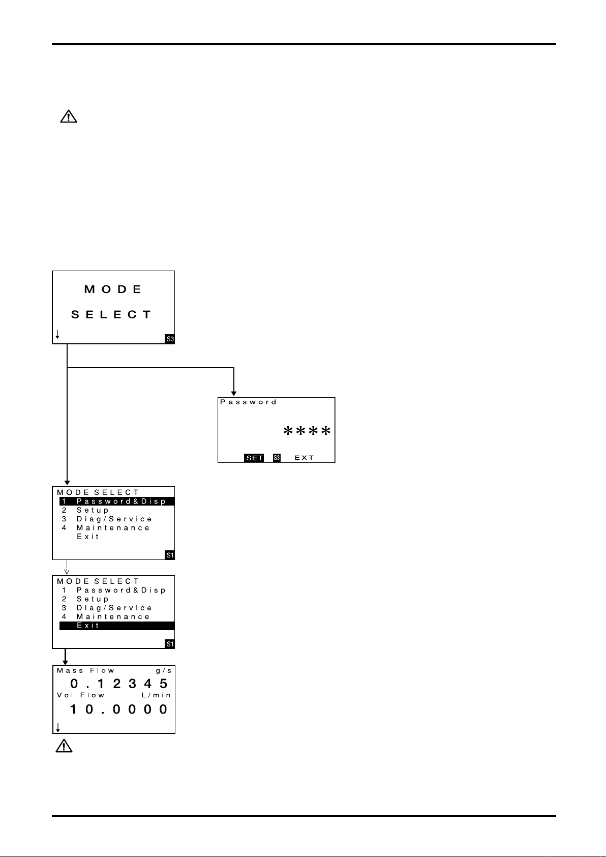
9.2.1 View the setup menu
To reconfigure parameters, etc., it is necessary to bring up the MODE SELECT menu screen at first.
The following is the procedure:
CAUTION:
Notes on Write Protect mode
Write protect mode is a factory preset mode which restricts parameter changes
or executing functions related to measurement accuracy, performance, and
measurement values of this device to prevent posing problems in case the device
is used for custody transfer, etc.
If the target parameter is changed or the function is executed when the device
is set to Write Protect mode, the message "Write protect" ("Write protected" on
LinkTop) is displayed on the LCD screen or screen of communication terminal
such as LinkTop and the operation is not accepted. For the target parameters of
Write Protect mode, refer to the note "*1" shown in sections 9.2.2 to 9.2.7.
Write Protect mode cannot be set or canceled by customer. If setting/canceling of
this mode is required, please contact the distributor you purchased the product.
(1) Bringing up "MODE SELECT" screen
Repeat "ENT" operation until "MODE SELECT" screen appears.
(For detail of operation, see 9.1.2 Switch operation.)
Shown at left is the "MODE SELECT" screen.
(2) Operation on menu view
Click "SEL3". A switch to "MODE SELECT menu" screen takes place.
Operate "SEL3".
★
Password is not set. ★ Password is set.
(If password is enabled, a password setup screen appears.)
(See 9.5 Password Function which will guide you the rest of the way.)
Password setup screen
For the rest of the way, see 9.5 Password
Functions.
3) "MODE SELECT" menu screen appears.
From this screen, you are ready to configure parameters and to run various
functions.
For view parameters and description, see the respective item in 9.2.2 thru 9.2.7
Transition charts.
To return to the normal screen without proceeding to setup process, operate
Operate "ENT" 4 times.
Operate "SEL1".
"ENT" 4 times and select Exit.
Then, operate "SEL1" to return to the normal screen.
(4) Normal screen appears.
CAUTION: If no command arrives within 5 minutes at "Mode Select" menu screen, it returns to
the normal window.
35
Page 36
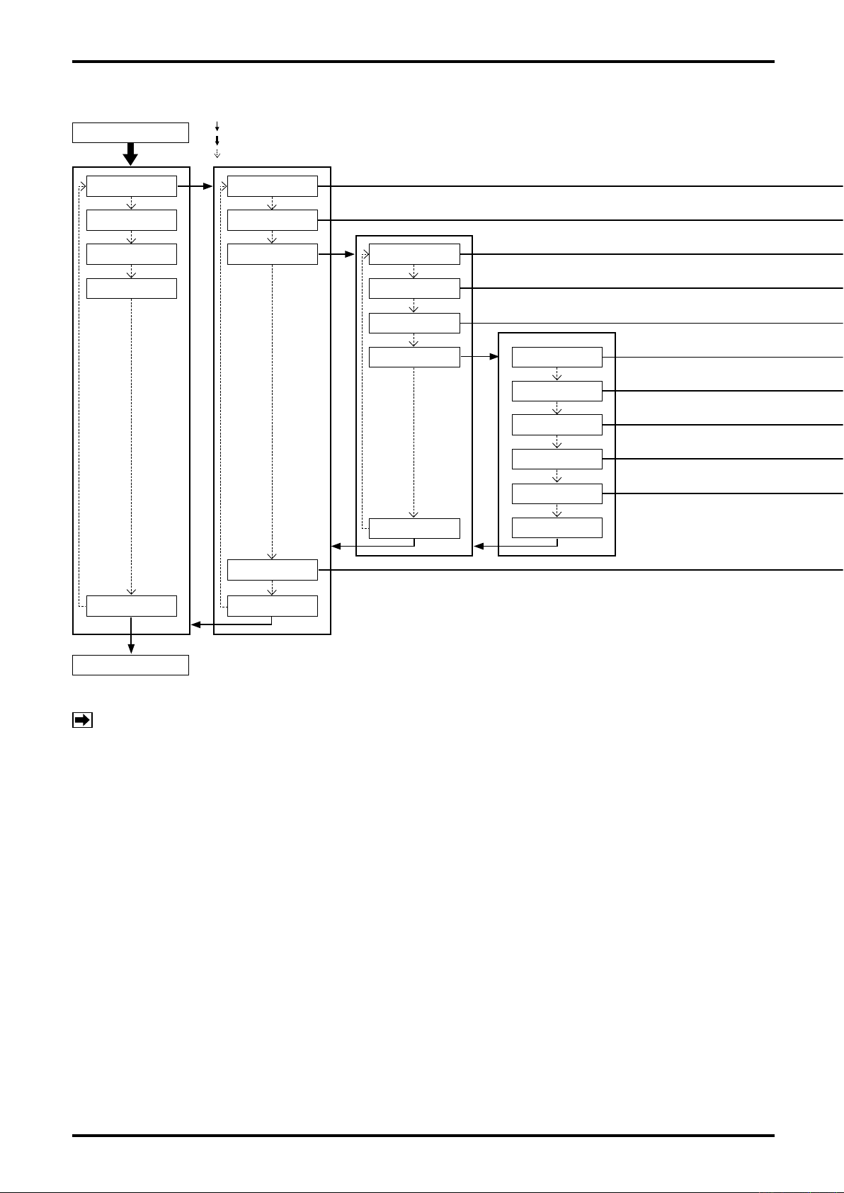
L-737-3-E
9.2.2 Transition chart of view (1)
MODE SELECT
: "SEL1" operation
: "SEL3" operation (For operating procedure, see 9.1.2 Switching operation.)
: "ENT" operation
1.Password & Disp
2.Setup
3.Diag/Service
4.Maintenance
1.Password Set
※1
2.Password
3.Process Var. 1.Var. Priority
4.Back Light
2.Refresh LCD
3.Font
4.Decimal Place 1.Mass Flow
2.Vol Flow
3.Density
4.Totalizer1
5.Totalizer2
Exit
Exit
Exit Exit
Process screen
NOTE:
※1:For this function, the setting change is disabled in Write Protect mode (refer to section 9.2).
36
Page 37
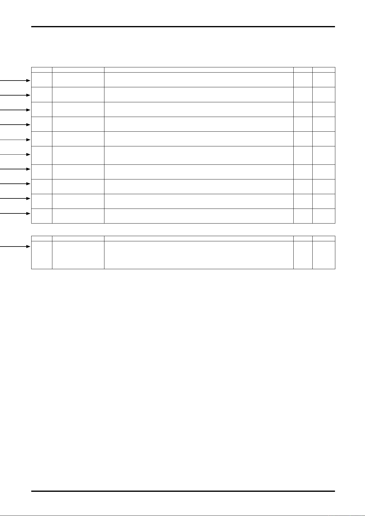
L-737-3-E
No. Item Description Setup Default
1-1 Password Set
1-2 Password
1-3-1 Var. Priority
1-3-2 Refresh LCD
1-3-3 Font
1-3-4-1 Mass Flow
1-3-4-2 Vol Flow
1-3-4-3 Density
1-3-4-4 Totalizer1
1-3-4-5 Totalizer2
No. Item Description Setup Default
1-4 Back Light
Selects password active/inactive. With "ON" selected, entering a password is requested before entering
setup menu screen from "MODE SELECT" screen. This prevents unauthorized password change.
For details of password, see 9.5 Password Function.
Sets a password. To validate the setting, password function in [No. 1-1] requires to be turned "ON".
A precaution to remember: If password is forgotten, there will be no way to change parameters.
Selects run indicator display/hide and priority of variables view.
For details, see 9.1.1 Variables view screen setup.
Changes LCD display refresh rate (ms). Select one from 1: 100ms, 2: 200ms, 3: 500ms, 4: 1000ms, or 5:
2000ms. Select a slower rate if the reading changes too fast, making it difficult to read; select a faster rate if
prompt readout is desired.
Changes LCD font size.
1: Double angle ⇒ Larger font, allowing 2 variables view in one screen.
2: Normal ⇒ Smaller font, allowing 3 variables view in one screen.
Changes dcml pt. pos. in LCD instant mass rate. Select one that matches instant mass rate used. Select
from 1: Auto ⇒ Auto (from 5th dcml. plc. to no fractions, 2: Integer ⇒ No fractions, 3: 1st decimal ⇒ to 1st
dcml place, 4: 2nd decimal ⇒ to 2nd dcml plc., 5: 3rd decimal ⇒ to 3rd dcml plc., 6: 4th decimal ⇒ to 4th
dcml plc.
Changes dcml pt. pos. in instant volume rate on LCD. Select one that matches instant mass rate used.
Select from 1: Auto ⇒ Automatic, 2: Integer ⇒ No fractions, 3: 1st decimal ⇒ to 1st dcml place, 4: 2nd
decimal ⇒ to 2nd dcml plc., 5: 3rd decimal ⇒ to 3rd dcml plc., 6: 4th decimal ⇒ to 4th dcml plc.
Changes LCD decimal point position in density. Set to match the viscosity used. Selectable from 1: Auto ⇒
Automatic, 2: Integer ⇒ No fractions, 3: 1st Decimal ⇒ to 1st dcml place, 4: 2nd Decimal ⇒ to 2nd dcml
place, 5: 3rd Decimal ⇒ to 3 rd dcml place, 6: 4th Decimal ⇒ to 4th dcml place.
Changes LCD decimal point position in total flow 1. Set to match the total flow 1 used. Selectable from 1:
Auto ⇒ Automatic, 2: Integer ⇒ No fractions, 3: 1st Decimal ⇒ to 1st dcml place, 4: 2nd Decimal ⇒ to 2nd
dcml place, 5: 3rd Decimal ⇒ to 3rd dcml place, 6: 4th Decimal ⇒ to 4th dcml place.
Changes LCD decimal point position in total flow 2 on LCD. Set to match the total flow 1 used. Selectable
from 1: Auto ⇒ Autmatic, 2: Integer ⇒ fractions eliminated, 3: 1st Decimal ⇒ to 1st dcml place, 4: 2nd
Decimal ⇒ to 2nd dcml place, 5: 3rd Decimal ⇒ to 3 rd dcml place, 6: 4th Decimal ⇒ to 4th dcml place.
Selects backlight mode. (In an erratic condition, it stays on or blinks depending on its nature.)
1: Off: Backlight stays off.
2: Sleep 5 min: Stays on for 5 min before it goes out.
3: Sleep 10 min: Stays on for 10 min before it goes out.
4: Sleep 20 min: Stays on for 20 min before it goes out.
5: Sleep 30 min: Stays on for 30 min before it goes out.
See 9.4 Off
See 9.3 9999
See 9.11
See 9.4 500ms
See 9.4 Double
See 9.4 Auto
See 9.4 Auto
See 9.4 4th Decimal
See 9.4 Auto
See 9.4 Auto
See 9.4
Sleep
20min
37
Page 38
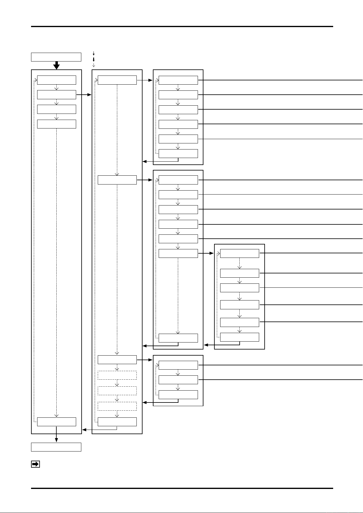
L-737-3-E
9.2.3 Transition chart of view (2)
MODE SELECT
: "SEL1" operation
: "SEL3" operation (For operating procedure, see 9.1.2 Switching operation.)
: "ENT" operation
1.Password & Disp
2.Setup
3.Diag/Service
4.Maintenance
※1
1.Flow Param
2.Dens Param
1.Mass Unit
2.Vol Unit
3.Flow Damp
4.Flow Cutoff
5.Flow Direct
Exit
1.Dens Unit
2.Dens Damp
3.Slug Low
4.Slug High
5.Slug Duration
6.Special Dens
1.Dens Compen
Exit Exit
Process screen
3.Temp Param
4.Outputs
5.Status Input
6.H/L Alarm
Exit
1.Temp Unit
2.Temp Damp
Exit
2.Std Temp
3.Exp Coef
4.Settled Dens
5.Dens Value
Exit
38
NOTE:
※1:For this function, the setting change is disabled in Write Protect mode (refer to section 9.2).
Page 39
L-737-3-E
No. Item Description Setup Default
2-1-1 Mass Unit
Selects instant mass flowrate unit. For available units of measure, see 9.18 Available setup units.
Units of flowrate-related views and settings keep track of the units selected.
See 9.4 kg/min
2-1-2 Vol Unit
2-1-3 Flow Damp
2-1-4 Flow Cutoff
2-1-5 Flow Direct
No. Item Description Setup Default
2-2-1 Dens Unit
2-2-2 Dens Damp
2-2-3 Slug Low
2-2-4 Slug High
2-2-5 Slug Duration
2-2-6-1 Dens Compen
2-2-6-2 Std Temp
Selects unit of instant volume flowrate. For available units of measure, see 9.18 Available setup units.
Flowrate-related units of measure and settings keep track of the units selected.
Changes instant flowrate damping factor (sec).
If flowrate fluctuates excessively, select a larger value; if fast response is desired, select a smaller value (0
to 200 sec).
Changes cutoff (%) of instant mass rate. With respect to the cutoff rate multiplied by max. allowable instant
mass rate and cutoff rate, instant rate is clamped at 0 within the range where - cutoff rate < instant mass
rate < +cutoff rate. If flowrate fluctuates excessively, select a larger value; if measurement down to small
flows is desired, select a smaller value (0 to 5%).
Changes flow direction.
1: Forward ⇒ + flow when the fluid runs in the flow direction of sensor; - flow if the fluid runs opposite to
the flow direction of sensor.
2: Reverse ⇒ - flow when the fluid runs in the flow direction of sensor; + flow if the fluid runs opposite to
the flow direction of sensor.
Selects density unit.
For available units of measure, see 9.18 Available setup units.
The unit of density-related views and settings keep track of the unit selected.
Changes density damping factor (sec).
If density fluctuates excessively, select a larger value; if fast response is desired, select a smaller value.
Sets lower limit density (low end in normal density) for slug flow detection.
Set a value smaller than expected flow density.
Sets higher limit density (high end in normal density) for slug flow detection.
Set a value larger than expected flow density.
Sets the duration required for detecting slug flows. During the preset duration, if measured density falls
below lower limit density [No. 2-2-3] or exceeds upper limit density [No. 2-2-4], it is identified as slug flow to
indicate an alarm.
Sets enable/disable of reference temp. conversion function on density.
1: Off ⇒ Reference temp. conv. function disabled. 2: On ⇒ Ref. temp. conv. function is activated based on
the following formula and the obtained dens. value is used in the view and output, etc.
Dens. after ref. temp. conv. = Measured dens. + {ref. temp. conv. factor [No. 2-2-6-2]×(fluid temp. - ref.
temp. [No. 2-2-6-2])}
Changes the ref. temperature (°C) of the ref. temperature conversion function.
The setting is valid when selection [No. 2-2-6-1] of ref. temperature conversion function is active.
See 9.4 L/min
See 9.3 0.8
See 9.3 0.3
See 9.4 Forward
See 9.4 g/ml
See 9.3 4.0
See 9.3
See 9.3
See 9.3 0
See 9.4 Off
See 9.3 20.00
Liquid: 0.3
Gas: 0
Liquid: 2
Gas: 10
2-2-6-3 Exp Coef
2-2-6-4 Settled Dens
2-2-6-5 Dens Value
No. Item Description Setup Default
2-3-1 Temp Unit
2-3-2 Temp Damp
Changes ref. temp. conversion factor in the ref. temp. conversion function.
The setting is valid when selection [No. 2-2-6-1] of ref. temperature conversion function is active.
Sets enable/disable of fixed density function.
1: Off ⇒ Fixed density function is inactive.
2: On ⇒ Irrespective of density measurement, the fixed density [No. 2-2-6-5] is reflected in the output. (True
density is displayed as density value.)
(With On selected, vol flow is suffixed with (s) to avoid confusion with true density volume output.
Changes fixed density (g/ml) of fixed density function.
The setting is valid when selection [No. 2-2-6-4] of fixed density function is active.
Selects temperature unit of measure.
For available units, see 9.18 Available setup units.
The unit of temperature-related views and settings keeps track of the unit selected.
Changes temperature damping factor (sec).
If temperature varies widely, select a larger value; if fast response is desired, select a smaller value.
See 9.3 0.00024
See 9.4 Off
See 9.3 1.0000
See 9.4 ℃
See 9.3 4.0
39
Page 40
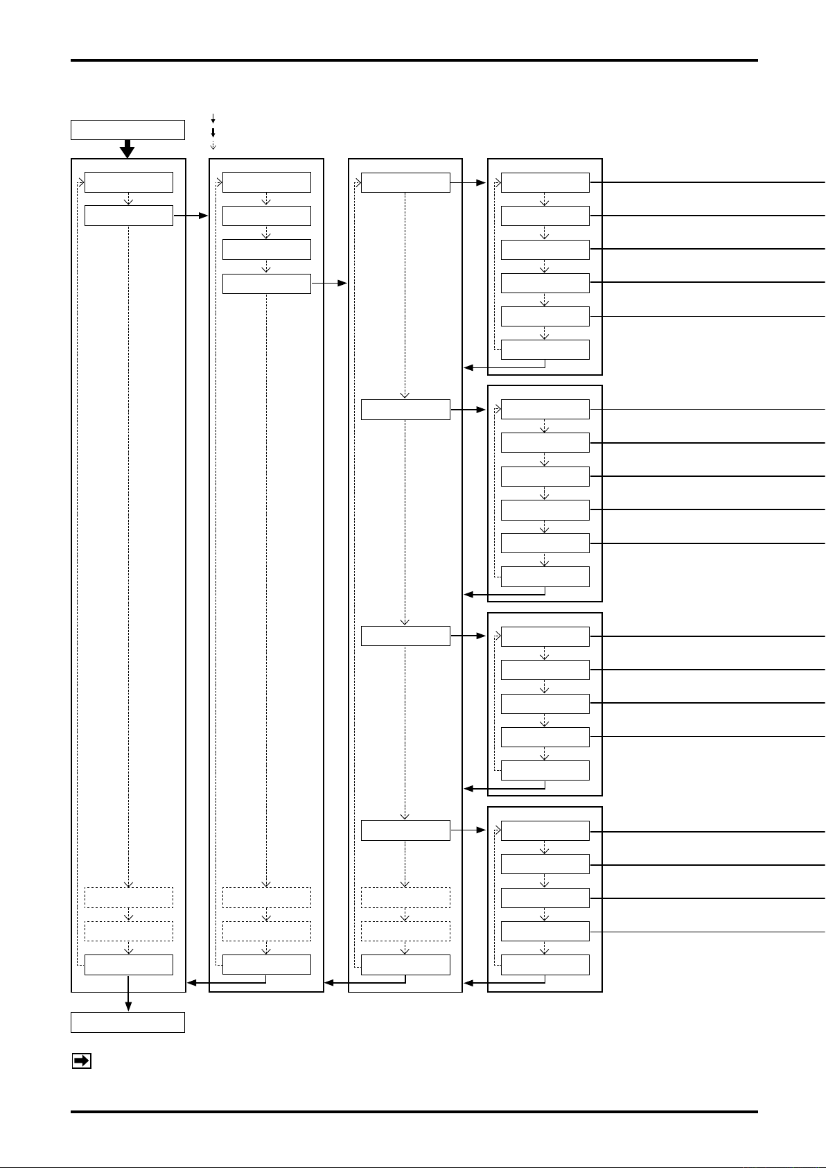
L-737-3-E
9.2.4 Transition chart of view (3)
MODE SELECT
: "SEL1" operation
: "SEL3" operation (For operating procedure, see 9.1.2 Switching operation.)
: "ENT" operation
1.Password & Disp
2.Setup
※1
1.Flow Param
2.Den Param
3.Temp Param
4.Outputs
1.Ana. Output1
2.Ana. Output2
1.Assign
2.URV
3.LRV
4.Lowcut
5.Added Damp
Exit
1.Assign
2.URV
3.LRV
4.Lowcut
5.Added Damp
Exit
3.Diag/Service
4.Maintenance
Exit
Process screen
5.Status Input
6.H/L Alarm
Exit
3.Pls. Output1
4.Pls. Output2
5.Status Output
6.Error Output
Exit
1.Assign
2.Freq Factor
3.Rate Factor
4.Lowcut
Exit
1.Assign
2.Freq Factor
3.Rate Factor
4.Lowcut
Exit
40
NOTE:
※1:For this function, the setting change is disabled in Write Protect mode (refer to section 9.2).
Page 41
L-737-3-E
No. Item Description Setup Default
2-4-1-1 Assign
2-4-1-2 URV
2-4-1-3 LRV
2-4-1-4 Lowcut
2-4-1-5 Added Damp
No. Item Description Setup Default
2-4-2-1 Assign
2-4-2-2 URV
2-4-2-3 LRV
2-4-2-4 Lowcut
2-4-2-5 Added Damp
Changes analog output 1 assignment. (See 9.13 Analog Output Function.)
If assignment is changed, reconfigure upper limit [No. 2-4-1-2], lower limit [No. 2-4-1-3], low cutoff [No. 2-41-4], and damping factor [No. 2-4-1-5] for optimum settings.
Changes analog output 1 upper limit. A 20mA output is produced at the value so set.
A value smaller than lower limit [No. 2-4-1-3] and a value larger than max. allowable range are not
acceptable.
Changes analog output 1 lower limit. A 4mA output is produced at the value so set.
A value larger than upper limit [No. 2-4-1-2] and a value larger than the max. allowable range are not
acceptable.
Changes analog output 1 low cutoff (%).
When low flow cutoff is greater than proportion of analog output where upper limit [No. 2-4-1-2] is set at
100% and lower limit [No. 2-4-1-3] at 0%, analog output is clamped at 4mA.
Changes analog output 1 damping factor (sec).
If analog output 1 fluctuates excessively, select a larger value; if fast response is desired, select a smaller
value.
Changes analog output 2 assignment. (See 9.13 Analog Output Function.)
If assignment is changed, reconfigure upper limit [No. 2-4-2-2], lower limit [No. 2-4-2-3], low cutoff [No. 2-42-4], and damping factor [No. 2-4-2-5] for optimum settings.
Changes analog output 2 upper limit. A 20mA output is produced at the value so set.
A value smaller than lower limit [No. 2-4-2-3] and a value larger than the max. allowable range are not
acceptable.
Changes analog output 2 lower limit. A 4mA output is produced at the value so set.
A value larger than upper limit [No. 2-4-2-2] and a value larger than the max. allowable range are not
acceptable.
Changes analog output 2 low cutoff (%).
When low flow cutoff is greater than proportion of analog output where upper limit [No. 2-4-2-2] is set at
100% and lower limit [No. 2-4-2-3] at 0%, analog output is clamped at 4mA.
Changes analog output 2 damping factor (sec).
If analog output 2 fluctuates excessively, select a larger value; if fast response is desired, select a smaller
value.
See 9.4 Mass Flow
See 9.3 180.000
See 9.3 0.00000
See 9.3 0.0
See 9.3 0.0
See 9.4 Mass Flow
See 9.3 180.000
See 9.3 0.00000
See 9.3 0.0
See 9.3 0.0
No. Item Description Setup Default
2-4-3-1 Assign
2-4-3-2 Freq Factor
2-4-3-3 Rate Factor
2-4-3-4 Lowcut
No. Item Description Setup Default
2-4-4-1 Assign
2-4-4-2 Freq Factor
2-4-4-3 Rate Factor
2-4-4-4 Lowcut
Changes pulse output 1 assignment. (For functions, see 9.12 Pulse Output Function.)
If assignment is changed, reconfigure frequency at full scale [No. 2-4-3-2], full scale flowrate [No. 2-4-3-3],
and low cutoff [No. 2-4-3-4] for optimum settings.
Changes the max. frequency of pulse output 1. An output is produced at the frequency (duty 50%) set at
full scale [No. 2-4-3-3]. Set up to match the measuring frequency range of instrument used for pulse output
measurement.
Changes pulse output 1 full scale flowrate.
An output is produced at the max. frequency [No. 2-4-3-2] when preset flowrate is reached.
Changes low cutoff (%) of pulse output 1.
When proportion of flowrate falls below low cutoff where full scale flowrate [No. 2-4-3-3] is set at 100%, the
pulse output is clamped at 0.
Changes pulse output 2 assignment. (For functions, see 9.12 Pulse Output Function.)
If assignment is changed, reconfigure frequency at full scale [No. 2-4-4-2], full scale flowrate [No. 2-4-4-3],
and low cutoff [No. 2-4-4-4] for optimum settings.
Changes the max. frequency of pulse output 2. An output is produced at the frequency (duty 50%) set at full
scale rate [No. 2-4-4-3]. (If double pulse output is your option at pulse output 2 assignment [No. 2-4-4-1],
this setting becomes invalid, however.)
Changes pulse output 2 full scale flowrate. An output is produced at max. freq. [No. 2-4-4-1] when preset
rate is reached. (If double pulse output is your option at pulse output 2 assignment [No. 2-4-4-1], this setting
becomes invalid, however.)
Changes pulse output 2 low cutoff (%).
When proportion of flowrate falls below low cutoff where full scale flowrate [No. 2-4-3-3] is set at 100%, the
pulse output is clamped at 0 (zero).
See 9.4 Mass Flow
See 9.3 1000.0
See 9.3 180.000
See 9.3 0.0
See 9.4 Mass Flow
See 9.3 1000.0
See 9.3 180.0
See 9.3 0.0
41
Page 42
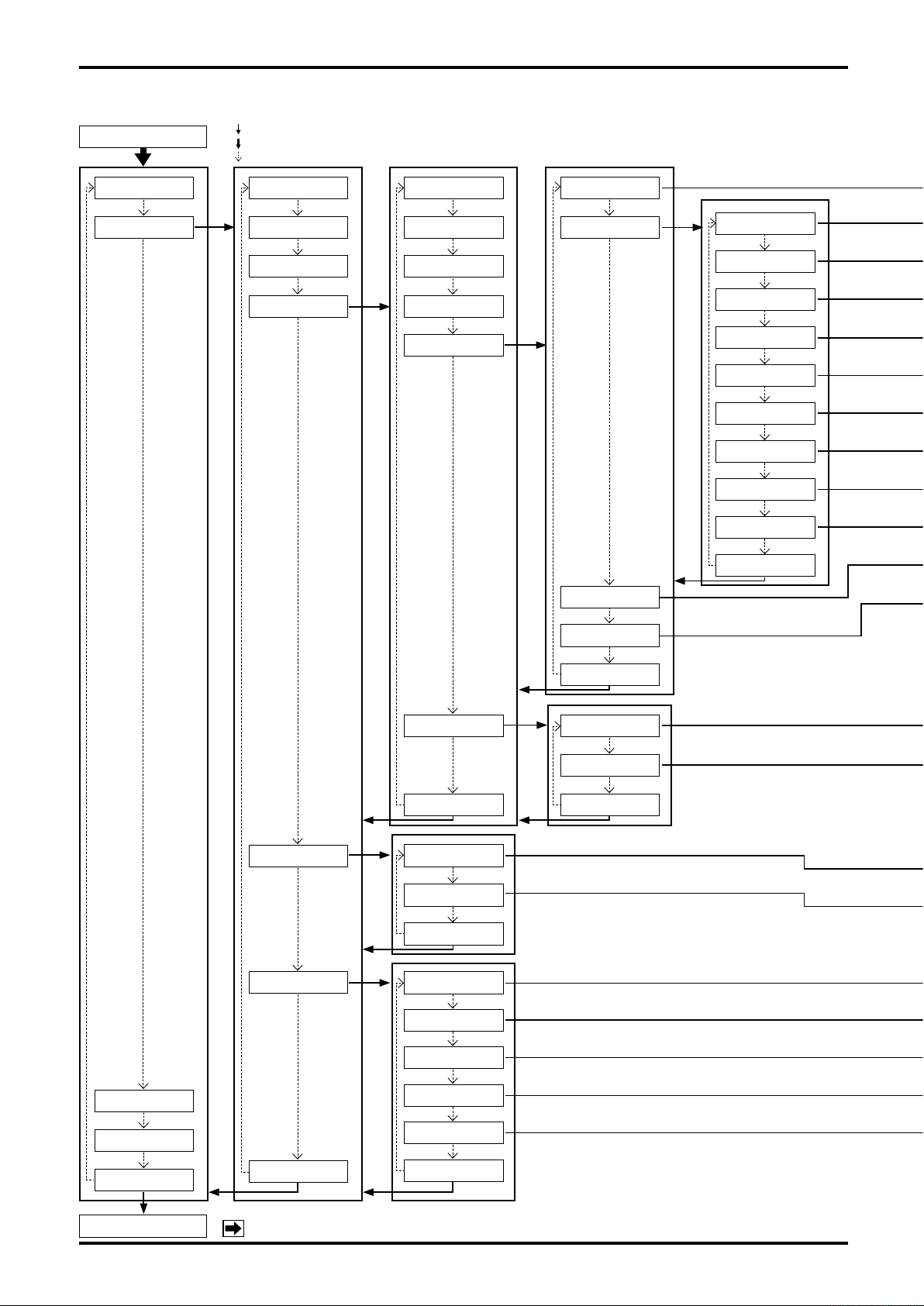
L-737-3-E
9.2.5 Transition chart of view (4)
MODE SELECT
1.Password & Disp
2.Setup
: "SEL1" operation
: "SEL3" operation (For operating procedure, see 9.1.2 Switching operation.)
: "ENT" operation
1.Flow Param
2.DensParam
※1
3.Temp Param
4.Outputs
1.Ana. Output1
2.Ana. Output2
3.Pls. Output1
4.Pls. Output2
5.Status Output
1.Function
2.Select
1.Sensor Fail
2.Txr Fail
3.Cal Fail
4.Satura. Alm.
5.Param Alm.
6.Txr Alm.
7.Slug Alm.
8.Cal in prog.
9.Fix Output
5.Status Input
6.H/L Alarm
6.Error Output
Exit
1.Function
2.Mode
Exit
1.Assign
3.Drive Output
4.Mode
Exit
1.Analog
2.Pulse
Exit
Exit
Po.
3.Diag/Service
4.Maintenance
Exit
Process screen
42
Exit
NOTE:
2.H/L Alm. Type
3.High Alm. Po.
4.Low Alm. Po.
5.H/L Alm. hys
Exit
※1:For this function, the setting change is disabled in Write Protect mode (refer to section 9.2).
Page 43
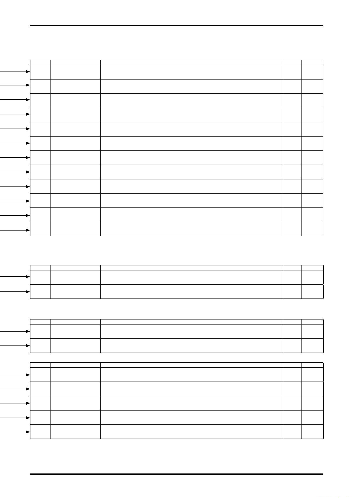
L-737-3-E
No. Item Description Setup Default
2-4-5-1 Function Changes status output assignment. (For detail, see 9.14 Status Output Function.) See 9.4
2-4-5-2-1 Sensor Fail
2-4-5-2-2 Txr Fail
2-4-5-2-3 Cal Fail
2-4-5-2-4 Satura. Alm.
2-4-5-2-5 Param Alm.
2-4-5-2-6 Txr Alm.
2-4-5-2-7 Slug Alm.
2-4-5-2-8 Cal in prog.
2-4-5-2-9 Fix Output
2-4-5-3 Drive Output Po. The threshold value of a drive output can be set up. See 9.4 100
1: Off ⇒ No assignment to status output, 2: On ⇒ Sensor Fail state is assigned to status output.
No output appears unless Status Out is selected at status output function assignment [No. 2-4-5-1],
however. For detail of Sensor Fail, see 10.1 Error Messages.
1: Off ⇒ No assignment to status output, 2: On ⇒ Txr Fail state is assigned to status output.
No output appears unless Status Out is selected at status output function assignment [No. 2-4-5-1],
however. For detail of Txr Fail, see 10.1 Error Messages.
1: Off ⇒ No assignment to status output, 2: On ⇒ Calibration Fail state is assigned to status output.
No output appears unless Status Out is selected at status output function assignment [No. 2-4-5-1],
however. For detail of Calibration Fail, see 10.1 Error Messages.
1: Off ⇒ No assignment to status output, 2: On ⇒ Saturated alarm state is assigned to status output.
No output appears unless Status Out is selected at status output function assignment [No. 2-4-5-1],
however. For detail of Saturation alarm, see 10.1 Error Messages.
1: Off ⇒ No assignment to status output, 2: On ⇒ Parameter alarm state is assigned to status output.
No output appears unless Status Out is selected at status output function assignment [No. 2-4-5-1],
however. For detail of Parameter alarm, see 10.1 Error Messages.
1: Off ⇒ No assignment to status output, 2: On ⇒ Txr alarm state is assigned to status output.
No output appears unless Status Out is selected at status output function assignment [No. 2-4-5-1],
however. For detail of Txr alarm, see 10.1 Error Messages.
1: Off ⇒ No assignment to status output, 2: On ⇒ Slug alarm state is assigned to status output.
No output appears unless Status Out is selected at status output function assignment [No. 2-4-5-1],
however. For detail of Slug alarm, see 10.1 Error Messages.
1: Off ⇒ No assignment to status output, 2: On ⇒ Cal in Progress state is assigned to status output.
No output appears unless Status Out is selected at status output function assignment [No. 2-4-5-1],
however. For detail of Cal in Progress, see 10.1 Error Messages.
1: Off ⇒ No assignment to status output, 2: On ⇒ Fix output state is assigned to status output.
No output appears unless Status Out is selected at status output function assignment [No. 2-4-5-1],
however. For detail of Fix output, see 10.1 Error Messages.
Error
Status
See 9.4 Off
See 9.4 Off
See 9.4 Off
See 9.4 Off
See 9.4 Off
See 9.4 Off
See 9.4 On
See 9.4 Off
See 9.4 Off
2-4-5-4 Mode
No. Item Description Setup Default
2-4-6-1 Analog
2-4-6-2 Pulse
No. Item Description Setup Default
2-5-1 Function Changes status input assignment. (See 9.15 Status input functions.) See 9.4 No function
2-5-2 Mode
No. Item Description Setup Default
2-6-1 Assigh
2-6-2 H/L Alm. Type
2-6-3 High Alm. Po.
2-6-4 Low Alm. Po.
2-6-5 H/L Alm. hys
1: Off Active⇒With Status output condition "ON", status output is turned off.
2: On Active⇒With Status output condition "ON", status output is turned on.
Selects analog output pattern when an alarm condition occurs (sensor failure, Txr failure, or parameter alarm).
1: Downscale ⇒ Produces 2.4mA, 2: Zero ⇒ Produces 4mA, 3: Hold ⇒ Produces analog value as it is in
an error, 4: Upscale ⇒ Produces 21.6mA.
Selects pulse output pattern in an error (sensor failure, Txr failure, or parameter alarm).
1: Zero ⇒ Stops pulse output, 2: Hold ⇒ Produces pulse output value as it is in an error,
3: Upscale ⇒ Produces an 11kHz output.
Selects status input operating conditions.
1: Short Active ⇒ Means that status input is shorted and action begins.
2: Open Active ⇒ Means that status input is open and action begins.
Changes H/L alarm assignment. (See 9.16 High low alarm functions.)
To validate this setting, it is necessary that H/L alarm be selected at status output assignment.
Selects type of H/L alarm.
1: High alarm ⇒ High alarm is active, 2: Low alarm ⇒ Low alarm is active,
3: H/L alarm ⇒ Both high and low alarms are active.
Changes high alarm setting. A value exceeding this setting activates high alarm; when it falls below this
setting by H/L alarm hysteresis [No. 2-6-5], high alarm condition is reset. A setting smaller than low alarm
[No. 2-6-4] is not acceptable.
Changes low alarm setting. A value falling below this setting activates low alarm; when it exceeds this
setting by H/L alarm hysteresis ]No. 2-6-5], low alarm condition is reset. A setting smaller than high alarm
[No. 2-6-3] is not acceptable.
Changes high/low alarm hysteresis setting. Frequent annoying false alarms (repetitive alarm on/off in short
duration) can be alleviated by choosing a larger value. To get an accurate picture of alarm condition, choose
a smaller value.
See 9.4 Off Active
See 9.4 Downscale
See 9.4 Zero
See 9.4
Short Active
See 9.4 Mass Flow
See 9.4 High Alarm
See 9.3 0.0
See 9.3 0.0
See 9.3 0
43
Page 44
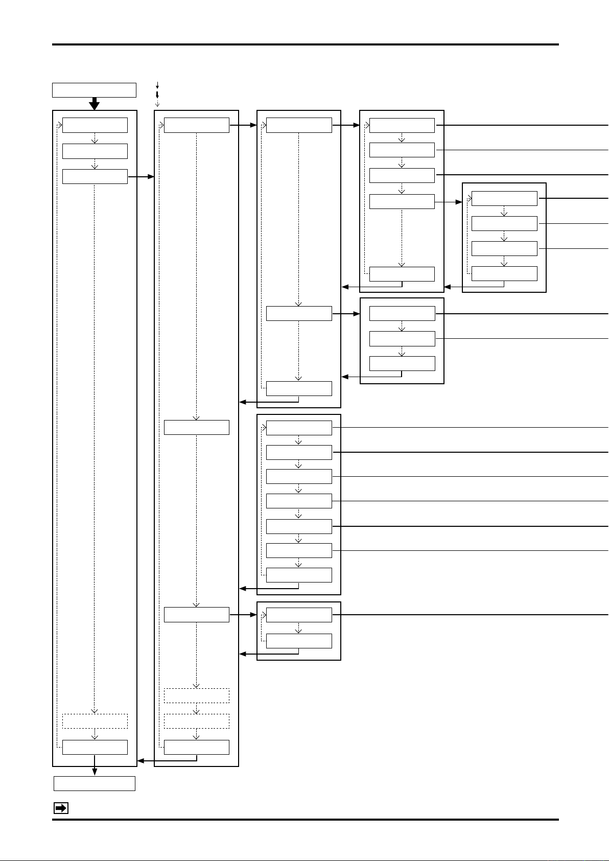
L-737-3-E
9.2.6 Transition chart of view (5)
MODE SELECT
: "SEL1" operation
: "SEL3" operation (For operating procedure, see 9.1.2 Switching operation.)
: "ENT" operation
1.Password & Disp
2.Setup
3.Diag/Service
1.Test/Status 1.Self-Diag
2.Installation
Exit
1.Hardware
2.
Drive coil Check
3.Txr Condition
4.LCD Test
Exit
1.Static
2.Dynamic
Exit
1.Back Light
2.LED
3.LCD
Exit
4.Maintenance
2.Loop Test
3.Calibration
4.Trim Analog
5.Cnt/Ttl Reset
1.Fix Analog1
2.Fix Analog2
3.Fix Pulse1
4.Fix Pulse2
5.Status Output
6.Status Input
Exit
1.Auto Zero
Exit
※1
Exit
Process screen
NOTE:
44
Exit
※1:This function is disabled in Write Protect mode (refer to section 9.2).
Page 45
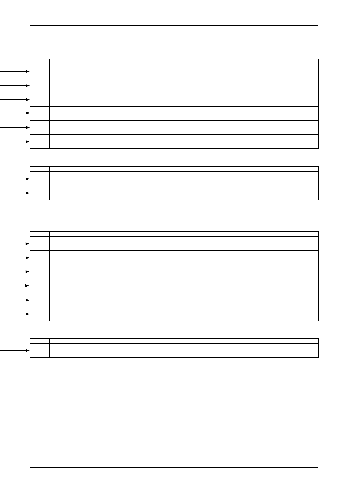
L-737-3-E
No. Item Description Setup Default
3-1-1-1 Hardware
3-1-1-2 Drive coil Check
3-1-1-3 Txr Condition
3-1-1-4-1 Back Light
3-1-1-4-2 LED
3-1-1-4-3 LCD
No. Item Description Setup Default
3-1-2-1 Static
3-1-2-2 Dynamic
Runs a check for possible problems in the probe.
For details, see 9.6.1 Probe check.
CAUTION: Be very careful as this check can stop outputs under certain circumstances.
Runs a check for an "open" in the drive coil.
For details, see 9.6.2 Drive coil check.
CAUTION: Be very careful as this check can stop outputs under certain circumstances.
Runs a check for possible problems in the transmitter.
For details, see 9.6.3 Transmitter check.
Tests backlight for possible problems by forcibly turning it on and off. While test continues, the LCD remains dead.
Performance test consist of WHT backlight lit (3 sec), ORG backlight lit (3 sec) and backlight unlit (3 sec) conducted
twice one after the other (total of 18 sec) and ends automatically. After the test, the LCD restores normal illumination.
Tests LEDs for possible problems by forcibly turning them on and off. While test continues, the LCDs remain
dead. Performance test consist of RED LED lit (1.5 sec) and GRN LED lit (1.5 sec) conducted 6 times
alternately (total of 18 sec) and ends automatically. After the test, the LCDs restore normal illumination.
Tests LCD for possible problems by illuminating and extinguishing all LCD dots. While test continues, the LCDs are
forcibly switched in and out. Performance test consist of all dots lit (3 sec) and all dots unlit (3 sec) conducted twice
alternately and ends automatically (a total of 12 sec). After the test, the LCDs restore normal illumination.
Runs a check for stability of sensor signal at zero flow.
For details, see 9.6.4 Pipeline oscillation check (zero flow).
Runs a check for stability of sensor signal while allowing the fluid.
For details, see 9.6.5 Pipeline oscillation check (fluid flowing).
See 9.6.1 —
See 9.6.2 —
See 9.6.3 —
See 9.4 —
See 9.6.4
See 9.6.5
—
—
—
—
No. Item Description Setup Default
3-2-1 Fix Analog1
3-2-2 Fix Analog2
3-2-3 Fix Pulse1
3-2-4 Fix Pulse2
3-2-5 Status Output
3-2-6 Status Input
No. Item Description Setup Default
3-3-1 Auto Zero
Produces a simulated output of analog output 1. It is beneficial for testing cable fault and performance of
associated equipment.
For details, see 9.7.1 Analog output.
Produces a simulated output of analog output 2. It is beneficial for testing cable fault and performance of
associated equipment.
For details, see 9.7.1 Analog output.
Produces a simulated output of pulse output 1. It is beneficial for testing cable fault and performance of
associated equipment.
For details, see 9.7.2 Pulse output.
Produces a simulated output of pulse output 2. It is beneficial for testing cable fault and performance of
associated equipment.
For details, see 9.7.2 Pulse output.
Produces a simulated output of status output. It is beneficial for testing cable fault and performance of
associated equipment.
For details, see 9.7.3 Status output.
Monitors status input. It is beneficial for testing cable fault and performance of associated equipment.
For details, see 9.7.4 Status monitor input.
Performs zeroing. When you perform zeroing, verify that the flow is at zero.
For details, see 9.8 Zeroing Function.
See 9.7.1 —
See 9.7.1 —
See 9.7.2 —
See 9.7.2 —
See 9.7.3 —
See 9.7.4 —
See 9.8 —
45
Page 46
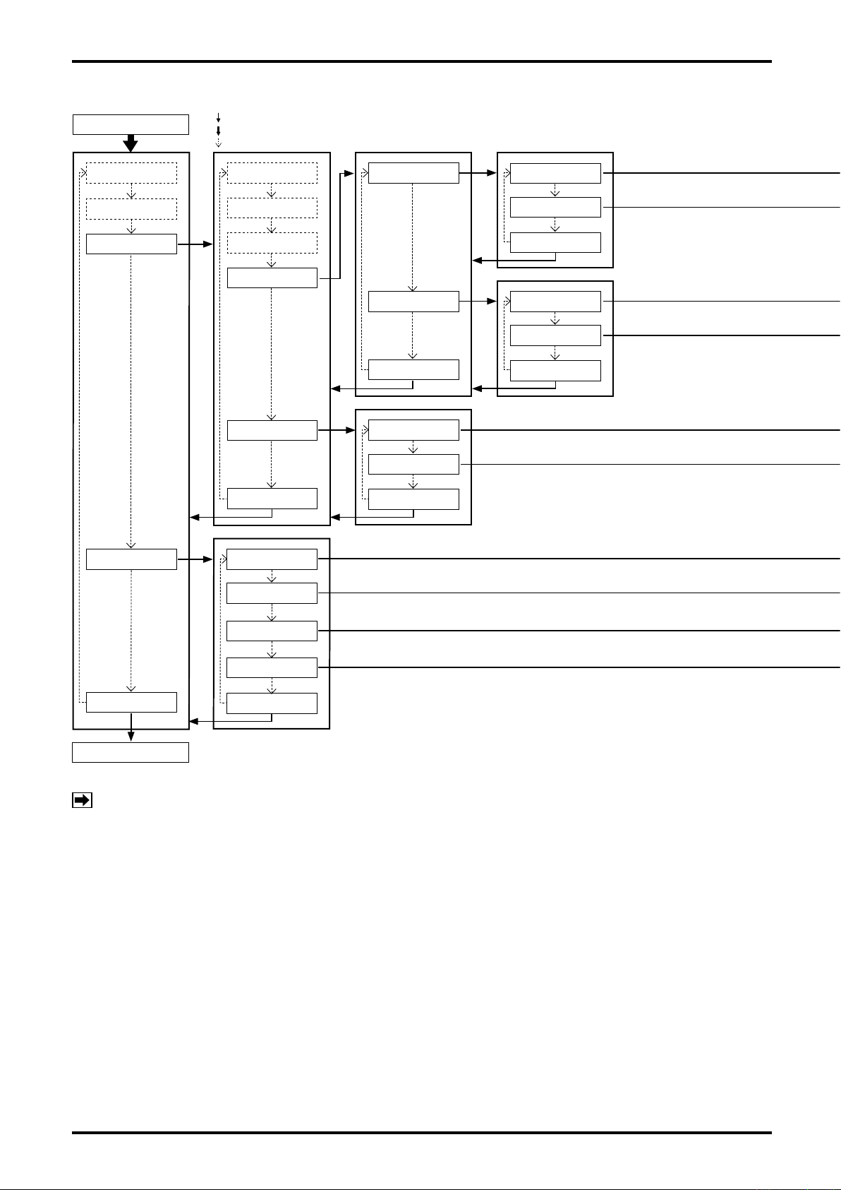
L-737-3-E
9.2.7 Transition chart of view (6)
MODE SELECT
1.Password & Disp
2.Setup
3.Diag/Service
: "SEL1" operation
: "SEL3" operation (For operating procedure, see 9.1.2 Switching operation.)
: "ENT" operation
1.Test/Status 1.Trim Analog1
2.Loop Test
3.Calibration
4.Trim Analog
5.Cnt/Ttl Reset
Exit
※1
※1
2.Trim Analog2
Exit
1.Count/Total1
2.Count/Total2
Exit
1.4mA
2.20mA
Exit
1.4mA
2.20mA
Exit
4.Maintenance
Exit
Process screen
NOTE:
※1:This function is disabled in Write Protect mode (refer to section 9.2).
1.Input Signals
2.View History
3.Telop Info.
4.Soft Version
Exit
46
Page 47
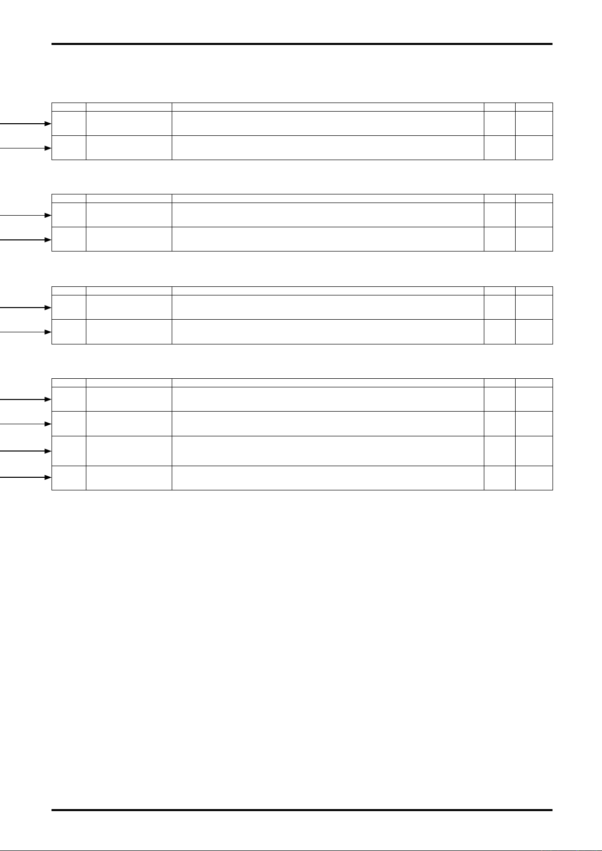
L-737-3-E
No. Item Description Setup Default
3-4-1-1 4mA
3-4-1-2 20mA
No. Item Description Setup Default
3-4-2-1 4mA
3-4-2-2 20mA
No. Item Description Setup Default
3-5-1 Count/Total1
3-5-2 Count/Total2
No. Item Description Setup Default
4-1 Input Signals The screen is used for maintenance. View only —
Trims 4mA analog output 1. It is factory adjusted and normally further adjustment is not required.
However, if it is absolutely necessary, follow the procedure outlined.
For details, see 9.9 Analog Output Trim.
Trims 20mA analog output 1. It is factory adjusted and normally further adjustment is not required.
However, if it is absolutely necessary, follow the procedure outlined.
For details, see 9.9 Analog Output Trim.
Trims 4mA analog output 2. It is factory adjusted and normally further adjustment is not required.
However, if it is absolutely necessary, follow the procedure outlined.
For details, see 9.9 Analog Output Trim.
Trims 20mA analog output 1. It is factory adjusted and normally further adjustment is not required.
However, if it is absolutely necessary, follow the procedure outlined.
For details, see 9.9 Analog Output Trim.
Resets counter 1 and totalizer 1 reading to 0.
For details, see 9.10 Reset Function.
Resets counter 2 and totalizer 2 reading to 0.
For details, see 9.10 Reset Function.
See 9.9 —
See 9.9 —
See 9.9 —
See 9.9 —
See 9.10 —
See 9.10 —
4-2 View History
4-3 Telop Info.
4-4 Soft Version Shows the software version and checksum value. Vrew only —
Shows the number of running hours of transmitter.
Can be switched to calendar view. (Incorporated clock is maintenance oriented; No updating takes place if
power to the transmitter is interrupted.)
When the number of running hours exceeds 100,000, a black circle "●" begins to blink at lower left of LCD
which can be canceled.
1: Off ⇒ "●" stays off irrespective of elapsed hours. 2: ON ⇒ warning "●" begins to blink after 100,000
hours.
See 9.4 ON
—
47
Page 48
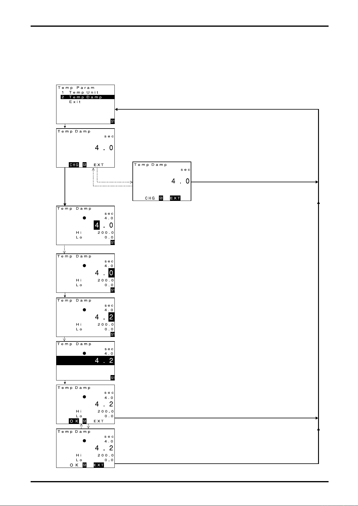
L-737-3-E
9.3 Parameter Value Entry
The procedure to enter a numerical data of parameters is described here. As an example, reconfiguring
the temperature damping factor from "4.0" to "4.2" is covered in this section. A similar procedure applies
to setting up other parameters.
(1) Bring up the parameter item subject to setup.
Operate the view until the desired item subject to setup appears.
(For the procedure to view individual items, see 9.2.2 thru 9.2.7 Transition chart.)
When the cursor is moved and located at the desired item, click "SEL1" to bring up the
temperature damping factor setup screen.
Click "SEL1".
Click "SEL3". Click "ENT"
Click "ENT".
Click "ENT" twice.
Click "SEL1" twice.
(2) Decide whether to modify this parameter or not.
Current setting is shown. If you want to modify it, click "SEL 3" to proceed to the next
screen.
If the current setting is OK, click "ENT" and then "SEL3" to return to the menu select
screen.
Click "SEL3".
(3) Numerical data adjustment
To move the cursor to the right, click "ENT".
(As scroll continues, a click next to the rightmost digit brings up a numerical data field
where all digits are highlighted [decision window]; clicking "ENT" further brings the cursor
to the leftmost digit.)
To increment the number, click "SEL1". To continually increment the number, hold "SEL1".
(The number changes in the order "0" ⇒ "1" ⇒ "2" ⇒ "3" ⇒ "4" ⇒ "5" ⇒ "6" ⇒ "7" ⇒" 8"
⇒ "9" ⇒ "." ⇒ "-" ⇒ " ".)
① Move the cursor to the digit of interest.
With a change from "4.0" to "4.2" in mind, move the cursor to the 1st decimal place subject
to data adjustment.
Click "ENT" twice. (The next screen appears.)
② Adjust the numerical value.
With a change from "4.0" to "4.2" in mind, adjust the number in the 1st decimal place from
"0" to "2".
Click "SEL1" twice. (The next screen appears.)
③ Bring up the state ready to finalize numerical value entry.
Click "ENT", readying for finalizing the entry.
(The next screen appears.)
48
Click "ENT" once.
Click "SEL1".
Click "ENT". Click "ENT".
④ Finalize the entry.
Confirm that the desired numerical value is indicated.
Click "SEL1" readying for final confirmation of entry.
(The next screen appears.)
(4) Activate the data entry.
① If the setting "4.2" is definitely OK, click "SEL3".
Setting is now complete. The previous data 4.0 is replaced by 4.2 and the window
returns to the initial menu select screen.
If you want to abort the setting process, click "ENT". (The next screen appears.)
Click "SEL3".
② If you want to abort the setting process, click "SEL3".
A numerical value "4.0" remains unchanged and the window returns to the initial menu
select screen.
Click "SEL3".
Page 49
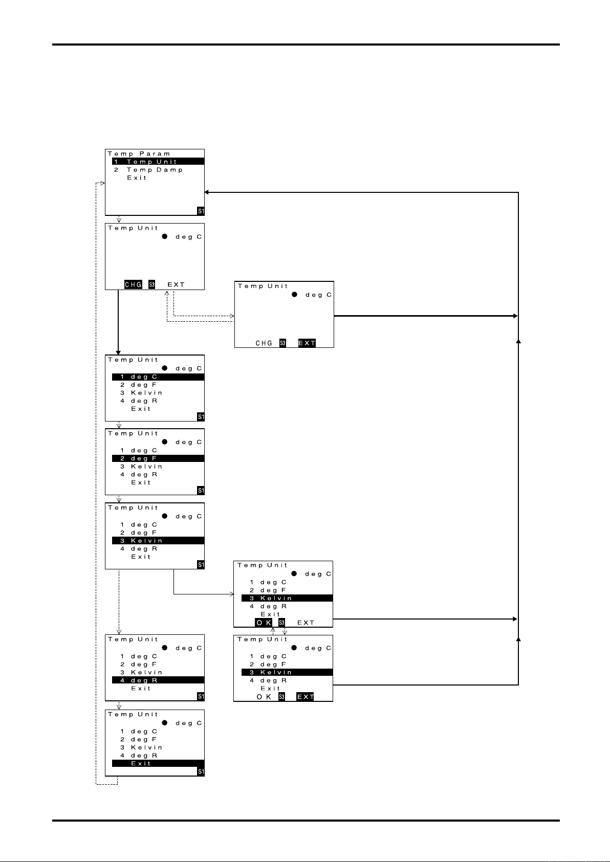
L-737-3-E
9.4 Parameter Selection
The procedure to select a menu item of parameters is described here. As an example, selecting "Kelvin"
in temperature unit setting is covered in this section. A similar procedure applies to setting up other
parameters.
(1) Bring up the parameter item to be configured.
Operate the view until the desired menu item to be set up appears.
(For the procedure to view individual items, see 9.2.2 thru 9.2.7 Transition chart.)
Move the cursor to the desired item, operate "SEL 1" to bring up temperature unit setup
screen.
Click "SEL1".
Click "SEL3".
Click "ENT".
Click "ENT".
Click "ENT".
Click "ENT".
(2) Decide whether to change this parameter or not.
If you want to modify the current parameter shown, operate "SEL 3" to proceed to
the next screen.
If the current setting is acceptable, click "ENT" and "SEL 3" to return to the menu
select screen.
Click "SEL3".
(3) A change in option select screen
① Click "ENT" twice to select the desired item (Kelvin).
(To continue scrolling, hold down "ENT" key.)
② Confirm that the desired item (Kelvin) is selected.
To activate this setting (Kelvin), click "SEL 1".
To abort setting, click "ENT" twice and select Exit.
Click "ENT".
Click "ENT".
Click "ENT".
(4) Finalizing the menu item.
① If the setting (Kelvin) is O.K., operate "SEL 3".
Setting is complete and it returns to the initial
menu select screen.
To abort setting, click "ENT" twice. (The screen
below appears.)
Click "SEL3".
② To abort setting, click "SEL 3".
The unit remains unchanged and it returns to
the initial menu select screen.
To abort setting, click "ENT". (Next screen
appears.)
Operate "SEL3".
③ If it is desired to exit the unit select screen. click "ENT".
The window returns to the initial menu select screen.
49
Page 50
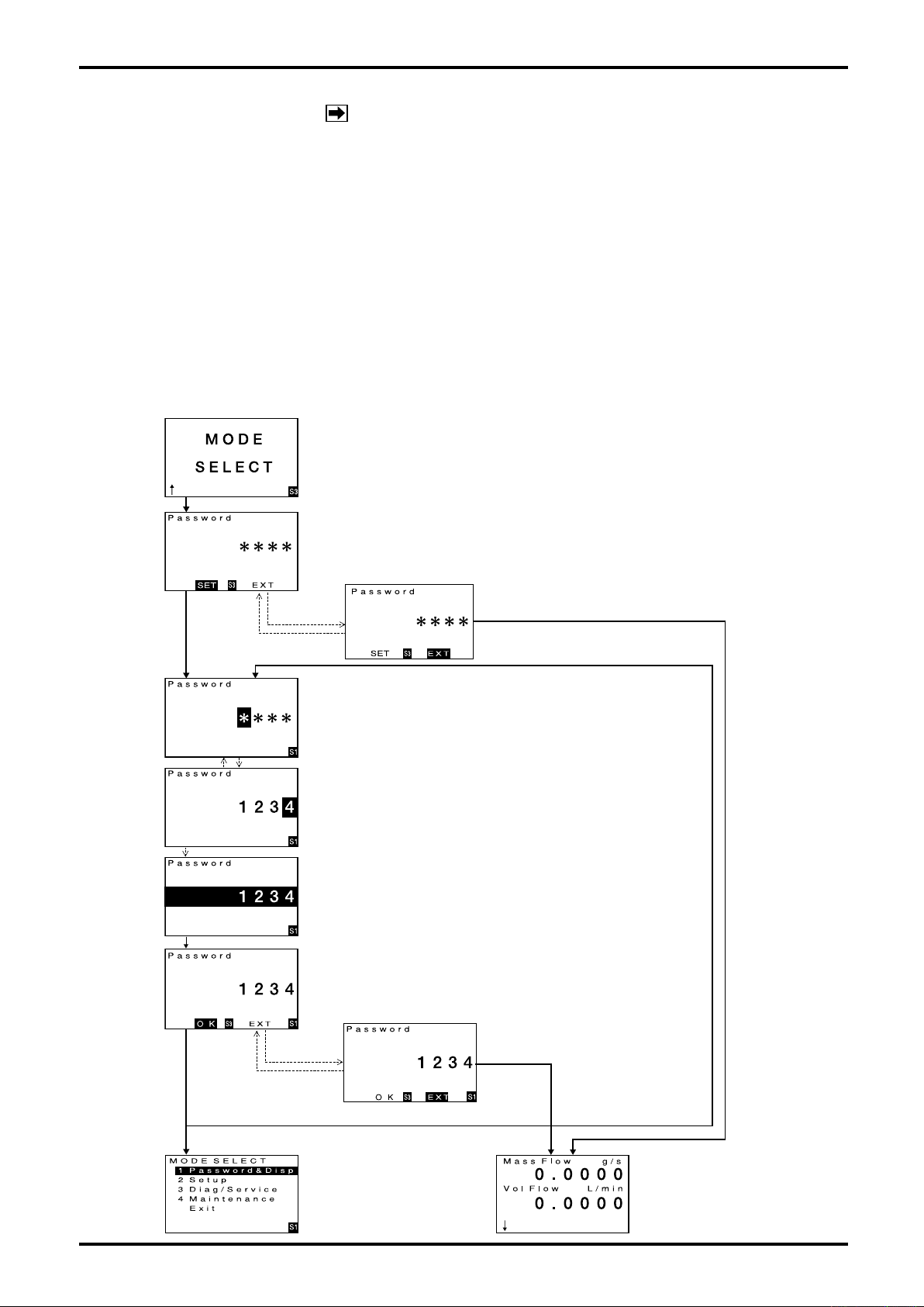
L-737-3-E
9.5 Password Function
NOTE:
For this function, the setting change is disabled in Write
Protect mode (refer to section 9.2).
To safeguard transmitter signals and readings against unauthorized parameter modification, you can
configure the transmitter to request entering a password before bringing up the configuration screen.
9.5.1 Password function setup
To enable the password function, it is necessary that the following items be set up.
(1) Password function setting (Password Set) (See 9.2.2 Transition chart and description (1) [No. 1-1].)
To activate password function, select "ON" ; to deactivate it, select "OFF".
(2) Creating a password (Password) (See 9.2.2 Transition chart and Description (1) [No. 1-2].)
Enter a 4-digit login password of numerals.
Once these setting are activated, entering a password is asked before any request for password
modification. Use extra care in the setup process because if the user forgets his password, there
will be no way to get to the reconfiguration screen.
(1) Bring up "MODE SELECT" screen.
Repeat clicking "EXT" until "MODE SELECT" screen appears.
("MODE SELECT" screen is shown at left.)
(2) Proceed key operation to enter the setup sreen.
Click "SEL3" and the password setup screen appears.
Click "SEL3".
(3) Decide whether to enter a password or not.
To enter a password, click "SEL3" to proceed to the next screen.
To exist the password entry process, click "ENT" and then click "SEL3"
to return to the normal screen.
Click "SEL3". Click "ENT".
Click "ENT".
Click "ENT". Click "ENT".
Click "ENT".
Click "SEL1".
Click "SEL3".
Click "ENT".
Click "SEL3".
(4) Creating a password.
① Enter a numerical data.
Enter a password. (In the example at left, password is "1234".)
To increment the number, click "SEL1". To continually increment the
number, hold "SEL1". (Figure changes in the order "0" ⇒ "1" ⇒ "2" ⇒
"3" ⇒ "4" ⇒ "5" ⇒ "6" ⇒ "7" ⇒ "8" ⇒ "9".)
To move the cursor to the right, click "ENT". (As you scroll, a click next
to the rightmost digit brings up a numerical data field where all digits are
highlighted [decision window]; clicking "ENT" further brings the cursor to
the leftmost digit.)
② Bring up the state ready to finalize the numerical value entry.
(Next screen appears.)
A password value ("1234") is set up.
Click "ENT", readying for finalizing the entry.
(The next screen appears.)
③ Finalize the entry.
Click "SEL1". The numerical data is finalized and a confirmation screen
appears.
(The next screen appears.)
④ If "1234" in this password screen is definitely OK, press "SEL3".
If the password is valid, "MODE SELECT" menu screen appears.
If the password is invalid, a message "Input error" appears, bringing up
the password entry screen again.
To abort the setting process, press "ENT". (The next screen appears.)
⑤To terminate password entry, click
"SEL3" and the window returns to
the run screen.
50
*
Invalid password
*
Valid password
Click "ENT".
(5) Password entry is complete.
A setup menu view screen
appears.
Page 51
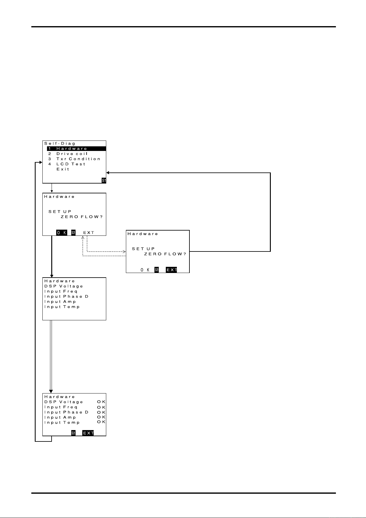
L-737-3-E
9.6 Self-diagnostic Capabilities
Comprehensive self diagnostic capabilities are incorporated in this transmitter. To derive the maximum
benefit from the instrument, make full use of these functions during maintenance and inspection for early
identification of trouble or for investigation of the causes of trouble in a fault condition.
9.6.1 Probe check
A diagnostic test can be conducted to see if the transmitter is free from any problem in the probe circuitry.
If an error is detected upon diagnosis, there is a possibility that it presents a risk to maintaining accurate
measurement. You are prompted to follow the instructions given at an NG sign.
(1) Bring up the item of function you want to use.
Firstly, scroll the menu downward until the probe check item (Hardware) appears. (For the
procedure to view individual items, see 9.2.2 thru 9.2.7 Transition chart.) When the cursor
is located at probe check (Hardware), press "SEL1" to bring up probe check start screen.
Click "SEL1".
(2) Decide whether to activate the function or not.
If running a probe check is desired, perform it at zero flow.
To start a probe check, click "SEL3" to proceed to the next screen.
If you want to end the operation without running a check, press "ENT"
and then click "SEL3". The window returns to the menu select screen.
Click "SEL3".
Results are indicated upon
completion of individual
checks.
Click "ENT".
Click "ENT".
Click "SEL3".
(3) Description of probe (hardware) check function.
Run a hardware check screen appears with test results to be indicated at right.
(During the check, GRN LED blinks on and off.)
When test is completed on all items, confirm the results at right. An "NG" indicates possible fault.
If such is the case, take corrective action below:
Corrective action in case of NG
DSP Voltage: A fault in internal power supply is suspected; contact the factory for repair.
Input Freq: A fault in the frequency counter. Run a drive coil check (see 9.6.2 Drive coil check).
If drive coil proves to be OK, a fault in circuitry is suspected; contact the factory.
Input Phase D: A fault in the phase difference measuring circuit. Run a transmitter check (see 9.6.3
Transmitter check). If it proves to be OK, a fault in the circuitry is suspected; contact the
factory.
Input Amp: A fault in the receiver circuit is suspected. Run a transmitter check (see 9.6.3 Transmitter
check). If it proves to be OK, a fault in the circuitry is suspected; contact the factory.
Input Amp: A fault in the temperature sensor. Run a transmitter check (see 9.6.3 Transmitter check).
If it proves to be OK, a fault in the circuitry is suspected; contact the factory.
(4) End of hardware check function
To terminate hardware check, press "SEL3".
Operation is brought to an end and the window returns to the initial menu select screen.
Click "SEL3".
51
Page 52
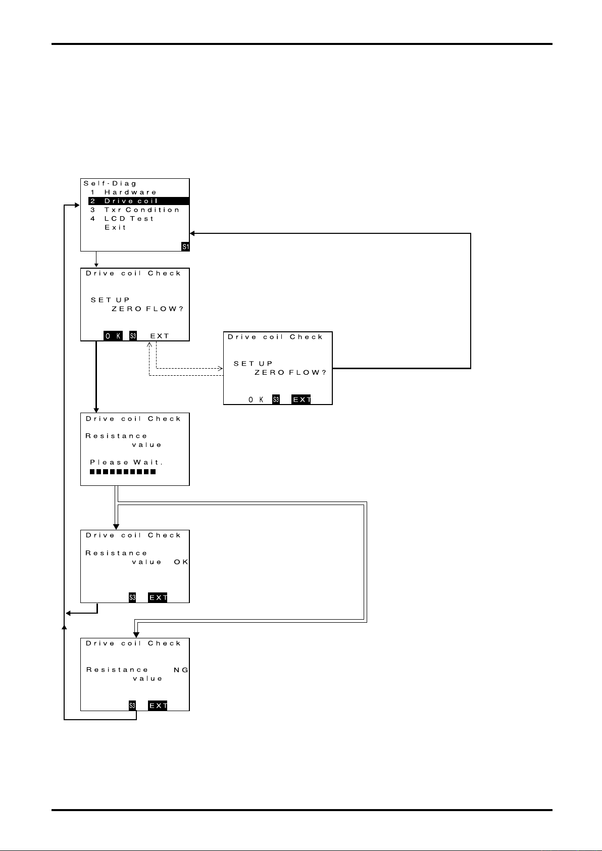
L-737-3-E
9.6.2 Drive coil check
A diagnostic test can be conducted to see if the drive coil is free from any problem. If an error is detected
upon diagnosis, there is a possibility that it presents a risk to maintaining accurate measurement. You are
prompted to follow the instructions given.
(1) Bring up the item of function you want to use.
Firstly, scroll the menu downward until drive coil check item appears.
(For the procedure to view individual items, see 9.2.2 thru 9.2.7 Transition
chart.)
When the cursor is located at Drive Coil check, click "SEL1" to bring up
Drive coil check start screen.
Click "SEL1".
(2) Decide whether to activate the function or not.
If running a drive coil check is desired, perform it at zero flow.
To start a drive coil check, click "SEL3" to proceed to the next screen.
If you want to end the check process without running a check, click
"ENT"and then click "SEL3". The window returns to the menu select
screen.
Click "SEL3". Click "ENT".
Click "ENT".
★
Proved acceptable
Click "SEL3".
Click "SEL3".
(3) Description of probe (hardware) check function.
Run Drive coil check screen appears and count down begins.
(The check lasts in 30 sec. approx.)
(During the check, GRN LED blinks on and off.)
★
Proved unacceptable
① Found to be OK
No problem is found in the drive coil.
To exit the drive coil check screen,
Click "SEL3".
Operation is brought to an end and the
window returns to the initial menu select
screen.
52
Click "SEL3".
② An error is detected in diagnostics
A problem is found in sensor connections.
Verify the sensor for correct connections.
If connections appear to be OK and yet erratic condition persists,
an open sensor is a possibility. Contact the factory.
To terminate the drive coil check process, click "SEL3".
Operation is brought to an end the window returns to the initial
menu select screen.
Page 53
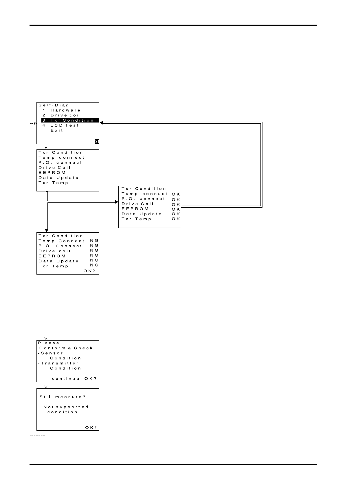
L-737-3-E
F a i l u r e
9.6.3 Transmitter check
A diagnostic test can be conducted to see if the transmitter is free from any problem. If an error is detected
upon diagnosis, there is a possibility that it presents a risk to maintaining accurate measurement. You are
prompted to follow the instructions given.
A precaution to remember: While the check is in progress, flowmetering is disabled with flowrate at 0
(zero).
(1) Bring up the item of function you want to use.
Firstly, scroll the menu downward until transmitter check (Txr Condition) appears.
(For the procedure to view individual items, see 9.2.2 thru 9.2.7 Transition chart.)
(2) Run the function
Place the cursor over transmitter check (Txr Condition) and click "SEL1".
Transmitter coil check begins and the next screen appears.
Click "SEL1".
★
(3) Description of transmitter check function
A check is conducted sequentially on individual items and results are
indicated at right.
(During the check, GRN LED blinks on and off.)
All items found OK
① Diagnostic results are OK.
No problem is found in the transmitter. A switch to menu select
screen takes place automatically.
★
Certain items found unusual.
Click "ENT".
Click "ENT".
② A problem is found in the diagnostic test.
A fault is in the transmitter.
Review the nature of item found to be NG and correct the conditions
according to the instructions below.
To exit the transmitter check process, click "ENT".
Corrective actions in case of NG
Temp. Connect: A fault is found in temperature sensor connections. Verify
sensor connections. (See 7. Wiring Connections.)
If erratic condition persists, contact the factory.
P.O.Connect: A fault is found in pickoff sensor connections. Verify sensor
connections. (See 7. Wiring Connections.)
If erratic condition persists, contact the factory.
EEPROM: Erratic data in EEPROM. A problem in operation is a
possibility; contact the factory. A problem in proper operation
is a possibility; contact the factory.
Date Update: Data error exists. A problem in proper operation is a
possibility; contact the factory.
Txr Temp: Internal temp. of transmitter is out of acceptable range;
continued operation in this condition will reduce life of parts.
Take necessary steps to lower temp.
If NG sign persists despite normal ambient temperature, a
defect in the transmitter is suspected; contact the factory.
③ A warning message upon detection of a fault.
To exit the transmitter check process, click "ENT".
④ A warning message upon detection of a fault.
The message tells the operator that correct measurement is no longer
warranted under the current conditions..
To exit the transmitter check process, click "ENT".
Operation is brought to an end and the window returns to the initial menu
select screen.
Click "ENT".
53
Page 54
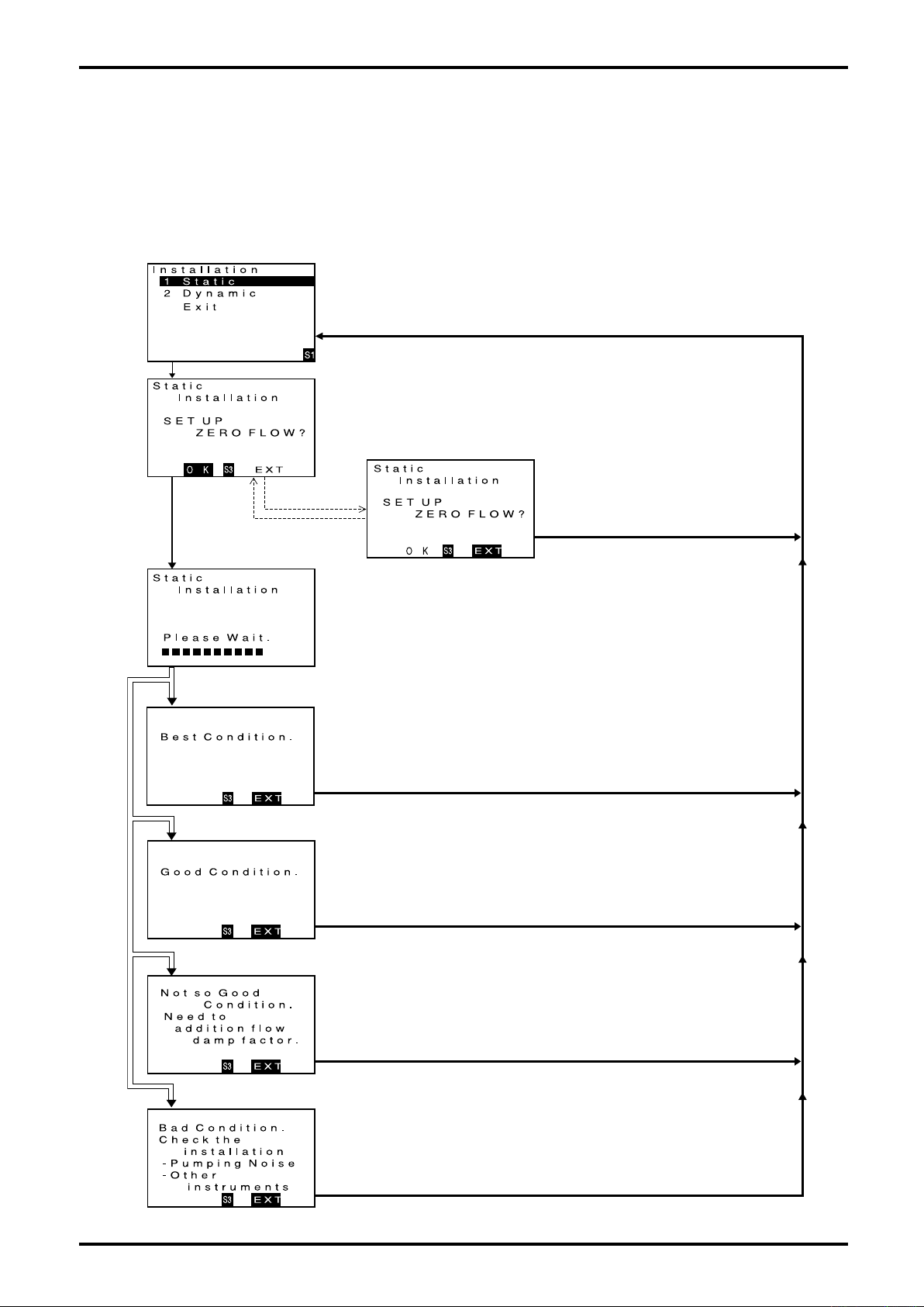
L-737-3-E
9.6.4 Pipeline vibration check (at zero flow)
This check diagnoses your flow measurement installation for condition - whether it is free from external
disturbances and noises resulting from pipeline vibration or other factors.
To be successful in obtaining accurate results, run the test at zero flow.
Upon completion of the check, diagnostic results will be indicated and you will be prompted to follow the
instructions given.
(1) Bring up the item of function you want to use.
Firstly, proceed key operation to show Installation (pipeline vibration check) (zero
flow) screen.
(For the procedure to view individual items, see 9.2.2 thru 9.2.7 Transition chart.)
When the cursor is placed over pipeline vibration check (Static), click "SEL1" to bring
up pipeline vibration check (Static) (zero flow) start screen.
Click "SEL1".
Click "SEL3". Click "ENT".
Click "ENT".
★
Best Condition
(2) Decide whether to activate the function or not.
If you want to run pipeline vibration check (Static) (zero flow), conduct it at zero
flow. To start Static check (zero flow), click "SEL3" to proceed to the next screen.
To exit the check process without running a check, click "ENT" and then click
"SEL3". The window returns to the menu select screen.
(3) Description of probe check function
Run pipeline vibration check (Static) (zero flow) start screen appears and count
down begins. (The check lasts in 30 seconds, approx.)
(During the check, GRN LED blinks on and off.)
(4) Diagnostic results
① Best Condition is indicated.
Top rated condition, permitting accurate and satisfactory measurement. Use the
meter in this state.
To end pipeline vibration check (Static) (zero flow) process, click "SEL3". Operation
is brought to an end and the window returns to the initial menu select screen.
Click "SEL3".
Click "SEL3".
54
★
Good Condition
★
Not so Good Condition
② Good Condition is indicated.
Sufficient for flow measurement. Use the meter in this state.
To end pipeline vibration check (Static) (zero flow) process, click "SEL3". Operation
is brought to an end and the window returns to the initial menu select screen.
Click "SEL3".
③ Not so Good Condition
Flow signal fluctuates. Verify influences of pump vibration or other disturbances.
To stabilize flow signal fluctuation, we suggest to select a larger damping factor for
the flow. To end pipeline vibration check (Static) (zero flow) process, click "SEL3".
Operation is brought to an end and the window returns to the initial menu select
Click "SEL3".
Click "SEL3".
screen.
④ Bad Condition
Flow signal fluctuates excessively.
Inspect the pipeline for condition. (See 6.4 Piping Instructions.)
Verify influences of pump vibration or other disturbances.
To stabilize flow signal fluctuation, we suggest to select a larger damping factor for
the flow. To end pipeline vibration check (Static) (zero flow) process, click "SEL3".
Operation is brought to an end and the window returns to the initial menu select
screen.
Page 55
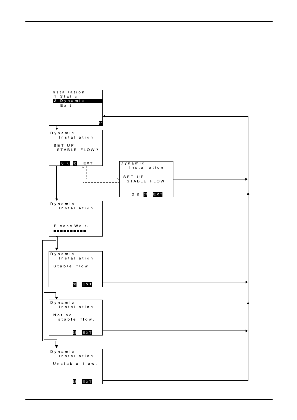
L-737-3-E
9.6.5 Pipeline oscillation check (at normal flow)
This check diagnoses your flow measurement installation for condition while allowing the fluid flow -
whether it is free from external disturbances and noises resulting from pipeline vibration or other factors.
Upon completion of the check, diagnostic results will be indicated and you will be prompted to follow the
instructions given.
During the process of diagnosis, analog output and pulse output operations are suspended.
(1) Bring up the item of function you want to use.
Firstly, proceed key operation to show Installation (pipeline vibration check) screen.
(For the procedure to view individual items, see 9.2.2 thru 9.2.7 Transition chart.)
When the cursor is placed over pipeline vibration check (Dynamic), click "SEL1" to
bring up pipeline vibration check (Dynamic) start screen.
Click "SEL1".
(2) Decide whether to activate the function or not.
If you want to run pipeline vibration check (Dynamic), settle down the flow to a
steady state and then click "SEL3" to go to the next screen.
To exit the check process without running a check, click "ENT" and then click
"SEL3". The window returns to the menu select screen.
Click "SEL3".
★ Stable flow
★ Not so stable flow
Click "ENT".
Click "ENT".
Click "SEL3".
(3) Description of probe check (Dynamic) function
Run pipeline vibration check (Dynamic) screen appears and countdown
begins.
(The check lasts in 30 seconds, approx.)
(During the check, GRN LED blinks on and off.)
(4) Diagnostic results
① Stable flow
Stable flow signals. Satisfactory condition for measurement. Use the meter in
this state.
To end pipeline oscillation check, click "SEL3". Operation is brought to an end
and the window returns to initial menu select screen.
Click "SEL3".
② Not so stable flow
Flow signal fluctuates.
To stabilize flow signal fluctuation, we suggest to select a larger damping factor
for the fluid flow.
To end pipeline oscillation check process, click "SEL3". Operation is brought to
an end and the window returns to the initial menu select screen.
Click "SEL3".
★
Unstable flow
③ Unstable flow
Flow signal fluctuates excessively; Inaccurate measurement is a possibility.
We suggest to inspect the pipeline once for condition (zero flow). (See 9.6.4
Pipeline vibration check (zero flow).
To stabilize flow signal fluctuation, we suggest to select a larger damping factor
of flow.
To end pipeline oscillation check process, click "SEL3". Operation is brought to
an end and the window returns to the initial menu select screen.
Click "SEL3".
55
Page 56
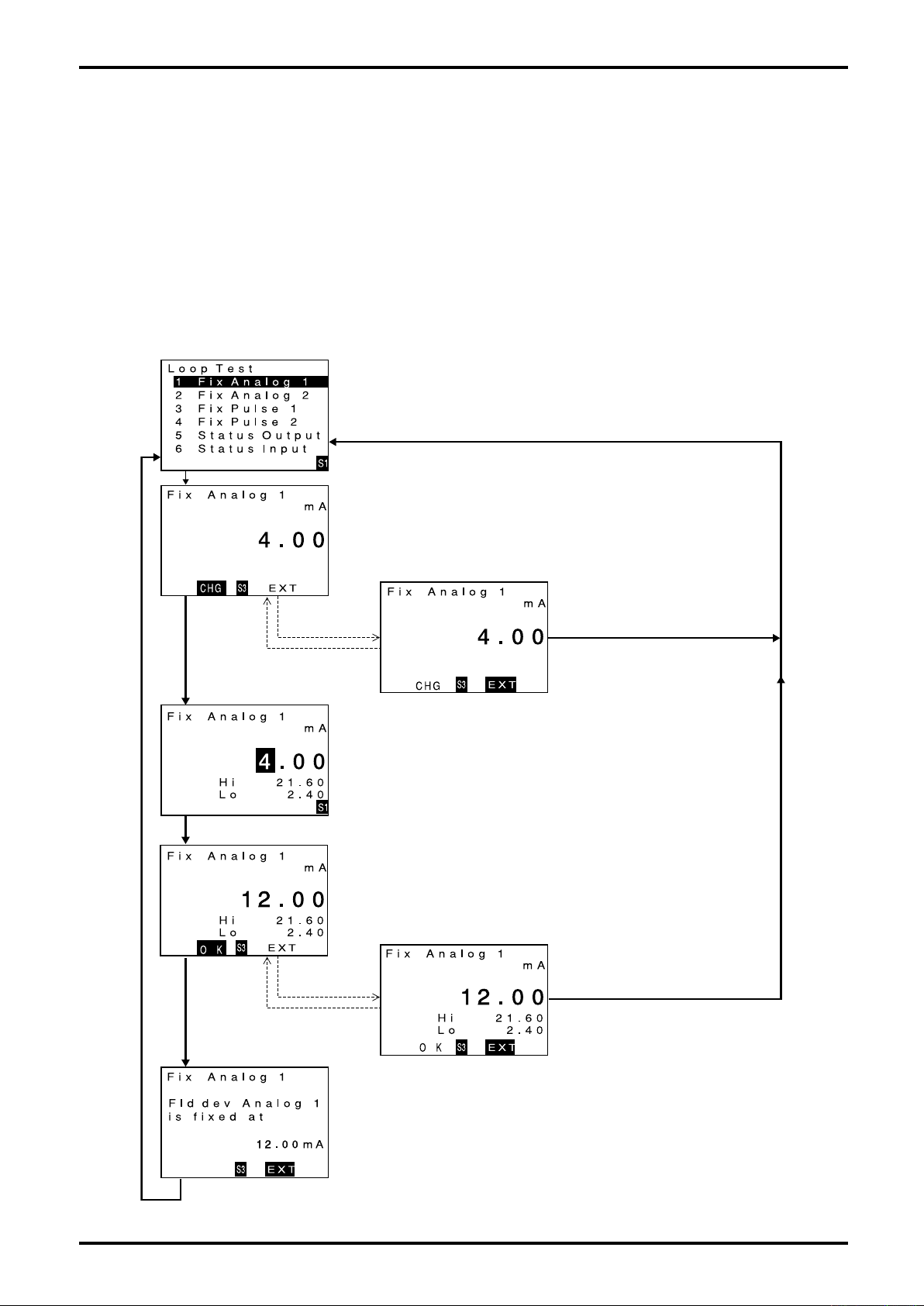
L-737-3-E
9.7 Simulated Signal Input/Output Capabilities
This transmitter features simulated output and input monitor functions. They are beneficial for running a
loop check after installation and for diagnosing erratic flow signals.
9.7.1 Analog output
An analog output is available at any current magnitude.
(The procedure to provide a 12.00mA simulated output of analog output 1 is described here in the
example below.)
(For key-in procedure, see 9.1.1 Key operation.)
(1) Bring up the item of function you want to use.
Firstly, proceed key operation to show a screen for simulated output of analog
output 1. (For the procedure to view individual items, see 9.2.2 thru 9.2.7
Transition chart.) When the cursor is placed over simulated output of analog
output 1 (Fix Analog 1), click "SEL1" to bring up the simulated output setup
screen for analog output 1.
Click "SEL1".
Click "SEL3".
Click "ENT".
Click "ENT".
(2) Decide whether to activate the function or not.
If you want to start simulated output of pulse output 1, click "SEL3" to proceed
to the next screen.
To abort the process without producing a simulated output, click "ENT" and
then click "SEL3". The window returns to menu select screen.
Click "SEL3".
(3) Enter a simulated output value.
Set up a simulated current output current value desired.
For setup procedure, see 9.3 Parameter Value Setup (3).
(In the following screen, a value 12.0000 is finalized.)
(4) Run a simulated output
① If a simulated output "12.0000" displayed is definitely OK, click "SEL3".
If you want to abort the simulated output process, click "ENT" and then click
"SEL3". The window returns to menu select screen
56
Click "SEL3".
Click "SEL3".
Click "ENT".
Click "ENT".
(5) Simulated output of analog output 1 is now generated.
Output of analog output 1 is fixed to 12.00mA.
(Unaffected by obtained measurements, error processing or other factors.)
(During the check, GFN LED blinks on and off.)
If you want to cancel the simulate output process, click "SEL3".
Simulated output stops and the window returns to initial menu select screen.
Page 57
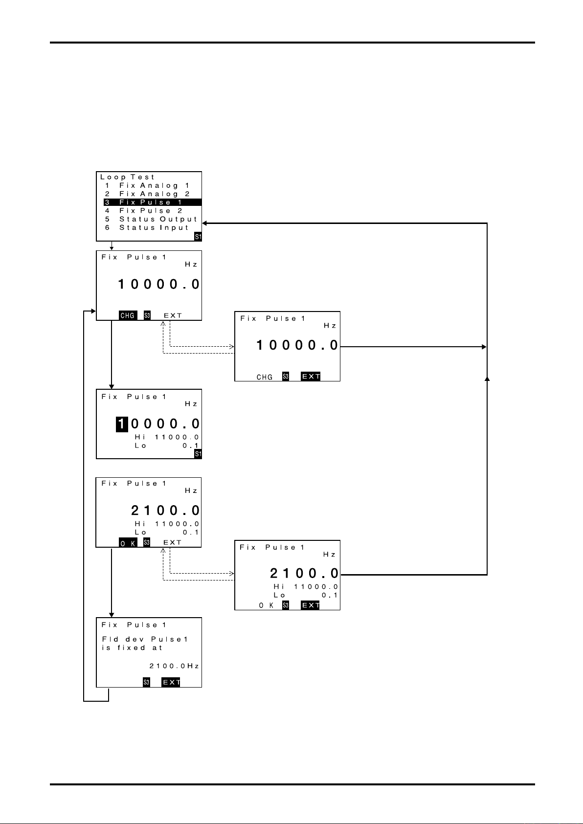
L-737-3-E
9.7.2 Pulse output
A pulse output is available at any frequency desired.
(Simulated output in pulse output 1 is described here in the example below.)
This section covers the procedure to provide a 2100Hz simulated pulse output. A similar procedure applies
to other output settings.
(1) Bring up the item of function you want to use.
Firstly, proceed key operation to show a screen for simulated output of pulse
output 1 (Fix Pulse 1).
(For the procedure to view individual items, see 9.2.2 thru 9.2.7 Transition chart.)
When the cursor is placed over simulated output of pulse output 1 (Fix Pulse 1),
click "SEL1" to bring up simulated output setup screen for pulse output 1.
Click "SEL1".
Click "SEL3".
Click "ENT".
Click "ENT".
(2) Decide whether to activate the function or not.
If you want to start simulated output of pulse output 1, click "SEL3" to proceed
to the next screen.
To abort the process without running a simulated output, click "ENT" and then
"SEL3". The window returns to menu select screen.
Click "SEL3".
(3) Enter a simulated output value.
Set up a simulated output frequency desired.
For the setup procedure, see 9.3 Parameter Value Setup (3).
(In the following screen, a value 2100.00 is finalized.)
(4) Run a simulated output.
If a simulated output "2100.0" is definitely OK, click "SEL3".
If you want to abort the simulated output process, click "ENT" and then click
"SEL3".
The window returns to menu select screen.
Click "SEL3".
Click "SEL3".
Click "ENT".
Click "ENT".
Click "SEL3".
(5) Simulated output of pulse output 1 is now generated.
Output of pulse output 1 is fixed to 2100Hz.
(Unaffected by obtained measurements, error processing or other factors.)
(During the check, GRN LED blinks on and off.)
If you want to cancel the simulate output process, click "SEL3".
Simulated output stops and the window returns to initial menu select screen.
57
Page 58
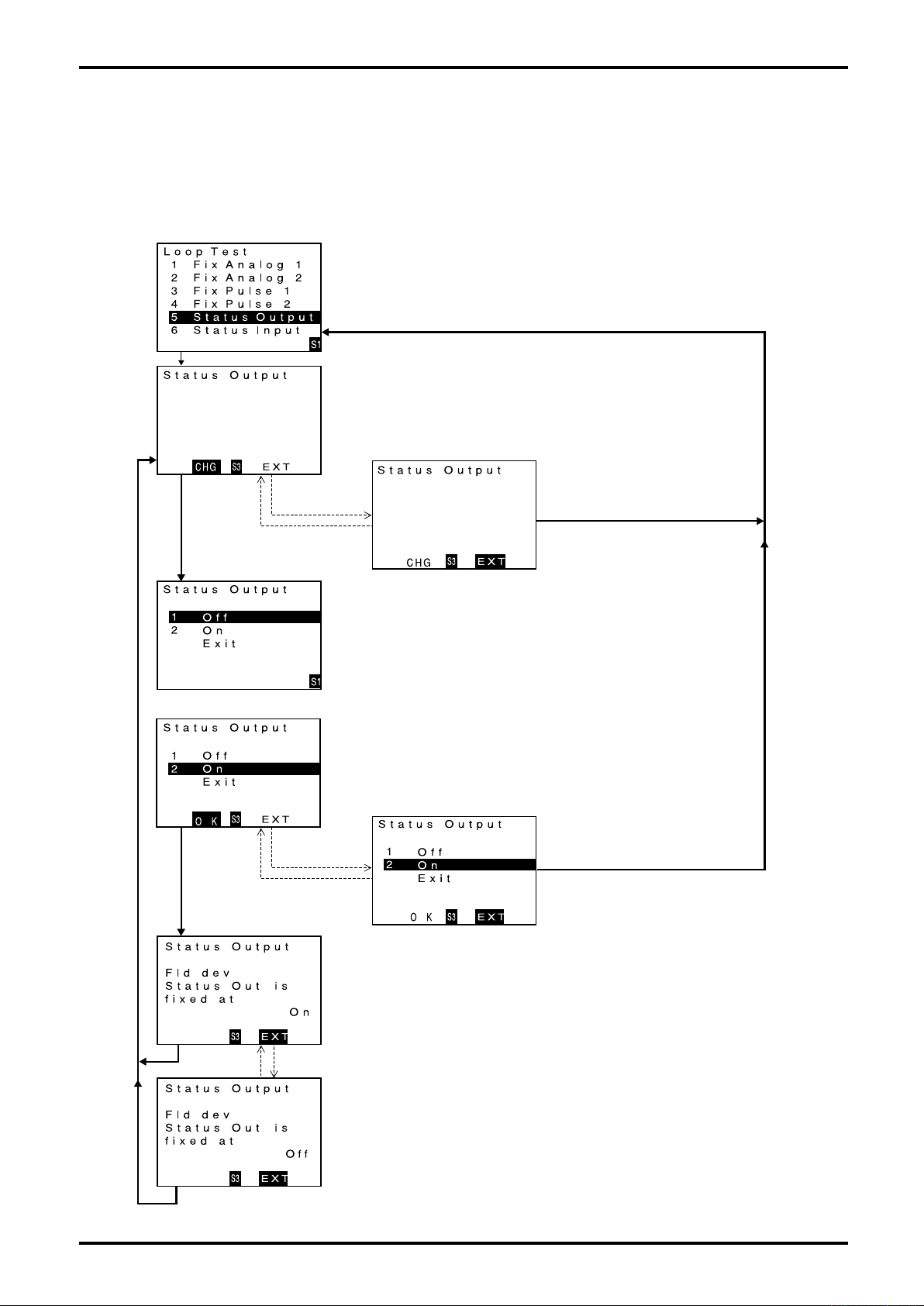
L-737-3-E
9.7.3 Status output
A status output is available at any level desired.
This section covers the procedure to provide a simulated status output in the setting ON. A similar
procedure applies to other output settings
(1) Bring up the item of function you want to use.
Firstly, proceed key operation to show a screen for simulated output of status
output (Status Output).
(For the procedure to view individual items, see 9.2.2 thru 9.2.7 Transition
chart.)
When the cursor is placed over Status Output, click "SEL1" to bring up
simulated output setup screen for status output.
Click "SEL1".
Click "SEL3".
Click "ENT".
Click "ENT".
(2) Decide whether to activate the function or not.
If you want to start simulated output of status output, click "SEL3" to proceed
to the next screen.
To abort the procedure without running a simulated output, click "ENT" and
then "SEL3". The window returns to menu select screen.
Click "SEL3".
(3) Enter a simulated output value.
Select the simulated output mode.
For the setup procedure, see 9.4 Parameter Selection (3).
(4) Run a simulated output.
If setting "On" is definitely OK, click "SEL3".
If you want to abort the simulated output process, click "ENT" and then click
"SEL3".
The window returns to menu select screen.
58
Click "SEL3".
Click "SEL3".
Click "SEL3".
Click "ENT".
Click "ENT".
Click "ENT".Click "ENT".
Click "SEL3".
(5) Status output is now generated.
Output of status output is fixed to On.
(Unaffected by obtained measurements, error processing or other factors.)
(During the check, GRN LED blinks on and off.)
If you want to cancel the simulate output process, click "SEL3".
Simulated output stops and the window returns to initial menu select screen.
Page 59
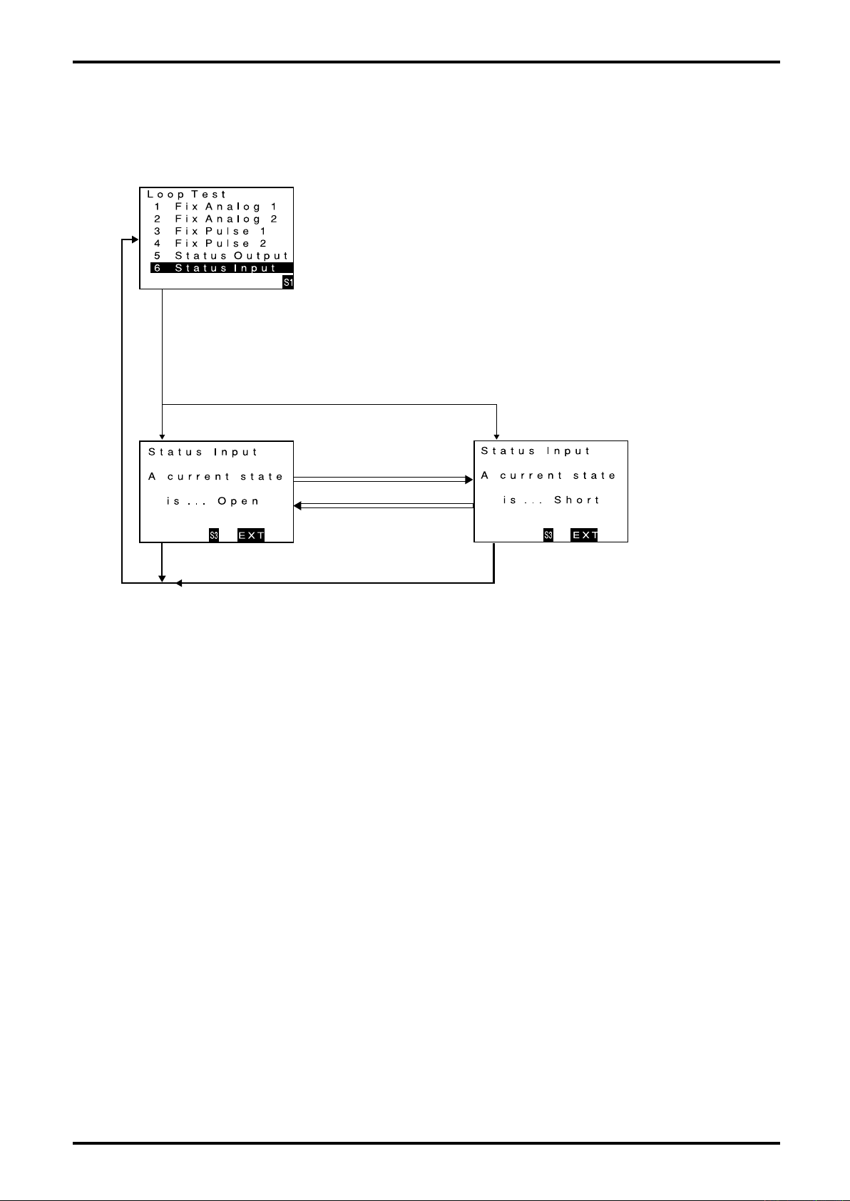
9.7.4 Status input
You can monitor the status of status input signal.
(1) Bring up the item of function you want to use "ENT".
Firstly, proceed key operation to show a screen for Status Input monitor.
When the cursor is placed over status input monitor (Status Input), click "SEL1"
to bring up status input monitor screen.
Click "SEL1".
(2) Status input monitor active now.
The screen changes in the status input monitor mode.
If you want to cancel the input monitor mode, click "SEL3".
Input monitor mode is canceled and the window returns to menu select screen.
L-737-3-E
★
Status signal is in the open.
★
Status signal is in the short.
★
Status signal is in the open.
Click "SEL3". Click "SEL3".
★
Status signal is in the short.
59
Page 60
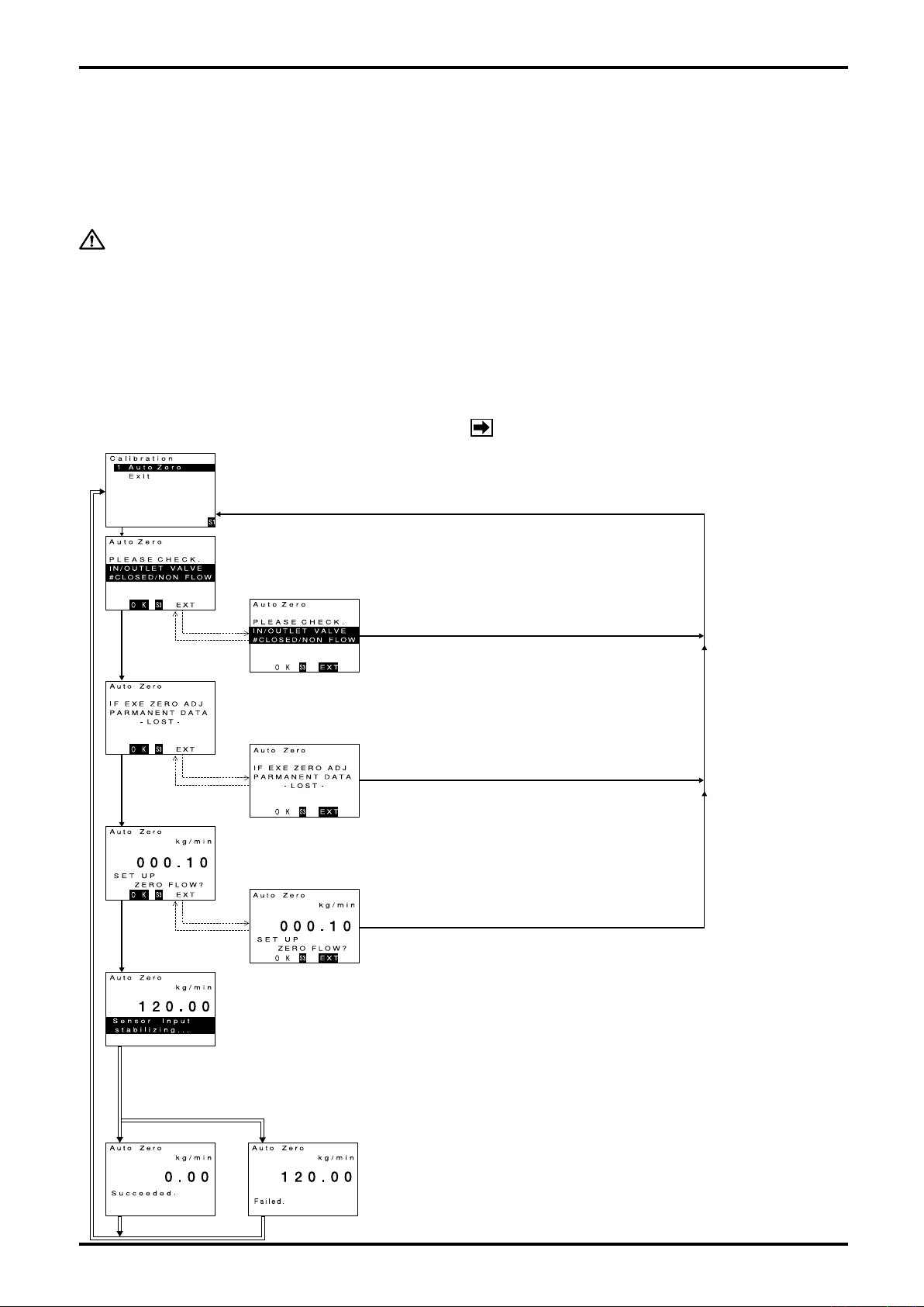
L-737-3-E
9.8 Zeroing Function
This feature detects errors in zeroing and reduces offset flowrate drift to minimum. At the stage of
installation and in cases where flow conditions significantly change, zeroing is an essential part of the
routines required for maintaining accurate and consistent measurement.
During the zeroing, fill the sensor unit completely with the fluid the temperature of which is within ±10℃
from the temperature at which it operates.
CAUTION: 1. Before using this function, close both the display lid and the terminal lid of
the transmitter and make sure that the transmitter is in the condition as the
actual operating condition.
2. Fluid (liquid or gas) must completely fill the flow tube and be absolutely at
zero flow.
3. Accurate zeroing cannot be achieved unless fluid flow is completely halted.
4. Ensure that the shutoff valve has no leaks.
Zero adjustment comes in three options: with LCD switches, with status input, and through
communication. Each has identical functions. Choose one that best suits your task.
9.8.1 Through LCD display switches
(1) Bring up the item of function you want to use.
Firstly, proceed key operation to show Calibration (Auto Zero) screen.
(For the procedure to view individual items, see 9.2.2 thru 9.2.7 Transition chart.)
When the cursor is placed over zeroing (Auto Zero), click "SEL1" to bring up the next
confirmation screen.
Click "SEL1".
Click "SEL3".
Click "ENT".
Click "SEL3".
Click "ENT".
(2) Confirm zero flow
Shut off valves before after the meter and verify that fluid flow is halted.
Upon confirmation of steady state, click "SEL3" to proceed to the next screen.
If fluid flow is not completely halted, click "ENT" followed by clicking "SEL3".
Do not attempt zeroing. (Ensure zero flow once again before you perform zeroing.)
Click "ENT".
(3) Confirm precautionary notes during zeroing.
Performing zeroing overwrites previous zero setting.
Reconfirm. If no problem is found, click "SEL3" to proceed to the next screen.
If you want to reconfirm the state, click "ENT" followed by clicking "SEL3". Do not
attempt to run zeroing. (Upon reconfirmation of the state, perform zeroing.)
Click "ENT".
(4) Confirm before performing the zeroing
The current zero offset is shown.
If you want to perform zeroing, click "SEL3" to proceed to the next screen.
If you want to reconfirm the state, click "ENT" followed by clicking "SEL3". Do not run
zeroing. (Upon reconfirmation of the state, you may perform zeroing.)
Click "SEL3".
Click "SEL3".
NOTE:
This function is disabled in Write Protect
mode (refer to section 9.2).
60
★
Zeroing successful
★
3 sec elapsed
Click "SEL3".
(5) Zeroing in progress
Zeroing is now in progress. (During the zero adjustment, GRN LED blinks on and off.)
As a warning, RED backlight lights for 1 sec at start and end of zeroing.
(Zeroing lasts for 30 sec. approx.)
(6) Auto zero results
Upon completion of auto zero, results are indicated; 3 sec later, the window returns to menu select screen.
If zeroing has failed, you cannot expect accurate measurement in this state.
Reconfirm the state and perform the zeroing once again.
In case of auto zero failure, an error message "Auto Zero Failure" appears.
(For details, see 10.1 Error Messages.)
★
Zeroing failed
★
3 sec elapsed
Page 61

L-737-3-E
9.8.2 Through status input signal
You can perform the zeroing with status input signal. Follow the procedure given below for preparation
and operation:
(1) Preparation to assign status input to zeroing
・Set status input function to "Auto Zero".
(For details of setup, see 9.15 Status Input and 9.2.5 Transition chart (4) [No. 2-5-1].
・Set input mode of status input.
(For details of setup, see 9.15 Status Input and 9.2.5 Transition chart (4) [No. 2-5-2].
(2) Preparation to assign zeroing in progress to status output
(You can perform the zeroing without this setting. You may omit this procedure if not required.)
By completing the settings that follow, you can monitor the zeroing status with status output.
・Set function assignment of status output to "Error Status".
・Set adjustment item of status output to "On".
・Set working output of status output. (For detail of setup procedure, see 9.14.3 Status output and
9.2.5 Transition chart (4) [No. 2-4-5-1], [No. 2-4-5-2-8], and [No. 2-4-5-3].
(3) Procedure to run the zeroing
By working with separately input, you can perform the zeroing. Follow the procedure outline below:
① Preparation
Verify the following precautions:
During the zeroing, fill the sensor unit completely with the fluid the temperature of which is
within ±10℃ from the temperature at which it operates.
CAUTION: 1. Fluid (liquid or gas) must completely fill the flow tube and be absolutely at
zero flow.
2. Accurate zeroing cannot be achieved unless fluid flow is completely halted.
3. Ensure that the shutoff valves, etc. have no leaks.
② Run the zeroing: set the status input to 0.3 sec or longer in the "Short" (when input mode is
"Short"). Upon detection of an input, the zeroing process starts and this process lasts in about
30 seconds.
In the event zeroing has failed, you cannot expect accurate measurement. Upon completion of
zeroing, do not forget to run a check for possible errors.
9.8.3 Through Link Top communication
Zeroing can be conducted through communication, using the software Link Top. For detail of procedure,
see the Link Top instruction manual.
NOTE:
This function is disabled in Write Protect
mode (refer to section 9.2).
61
Page 62
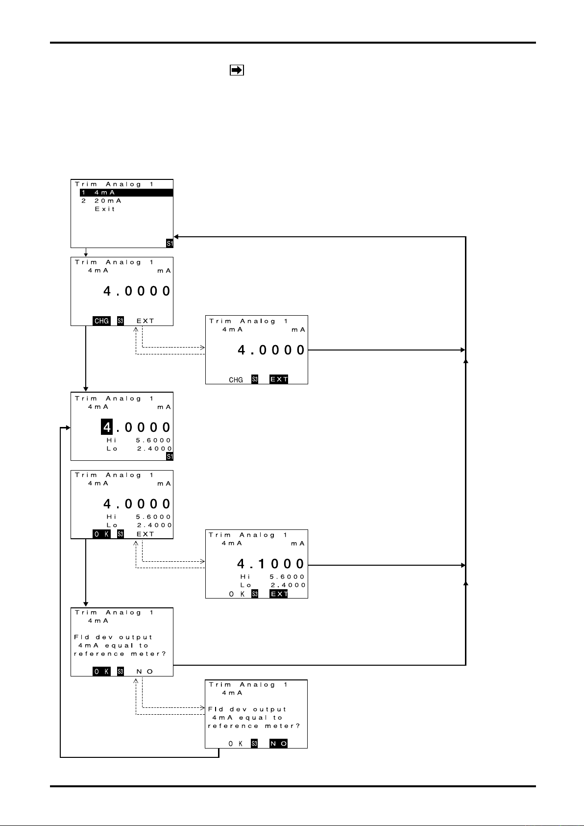
L-737-3-E
9.9 Analog Trim Function
NOTE:
This function is disabled in Write Protect mode
(refer to section 9.2).
The transmitter is provided with two analog outputs. Both are factory adjusted and requires no further
adjustment. However, if it is absolutely necessary to readjust, follow the instructions outlined below.
Prior to making adjustment, connect required measuring instruments in place for making output level
measurement of analog output. Covered below is the procedure to make 4mA trim of analog output 1
(trimming 4.1mA to 4mA in the example below). A similar procedure applies to other adjustments.
(1) Bring up the item of function you want to use.
Firstly, proceed key operation to show Trim Analog 1 screen (4mA trim of analog output 1).
(For the procedure to view individual items, see 9.2.2 thru 9.2.7 Transition chart.)
When the cursor is placed over 4mA trim of analog output 1, click "SEL1" to bring up
4mA trim screen of analog output 1.
Click "SEL1".
Click "SEL3".
Click "ENT".
Click "ENT".
(2) Decide whether to perform analog trim or not.
To perform 4mA trim of analog output 1, click "SEL3" to proceed to the next
screen.
If you want to cancel the trim process, click "ENT" followed by clicking "SEL3" and
the window returns to menu select screen.
Click "SEL3".
Click "SEL3".
Click "ENT".
Click "ENT".
(3) Enter the present output value. (The transmitter produces 4mA output now.)
At present, the output of analog output 1 is fixed to 4mA.
Enter the current reading (4.1mA) of the instrument connected.
For the setup procedure, see 9.3 Parameter Value Setup (3).
(In the screen below, a value 4.1000 is finalized.)
(4) Conform the measurement value.
If the measurement value "4.1000" is definitely OK, click "SEL3".
4mA trim of analog output 1 is performed accordingly.
If you want to cancel the trim process, click "ENT" followed by clicking "SEL3" and
the window returns to menu select screen.
Click "SEL3".
(5) Confirm the current reading of analog output1.
Analog output 1 produces the 4mA output that has just been trimmed.
Confirm the current value of the instrument connected.
If the instrument reads 4mA and requires no further trimming, click "SEL3".
But in the case the instrument reads a value different from 4mA, click "ENT"
followed by clicking "SEL3". You are now back to step (3) and ready to try again.
Click "SEL3".
62
Click "ENT".
Click "ENT".
Click "SEL3".
Page 63
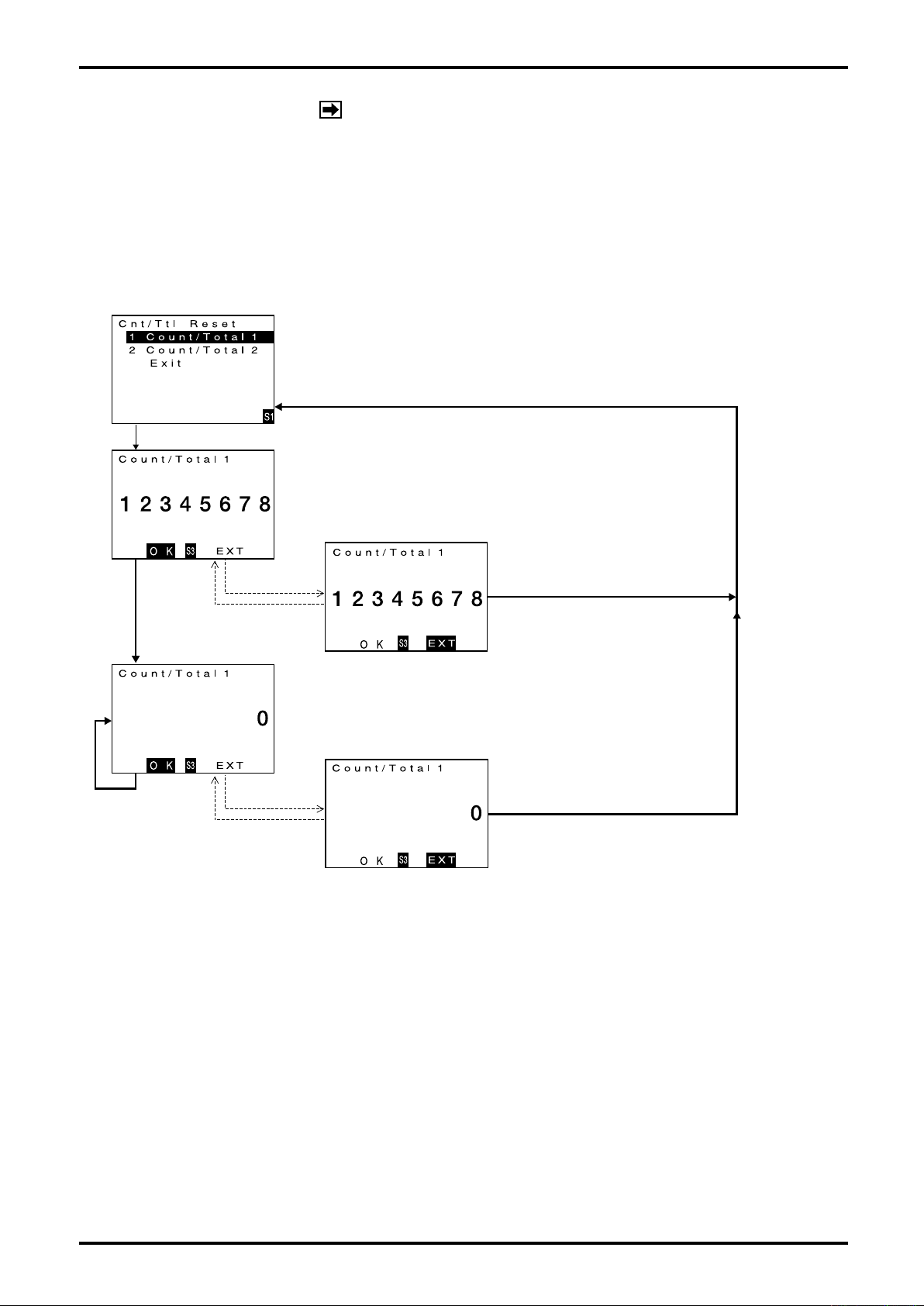
L-737-3-E
9.10 Reset Function
NOTE:
This function is disabled in Write Protect mode
(refer to section 9.2).
The transmitter is provided with two pulse outputs along with two counters (1 and 2) and two totalizers
(1 and 2) which work in sync with pulse output. If it is desired to reset one particular counter and its
associated totalizer, follow the procedure outlined below. (Since the totalizer counts pulses coming in from
the counter, you cannot reset them independently.)
The procedure to reset the counter / totalizer 1 to 0 is described here as an example. The same
procedure applies to the other pair.
(1) Bring up the item of function you want to use.
Firstly, proceed key operation to show counter/totalizer 1 reset (Cnt/Ttl Reset )
screen.
(For the procedure to view individual items, see 9.2.2 thru 9.2.7 Transition chart.)
When the cursor is placed over counter/totalizer 1 reset (Count/Total 1), click "SEL1"
to bring up the Count/Total 1 reset screen.
Click "SEL1".
(2) Decide whether to reset to 0 or not.
The present counter reading is indicated.
If you want to reset to 0, click "SEL3". The next screen appears and the counter
reads 0.
If you want to cancel the reset process, click "ENT" and then click "SEL3".
The window then returns to menu select screen.
Click "SEL3".
Click "SEL3".
Click "ENT".
Click "ENT".
Click "ENT".
Click "ENT".
Click "SEL3".
(3) The present counter reading after the reset operation is indicated.
If you want to abort the reset process, click "ENT" followed by clicking "SEL3"
and the window returns to menu select screen.
If you want to reset to 0 once again, click "SEL3".
Click "SEL3".
63
Page 64
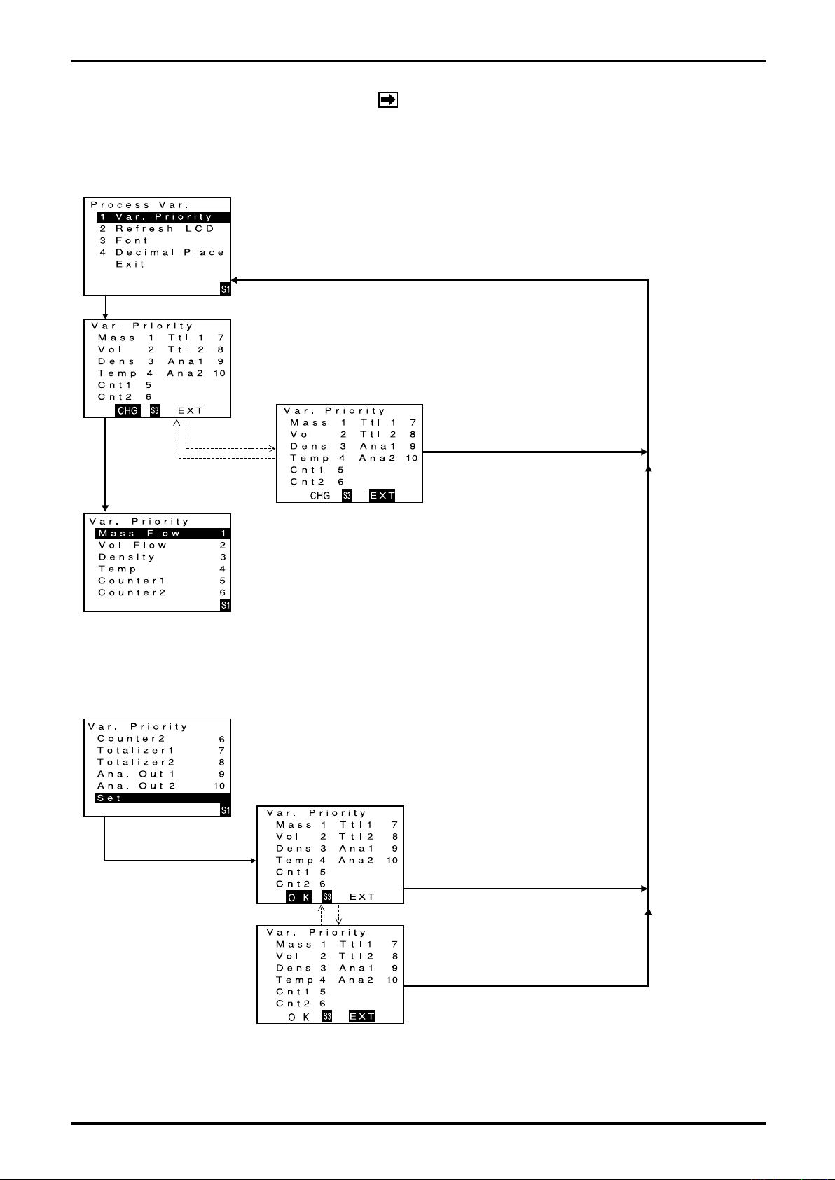
L-737-3-E
9.11 View Variables Screen Setup
NOTE:
For this function, the setting change is disabled
in Write Protect mode (refer to section 9.2).
Display / Hide and priority of variables view can be set up at the view variables screen.
Follow the procedure outlined below:
(1) Bring up the item of function you want to use.
Firstly, proceed key operation to show the variables view priority setup (Var. Priority)
screen.
(For the procedure to view individual items, see 9.2.2 thru 9.2.7 Transition chart.)
When the cursor is placed over variables view priority setup (Var. Priority), click "SEL1"
to bring up Var. Priority setup screen.
Click "SEL1".
(2) Decide whether to change priority of variables or not.
The current priority of variables is shown.
If you want to change the priority, click "SEL3" and the next screen, Var. Priority,
appears.
If you want to cancel the priority change process, click "ENT" followed by clicking
"SEL3" and the window returns to menu select screen.
Click "SEL3".
Click "ENT".
Click "SEL3".
Click "ENT".
Click "SEL1".
(3) View priority setup
The current view variables priority is shown.
Individual items are numbered on the right side according to their view priority. If
0 is set, the affected item disappears from the list. By entering numbers desired
and then scrolling through the list downward, the order of items are rearranged.
(For the setup procedure, see 9.3 Parameter Value Setup (3).)
Available items subject to priority rearrangement are
1. Mass Flow: Instant mass flowrate
2. Vol Fiow: Instant volume rate or instant volume rate (fixed density)
3. Density: Density
4. Temp: Temperature
5. Counter1: Counter reading of pulse output 1
6. Counter2: Counter reading of pulse output 2
7. Tortalizer1: Total flow of pulse output 1
8. Totalizer2: Total flow of pulse output 2
9. Ana Out1: % reading of analog output 1
10. Ana Out2: % reading of analog output 2
Upon completion of setup, move the cursor to "Enter" and click "S1"
A Var. Priority confirmation screen appears.
(4) Finalizing priority
① If the priority is OK, click "SEL3".
Setup is complete and the window returns
to the initial menu select screen.
If you want to abort the setup, click "ENT"
and the screen below appears.
Click "SEL3".
Click "ENT".
Click "ENT".
② If you want to abort setup, click "SEL3".
Setup is complete and the window returns
to the initial menu select screen.
64
Click "SEL3".
Page 65

L-737-3-E
9.12 Pulse Output Function
The transmitter is provided with two pulse outputs which can be set up as independent outputs. Attractive
features include a double pulse output created by allowing two pulses out of phase by 90 or 180 degrees,
and a bidirectional pulse output - linked with status output signal, enabling the operator to discriminate the
direction of flow. Refer to the following topics for description of these features.
(NOTE: When the pulse output assignment, full scale flowrate, or frequency at full scale is modified, the
Counter/Totalizer will be reset.)
NOTE:
For this function, the setting change is disabled in
Write Protect mode (refer to section 9.2).
9.12.1 Pulse output 1
If you want to use pulse output 1, it is required that the following be set up.
For using bidirectional pulse output or double pulse output, be sure to set the assignment of interest.
(1) Setup procedure
① Pulse output 1 assignment (Assign) (See 9.2.4 Transition chart (3) [No. 2-4-3-1].)
Kind of flow is selected.
・Mass Flow: Mass flow
・Volume Flow: Volumetric flow
② Frequency of pulse output 1 at full scale flowrate (Freq Factor) (See 9.2.4 Transition chart (3)
[No. 2-4-3-2].)
The frequency at the flowrate set in ③ is set up. Set it to match the measurable range of the
instrument that measures pulse output. Acceptable setting range is from 0.1 to 10000Hz.
③ Full scale flowrate of pulse output 1 (Rate Factor) (See 9.2.4 Transition chart (3) [No. 2-4-3-3].)
An output is generated at the frequency set in ② when the preset flowrate is reached.
④ Low flow cutoff of pulse output 1 (Lowcut) (See 9.2.4 Transition chart (3) [No. 2-4-3-4].)
When the proportion of flowrate is smaller than the low flow cutoff value - where the flowrate set
in ③ is set to 100% - the output is clamped at 0. Acceptable setting range is from 0.0 to 10.0%.
⑤ The state of pulse output in an error (Pulse) (See 9.2.5 Transition chart (4) [No. 2-4-6-2].)
Pulse output value in an error can be selected from the following three options:
・Zero: Pulse output is halted.
・Hold: Pulse output immediately before an error is maintained.
・Upscale: 11kHz is output. (For detail of output in an error, see 10.1 Error Messages.)
9.12.2 Pulse output 2
If you want to use pulse output 2, it is required that the following be set up.
For using bidirectional pulse output or double pulse output, be sure to set the assignment of interest.
(In the case of double pulse output, set only pulse output 2 assignment. Invalidating parameters other
than that, pulse output 2 is also output with the same setting as that of pulse output 1.)
① Pulse output 2 assignment (Assign) (See 9.2.4 Transition chart(3) [No. 2-4-4-1].) Type of flow to
be assigned is selected.
・Mass Flow: Mass flow
・Volume Flow: Volumetric flow
・Double pulse 90: Double pulse output 90°
・Double pulse -90: Double pulse output - 90°
・Double pulse 180: Double pulse output 180°
As for double pulse output, see 9.12.4 Double pulse output.
As for ②, ③, and ④ below, a procedure similar to pulse output 1 applies. See 9.12.1 Pulse output (1).
② Frequency of pulse output 2 at full scale flowrate (Freq Factor) (See 9.2.4 Transition chart (3)
[No. 2-4-4-2].)
③ Full scale flowrate of pulse output 2 (Rate Factor) (See 9.2.4 Transition chart (3) [No. 2-4-4-3].)
④ Low flow cutoff of pulse output 2 (Lowcut) (See 9.2.4 Transition chart (3) [No. 2-4-4-4].)
⑤ The state of pulse output in an error (Pulse) (See 9.2.5 Transition chart (4) [No. 2-4-6-2].)
65
Page 66
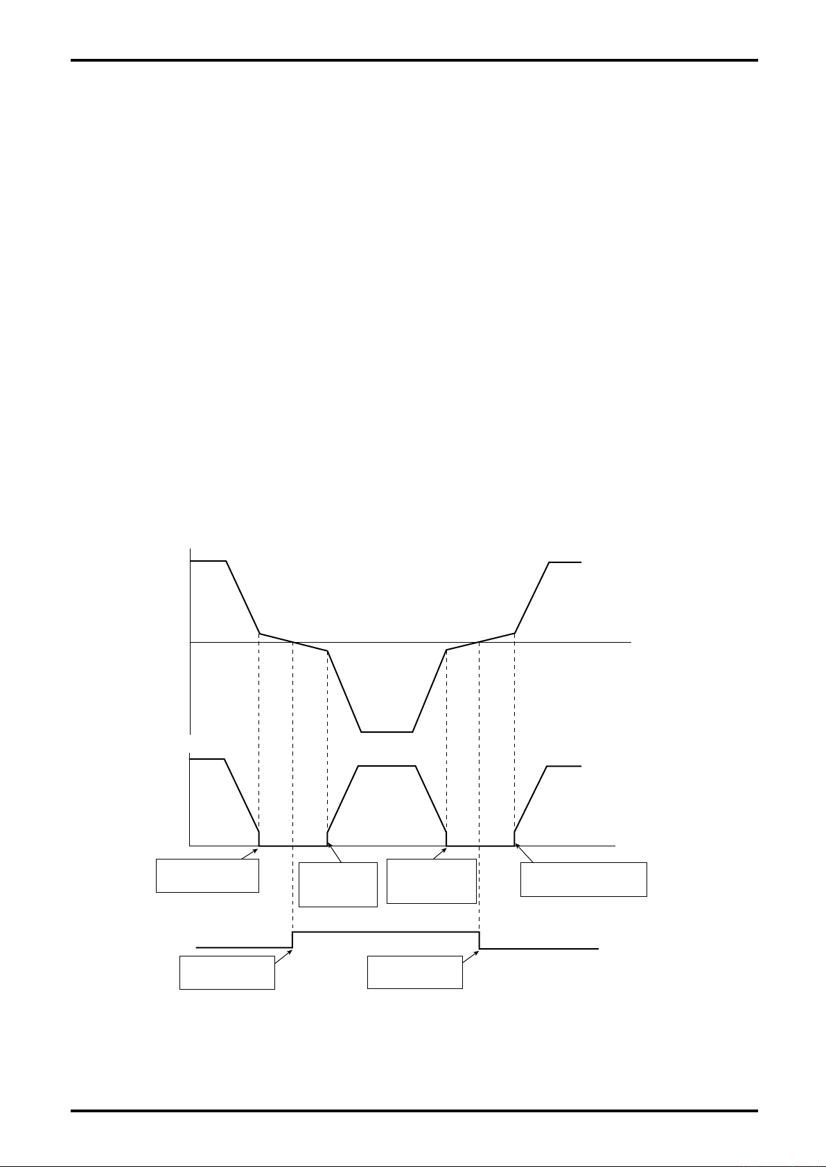
L-737-3-E
100
80
60
40
20
0
-20
-40
-60
-80
-100
1000
800
600
400
200
0
Open
Short
Lowflowcutofffreq.
100[Hz]
=1000「Hz]10[%]/100"
Time
Output clamped at 0
due to proportion of
flowrate<lowcutoff.
StatusoutputisOpen
as flowrate goes
negative
below0.
StatusoutputisShort
asflowrategoes
positive
below0.
Output appears due to
proportion of flowrate >
lowcutoff.
Output appears
dueto proportion
offlowrate> low
cutoff.
Output clamped at
0duetoproportion
of flowrate < low
cutoff.
Massflowrate[kg/min]
Outputfreq.[Hz]
Statusoutput
9.12.3 Bidirectional pulse output
By allowing status output signal to provide flow direction information, the transmitter distinguishes
between pulse outputs in the forward and reverse flow, and counts up pulses independently. (Hence, it
requires on the part of measuring instrument a circuit to distinguish the directions of flow.) To utilize this
function, you need to set up the following in addition to settings of pulse outputs 1 and 2.
(1) Setup procedure
① Status output function assignment (Function) (See 9.2.5 Transition chart (4) [No. 2-4-5-1].)
・Select Bi Direction.
② Active output of status output (Mode) (See 9.2.5 Transition chart (4) [No. 2-4-5-3].)
Set the active output status of status output.
・Off Active: Output is in the Short in the forward fluid flow.
・On Active: Output is in the Open in the forward fluid flow.
(2) An example of settings and assignments
Status output function assignment (Function): Bi Direction
Active output of status output (Mode): Off Active
Pulse output 1 assignment (Assign): Mass Flow
Frequency of pulse output 1 at full scale flowrate (Freq Factor): 1000 [Hz]
Full scale flowrate of pulse output 1 (Rate Factor): 100.0 [kg/min]
Low flow cutoff of pulse output 1 (Lowcut): 10.0 [%]
66
Page 67
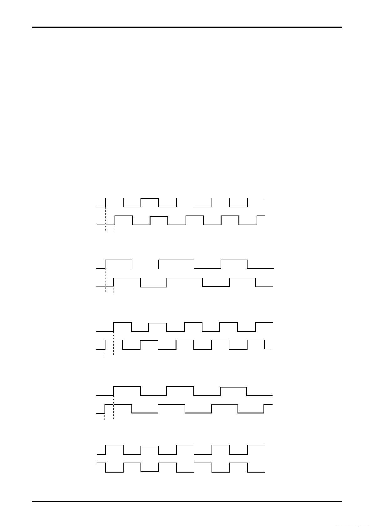
Pulseout1
Pulseout2
Pulseout1
Pulseout2
Pulseout1
Pulseout2
Pulseout1
Pulseout2
Pulseout1
Pulseout2
90
(1/4oftheperiod)
1msec
90
(1/4oftheperiod)
1msec
9.12.4 Double pulse output
This function provides pulse output 2 in sync with pulse output 1.
It is enabled by setting up one of the following to pulse output 2 assignment.
(1) Setup procedure
① Pulse output 2 assignment (Assign)
・Double pulse 90: Double pulse output 90°
Pulse output 2 lags pulse output 1 by 90 degrees (1/4 of the period) when it goes into action.
(The maximum lag is 1 msec, above which is a lag within 1/4 of the period, however.)
・Double pulse -90: Double pulse output -90°
Pulse output 1 lags pulse output 2 by 90 degrees (1/4 of the period) when it goes into action.
(The maximum lag is 1 msec, above which is a lag within 1/4 of the period, however.)
・Double pulse 180: Double pulse output 180°
Pulse output 2 goes into action, polarity of pulse output 1 waveform inverted.
(2) Examples of setting and behavior
① Double pulse 90°
・Fast pulse output (above 250Hz)
L-737-3-E
・Slow pulse output (below 250Hz)
② Double pulse -90°
・Fast pulse output (above 250Hz)
・Slow pulse output (below 250Hz)
③ Double pulse 180°
67
Page 68

L-737-3-E
9.13 Analog Output Function
The transmitter is provided with two analog outputs which can be assigned to "mass flow", "volume flow",
"temperature", "density" and "drive output". The setup procedure is outlined below:
NOTE:
For this function, the setting change is disabled in
Write Protect mode (refer to section 9.2).
(1) Setup procedure
By reconfiguring the following five parameters, outputs that suit your particular application are made
available.
① Output assignment (Assign) (See 9.2.4 Transition chart (3) [No. 2-4-1-1] and [No. 2-4-2-1].)
Types of measurement are selected.
・Mass Flow: Instant mass flowrate
・Vol Flow: Instant volume flowrate
・Density: Density
・Temp: Temperature
・Drive Output: Drive output
When assignments are modified, reconfigure upper limit, lower limit, low flow cutoff, and damping
factor to values that best suit your application.
② Upper limit value (URV) (See 9.2.4 Transition chart (3) [No. 2-4-1-2] and [No. 2-4-2-2].)
The lower limit of analog output can be changed; a 4mA output is produced when the preset
value is reached. Values outside the maximum range (※1) and smaller than the lower limit value
are unacceptable, however.
③ Lower limit value (LRV) (See 9.2.4 Transition chart (3) [No. 2-4-1-3] and [No. 2-4-2-3].)
The upper limit of analog output can be changed; a 20mA output is produced when the preset
value is reached. Values outside the maximum range (※1) and larger than the upper limit value
are unacceptable, however.
④ Low flow cutoff (Lowcut) (See 9.2.4 Transition chart (3) [No. 2-4-1-4] and [No. 2-4-2-4].)
The low flow cutoff of analog output (%) can be changed. When the low flow cutoff value is
larger than the proportion of analog output - where the upper limit is set to 100% and the lower
limit is 0% - the analog output becomes 4mA. Acceptable setting range is from 0% to 10%.
⑤ Damping factor (Added Damp) (See 9.2.4 Transition chart (3) [No. 2-4-1-5] and [No. 2-4-2-5].)
Damping constant of analog output (sec) can be changed. Select a larger value when analog
output fluctuates excessively; select a smaller value when fast response is desired.
Acceptable setting range is from 0 to 200 (sec).
⑥ The state of analog output in an error (Analog) (See 9.2.5 Transition chart (5) [No. 2-4-6-1].)
・Downscale: 2.4mA is output.
・Zero: 4mA is output.
・Hold: Analog output immediately before an error is maintained.
・Upscale: 21.6mA is output.
(For details of outputs in an error, see 10.1 Error Messages.)
※1 Maximum range
Instant mass flowrate: - Max. allowable range to max. allowable range
Instant volume flowrate: - Max. allowable range/0.3 to max. allowable range/0.3
Temperature: Max. temperature range of sensor
Density: 0.0 to 5.0
CAUTION: When measurement-related unit set up at Assign is modified, the
upper and lower limit values will be converted automatically to the
measures to read in the unit selected.
68
Page 69

L-737-3-E
9.14 Status Output
One output chosen from status information, flow direction, and alarm state can be assigned to the status
output.
For details of individual functions, refer to the respective items below:
NOTE:
For this function, the setting change is disabled in Write Protect
mode (refer to section 9.2).
9.14.1 Status output (Error Status)
By assigning the output of status information to the status output, the state of the flowmeter of interest can
be output. Listed below are user assignable flowmeter-related items that can be set up and configured
individually.
・Sensor error (Sensor Failure)
・Transmitter warning (Txr Failure)
・Calibration error (Calibration Failure)
・Output error (Saturated Alarm)
・Parameter alarm (Parameter Alarm)
・Transmitter alarm (Transmitter Alarm)
・Slug flow alarm (Slug Alarm)
・Calibration in progress (Cal in Progress)
・Simulated output being produced (Fix Output)
(For details, see 10.1 Error Messages and 10.2 Status Messages.)
(1) Operating procedure
・Select "Error Status" in selecting the status output function assignment. (See 9.2.5 Transition
chart (4) [No. 2-4-5-1].)
・The flowmeter-related states listed above are available for an output; set up each item to either on
or off. (See 9.2.5 Transition chart (4) [No. 2-4-5-2-1] thru [No. 2-4-5-2-9].)
・Set up the active output of status output. According to the settings, the following outputs become
available.
With setting "On Active", the output is Short when the preset state is reached.
With setting "Off Active", the output is Open when the preset state is reached.
(See 9.2.5 Transition chart (4) [No. 2-4-5-4].)
When the settings above take effect, the functions are ready for use.
9.14.2 Bidirectional flow direction output (Bi Direction)
By selecting the bidirectional output for status output, an output representing the flow direction becomes
available.
Pulse output is normally available in the forward direction, but with the bidirectional output setup, pulse
output in the reverse direction is also available. (For details, see 9.12.3 Bidirectional pulse output.)
(1) Operating procedure
・Select "Bi Direction" in selecting the status output function assignment. (See 9.2.5 Transition chart
(4) [No. 2-4-5-1].)
・Set the active output of status output. According to the settings, the following outputs become
available.
With setting "On Active", the output is Short when the fluid flows in the reverse direction.
With setting "Off Active", the output is Open when the fluid flows in the reverse direction.
(See 9.2.5 Transition chart (4) [No. 2-4-5-4].)
When the settings above take effect, the functions are ready for use.
69
Page 70

L-737-3-E
9.14.3 H/L alarm output (H/L Alarm)
By assigning the high/low alarm output to the status output, an error output of high/low alarm of interest
can be provided. Listed below are available variables that can be set up.
・Mass Flow: Instant mass flowrate
・Vol Flow: Instant volume flowrate
・Dens: Density
・Temp: Temperature
・Counter 1: Counter 1
・Counter 2: Counter 2
(For details of high/low alarms, see 9.16 High/Low Alarm Functions.)
(1) Operating procedure
・Select "H/L Alarm" in selecting the status output function assignment; the state of high/low alarm
can then be output. (See 9.2.5 Transition chart (4) [No. 2-4-5-1].)
・Set the output of status output. According to the settings, the following outputs become available.
With setting "On Active", the output is in the Short in an alarmed condition of high/low alarms.
With setting "Off Active", the output is in the Open in an alarmed condition of high/low alarms.
(See 9.2.5 Transition chart (4) [No. 2-4-5-4].)
When the settings above take effect, the functions are ready for use.
9.14.4 Drive Output Alarm (Used for maintenance purpose)
By assigning the drive output alarm to status output, the alarm can be activated when the drive output
exceeds the threshold.
(1) Operating procedure
・Select "Drive O Alm." for the status output function assignment; the state of drive output can then
be output.
(See 9.2.5 Transition chart (4) [No. 2-4-5-1])
・Enter the threshold to determine at what percentage of the drive output the alarm output should
be activated. The initial value is 100%.
(See 9.2.5 Transition chart (4) [No. 2-4-5-3])
・Set the output of status output. When this setting takes effect, the following status output appears.
With setting "On Active", the output is always in the Short.
With setting "Off Active", the output is always in the Open.
(See 9.2.5 Transition chart (4) [No. 2-4-5-4])
The function becomes available by setting the above.
9.14.5 No assignment (No Function)
When this setting takes effect, the following status output appears.
With setting "On Active", the output is always in the Short.
With setting "Off Active", the output is always in the Open.
(1) Operating procedure
・Select "No Function" in selecting the status output function assignment. (See 9.2.5 Transition
chart (4) [No. 2-4-5-1].)
70
Page 71

L-737-3-E
9.15 Status Input Function
One of "pulse/analog output fixed to 0%", "zeroing", "totalizer 1 and totalizer 2 reset", "totalizer 1 reset", or
"totalizer 2 reset" can be assigned to the status input.
For details of individual functions, refer to the respective items below.
NOTE:
For this function, the setting change is disabled in Write
Protect mode (refer to section 9.2).
9.15.1 Pulse/analog output fixed to 0% (0% Sig Lock)
When an input arrives across status input terminals, pulse output and analog output are fixed to 0Hz and
0mA, respectively.
Stopping an input across status input terminals cancels fixing of the output.
(1) Operating procedure
・Select "0% Sig Lock" in selecting the status input function assignment.
(See 9.2.5 Transition chart (4) [No. 2 to 5-1].)
・Set the input mode of status input. According to the settings, the following input mode will be
enabled:
"Short Active" setting: the function is activated 0.3 seconds after the condition of the circuit
between status input terminals is changed from opened to shorted.
"Open Active" setting: the function is activated 0.3 seconds after the condition of the circuit
between status input terminals is changed from shorted to opened.
(See 9.2.5 Transition chart (4) [No.2-5-2])
The function becomes available by setting the above.
9.15.2 Zero adjustment (Auto Zero)
When an input arrives across status input terminals, automatic zero is initiated to reduce offset flowrate
drift to minimum.
(For detail of the function, see "9.8 Zeroing Function".)
(1) Operating procedure
・Select "Auto Zero" in selecting the status input function assignment.
(See 9.2.5 Transition chart (4) [No. 2-5-1].)
・Set the input mode of status input. According to the settings, the following input mode will be
enabled:
"Short Active" setting: the function is activated 0.3 seconds after the condition of the circuit
between status input terminals is changed from opened to shorted.
"Open Active" setting: the function is activated 0.3 seconds after the condition of the circuit
between status input terminals is changed from shorted to opened.
(See 9.2.5 Transition chart (4) [No.2 to 5-2])
The function becomes available by setting the above.
9.15.3 Totalizer 1 and totalizer 2 reset (Reset Total 1 and 2)
The transmitter is provided with counters (Counters 1 and 2) and totalizers (Totalizers 1 and 2) which
work in synchronism with pulse output. When an input arrives across status input terminals, all these
counters - Counters 1 and 2 and Totalizers 1 and 2 - are reset to 0.
In this connection, counter 1 and totalizer 1 respond to pulse 1 output while counter 2 and totalizer 2
respond to pulse 2. (For detail of the function, see 9.10 Reset Function.)
(1) Operating procedure
・Select "Reset C/T 1・2" in selecting the status input function assignment.
(See 9.2.5 Transition chart (4) [No. 2-5-1].)
・Set the input mode of status input. According to the settings, the following input mode will be
enabled:
"Short Active" setting: the function is activated 0.3 seconds after the condition of the circuit
between status input terminals is changed from opened to shorted.
"Open Active" setting: the function is activated 0.3 seconds after the condition of the circuit
between status input terminals is changed from shorted to opened.
(See 9.2.5 Transition chart (4) [No.2 to 5-2])
The function becomes available by setting the above.
71
Page 72

L-737-3-E
9.15.4 Totalizer 1 reset (Reset Total 1)
The transmitter is provided with counters (Counters 1 and 2) and totalizers (Totalizers 1 and 2) which
work in synchronism with pulse output. When an input arrives across status input terminals, counter 1
and totalizer 1 are reset to 0.
In this connection, counter 1 and totalizer 1 respond to pulse 1 output while counter 2 and totalizer 2
respond to pulse 2. (For detail of the function, see 9.10 Reset Functions.)
(1) Operating procedure
・Select "Reset D/T 1" in selecting the status input function assignment.
(See 9.2.5 Transition chart (4) [No. 2 to 5-1].)
・Set the input mode of status input. According to the settings, the following input mode will be
enabled:
"Short Active" setting: the function is activated 0.3 seconds after the condition of the circuit
between status input terminals is changed from opened to shorted.
"Open Active" setting: the function is activated 0.3 seconds after the condition of the circuit
between status input terminals is changed from shorted to opened.
(See 9.2.5 Transition chart (4) [No.2 to 5-2])
The function becomes available by setting the above.
9.15.5 Totalizer 2 reset (Reset Total 2)
The transmitter is provided with counters (Counters 1 and 2) and totalizers (Totalizers 1 and 2) which
work in synchronism with pulse output. When an input arrives across status input terminals, counter 2
and totalizer 2 are reset to 0.
In this connection, counter 1 and totalizer 1 respond to pulse 1 output while counter 2 and totalizer 2
respond to pulse 2. (For detail of the function, see 9.10 Reset Function.)
(1) Operating procedure
・Select "Reset C/T 2" in selecting the status input function assignment.
(See 9.2.5 Transition chart (4) [No. 2 to 5-1].)
・Set the input mode of status input. According to the settings, the following input mode will be
enabled:
"Short Active" setting: the function is activated 0.3 seconds after the condition of the circuit
between status input terminals is changed from opened to shorted.
"Open Active" setting: the function is activated 0.3 seconds after the condition of the circuit
between status input terminals is changed from shorted to opened.
(See 9.2.5 Transition chart (4) [No.2 to 5-2])
The function becomes available by setting the above.
72
Page 73

L-737-3-E
9.16 High/Low Alarm Function
The transmitter provides the operator with quick grasp of conditions of the installation - flowrate,
temperature, density and total flow - when high/low alarms are set up. In the event the preset alarm
conditions are met, it tells the operator the event with an alarm message along with a status output signal.
Setup procedure and behavior of alarm functions are described below:
(1) Setup procedure
Ensure positive settings on individual items.
① Status output function assignment (Function) (See 9.2.5 Transition chart (4) [No. 2-4-5-1].)
To use high/low alarm function, it is essential to assign high/low alarms to status output.
Set "H/L Alarm" to status output function assignment.
("H/L Alarm" setting is required even in cases of high alarm only or low alarm only.)
② Output mode of status output (Mode) (See 9.2.5 Transition chart (4) [No. 2-4-5-3].)
Set up the output mode of status output.
・Active output of status output: Off Active or On Active
(For detail of the status output function, see 9.14 Status Output Function.)
③ Assignment of H/L alarm values (Assign) (See 9.2.5 Transition chart (4) [No. 2-6-1].)
From the following options, select the variables against which the transmitter identifies
alarmed conditions.
・Mass Flow: Instant mass flowrate
・Vol Flow: Instant volume flowrate
・Dens: Density
・Temp: Temperature
・Counter 1: Counter 1
・Counter 2: Counter 2
④ Alarm type selection (H/L Alm. Type) (See 9.2.5 Transition chart (4) [No. 2-6-2].)
Select alarm type from the following options.
・To validate only high alarm, select "High Alarm".
・To validate only low alarm, select "Low Alarm".
・To validate both high and low alarms, select t "H/L Alarm".
⑤ High alarm value setting (High Alm. Po.) (See 9.2.5 Transition chart (4) [No. 2-6-3].)
If the input exceeds this setting, the high alarm is activated. Set the high alarm value
desired.
In the case "Low Alarm" is set in ④, setting is not required.
⑥ Low alarm value setting (Low Alm. Po.) (See 9.2.5 Transition chart (4) [No. 2-6-4].)
・Low Alm. Po.: Low alarm value
In the case "High Alarm" is set in ④, setting is not required.
⑦ Hysteresis value setting for high/low alarms (H/L Alm. hys)
(See 9.2.5 Transition chart (4) [No. 2-6-5].)
The setting determines a dead (or immunity) zone following the occurrence of an alarm.
Select a larger value when measurement fluctuates excessively; select a smaller value if
fast recovery from alarmed condition is desired.
NOTE:
For this function, the setting change is disabled
in Write Protect mode (refer to section 9.2).
73
Page 74
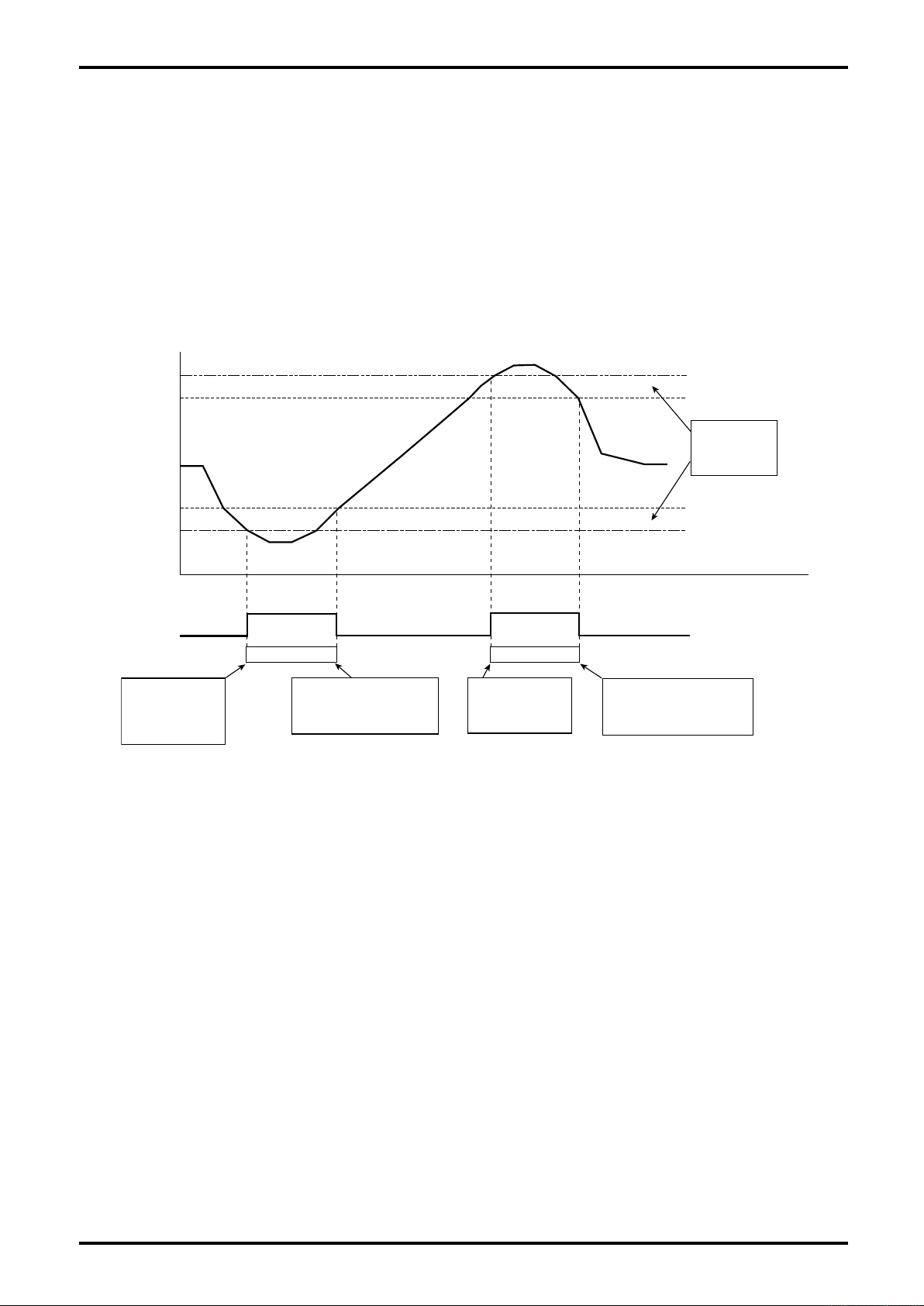
L-737-3-E
}
}
900
800
700
600
500
400
300
200
100
0
Open
Short
High alarm
[900]
Hysteresis
of H/L alarm
[100]
Low alarm
[200]
Time
H/L alm active H/L alm active
Low alarm arises
as instant mass
flowrate falls below
low alarm value.
High alarm arises
as instant mass
flowrate exceeds
low alarm value.
Low alarm canceled as
instant mass flowrate
exceeds [low alarm + H/L
alarm hysteresis].
High alarm canceled as
instant mass flowrate falls
below [high alarm + H/L
alarm hysteresis].
Instant mass flowrate [kg/min]
Status output
(2) An example of settings and assignments
Status output assignment (Function): H/L Alarm
Active output of status output (Mode): Off Active
H/L alarm value assignment (Assign): Mass Flow
Alarm type selection (H/L Alm. Type): H/L Alarm
High alarm value setting (High Alm. Po.): 900 [kg/min]
Low alarm value setting (Low Alm. Po.): 200 [kg/min]
High/low alarm hysteresis value setting (H/L Alm. hys): 100 [kg/mn]
74
Page 75

L-737-3-E
9.17 Gas Mixed Flow Alarm Function
If gases exist in large quantities in the process fluid, it is impossible to make accurate flow measurement.
This feature, if correctly set up, detects gases entrapped in the fluid, indicates a slug flow alarm, clamps
the flow signal at 0, and provides a status output telling the operator the alarm event. (If you want to use
this function, set the higher limit density value of slug flow to 10 (default) and the lower limit density value
of slug flow to 0 (default). This function then remains disabled.) The setup procedure of slug flow function
is outlined below.
(1) Setup procedure
Ensure positive settings of individual items.
① Lower limit density of slug flow (Slug Low) (See 9.2.3 Transition chart (2) [No. 2-2-3].)
Upon detection of density smaller than this setting, the circuitry interprets it as slug flow
and starts analysis.
Set a value small enough with respect to the density expected for the fluid of interest.
② Higher limit density of slug flow (Slug High) (See 9.2.4 Transition chart (2) [No. 2-2-4].)
Upon detection of density larger than this setting, the circuitry interprets it as an error and
starts analysis.
Set a value large enough with respect to the density expected for the fluid of interest.
③ Slug flow identification time (Slug Duration) (See 9.2.5 Transition chart (2) [No. 2-2-5].)
It is the time required for the circuitry to identify the slug flow being outside the slug flow
high/low limit and to issue a slug flow alarm (sec). Until this slug flow identification time
expires, it retains the most recent and properly measured value. After the expiration of this
preset time, the flowrate becomes 0.
④ If you want to assign this slug flow alarm in the status output function to the status output,
setting the following is required: (For detail of this output function, see 9.14 Status Output
Function.)
・Status output function assignment: Error Status (See 9.2.5 Transition chart (2) [No. 2-4-
5-1].)
・Slug flow error select: On (See 9.2.5 Transition chart (4) [No. 2-4-5-2-7].)
・Active output of status output: Off Active or On Active (See 9.2.5 Transition chart (4)
[No. 2-4-5-3].)
NOTE:
For this function, the setting change is disabled
in Write Protect mode (refer to section 9.2).
75
Page 76
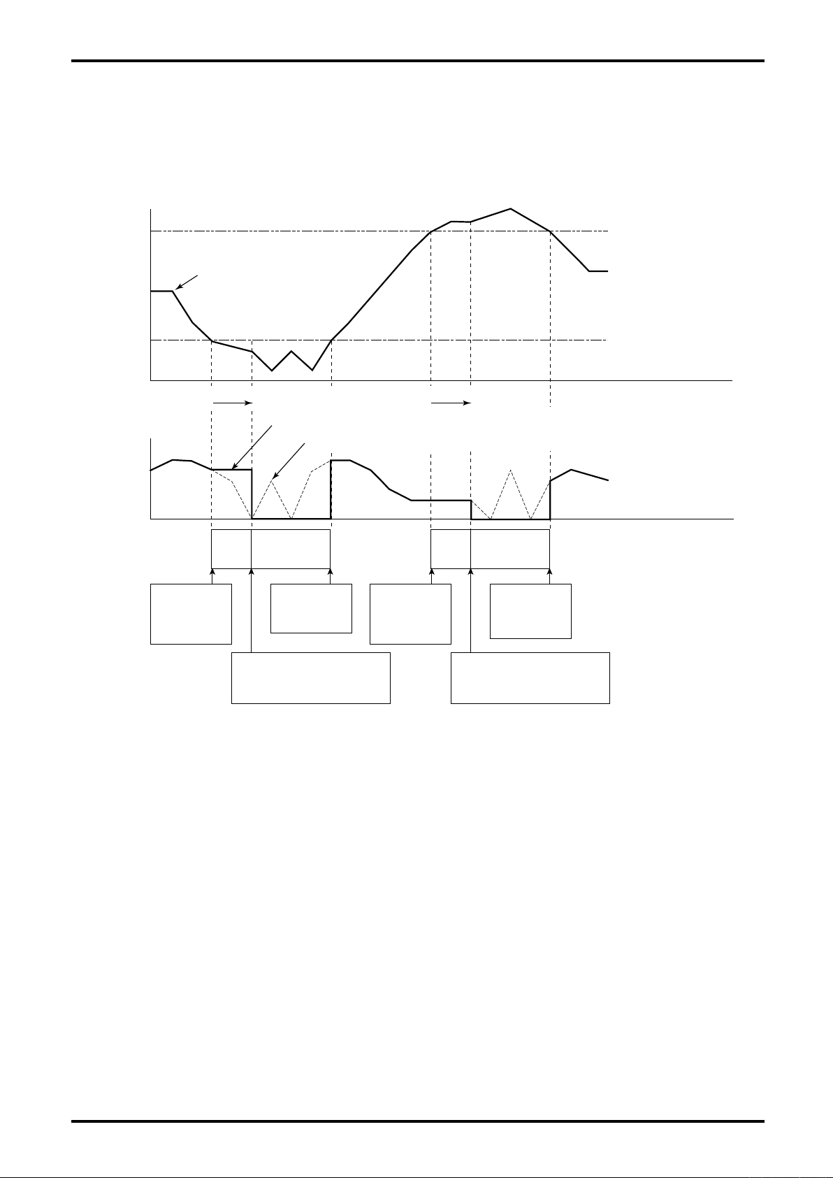
L-737-3-E
Time
Time
"Higher limit density [2.0]"
"Lower limit density [0.5]"
Slug flow
alarm active
Slug flow
under
test
Slug flow
alarm active
Slug flow
under
test
Density
2.0
0.5
0
0
Slug flow identifi- 10sec
cation time
Slug flow identifi- 10sec
cation time
Flowrate with slug flow alarm active
Flowrate with slug flow alarm inactive
Density fell below
high limit value;
slug flow test starts
with flow data
retained.
Alarm canceled
as density
exceeded low
limit value.
Density fell below low limit value; as
slug flow test duration expires, a slug
flow alarm is issued with flowrate
clamped at 0.
Density exceeded high limit value; as
slug flow test duration expires, a slug
flow alarm is issued with flowrate
clamped at 0.
Density exceeded
high limit value;
slug flow test starts
with flow data
retained.
Alarm canceled
as density fell
below high limit
value.
Density [g/mL]
Flowrate [kg/min]
(2) An example of settings and behavior
・Lower limit density value of slug flow: 0.5 [g/mL]
・Upper limit density value of slug flow: 2.0 [g/mL]
・Slug flow identification time: 10 [sec]
76
Page 77

9.18 Setup Units List
Measurement type No. Acceptable setup units LCD display
M-1 g/sec g/s
M-2 g/min g/min
M-3 g/hr g/h
M-4 kg/sec kg/s
M-5 kg/min kg/min
M-6 kg/hr kg/h
M-7 kg/day kg/d
Instant mass
flowrate
Instant volume
flowrate
Density
Temperature
M-8 MetTon/min Mt/min
M-9 MetTon/hr Mt/h
M-10 MetTon/day Mt/d
M-11 lb/sec lb/s
M-12 lb/min lb/min
M-13 lb/hr lb/h
M-14 lb/day lb/d
M-15 ShTon/min St/min
M-16 ShTon/hr St/h
M-17 ShTon/day St/d
V-1 ml/sec mL/s
V-2 ml/min mL/min
V-3 ml/hr mL/h
V-4 liter/sec L/s
V-5 liter/min L/min
V-6 liter/hr L/h
V-7 liter/day L/d
V-8 CuMtr/sec Cm/s
V-9 CuMtr/min Cm/min
V-10 CuMtr/hr Cm/h
V-11 CuMtr/day Cm/d
V-12 gal/sec ga/s
V-13 gal/min ga/min
V-14 ImpGal/min Ig/min
V-15 ImpGal/hr Ig/h
V-16 ImpGal/day Ig/d
V-17 CuFt/sec Cf/s
V-18 CuFt/min Cf/min
V-19 CuFt/hr Cf/h
V-20 bbl/sec bl/s
V-21 bbl/min bl/min
V-22 bbl/hr bl/h
V-23 bbl/day bl/d
D-1 g/ml g/mL
D-2 g/cc g/cc
D-3 kg/l kg/L
D-4 kg/CuMtr kg/Cum
D-5 lb/gal lb/gal
D-6 lb/CuFt lb/Cf
D-7 SGU SGU
T-1 ° C deg C
T-2 °F deg F
T-3 Kelvin Kelvin
T-4 °R deg R
L-737-3-E
77
Page 78
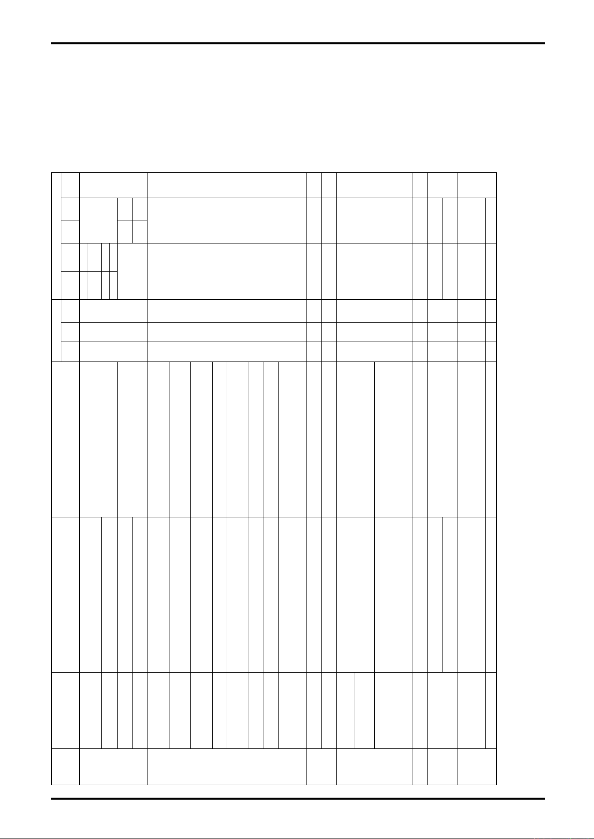
L-737-3-E
10. MAINTENANCE
In the event an error occurs, an error message appears at the bottom of LCD display. Make sure of its
nature. Sections 10.1 Error Messages and 10.2 Status Messages will assist you in identifying the cause
of trouble and finding necessary corrective action. If the problem persists, or if you have any question,
contact the factory.
10.1 Error Messages
utput
Per
Status
O
utput 2
Pulse
O
utput 1
Pulse
O
utput 2
Analog
O
Influences on output in an error
utput 1
Analog
21.6mA None
O
)
(※1
Backlight
ED
L
GRN
Indications in error
ED
L
RED
(※7)
select
status
None
11KHz
Unaffected
1.6mA
2
one
N
2.4mA None
None
11KHz
Unaffected
None 2.4mA
Blink ON OFF
er
P
elect
(※7)
s
status
etting
(※5)
er error
output
S
P
(※6)
Setting
Per error output
※4)
(
ORG
ON OFF
Status
Select (※7)
er error output
setting (※3, 5)
P
2.4mA Stopped OFF
er error output
setting (※3, 6)
P
RG
(※4)
(※4)
ORG
O
FF
OFF
O
N
O
Blink
(※2)
elect
(※7)
S
Status
etting
(※5)
output
s
Per error
(※6)
setting
Per error output
Blink ON OFF
tatus
S
Select
Status
Select (※7)
Clamped
Clamped
nly flow output
O
Blink OFF OFF Unaffected Unaffected
Blink ON OFF
elect
(※7)
Flow output at "0" Stopped
(※7)
S
Status
ontinued
C
ontinued
C
FF
O
N
O
FF
O
Blink ON OFF Continued Continued
Measurement is out of range. Adjust measurement
such that measurement selected falls within [lower
limit of analog output to upper limit value], or modify
setting. (※6)
Instant flowrate selected exceeds full scale flowrate
of pulse output. Lower instant flowrate for use or
increase full scale flowrate setting. (※5)
A fault in drive oil connections is a possibility. Verify
drive coil connections by self diagnostics.
(For details,see 9.6.2 Drive coil check.)
Mass flowrate exceeds the specification.
Use within the maximum allowable range.
A fault in temperature sensor is a possibility. Verify
0 to 110(%) range; failure
1
10 to 110(%) range; failure
-
Description Coping action
-
nalog output 1 out of
A
to produce proper output.
Analog output 2 out of
ulse output 2 exceeds 11kHz; failure to produce
to produce proper output.
Pulse output 1 exceeds 11kHz; failure to produce
proper output.
P
proper output.
Drive frequency out of normal range; failure to make
proper measurement.
Mass flowrate exceeds 110% of max. allowable
range; possible failure to make proper measurement.
Temperature out of normal range, failure to make
fault in pickoff sensor is a possibility. Verify pickoff
temperature sensor connections by self diagnostics.
(For details,see 9.6.3 Transmitter check.)
Bubble entrapment is a possibility.
Check for bubble entrapment.
A
proper measurement.
Density measured out of normal range (0 to 5[g/mL],
failure to make proper measurement.
Pickoff signal voltage out of normal range, failure to
fault in pickoff coil connections.
coil connections by self diagnostics.
(For details,see 9.6.3 Transmitter check.)
A fault in temperature sensor is a possibility. Check
make proper measurement.
A fault possible in temperature sensor wiring
onnections. (This error does not show up in
temperature sensor connections.
A
Check pickoff coil connections for condition.
A fault in drive coil connections. Check drive coil
c
fault possible in pickoff sensor wiring connections
onnections
c
A
fault in transmitter is suspected. Contact the
rive coil connections by self diagnostics.)
measurement. Upon error diction, be sure to verify
d
An error in parameters; inactive operation A fault in EEPROM is suspected. Contact the factory.
erify parameters and reconfigure to acceptable
A
factory.
V
values. (※6)
Upper limit < lower limit
fault in internal data
A
Parameter setting of analog output 1 or analog
output 2 comes under any of the following conditions
・
・Upper limit or lower limit > max. acceptable setting
alues. (For details, see 9.16 H/L Alarm Functions.)
Verify parameters and reconfigure to acceptable
v
Wait until the fluid flow settles down to a steady state
and retry zeroing.
Air entrapment in the fluid is a possibility. Verify the
fluid and line for conditions.
High ambient temperature cause a rise in the
tays on for a preset duration (slug flow check) upon
・Upper limit or lower limit < max. acceptable setting
H/L alarm parameter setting comes under any of the
following conditions
・High alarm < Low alarm
・High alarm or low alarm > max. acceptable setting
・High alarm or low alarm < max. acceptable setting
fter expiration of slug flow check duration upon gas
Auto zero offset (correction) is out of normal range.
S
detention of gas entrapment
A
entrapment detection
aulty switch operation. Contact the factory.
mbient temperature.
ransmitter’s internal temperature, leading to shorten
t
life of components. Take necessary step to lower
a
F
aulty operating switches
ransmitter’s internal temperature is unusual (above
T
80°).
F
Status
(Status display)
Analog Output 1
Saturated
(Ana. Out 1 Satur)
Analog Output 2 Saturated
type
Error
ulse Output 2 Saturated
(Ana. Out 2 Satur)
Pulse Output 1 Saturated
(Pls. Out 1 Satur)
P
(Pls. Out 2 Satur)
Drive Input Out of Range
(Drive OutOfRange)
Scale Over
(Scale Over)
Temperature Out of
Range
(Temp OutOfRange)
Density Outside Limits
(Density Outside)
P.O. Sig Error(P.O. Sig
Saturated
Alarm
Sensor
Failure
.O. Connect Error
emperature Connect Error
Err)
T
(Temp Connect Err)
P
(P.O. Connect Err)
Drive Coil Error A fault possible in drive coil wiring connections
ata Update Error
EEPROM Error
(EEPROM Err)
D
(Data Update Err)
Analog 1 Set Alarm
(Ana. 1 Set Alm.)
Analog 2 Set Alarm
(Ana. 2 Set Alm.)
H/L Alarm Point Set
Alarm
(H/L po.Set Alm.)
Auto Zero Failed
(Auto Zero Fail)
Transmitter
Failure
arameter
P
Alarm
ailure
Calibration
F
mtr Temperature Alarm
Slug Flow Alarm
(Slug Flow)
larm
Slug Flow
A
witch Alarm(Switch Alm.)
X
(Txr Temp Alm.)
S
2: In an alarm, the LED blinks at a faster rate (at intervals of 100ms) than in other alarms (at intervals of 250ms).
4: For 5 minutes after occurrence of an alarm condition (or sleep duration of backlight setting), the ORG backlight comes on; after which it will blink on and off.
Transmitter
Alarm
※1: Even with the run indicator staying off, the white backlight comes on in response to switch operation when backlight is set in the "ON" or "sleep".
6: For details,see 9.13 Analog Output Function.※7: For details,see 9.14 Status Output Function.
※
※3: Outputs can go uncontrolled under certain circumstances if the transmitter fails, however.
※
※5: For details,see 9.12 Pulse Output Function.
※
78
Page 79

10.2 A List of Status Messages
Status
Output
Pulse
Output 2
Unaffected
L-737-3-E
output)
Unaffected
(Set output
during simulated
Unaffected
Pulse
Output 1
Analog
Output 2
Analog
Output 1
Fixed output Unaffected
(※1)
Backligh
LED
GRN
Indications in error Influences on output in an error
LED
RED
Fixed output Unaffected
Unaffected
OFF Blink OFF
4mA Stopped Unaffected
Unaffected Unaffected Unaffected
OFF while ORG
indicator blinks at
operation startup
and shutoff.
OFF during the test
OFF Blink OFF Unaffected Unaffected Unaffected
Unaffected
(Set output during simulated output)
Unaffected
(Set output during simulated output)
OFF ON OFF Unaffected Unaffected Unaffected
OFF ON OFF Unaffected Unaffected Unaffected
OFF ON OFF Unaffected Unaffected Unaffected
OFF ON OFF Unaffected Unaffected Unaffected
OFF ON OFF Unaffected Unaffected Unaffected
Description
Analog output 1 fixed is active (※2)
Analog output 2 fixed is active (※2) Unaffected Fixed output
Pulse output 1 fixed is active (※2)
Pulse output 2 fixed is active (※2) Unaffected Fixed output
Status output fixed is active (※2) Unaffected Unaffected Fixed output
With a status input, 0% signal lock is active. (※2)
(Analog output clamped at 4mA with no pulse output.)
Auto zero in progress OFF Blink
H/L alarm occurred and is active.
(For details, see 9.16 High/Low Alarm Function.)
Drive output is exceeds the threshold. OFF Blink OFF Unaffected Unaffected Unaffected
Self diagnosis in progress OFF Blink OFF 0% Stopped Unaffected
Pipeline vibration check in progress OFF Blink OFF 0% Stopped Unaffected
Maintenance in progress OFF Blink OFF
If parameter change is made by switch operation while
the Key Protect was ON.
(If key operation is required, reconfiguration is needed.)
When the target parameter is changed or the operation
for executing the target function is carried out in Write
Protect mode.
When the number of run hours has exceeded 100,000
hours, it could lead to component failure or degradation.
We suggest transmitter replacement.
(You can cancel indicator ○.
See 9.2.7 Transition chart (6) [No. 4-3].)
Warmup in progress
(Stays on for 20 minutes upon power on. Countdown
value decrements at one (1) minute intervals.)
Poor power supply condition is a possibility. (A short
duration power cycling has occurred a couple of times.)
While there is no problem in continuation of operation,
we suggest to run a check for condition of power supply.
This message goes out automatically in 20 minutes.
Status
(Status display)
Analog Output 1 Fixed
(Ana. Out 1 Fix)
Analog Output 2 Fixed
(Ana. Out 2 Fix)
Pulse Output 1 Fixed
(Pls. Out 1 Fix)
Pulse Output 2 Fixed
(Pls. Out 2 Fix)
Status Output Fixed
(Status Out Fix)
0% Sig Lock
(0% Sig Lock)
Calibration in Progress
(Cal. in Progress)
H/L Alarm Triggered
(H/L Alm. Trig.)
Drive Out Alarm
(Drive Out Alarm)
Self Diagnosis
(Self-Diag)
Installation
(Installation)
Maintenance Test
(Maintenance Test)
Key Protect
(Key protect.)
Write protect.
Xmtr Operating-Time Over
("○" blinks at lower left of LCD)
Xmtr Warm up
(WARMUP 20)
Powr OK ?
Status type
Fixed Output
Calibration
Alam
Drive Out
H/L Alarm
in Prgress
Test
Operation
Transmitter
※1: Even with the run indicator staying off, the white backlight comes on in response to switch operation if backlight is set in the sleep mode.
※2: Simulated output is available irrespective of the state of alarm. (Certain types of error disables output, however.)
79
Page 80

L-737-3-E
10.3 Replacement Parts
We recommend to keep a stock of replacement parts in case anything goes wrong. Replacement parts
are available at the OVAL representative in your area. Please supply us with the flowmeter model, part
name, product number, and quantity when you order.
Interconnect cable (Teflon or PVC): Quantity 1
Replacement of parts such as o-rings and sheet packing for transmitter and terminal
box
O-rings and gaskets are used as sealing components with limited service life.
Although the exact service life depends on the operating environment, periodic replacement is
recommended. Recommended replacement period: 5 to 8 years after the delivery
CAUTION:
1. Whenever you open or disassemble the instrument, inspect the O-rings
and gaskets. Replace the deteriorated parts.
2. To ensure the soundness, periodic re-torquing of the corresponding parts
is recommended.
Corresponding parts:
Transmitter: O-ring between display lid (front) - body
Transmitter: O-ring between terminal box lid (rear) - body
Transmitter: Sheet packing between side lid - body
Transmitter: O-ring between adopter - body (Integral type only)
Transmitter: O-ring on sensor unit (Integral type only)
O-ring between terminal box - lid (Separate type only)
Cable gland: rubber seal and O-ring
Please contact the OVAL sales office when replacement is necessary
80
Page 81
10.4 Explosionproof specification
(1) ATEX, IECEx Explosionproof
●
Integral type
• Transmitter symbol: Ⅱ2G Ex d ib ⅡC T4 Gb • Detector symbol: Ⅱ2G Ex ib ⅡC T4
• Transmitter and detector ambient temperature: −40℃ to +55℃
• Fluid temperature: −40℃ to +80℃
●
Separate type
• Transmitter symbol: Ⅱ2G Ex d [ib] ⅡC T6 Gb
• Transmitter ambient temperature: −40℃ to +55℃
Detector ambient temperature −40℃ to +60℃
Fluid temperature
Temperature class: T3 −40℃ to +130℃
Temperature class: T4
(2) KCs Explosionproof
●
Integral type
• Transmitter symbol: Ex d ⅡC T4 • Detector symbol: Ex ib ⅡC T4
• Transmitter and detector ambient temperature: −40℃ to +55℃
• Fluid temperature: −40℃ to +80℃
●
Separate type
• Transmitter symbol: Ex d[ib] ⅡC T6 • Detector symbol: Ex ib ⅡC T3, T4
• Transmitter ambient temp.: −40℃ to +55℃ • Communication: HART, Modbus
Detector ambient temperature −40℃ to +60℃
Fluid temperature
Temperature class: T3 −40℃ to +130℃
Temperature class: T4
• Communication: HART, Modbus, PROFIBUS and FOUNDATION fieldbus (FISCO)
• Detector symbol: Ⅱ2G Ex ib ⅡC T3, T4
• Communication: HART, Modbus, PROFIBUS and FOUNDATION fieldbus (FISCO)
−40℃ to +80℃
• Communication: HART, Modbus
−40℃ to +80℃
L-737-3-E
(3) CSA Explosionproof
●
Integral type
• Transmitter symbol: Class I, Zone 1, Ex d ib ⅡB T4 Gb • Detector symbol: Class I, Zone 1, Ex ib ⅡB T4 Gb
Class I, Zone 1, AEx d ib ⅡB T4 Gb (Integral type) Class I, Zone 1, AEx ib ⅡB T4 Gb
• Transmitter and detector ambient temperature: −40℃ to +55℃ • Communication: HART, Modbus, PROFIBUS and FOUNDATION fieldbus (FISCO)
• Fluid temperature: −40℃ to +80℃
●
Separate type
• Transmitter symbol: Class I, Zone 1, Ex d [ib] ⅡB T6 Gb • Detector symbol: Class I, Zone 1, Ex ib ⅡC T3, T4 Gb
Class I, Zone 1, AEx d [ib] ⅡB T6 Gb Class I, Zone 1, AEx ib ⅡC T3, T4 Gb
• Transmitter ambient temp.: −40℃ to +55℃
Detector ambient temperature −40℃ to +60℃
Fluid temperature
Temperature class: T3 −40℃ to +130℃
Temperature class: T4
• Communication: HART, Modbus, PROFIBUS and FOUNDATION fieldbus (FISCO)
−40℃ to +80℃
(4) GOST Explosionproof
●
Integral type
• Transmitter symbol: 1 Ex d ib ⅡC T4X • Detector symbol: 1 Ex ib ⅡC T4
• Transmitter and detector ambient temperature: −40℃ to +55℃ • Communication: HART, Modbus
• Fluid temperature: −40℃ to +80℃
●
Separate type
• Transmitter symbol: 1 Ex d [ib] ⅡC T6X • Detector symbol: 1 Ex ib ⅡC T3, T4
• Transmitter ambient temp.: −40℃ to +55℃ • Communication: HART, Modbus
Detector ambient temperature −40℃ to +60℃
Fluid temperature
Temperature class: T3 −40℃ to +130℃
Temperature class: T4
−40℃ to +80℃
(5) NEPSI Explosionproof
●
Integral type
• Transmitter symbol: Ex d ib ⅡC T4 Gb • Detector symbol: Ex ib ⅡC T4 Gb
• Transmitter and detector ambient temperature: −40℃ to +55℃ • Communication: HART, Modbus
• Fluid temperature: −40℃ to +80℃
●
Separate type
• Transmitter symbol: Ex d [ib] ⅡC T6 Gb • Detector symbol: Ex ib ⅡC T3, T4 Gb
• Transmitter ambient temp.: −40℃ to +55℃ • Communication: HART, Modbus
Detector ambient temperature −40℃ to +60℃
Fluid temperature
Temperature class: T3 −40℃ to +130℃
Temperature class: T4
−40℃ to +80℃
81
Page 82

L-737-3-E
10.5 Precautions on the explosionproof specification
10.5.1 About the explosionproof
Special conditions to use the explosionproof equipment safely:
- Prohibition of altering the part constituting the explosionproof performance
Part constitutes the flameproof: Display (glass) – body/terminal lid – parts screwed on the body
Side lid – spigot joint of the body
- Special class of the fastening screw to fix the side lid shall be “A-50”.
- Transmitter shall be used only in the position specified in the instruction manual.
- The cable gland shall be screwed in for at least 8 threads completely.
- Electric capacitance of the label shall be 1nF max. and to avoid charging of static electricity. Use a
wet cloth to clean the label.
10.5.2 About handling of the flameproof enclosure
The enclosure of the transmitter is a flameproof configuration. In order to maintain the explosionproof
performance, due attention to the followings is required.
- About the part screw applied of the flameproof enclosure:
The part screw applied of the flameproof enclosure is the critical part to maintain the explosionproof
performance. Hence, due care is required so that such part is not damaged or foreign materials are
not mixed in. If any damages or such are found, please contact our service center.
- About side lid (bonded surface of spigot joint) of the flameproof enclosure:
Side lid (bonded surface of spigot joint) of the flameproof enclosure is the critical part to maintain
the explosionproof performance. Normally, opening this part by user is prohibited. If it is accidentally
opened in maintenance or such, do not damage it and avoid having foreign materials in it. Tightening
screws of strength class A-50 are used on the side lid. In case of replacement or missing, please
contact our service center.
About cable gland:
82
Page 83

L-737-3-E
CAUTION
Cautions in assembling
(1) : Putting the cable through rubber packing, screw in the gland and press the packing. In this,
make sure to screw in the gland enough until the cable stops.
(2) : This cable gland is furnished with a hook. After (1), make sure to screw in the clamp with a
M4 screw and fix the cable.
■ ATEX, IECEx explosionproof, KOSHA/KTL explosionproof and CSA explosionproof
1. Normally, cable glands are not supplied by OVAL. In case they are prepared by each customer,
make sure to use the cable gland which conforms to following requirements.
Explosionproof code:Exd ⅡCU
Protection class: IP66 min.
Nominal size: G3/4
2. Optionally, cable glands can be supplied by OVAL. According to the OD of cable used, select the
proper size that is suitable for rubber packing.
Model code: SXE-22
Nominal size:G3/4
Applicable cable OD
Packing OD Cable OD
φ12 φ11 to φ12
φ13 φ12 to φ12.9
φ14 φ13 to φ13.9
Unit: mm
NOTE: 1. In case of ATEX, IECEx, use Ex component.
2. In case of KOSHA/KTL, use KCS marked component.
3. In case of CSA, use NRTL approvals(Class I, Zone 1, AEx d IIB and over)
component.
◆ Tighten up the part firmly so as not to have clearance between the cable and rubber packing.
◆ If there are any electric conduits not used, seal them properly with the pertaining close-up plug
supplied by OVAL to prevent intrusion of rain water and dust.
Model code :SBP-22
Nominal size:G3/4
83
Page 84
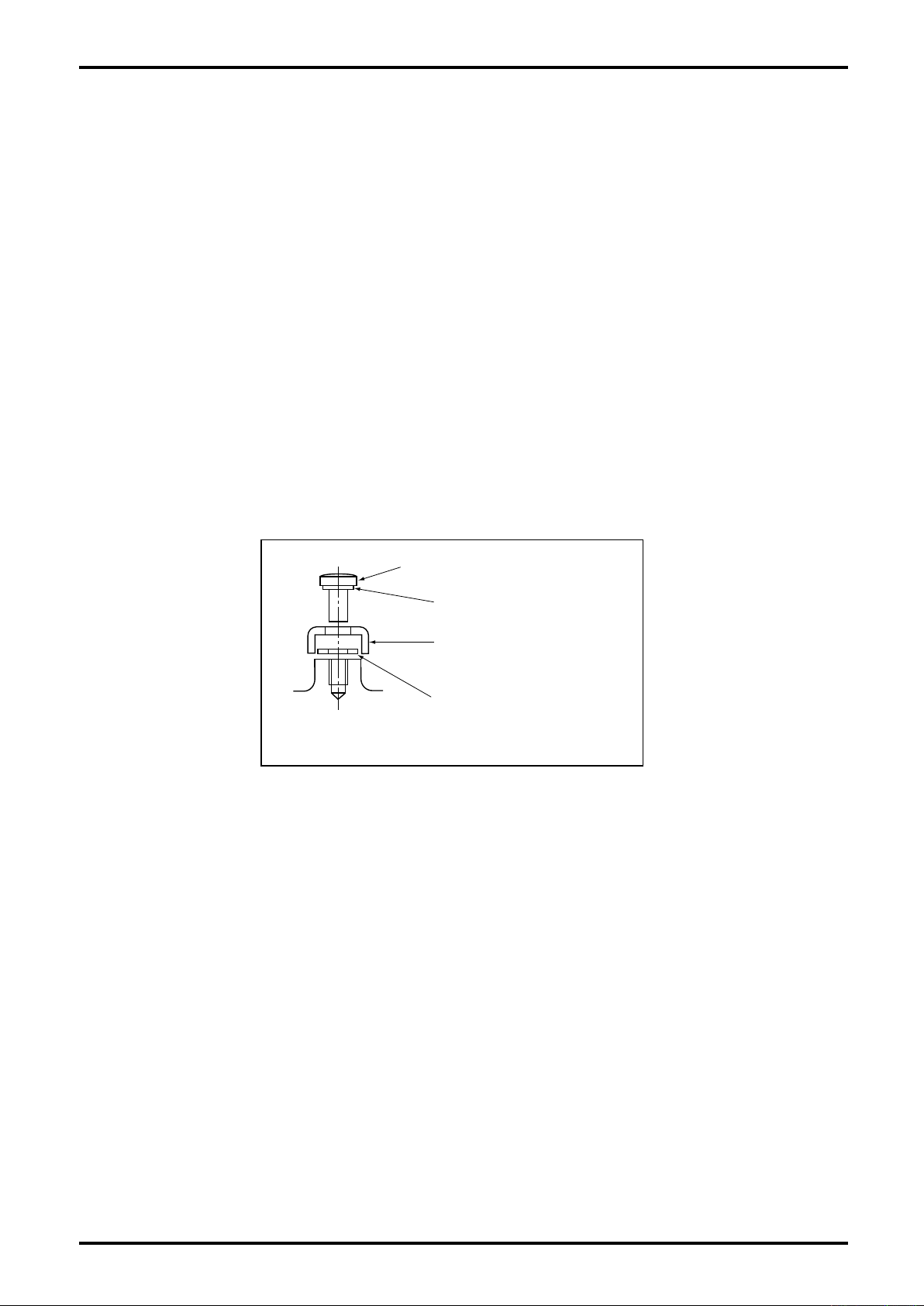
L-737-3-E
Spring washer
Earth terminal cover
Plain washer
Cross recess pan head screw
10.5.3 Insulation performance
Part of transmitter (PA0K) subject to insulation:
IS circuit terminals (separate detector board: TB20, TB21) - Enclosure
Withstand voltage condition: 500VAC, leak current: 3 to 5mA
Due to the built-in noise eliminator between the transmitter power source terminals (TB1’s L and N) and
output terminals (TB2, TB3 and TB4), and the enclosure respectively, complete insulation is not provided.
In case withstand voltage test is conducted across these parts, please conduct under the conditions
below.
Withstand voltage condition: AC200V or DC250V, leak current: 3 to 5mA
10.5.4 Earthing terminal
1. Use GND of power source terminal block or any of external grounding terminals.
2. Use wires of cross section area of 4mm2 min. (AWG11 min.) for grounding.
3. Coating color of the grounding wires shall be green or stripe of green and yellow.
4. Class D grounding (100 ohm or less) is recommended.
5. In case external wirings are used, make sure that the grounding wire is connected with the earth
terminal cover and plain washer in the sketch below.
Fig.10.2
10.5.5 About dedicated cable (for only separate type)
1. In case of separate type, a dedicated cable is used for connection between the sensor and
transmitter. Use of other cables are not allowed from the point of explosionproof.
2. Make sure to array the dedicated cable between the sensor and transmitter so that any current and
voltage, which attributable to electromagnetic induction or electrostatic induction and could impair
the intrinsic safety performance of the IS circuit, is never induced.
84
Page 85

L-737-3-E
10.5.6 Maintenance and checking
In order to use OVAL’s Coriolis Flowemters for long period of time, please perform inspection and
maintenance according to the following items. Also, make sure to check and inspect the Flowmeter while
de-energizing without hazardous gas in the surrounding area.
Check item Description Check
General
Grounding
Sensor
Transmitter
Is the dedicated cable being used ?
If it is having a mixed touch with other cables, particularly with power supply
lines ?
If the coating is damaged or peeling off ?
Is the dedicated cable properly connected ?
Is the terminal end properly treated ?
Is the separation cover installed ?
Is the lid for the terminal box installed ?
Are bolts and hex socket set screws for fastening the transmitter loose ?
Is the grounding made properly ?
Is the screw for the grounding terminal loose ?
If the grounding wires are deteriorated ?
Drive circuit resistance: Resistance range: 50 to 5kΩ *1
Pick-off circuit resistance: Resistance range: 60 to 600Ω *1
Temp. sensor circuit resistance: (100+0.385×Temp.) Ω
*1: There are some differences depending on each sensor and fluid temp.
*2: This measurement is possible only with the separate type. If measured at
the transmitter side, the interconnection resistance of dedicated cable is
added.
If any of the connections of display lid, terminal lid or side lid are loose ?
If the part tightened up of cable gland loose ?
Is the packing of the cable gland discolored, hardened, torn, or cracked ?
Is the enclosure and glass deformed or has crack or such ?
*Paint is not regarded to be enclosure.
About handling of grease on bonded surfaces:
If short and deterioration of the grease on the parts below are found through normal use, replenish grease
properly. For this purpose, periodic check is recommended.
85
Page 86
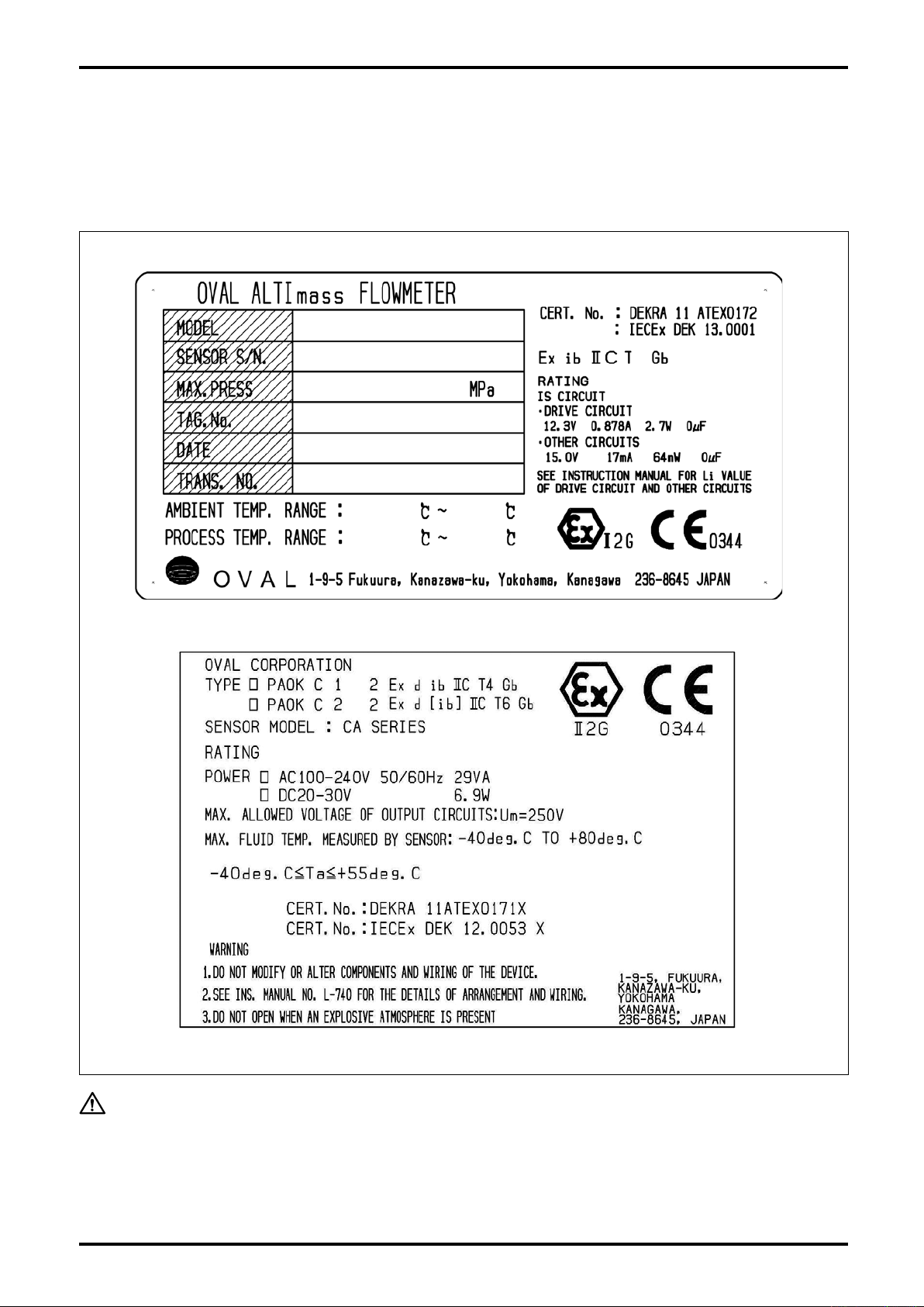
L-737-3-E
11. EX-INFORMATION
11.1 Nameplates
Explosionproof pertinent information is described on the label attached on the product.
SENSOR SIDE
TRANSMITTER SIDE
Fig.11.1
WARNING:
86
1. Do not modify or alter components and wiring of the device.
2. See Section 7.10 Wiring Diagram for the details of arrangement and wiring.
3. Do not open the lid in the explosive atmosphere.
Page 87
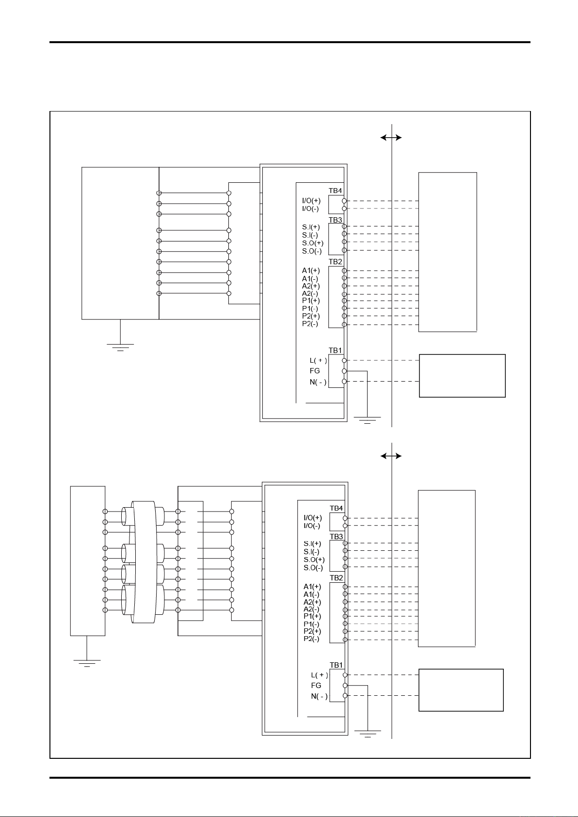
11.2 System Block Diagram (Control Drawing)
HART Communication and Modbus Communication
Integrally mounted transmitter
(INTRINSICALLY SAFE APPARATUS)
CA004
(INTRINSICALLY SAFE RELATED APPARATUS)
DETECTOR BOARD
PA0K
TERMINAL BOX
L-737-3-E
HAZARDOUS AREA NON HAZARDOUS AREA
GENERAL APPARATUS
EXTERNAL
CIRCUIT
Separately mounted transmitter
CA004
(INTRINSICALLY
SAFE APPARATUS)
DEDICATED CABLE
(TERMINAL BOX FOR INTRINSICALLY
SAFE EXPLOSIONPROOF)
SEPARATE DETECTOR BOARD
FLAMEPROOF ENCLOSURE (d)
HAZARDOUS AREA NON HAZARDOUS AREA
(INTRINSICALLY SAFE RELATED APPARATUS)
DETECTOR BOARD
PA0K
TERMINAL BOX
EXTERNAL
CIRCUIT
POWER
AC100-220V 50/60Hz
or
DC20-30V
GENERAL APPARATUS
FLAMEPROOF ENCLOSURE (d)
Fig.11.2.1
POWER
AC100-220V 50/60Hz
or
DC20-30V
87
Page 88
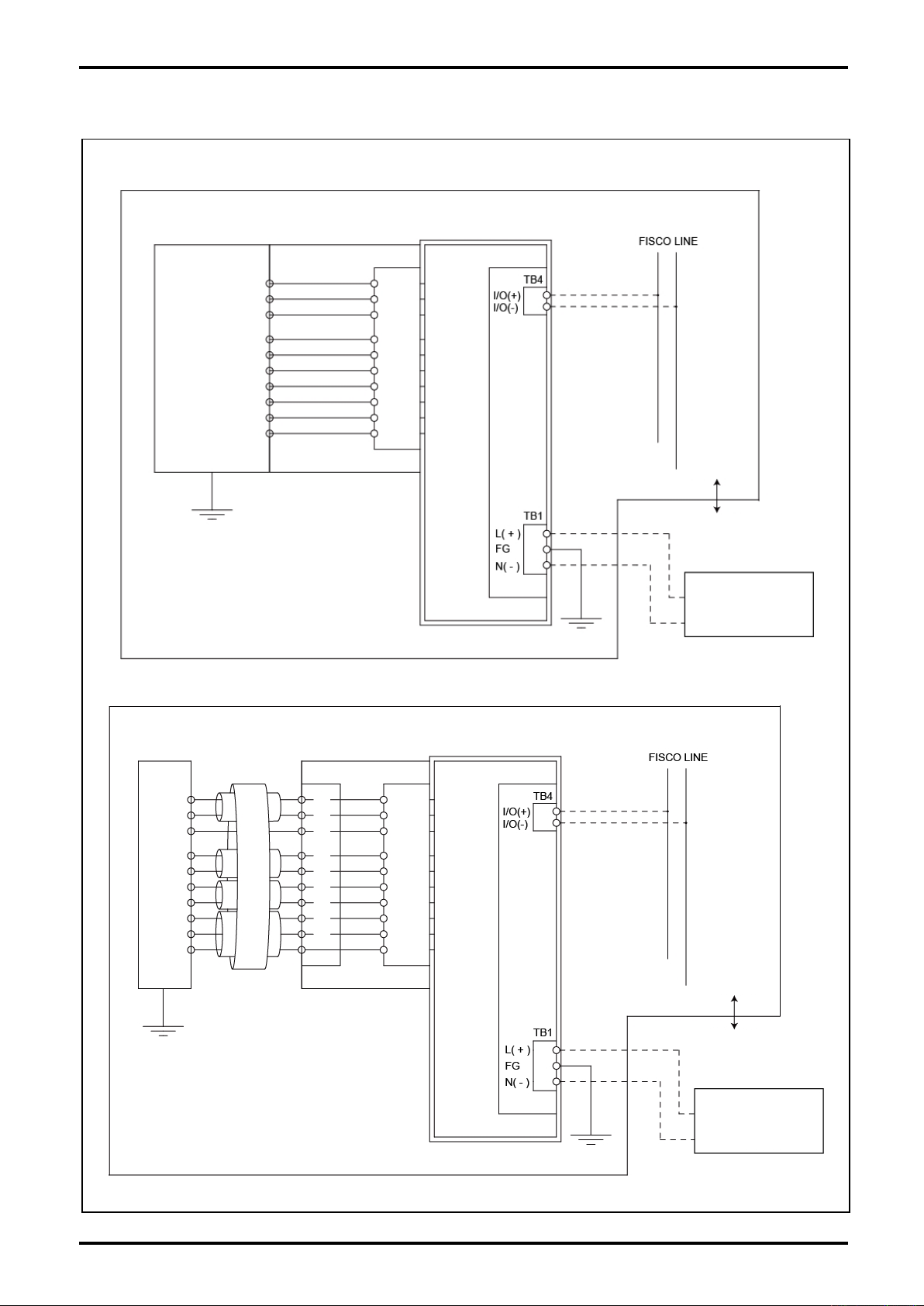
L-737-3-E
FOUNDATION fieldbus communication and PROFIBUS communication
Integrally mounted transmitter
(INTRINSICALLY SAFE APPARATUS)
CA004
(INTRINSICALLY SAFE RELATED APPARATUS)
DETECTOR BOARD
PA0K
TERMINAL BOX
FLAMEPROOF ENCLOSURE (d)
EXTERNAL
CIRCUIT
HAZARDOUS
AREA
NON HAZARDOUS
AREA
POWER
AC100-220V 50/60Hz
or
DC20-30V
Separately mounted transmitter
CA004
(INTRINSICALLY
SAFE APPARATUS)
DEDICATED CABLE
(TERMINAL BOX FOR INTRINSICALLY
SAFE EXPLOSIONPROOF)
SEPARATE DETECTOR BOARD
TERMINAL BOX
DETECTOR BOARD
FLAMEPROOF ENCLOSURE (d)
EXTERNAL
CIRCUIT
HAZARDOUS
AREA
NON HAZARDOUS
AREA
POWER
AC100-220V 50/60Hz
or
DC20-30V
88
Fig.11.2.2
Page 89
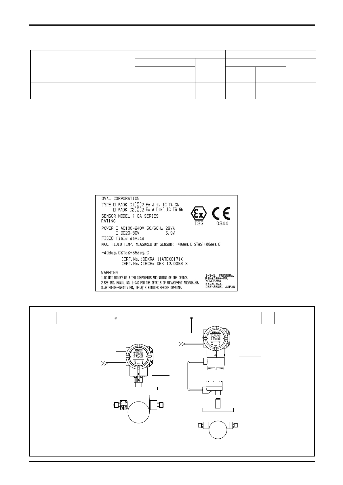
11.3 Inductance and Internal Resistance of Sensor Coil
INTEGRAL MODEL
SEPARATE MODEL
POWER
POWER
TRANSMITTER
Ex d [ib
]
Ex d ib
Ex i
SENSOR
Ex ib
T
BUSLINE(FISCO)
Drive circuit Circuits other than drive circuit
Sensor model
Drive coil
Li max
(mH)
R min
(Ω)
Drive
Resistance
(Ω)
Pickoff coil
Li max
(mH)
R min
(Ω)
L-737-3-E
Pickoff
resistance
(Ω)
CA004□1□XX□□□□□□□□
33.7 377.0
—
3.6 69.0
—
Do not perform a repair involving the explosionproof construction. If servicing is necessary, contact your
nearest OVAL sales office or sales representative.
11.4 Regarding FISCO System of FOUNDATION fieldbus and PROFIBUS
If the 16th digit of product code is“2 : FOUNDATION fieldbus (FF), Communication Specification”or
“3 : PROFIBUS, Communication Specification”, the transmitter is compatible with Intrinsic Safety
(IEC60079-11 Annex G).
Below are the allowable parameters of ALTImass transmitter:
Ui=17.5V, Ii=380mA, Pi=5.32W , Ci=negligible low, Li=10μH
Transmitter label to show the FF and PROFIBUS specifications
Bus Line Connection Diagram
Fig.11.3
89
Page 90
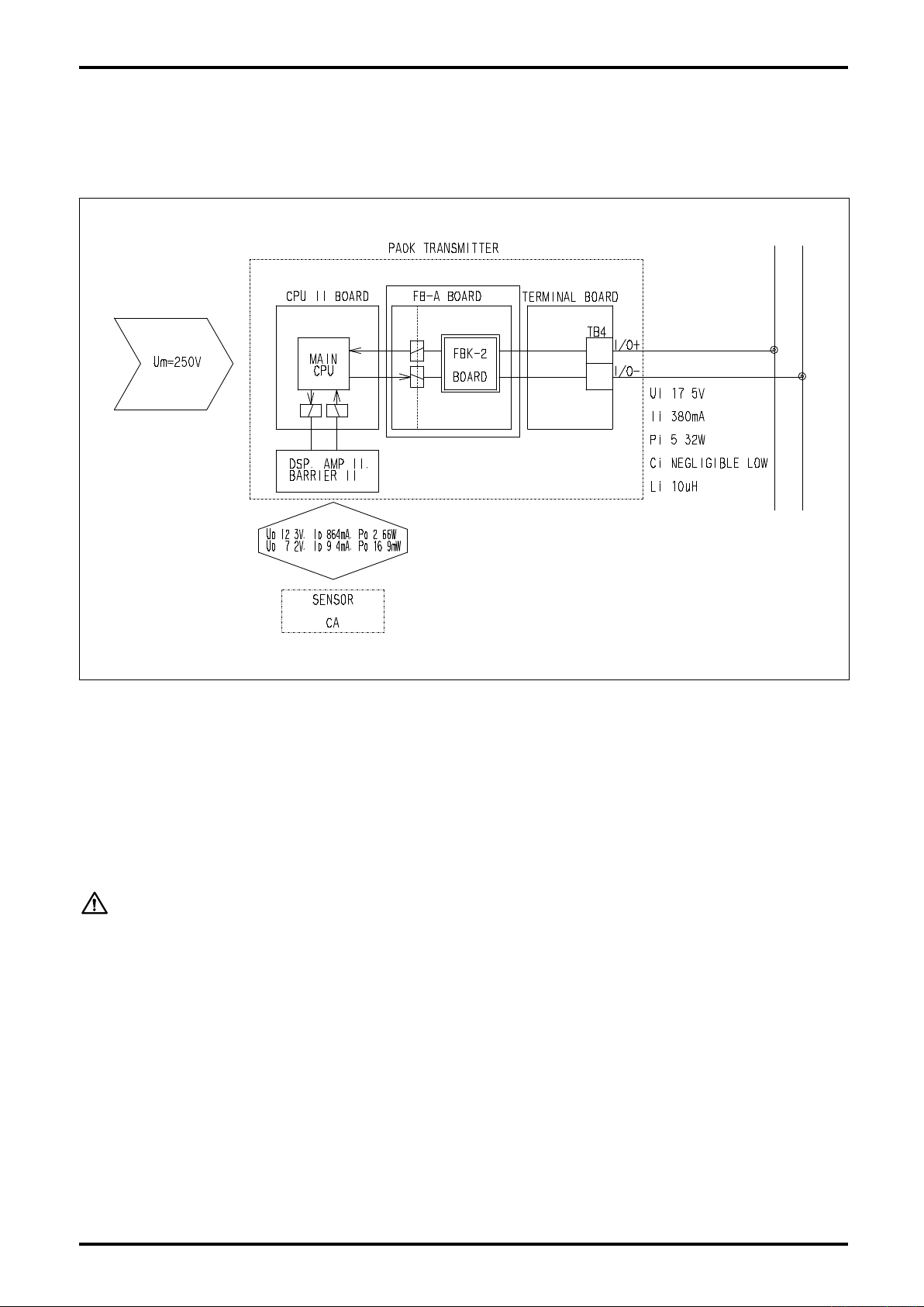
L-737-3-E
System Configuration
Connect the bus lines of FISCO System to I/O+ and I/O- of the transmitter communication signal terminal
board TB4. (Drawing below)
BUS LINE
(FISCO)
FF Unit or PROFIBUS Unit
Galvanic Isolation
Fig.11.4
[Configuration of FISCO Explosion Protection]
The transmitters with FF Communication Specification and PROFIBUS Communication Specification are
connected to bus line via TB4 (I/O+, I/O -) of terminal board but the voltage applied from bus line to the
non-intrinsic safety circuit in the transmitter is separated (galvanically isolated) at FF Unit or PROFIBUS
Unit. Accordingly, please conform to the warning below in order to assure the establishment of FISCO
Explosion Protection when using FF or PROFIBUS Communication.
WARNING:
Do not use analog output, pulse output and status when FF Communication
or PROFIBUS Communication is active. Do not perform wiring, either.
90
Page 91
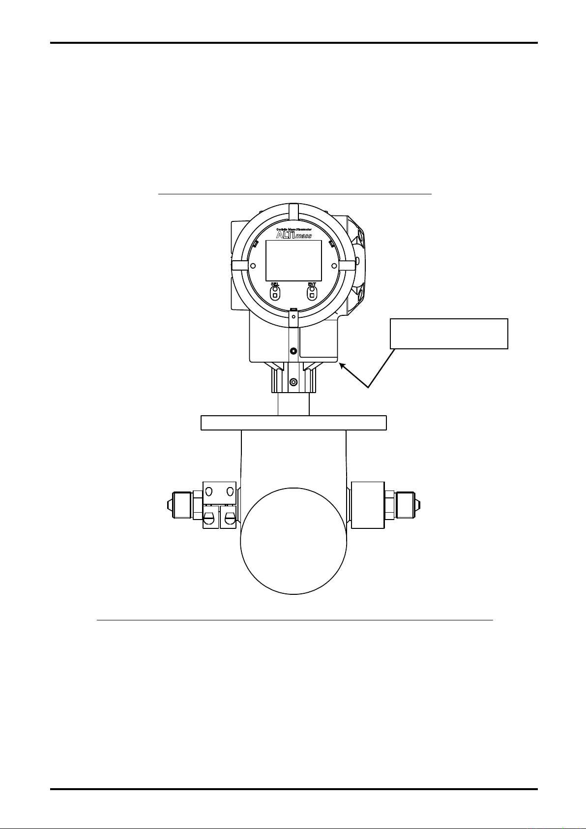
L-737-3-E
Explosionproof applied
temperature location
Explosionproof applicable temperature: +59.0℃
Location of the part subject to explosionproof applicable temperature
11.5 Explosionproof Applicable Temperature (Integrally Mounted Type Only)
The integrally mounted explosionproof transmitter of ALTImassⅡ adopts “Explosionproof applicable
temperature”.
Whenever this instrument is used in explosive atmosphere, temperature must be controlled so that the
temperature of the part subject to explosionproof applicable temperature shown below never exceeds the
specified temperature.
91
Page 92
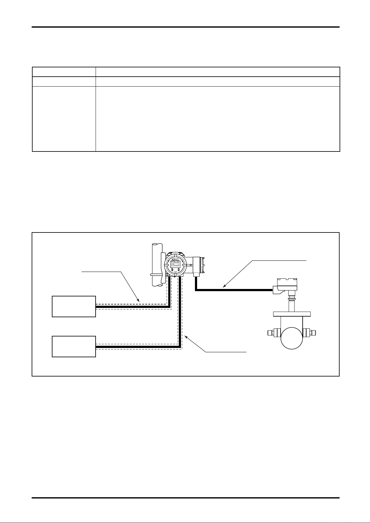
L-737-3-E
DedicatedCable
PowerCable
SignalCable
Power
Source
Receiver
12. ABOUT MARITIME CERTIFICATION
ALTImass transmitter is approved of the maritime certification under below conditions:
Item Contents
Classification Society DNV GL
Temperature D (-25℃ to +55℃ )
Humidity B (Relative Humidity: less than 100%)
Vibration A
Location Classes
※ Install at the place where mechanical vibration from engine,
compressor, pump and so on is not introduced into transmitter
directly.
EMC A (All locations except bridge and open deck)
Enclosure C (IP56)
Regarding Cable Wiring
If using ALTImass as certified equipment for maritime applications, use metal conduit tube, marine cable
(with shield), etc. for the power and signal cables and connect shielded sections to the transmitter
housing.
Be sure to use the dedicated cable for the connection between the sensor and the transmitter, and
implement waterproofing treatment which satisfies IP56.
(2 to 13.2Hz with 1mm amplitude, 13.2 to 100Hz with 0.7g acceleration)
92
Fig.12.1
Page 93
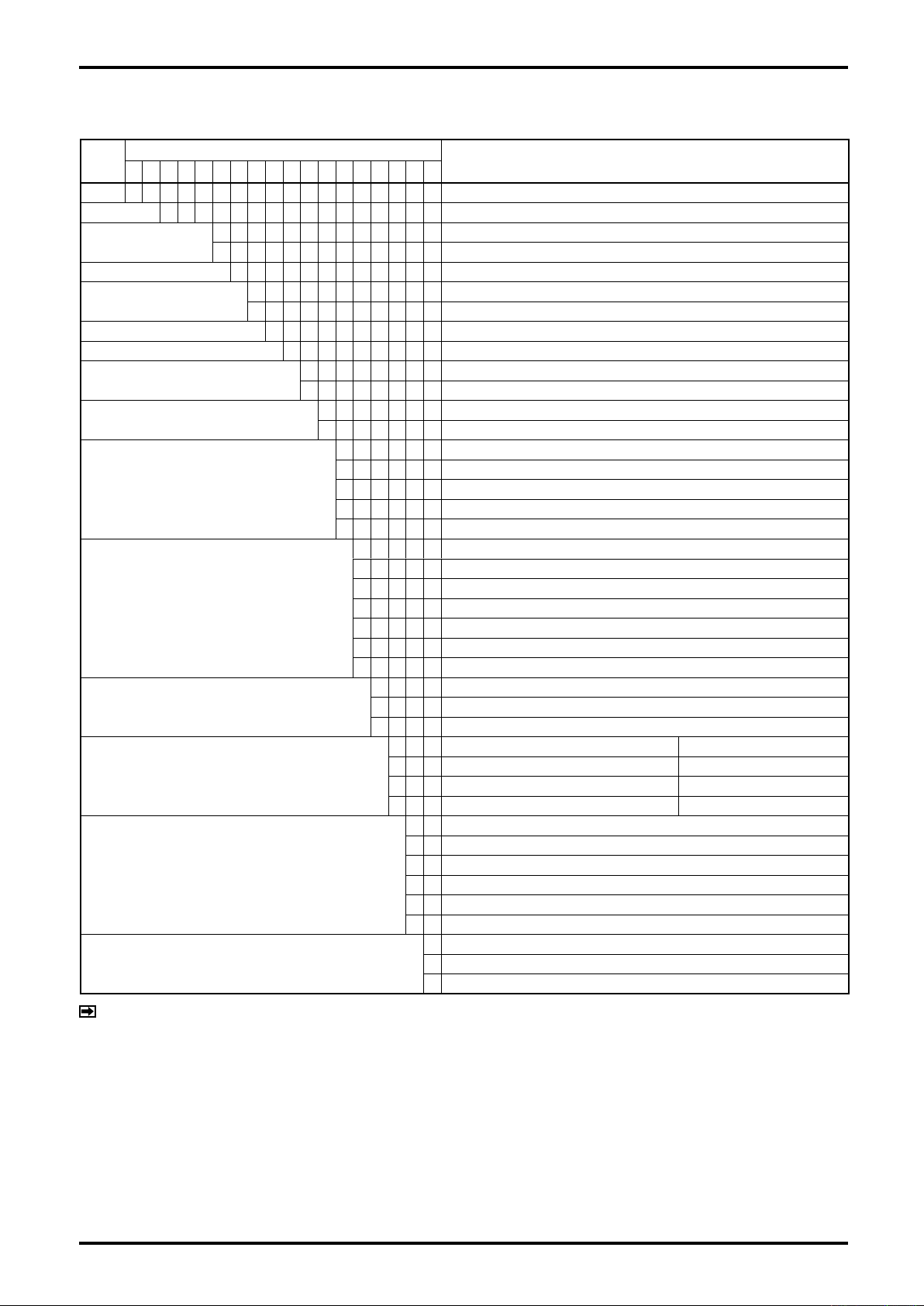
13. PRODUCT CODE EXPLANATION
L-737-3-E
Item
① ② ③ ④ ⑤ ⑥ ⑦ ⑧ ⑨ ⑩ ⑪ ⑫ ⑬ ⑭ ⑮ ⑯ ⑰ ⑱
C A ALTI
Model
Nominal size
Fluid category
Temperature category (※1)
Pressure category
Major parts material
Process connection
Transmitter construction
Power source
Analog output
Pulse output
Pulse output type
Communication interface
Explosionproof rating
Explosionproof temperature class
0 0 4 9/16″
Product Code
L
G Gas
1
1 120MPa max.
3 120MPa with a rupture disk (Option)
X TPXM-19
X High-press. Cone & Thread
1
2
1 20 to 30VDC
2 85 to 264VAC (Safety rated 100 to 240VAC) 50/60Hz
A
C
E
K
X
A
C
D
F
H
K
X
0
1
2
mass
Liquid
Standard (below 130°C)
Integrally mounted
Separately mounted
Output 1: Mass flow Output 2: Mass flow
Output 1: Mass flow Output 2: Temperature
Output 1: Mass flow Output 2: Volume flow (fixed density)
Output 1: Volume flow (fixed density) Output 2: Temperature
Non-output In the case of FOUNDATION fieldbus, PROFIBUS communication
Output 1: Mass flow
Output 1: Volume flow (fixed density)
Output 1: Mass flow Output 2: Mass flow
Output 1: Mass flow Output 2: Volume flow (fixed density)
Output 1: Volume flow (fixed density) Output 2: Volume flow (fixed density)
Output 1: Volume flow (fixed density) Output 2: Mass flow
Non-output In the case of FOUNDATION fieldbus, PROFIBUS communication
Non-output In the case of FOUNDATION fieldbus, PROFIBUS communication
Open drain pulse (equivalent to open collector pulse) (standard)
Voltage pulse
1
2
3
4
HART communication
FOUNDATION fieldbus H1 communication (※2)
PROFIBUS PA communication (※2)
Modbus communication RS-485 Modbus protocol
0
Non-explosionproof
2 ATEX, IECEx
3 KCs (※3)
4 CSA
5 GOST (※3)
7 NEPSI (※3)
0
Non-explosionproof
3
Sensor unit: Temp. class T3, separate transmitter only
4
Sensor unit: Temp. class T4
Description
Type U
Bell202
ITR version 6
Profile version 3
NOTES
※1: Explosionproof specifications are restricted based on temperature class.
※2: When FOUNDATION fieldbus, PROFIBUS is selected for communication interface, product code categories of analog
output is "X" and pulse output is "X" (pulse output type:"0").
※3: "2" and "3" for the product code ⑯ are not available. (in preparation)
93
Page 94
L-737-3-E
■ Shipping Parameters
Given below is the explanation of parameters found in the parameter list attached to the product.
No. Item Name Factory setting Setting
Transmitter information (Device Info)
1 Tag Tag No.
2 Descriptor Description
3 Message Message
4 Date Date of manufacture
5 Dev ID Device ID
6 Final asmbly num Serial No.
7 Snsr s/n Sensor serial No.
8 Snsr model Sensor model
9 Flange Flange rating
10 Snsr matl Sensor material
11 Hardware rev Hardware revision
Sensor information (Sensor Type)
12 Sensor type Sensor type
13 Mass flow USL Max. allowable rang
14 Mass flow LSL Min. allowable range
15 Temperature USL Max. allowable temperature range
16 Temperature LSL Min. allowable temperature range
Flow information (Flow)
17 Mass flow unit Instant mass flow rate unit
18 Vol flow unit Instant volume flow rate unit
19 Flow Direction Flow direction select
20 Damp Flow rate (mass) damping
21 Flow cutoff Flow rate (mass) cutoff
22 Vol flow coef Volume flow correction coefficient
Density information (Density)
23 Unit Density unit
24 Damp Density damping
25 Slug low limit Lower limit density, slug flow identification
26 Slug high limit Higher limit density, slug flow identification
27 Slug duration Slug flow identification duration
28 Density compensation Run reference temp. conversion setting
29 Standard temp Reference temperature
30 Expansion coef Expansion coefficient
31 Set density Run fixed density conversion setting
32 Density value Fixed density value
Temperature information (Temperature)
33 Unit Temperature unit
34 Damp Temperature damping
Analog output 1 information (Analog Output 1)
35 Assign Analog output 1 assignment
36 URV 20mA setting, analog output 1
37 LRV 4mA setting, analog output 1
38 Lowcut Low flow cutoff, analog output 1
39 Added damp Added damping, analog output 1
Analog output 2 information (Analog Output 2)
40 Assign Analog output 2 assignment
41 URV 20mA setting, analog output 2
42 LRV 4mA setting, analog output 2
43 Lowcut Low flow cutoff, analog output 2
44 Added damp Added damping, analog output 2
Continued on next page➡
94
Page 95
Pulse output 1 information (Pulse Output 1)
45 Assign Pulse output 1 assignment
46 Freq factor Full scale frequency, pulse output 1
47 Rate factor Full scale flow rate, pulse output 1
48 Lowcut Low flow cutoff, pulse output 1
Pulse output 2 information (Pulse Output 2)
49 Assign Pulse output 2 assignment
50 Freq factor Full scale frequency, pulse output 2
51 Rate factor Full scale flow rate, pulse output 2
52 Lowcut Low flow cutoff, pulse output 2
Status input/output information (Status Input/Output)
53 Input function Function select, status input
54 Input mode Input mode select, status input
55 Output function Function select, status output
56 Output mode Output mode select, status input
High/low alarm information (H/L Alarm)
57 Assign High /low alarm assignment
58 H/L alarm type High/low alarm type select
59 High alarm point Higher limit alarm value
60 Low alarm point Lower limit alarm value
61 H/L alarm hys High/low alarm hysteresis value
Error information (Error Select)
62 Sensor failure
63 Transmitter failure
64 Calibration failure
65 Saturated alarm
66 Parameter failure
67 Transmitter alarm
68 Slug flow alarm
69 Calibration in progress
70 Fixed output
Output in an error information (Error Output)
71 Analog Analog output pattern in an error
72 Pulse Pulse output pattern in an error
Flow factor information (Flow Cal)
73 SK20 Meter factor of flow rate
74 SKM Meter error correction term
75 SKt Flow rate correction factor (Skt)
76 Cal temp Temperature during flow calibration
77 Cal freq Frequency during flow calibration
78 SKfa Flow correction factor (Skfa)
79 SKfb Flow correction factor (Skfb)
80 FKt Flow correction factor (Fkt)
Density factor information (Density Cal)
81 Dens (Water) Density during density calibration
82 Cal temp Temperature during density calibration
83 Cal freq Frequency during density calibration
84 Freq coef β Density correction coefficient
Output select in individual item
L-737-3-E
95
Page 96
L-737-3-E
SAFETY STATEMENT ON RETURNED GOODS
When you return your Coriolis flowmeter for repair or other processing, send us a fax of this Safety Statement
and, at the same time, attach it to the equipment to be returned for our need to provide a safe working
environment to our employees.
Unless the Safety Statement on Returned Goods is attached to the returned equipment, or if we find it difficult
to ensure safety, we may decline, at our discretion, to accept and process the returned equipment.
(In case some residual metered fluid may be present in the housing, consult the factory.)
Equipment to
be returned
Model
Serial No.
List all chemicals and process fluids in c ontact with the equipment.
Process Fluid
Names
If an MSDS is available, attach here.
Health and Safety
Hazards
If an MSDS is available, attach here.
Precautions
(First aid)
NOTE: MSDS stands for Material Safety Data Sheet. It informs us of the physical and
chemical properties of materials and how to handle them.
I hereby certify that the equipment being returned has been cleaned and decontaminated in accordance with
good industrial practices. This equipment poses no health or safety risks due to contamination.
Sensor Unit Transmitter
Company Name
Address
Phone No. Fax No.
Job Title
Signature by
Reason for return
Remarks
Date:
96
Page 97

Company name
Address
Contact
Return (shipping)
L-737-3-E
REPAIR REQUEST SHEET
Reason for repair (type
of order)
Delivery date Date of installation
Date of failure
◆ Unless the statements below are fully documented, returned equipment will not be processed.
Equipment Sensor Unit Transmitter
Model
Serial No.
Connections
Power supply
Flange pressure rating
Process conditions
Process fluid name
(chemical formula)
Temperature
Pressure
Range change data □YES □No Initial serial No. □YES □No
□Repair □Calibration □Replacement □ Return
□Others
Output (mA) Output (frequency)
Pressure input Pressure output
□Tube empty (no obstacles)
Sensor conditions
Type of cleaning material used for sensor unit
□Sensor empty (no obstacles)
□Tube clogged/contaminated
◆IMPORTANT
If the tube leaks, make sure that no process fluids remain in the housing. To provide a safe working
environment for our employees and engineers, this form must be filled in completely and accurately.
Unless accurate and precise information about the process fluids is given, returned equipment will
NOT be processed. Include your instructions and conditions accurately and in detail.
NOTE: To avoid misunderstanding, completely fill in this form.
97
Page 98

L-737-3-E
All specifications are subject to change without notice for improvement.
2017.02 Revised△
2016.11 Released
L-737-3-E (1)
 Loading...