

Oval 50, 55, 56, 57, 52 Instructions Manual
...
Ins. No.
B-149-4N-E
High Temp./Low Temp. Service and Jacketed
SMART ULTRA OVAL FLOWMETERS
Meter Sizes 50, 52, 53, 55, 56, and 57
Meter size 50
Cooling tube provided
Meter sizes 52, 53, 55, 56
Meter size 57
Cooling tube provided
Every SMART ULTRA OVAL is fabricated and shipped from our factory under stringent quality control. In
order to maintain its design performance throughout the life of the meter, this manual offers the operator the
necessary installation, operation and maintenance information.
Be well familiar with these instructions before you place the meter in service and keep this manual at the eld
location for ready reference.
The standard, high temperature-service, low temperature-service, and jacketed type meters all have in
common the same specifications described in this instruction manual except for some differences in the
jacketed type on its piping procedure and operating precautions. Be careful to observe the instructions given
with a reminder "See also page 15 for the jacketed type".
About Meter Size Designation
◆
The size of OVAL positive-displacement owmeters is basically identied by a two-digit code. For complete
details, see Section 17 PRODUCT CODE EXPLANATION.
◆
Heating tube provided
1

B-149-4N-E
CONTENTS
1. BEFORE YOU BEGIN ........................................................................................................................4
1.1 Conrming the Tag .........................................................................................................................4
1.2 Transportation Considerations .......................................................................................................4
1.3 Storage Considerations .................................................................................................................4
1.4 Structural Considerations ..............................................................................................................5
2. OPERATING CONDITIONS ...............................................................................................................5
3. GENERAL DESCRIPTION .................................................................................................................6
4. PART NAMES .....................................................................................................................................6
5. LCD COUNTER DISPLAY ..................................................................................................................7
5.1 About "MODE" Switch ................................................................................................................... 7
5.2 Display Functions ........................................................................................................................... 7
5.3 Display Mode Selection .................................................................................................................7
5.4 Total Counter Reset ........................................................................................................................8
5.5 Considerations with Pulse Output Type ......................................................................................... 8
6. INSTALLATION ................................................................................................................................... 9
6.1 Considerations at Installation ......................................................................................................... 9
6.2 Standard Installation, Horizontal Line ............................................................................................9
6.3 Standard Installation, Vertical Line
6.4 Example of Faulty Piping ...............................................................................................................9
7. HOW TO CHANGE FLOW DIRECTIONS ........................................................................................10
8. WIRING INSTRUCTIONS ................................................................................................................11
8.1 Wiring Guidelines ........................................................................................................................11
8.2 Terminal Connections ...................................................................................................................11
8.3 Preamplier-to-Receiving Instrument Hookup ............................................................................. 12
9. OPERATING INSTRUCTIONS .........................................................................................................13
9.1 Operation .....................................................................................................................................13
9.2 Operating Precautions .................................................................................................................13
9.3 Precautions at Operation Shutdown ............................................................................................14
9.4 About Register Life ......................................................................................................................14
9.5 Piping Instructions and Operating Precautions of Jacketed Meters ...........................................15
10. DISASSEMBLY AND INSPECTION ...............................................................................................16
10.1 Size 50 Meter Body Disassembly and Inspection ......................................................................16
10.2 Size 50 Meter Body Assembly Procedure .................................................................................17
10.3 Sizes 52, 53, 55, 56, 57 Meter Body Disassembly and Inspection ............................................18
10.4 Sizes 52, 53, 55, 56, 57 Meter Body Assembly Procedure ........................................................19
........................................................................................................................................... 9
11. REGISTER SWITCH FUNCTIONS AND PARAMETER SETTING ................................................ 20
11.1 Switch Names and Functions ....................................................................................................20
11.2 Individual Test Pin Functions ......................................................................................................21
11.3 About Meter Factor .................................................................................................................... 21
2
B-149-4N-E
12. SENSOR REPLACEMENT PROCEDURE .....................................................................................22
13. TROUBLESHOOTING ....................................................................................................................23
14. EXPLODED VIEWS AND PARTS LIST .......................................................................................... 24
14.1 Meter Size 50 Exploded View and Parts List .............................................................................24
14.2 Meter Sizes 52 and 53 Exploded View and Parts List ...............................................................25
14.3 Meter Sizes 55 and 56 Exploded View and Parts List ...............................................................26
14.4 Meter Size 57 Exploded View and Parts List .............................................................................27
15. GENERAL SPECIFICATIONS ........................................................................................................28
16. OUTLINE DIMENSIONS ................................................................................................................29
17. PRODUCT CODE EXPLANATION .................................................................................................30
CONVENTIONS
Shown in this manual are the signal words NOTE, CAUTION and WARNING, as described in the
examples below:
NOTE: Notes are separated from the general text to bring the user's attention to
important information.
CAUTION: Caution statements signal the user about hazards or unsafe practices
which could result in minor personal injury or product or property damage.
WARNING: Warning statements signal the user about hazards or unsafe practices
which could result in severe personal injury or death.
3
B-149-4N-E
NAMEPLATE
(RATINGS SHOWN)
1. BEFORE YOU BEGIN
Every Smart Ultra OVAL is thoroughly tested before it leaves the factory. When received, it should be thoroughly
inspected for indication of rough handling during transit. Necessary handling precautions are described in this
section; read the instructions carefully.
As for other information, nd the respective sections from "CONTENTS" on pages 2.
For any inquiries, contact your nearest OVAL designated sales ofce.
CAUTION: When you make inquiries, include the product name, model number,
product number, ratings and other pertinent information.
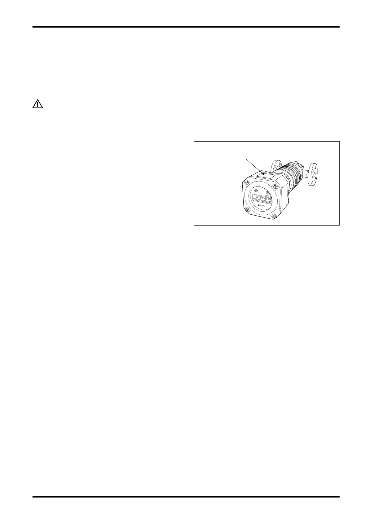
1.1 Confirming the Tag
Every Smart Ultra OVAL is assembled and adjusted
ac cordi ng to indivi dual s pec ifications. Produ ct
code number and ratings are stated on the register
tag. Make sure that, by referring to the general
specifications on pages 28 and the product code
explanation on page 29, the ratings shown conform
to your particular specication.
1.2 Transportation Considerations
(1) To safeguard against damage during transit, transport your Smart Ultra OVAL to the installation site in the
same container used for transportation from the factory if circumstances permit.
(2) Smart Ultra OVAL is adjusted and inspected as an assembly consisting of the meter body, sensor and
register. It should therefore be handled as an integral assembly.
(3) The register is accurately congured and adjusted. Do not attempt to remove the front cover to gain access
to its internal assembly.
1.3 Storage Considerations
If your Smart Ultra OVAL is stored for long periods of time upon receipt before installation, unexpected faulty
conditions could result. If a long-term storage is anticipated, take the following precautions:
(1) Keep your Smart Ultra OVAL in store in the same shipping container used for transportation from OVAL if
possible.
(2) Place of storage should conform to the following requirements:
- Free from rain and water.
- Free from vibration and impact shocks.
- Temperature and relative humidity in the storage place are at or near room temperature and humidity
(3) Purge the Smart Ultra OVAL that has once been placed in service with clean air, N2 gas, etc. to prevent the
metered uid from adhering to the meter connections, piping inner walls, housing, etc. before storage. (Wash
clean with suitable detergent if necessary.)
(4) In case of storage for extended periods of time, good practice is to keep in store in the same containers
used for shipment from the factory.
(around 25°C and 65%).
4
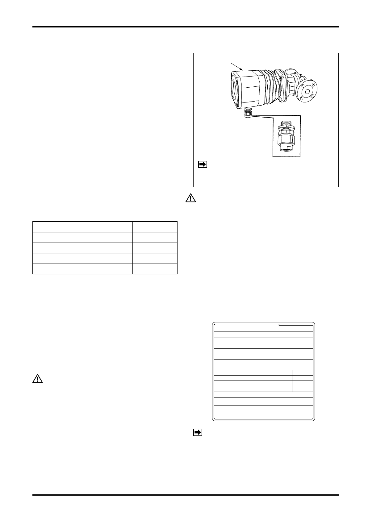
1.4 Structural Considerations
Register
Cable Lead-in
(Pressure-resistant
packing)
ULTRA OVAL
MADE IN JAPAN MNPJ-237
OVAL Corporation
MODEL
TAG. No
MAX PRESS.
FLOW RANGE
INT.
CONT.
~
~
FULL SCALE
TEMP.
PULSEUNIT
SERIAL No.
FLUID
DATE
SIZE
METER FACTOR
NOTES
1. When measuring other liquids, consult us.
2. Place the meter body (outer case) in a horizontal
position. For details, see instruction manual.
(1) The register is of waterproof construction for
outdoor service.
(2) The register is type approved. Do not attempt to
replace component parts with others or make
any circuit modication.
(3) The pressuretight packing furnished constitutes
pa rt of the fla mepro of construction . Do not
attempt to use any pressuretight packing other
than those furnished. The pressuretight packing
union s h o u l d be ti g h t e n e d s e c u r e l y up o n
completion of connections.
(4) Of the four different p re ssure tight packings
(φ9,
10, φ11 and φ12) furnished as standard
φ
accessories, a
in place.
Sele c t from t h e s e and insta l l the one that
best fits the finished outside diameter of your
particular cable.
Table 1.1 Applicable Cable Outside Dia. Unit in mm
Packing Code Packing I.D. Cable O.D.
9 9.0
10 10.0 9.1 to 10.0
11 11.0 10.1 to 11.0
12 12.0 11.1 to 12.0
11 packing is tentatively installed
φ
8.5 to 9.0
B-149-4N-E
NOTE:
CAUTION
Moisture allowed into the register wil cause
blurred display glass and functional trouble.
Pr e c au t i o n s o n cab l e l e a d - i n fit t i ng
(pressuretight packing), both explosionproof
and non-explosionproof models:
- Use a pressuretight packing that fits the finished
cable O.D.
- Tighten up properly to allow no clearance between
the pressuretight packing and the cable.
- If a pressuretight packing is not used, apply some
waterproof treatment to preclude any chance of
moisture getting into the equipment.
P r e s s u r e t i g h t p a c ki n gs a re n o t
supp l i ed with n onexplo s ionpro o f
models.
2. OPERATING CONDITIONS
To ma intain the sta ted hig h a ccuracy and lon g
servic e life o f SM ART ULTR A O VA L flowme ter,
make sure that owrate, pressure, temperature and
viscosity are within the ratings as stamped on the
meter register nameplate. Do not fail to confirm
these ratings before placing it in service.
CAUTION
1. Although allowable ambient temperature is
up to +60 °C for explosionproof units, it is
desirable that the meter be used at room
temperature and humidity.
2. In cases where the register is exposed to
elevated temperatures due to exposure to
direct rays of the sun or to radiant heat,
ensure, by providing a sunshade or similar
protection, that the meter is used within
the operating temperature range.
NOTE: Avoid such installation locations where
1. Not easy to access for servicing.
2. Large temperature variation and vibration.
3. Potential risk of submersion in water.
4. Corrosive gas atmosphere.
5. Not compatible with ex. construction.
6. Near sources of strong magnetic noises.
5
B-149-4N-E
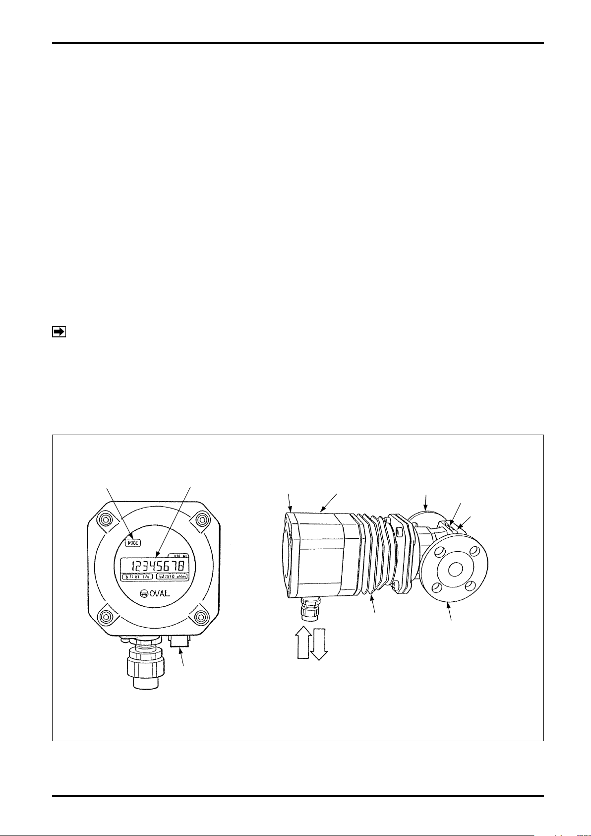
MODE SWITCH LCD COUNTER
FRONT COVER REGISTER
FLOW DIRECTION
REAR COVER
SELECTOR
MAGNET
CONNECTING
FLANGE
METER BODY
COOLING TUBE
(OR HEATING TUBE)
PRESSURETIGHT
PACKING
POWER
SIGNAL
3. GENERAL DESCRIPTION
Smart Ultra OVAL has been developed to meet the needs of precise owrate measurement. The local direct-
reading total counter is an all-electronic register built around a single-chip CPU. With the latest electronic
technologies used throughout, this versatile register displays accumulated total ow, instantaneous owrate
(digital readout) and provides, by option, a pulse and analog output proportional to the rate of ow.
In this meter, uid ow is detected by sensing with an amorphous sensor the magnetic elds of permanent
magnets embedded in the oval rotors. As a result, high reliability is achieved.
Features
(1) Absence of any mechanically sliding components except for oval rotors contributes to long service life.
(2) Small wetted parts count and pocketless design makes this meter ideally suited for ow measurement of
chemical liquids.
(3) You can monitor accumulated total ow and instantaneous owrate locally on the digital display.
(4) When coupled with a remotely located receiving instrument, output signals can readily and simply be used
for applications including control, adjustment and recording.
(5) IEC explosionproof construction offers increased safety and the design is compact.
(6) A nonvolatile memory, both in the local totalizer type and externally powered type meters, retains
accumulated total in the event of power failure or when de-energized.
NOTE:
If you have any request, contact the supplier you purchased the product or our sales ofce.
With the use over an extended period of time, meter error will deviate more or less from the initial
point. Upon request, we may conduct an instrumental error testing once again and establish a
"new meter factor" in the scaler when your Smart Ultra OVAL is returned to the factory for periodic
inspection or for other reasons.
4. PART NAMES
Fig. 4.1
6
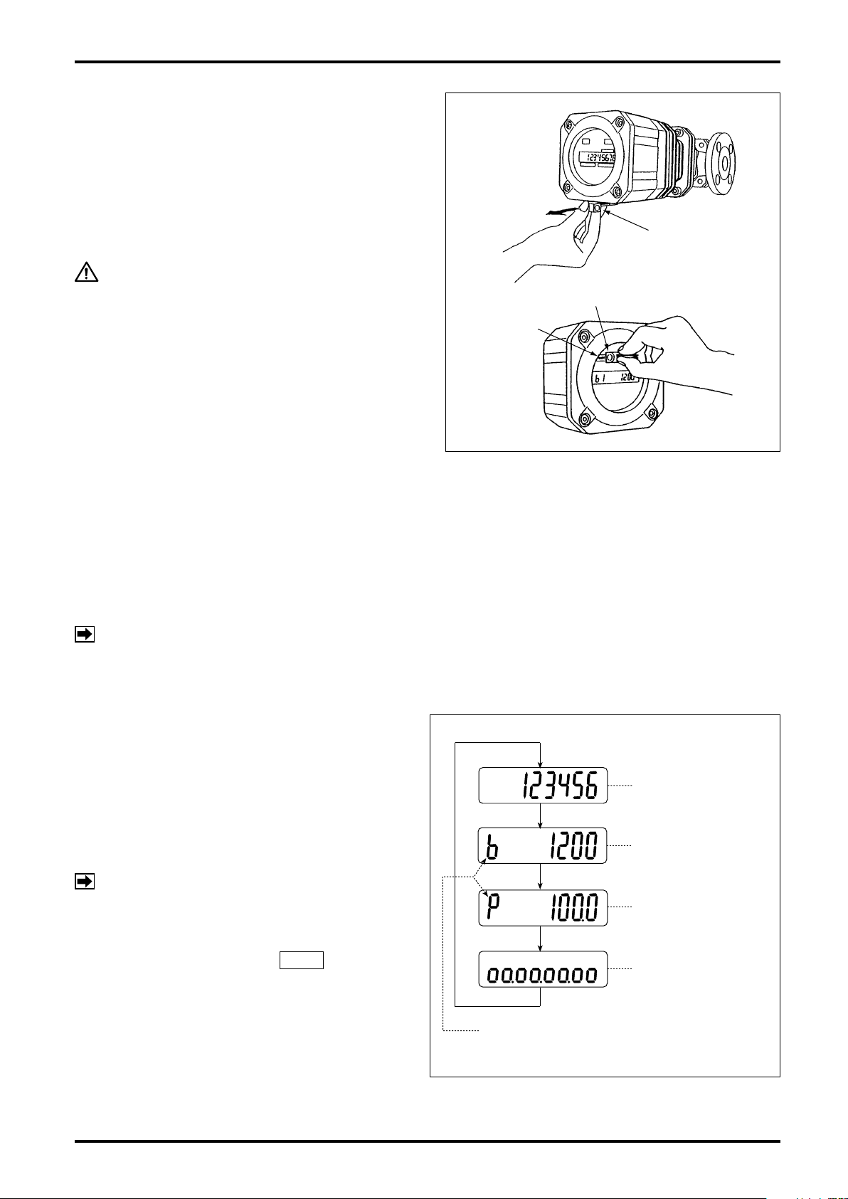
5. LCD COUNTER DISPLAY
SELECTOR MAGNET
SELECTOR MAGNET
"MODE"
EXAMPLE OF READINGS
MODE SYMBOL
TOTALIZED FLOW
INSTANTANEOUS
ACTUAL FLOWRATE
% INSTANTANEOUS
FLOWRATE
8-DIVISION
BAR GRAPH
5.1 About "MODE" Switch
Rem ovin g the sele ctor magn et ins erte d at the
bottom of the register, apply it to the label "MODE"
on the LCD counter face and the display will scroll
forward through the available readings as shown in
Fig. 5.1.
CAUTION
Do not fail to return the selector magnet
to its holder after use lest you will not
lose it. It uses an intensive magnet; never
hold it close to floppy disks or other
magnetic storage media.
B-149-4N-E
5.2 Display Functions
The display can show four different kinds of ow information - total ow, instantaneous actual owrate, percent
instantaneous owrate, and 8-division percent bar graph.
It also shows the following error messages:
Full scale exceeded : ErrorFS
Upper-limit owrate exceeded : ErrorOF
NOTE: Multiple errors will be indicated in priority order below:
ErrorOF > ErrorFS
5.3 Display Mode Selection
Two ways are available to select displays - with a
display select switch inside the register, or through
communications with the Smart Communication Unit
Model EL2310 (or HHC: Model EK10).
If your option is through communications, follow the
instructions outlined in the Smart Communication
Unit EL2310 (or HHC: EK10) instruction manual.
NOTE: Show "Measure" window at "View" menu
on the PC screen.
Selection with display select switch requires access
to the display sel ect switch SW1 by open ing
the register cover facing its internal assembly and
pressi ng this switch (see page 20) . T he display
scrolls forward through available information each
time you press this switch as shown in Fig. 5.1.
Fig. 5.1
7
B-149-4N-E
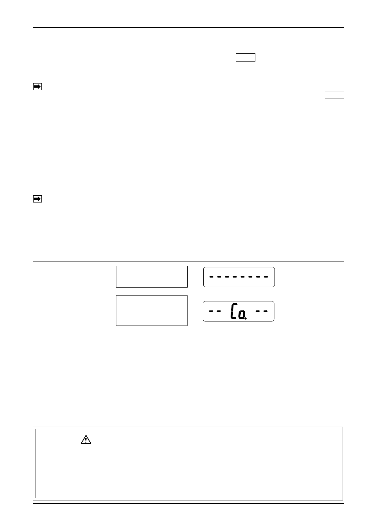
②
①
15 seconds after power on.
(Com Standby Mode)
Communication is started
within 15 seconds after
power on. (Com Mode)
5.4 Total Counter Reset
Displayed total flow can be reset either by the display select switch SW1 (see Fig. 11.1 on page 20) or
through communications with the Smart Communication Unit. It your option is through communications, follow
the instructions outlined in the Smart Communication Unit EL2310 (or HHC: EK10) instruction manual.
NOTE: Show "Measure" window at "View" menu on the PC screen.
With the display select switch, then, you can reset the totalizer by holding the display select switch SW1
depressed for more than 3 seconds while the total ow is shown.
5.5 Considerations with Pulse Output Type
(1) If your model is of pulse output type, the pulse output and total counter remain inoperative for 15 seconds
approx. after power on and while communications with the Smart Communication Unit continue. For 15 seconds
approx. after termination of communications, the pulse output and total counter also remain inoperative.
(2) Requirements for validating communications
Communications are made valid only when the following requirements are met:
- Flowrate at zero (There is no pulse output.)
- Within 15 seconds after power turn-on
NOTE:
If communications are started during this time period, a switchover to "Communication mode" takes
To start ow measurement routine, turn power on again. (After power cycling, the pulse output and
The period of 15 seconds immediately after power on is called "Communication standby mode." (The
built-in indicator, if so equipped, will display as shown in
place, permitting you to communicate until power is turned off the next time. (The built-in indicator
will display as shown in ② in the gure below.)
total counter will also remain inoperative for 15 seconds.)
in the gure below.)
①
(3) While communications continue, the receiving instrument (total counter, etc.) may overcount under certain
circumstances. To eliminate the possibility of such erratic extra counting, precautions should be taken by
either disconnecting the receiving instrument before starting communications, or recording the most recent
total reading and other important data on paper.
(4) Except for the purpose of communications, do not attempt to connect the probe of Smart Communication
Unit with the signal lines. If the probe remains connected, the influence of capacitive impedance the
interface has could go to the point of producing distorted signals in waveform and, as a result, the receiving
instrument would fail to receive pulse signals accurately.
The analog type permits communications with the Smart Communication Unit at any
time. However, if, in an attempt to alter current parameters, the meter is configured
by mistake such that the new parameters are incompatible with the specification,
re sultan t sharp change s in out put may d istur b the b ehavio r of the rece iving
instrument. It is good practice, therefore, to make parameter changes while the fluid
flow is at zero.
8
Fig. 5.2 Display in Response to Power ON, Pulse Output Type
CAUTION: PRECAUTIONS with ANALOG OUTPUT TYPE
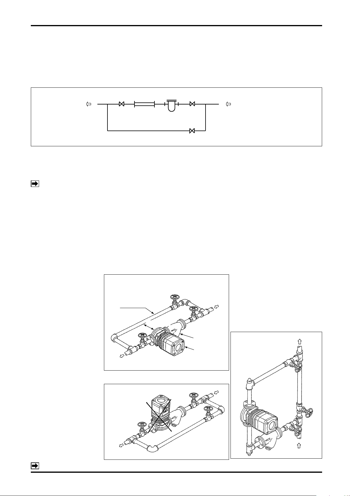
6. INSTALLATION
BYPASS LINE
STRAINER
VALVE
SHORT PIPE
FLOW
DIRECTION
OUT
IN
A
B
BYPASS
STRAINER
ULTRA OVAL
OU
T
IN
*(1100mm)
WRONG!
OUT
IN
B-149-4N-E
6.1 Considerations at Installation
"See also page 15 for the jacketed type".
(1) Flush the piping assembly.
Flushing must be performed before meter installation. Install a short pipe in place of the meter at this time (see
diagram below).
(2) Install the meter free from pipe strains.
(3) The meter must be installed on the discharge side of the pump.
(4) If the meter is to be used under tank head, give a head pressure greater than the losses with the piping
system, strainer, meter, etc.
NOTE: Pressure losses of the Smart Ultra OVAL and strainers are stated in the GENERAL SPECIFICATIONS.
(5) The meter installation is correct if the ow direction conforms to the arrow mark on the meter body.
(6) The strainer should be located upstream of, and as close to the meter as possible.
(7) Since the sensor in the Smart Ultra OVAL operates on the principle of sensing changes in magnetic ux
density, it must be isolated from the influence of any external magnetic flux. In order to minimize the
influence of external magnetic flux, select an installation location at least 5 meters away from existing
power equipment and conductors - potential sources of creating strong magnetic and electric elds, such
as motors and generators.
(8) In case electric heating is desired, consult the factory.
(9) In the heat retention work, aviod covering up the ns and heating tube with lagging material.
- Typical Smart Ultra OVAL Installations
6.2 Standard Installation, Horizontal Line
(1) In c a s e f l o w d i r e c t i o n
is fr o m R t o L , s w i t c h
the places of meter and
strainer.
(2) Arran ge piping so as to
facilitate drainage.
(3) S t r a i n e r s h o u l d b e
ins p ecte d on a regu l ar
basis.
6.4 Example of Faulty Piping
Do not install the meter in
a position like this.
Marked * is the space required for disassembly
and inspection.
6.3
Standard Installation, Vertical Line
(1) If the ow direction is from top to
bottom, switch the places of meter
and strainer.
(2) Installing the strainer at "A" will
make net reinstallation difficult at
cleaning; we recommend to install
the strainer at "B".
NOTE: For outline dimensions and pipe connection dimensions, see approval drawing.
9
B-149-4N-E
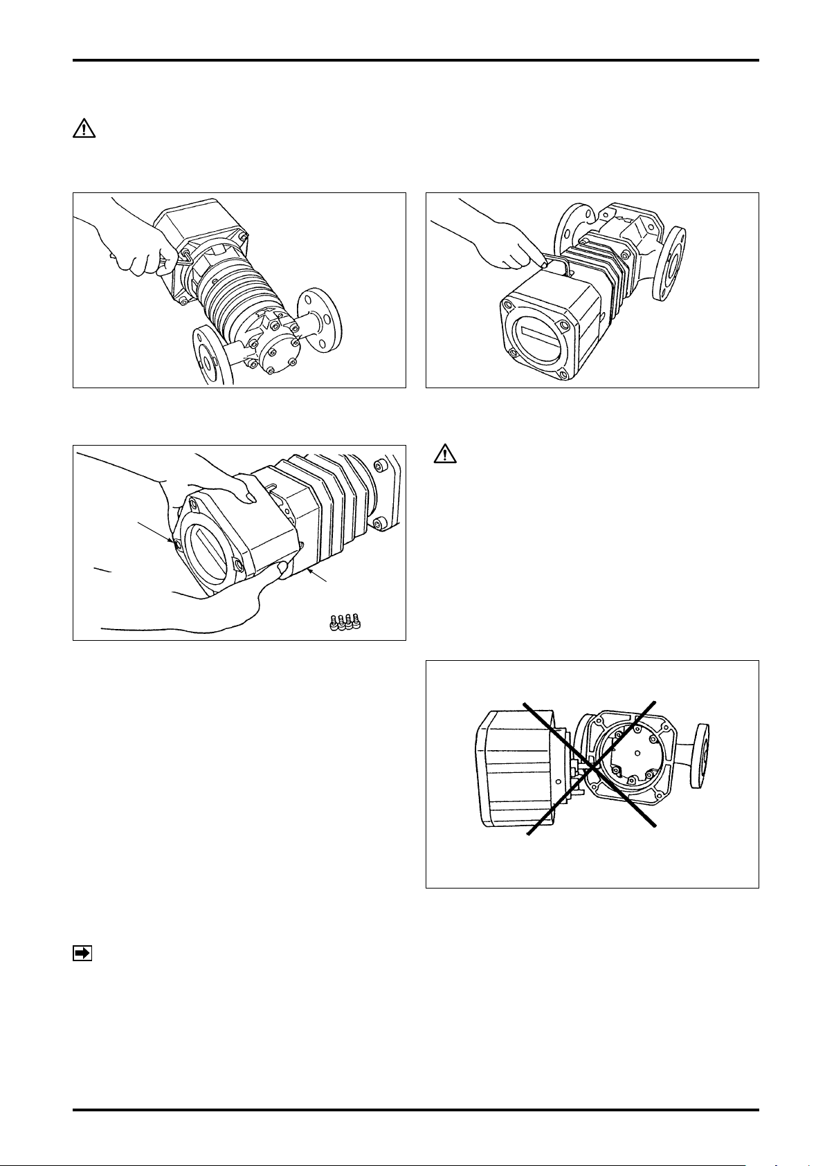
Size 50
Sizes 52, 53, 55, 56, 57
REGETER
ASSEMBLY
CAREFULLY
ROTATE.
SKIRT
Don’t separate!
7. HOW TO CHANGE FLOW DIRECTIONS
CAUTION: Do not fail to turn power OFF if the meter is of remote output type.
To reverse the ow direction, change the orientation of both the register and owmeter body to the new ow
direction.
(1) Take off four hex socket head screws (M6) with hex wrench.
(2) Holding the register assembly in both hands,
carefully rotate it and then secure it with hex
socket head screws in line with the new direction
of ow.
CAUTION
1. Rotate the register assembly without separating
it from the skirt.
2. Do not attempt to rotate the register assembly
more than one complete revolution.
Do not attempt to change ow directions by
separating the register assembly like this.
NOTE: If you have separated the register assembly, first return it to the state before changing the flow
direction, then follow the correct procedure in step (2) (without separating the register assembly)
again to change ow directions.
10
 Loading...