


Ins. No.
B-149-4N-E
High Temp./Low Temp. Service and Jacketed
SMART ULTRA OVAL FLOWMETERS
Meter Sizes 50, 52, 53, 55, 56, and 57
Meter size 50
Cooling tube provided
Meter sizes 52, 53, 55, 56
Meter size 57
Cooling tube provided
Every SMART ULTRA OVAL is fabricated and shipped from our factory under stringent quality control. In
order to maintain its design performance throughout the life of the meter, this manual offers the operator the
necessary installation, operation and maintenance information.
Be well familiar with these instructions before you place the meter in service and keep this manual at the eld
location for ready reference.
The standard, high temperature-service, low temperature-service, and jacketed type meters all have in
common the same specifications described in this instruction manual except for some differences in the
jacketed type on its piping procedure and operating precautions. Be careful to observe the instructions given
with a reminder "See also page 15 for the jacketed type".
About Meter Size Designation
◆
The size of OVAL positive-displacement owmeters is basically identied by a two-digit code. For complete
details, see Section 17 PRODUCT CODE EXPLANATION.
◆
Heating tube provided
1

B-149-4N-E
CONTENTS
1. BEFORE YOU BEGIN ........................................................................................................................4
1.1 Conrming the Tag .........................................................................................................................4
1.2 Transportation Considerations .......................................................................................................4
1.3 Storage Considerations .................................................................................................................4
1.4 Structural Considerations ..............................................................................................................5
2. OPERATING CONDITIONS ...............................................................................................................5
3. GENERAL DESCRIPTION .................................................................................................................6
4. PART NAMES .....................................................................................................................................6
5. LCD COUNTER DISPLAY ..................................................................................................................7
5.1 About "MODE" Switch ................................................................................................................... 7
5.2 Display Functions ........................................................................................................................... 7
5.3 Display Mode Selection .................................................................................................................7
5.4 Total Counter Reset ........................................................................................................................8
5.5 Considerations with Pulse Output Type ......................................................................................... 8
6. INSTALLATION ................................................................................................................................... 9
6.1 Considerations at Installation ......................................................................................................... 9
6.2 Standard Installation, Horizontal Line ............................................................................................9
6.3 Standard Installation, Vertical Line
6.4 Example of Faulty Piping ...............................................................................................................9
7. HOW TO CHANGE FLOW DIRECTIONS ........................................................................................10
8. WIRING INSTRUCTIONS ................................................................................................................11
8.1 Wiring Guidelines ........................................................................................................................11
8.2 Terminal Connections ...................................................................................................................11
8.3 Preamplier-to-Receiving Instrument Hookup ............................................................................. 12
9. OPERATING INSTRUCTIONS .........................................................................................................13
9.1 Operation .....................................................................................................................................13
9.2 Operating Precautions .................................................................................................................13
9.3 Precautions at Operation Shutdown ............................................................................................14
9.4 About Register Life ......................................................................................................................14
9.5 Piping Instructions and Operating Precautions of Jacketed Meters ...........................................15
10. DISASSEMBLY AND INSPECTION ...............................................................................................16
10.1 Size 50 Meter Body Disassembly and Inspection ......................................................................16
10.2 Size 50 Meter Body Assembly Procedure .................................................................................17
10.3 Sizes 52, 53, 55, 56, 57 Meter Body Disassembly and Inspection ............................................18
10.4 Sizes 52, 53, 55, 56, 57 Meter Body Assembly Procedure ........................................................19
........................................................................................................................................... 9
11. REGISTER SWITCH FUNCTIONS AND PARAMETER SETTING ................................................ 20
11.1 Switch Names and Functions ....................................................................................................20
11.2 Individual Test Pin Functions ......................................................................................................21
11.3 About Meter Factor .................................................................................................................... 21
2

B-149-4N-E
12. SENSOR REPLACEMENT PROCEDURE .....................................................................................22
13. TROUBLESHOOTING ....................................................................................................................23
14. EXPLODED VIEWS AND PARTS LIST .......................................................................................... 24
14.1 Meter Size 50 Exploded View and Parts List .............................................................................24
14.2 Meter Sizes 52 and 53 Exploded View and Parts List ...............................................................25
14.3 Meter Sizes 55 and 56 Exploded View and Parts List ...............................................................26
14.4 Meter Size 57 Exploded View and Parts List .............................................................................27
15. GENERAL SPECIFICATIONS ........................................................................................................28
16. OUTLINE DIMENSIONS ................................................................................................................29
17. PRODUCT CODE EXPLANATION .................................................................................................30
CONVENTIONS
Shown in this manual are the signal words NOTE, CAUTION and WARNING, as described in the
examples below:
NOTE: Notes are separated from the general text to bring the user's attention to
important information.
CAUTION: Caution statements signal the user about hazards or unsafe practices
which could result in minor personal injury or product or property damage.
WARNING: Warning statements signal the user about hazards or unsafe practices
which could result in severe personal injury or death.
3
B-149-4N-E
NAMEPLATE
(RATINGS SHOWN)
1. BEFORE YOU BEGIN
Every Smart Ultra OVAL is thoroughly tested before it leaves the factory. When received, it should be thoroughly
inspected for indication of rough handling during transit. Necessary handling precautions are described in this
section; read the instructions carefully.
As for other information, nd the respective sections from "CONTENTS" on pages 2.
For any inquiries, contact your nearest OVAL designated sales ofce.
CAUTION: When you make inquiries, include the product name, model number,
product number, ratings and other pertinent information.
1.1 Confirming the Tag
Every Smart Ultra OVAL is assembled and adjusted
ac cordi ng to indivi dual s pec ifications. Produ ct
code number and ratings are stated on the register
tag. Make sure that, by referring to the general
specifications on pages 28 and the product code
explanation on page 29, the ratings shown conform
to your particular specication.
1.2 Transportation Considerations
(1) To safeguard against damage during transit, transport your Smart Ultra OVAL to the installation site in the
same container used for transportation from the factory if circumstances permit.
(2) Smart Ultra OVAL is adjusted and inspected as an assembly consisting of the meter body, sensor and
register. It should therefore be handled as an integral assembly.
(3) The register is accurately congured and adjusted. Do not attempt to remove the front cover to gain access
to its internal assembly.
1.3 Storage Considerations
If your Smart Ultra OVAL is stored for long periods of time upon receipt before installation, unexpected faulty
conditions could result. If a long-term storage is anticipated, take the following precautions:
(1) Keep your Smart Ultra OVAL in store in the same shipping container used for transportation from OVAL if
possible.
(2) Place of storage should conform to the following requirements:
- Free from rain and water.
- Free from vibration and impact shocks.
- Temperature and relative humidity in the storage place are at or near room temperature and humidity
(3) Purge the Smart Ultra OVAL that has once been placed in service with clean air, N2 gas, etc. to prevent the
metered uid from adhering to the meter connections, piping inner walls, housing, etc. before storage. (Wash
clean with suitable detergent if necessary.)
(4) In case of storage for extended periods of time, good practice is to keep in store in the same containers
used for shipment from the factory.
(around 25°C and 65%).
4
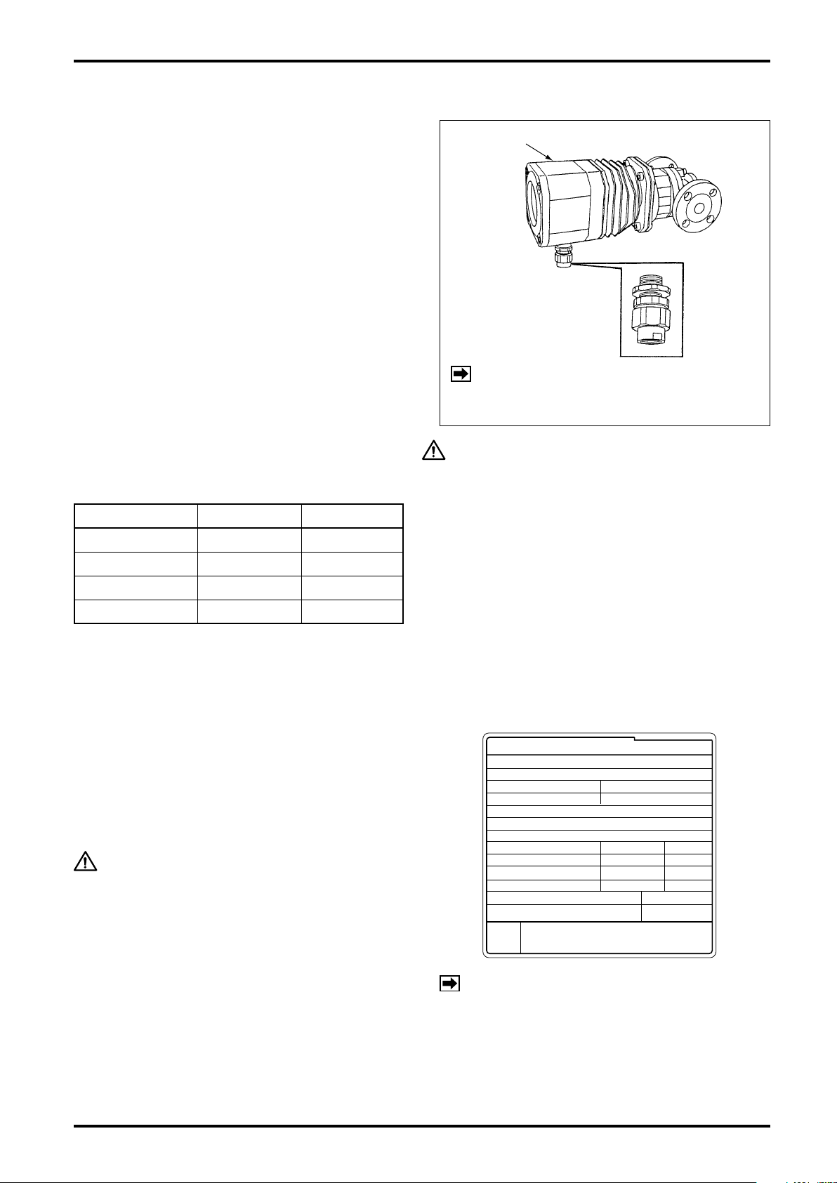
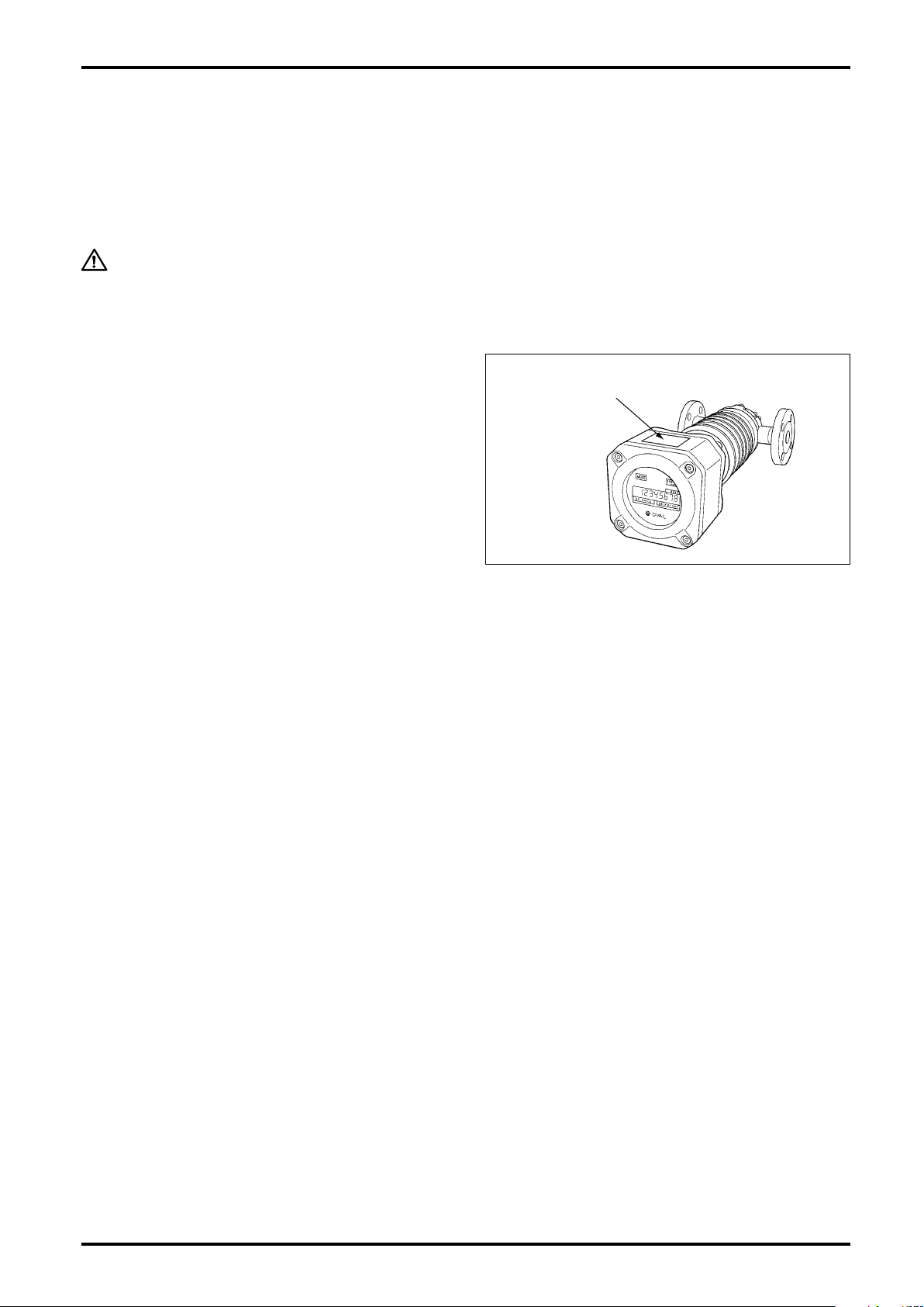
1.4 Structural Considerations
Register
Cable Lead-in
(Pressure-resistant
packing)
ULTRA OVAL
MADE IN JAPAN MNPJ-237
OVAL Corporation
MODEL
TAG. No
MAX PRESS.
FLOW RANGE
INT.
CONT.
~
~
FULL SCALE
TEMP.
PULSEUNIT
SERIAL No.
FLUID
DATE
SIZE
METER FACTOR
NOTES
1. When measuring other liquids, consult us.
2. Place the meter body (outer case) in a horizontal
position. For details, see instruction manual.
(1) The register is of waterproof construction for
outdoor service.
(2) The register is type approved. Do not attempt to
replace component parts with others or make
any circuit modication.
(3) The pressuretight packing furnished constitutes
pa rt of the fla mepro of construction . Do not
attempt to use any pressuretight packing other
than those furnished. The pressuretight packing
union s h o u l d be ti g h t e n e d s e c u r e l y up o n
completion of connections.
(4) Of the four different p re ssure tight packings
(φ9,
10, φ11 and φ12) furnished as standard
φ
accessories, a
in place.
Sele c t from t h e s e and insta l l the one that
best fits the finished outside diameter of your
particular cable.
Table 1.1 Applicable Cable Outside Dia. Unit in mm
Packing Code Packing I.D. Cable O.D.
9 9.0
10 10.0 9.1 to 10.0
11 11.0 10.1 to 11.0
12 12.0 11.1 to 12.0
11 packing is tentatively installed
φ
8.5 to 9.0
B-149-4N-E
NOTE:
CAUTION
Moisture allowed into the register wil cause
blurred display glass and functional trouble.
Pr e c au t i o n s o n cab l e l e a d - i n fit t i ng
(pressuretight packing), both explosionproof
and non-explosionproof models:
- Use a pressuretight packing that fits the finished
cable O.D.
- Tighten up properly to allow no clearance between
the pressuretight packing and the cable.
- If a pressuretight packing is not used, apply some
waterproof treatment to preclude any chance of
moisture getting into the equipment.
P r e s s u r e t i g h t p a c ki n gs a re n o t
supp l i ed with n onexplo s ionpro o f
models.
2. OPERATING CONDITIONS
To ma intain the sta ted hig h a ccuracy and lon g
servic e life o f SM ART ULTR A O VA L flowme ter,
make sure that owrate, pressure, temperature and
viscosity are within the ratings as stamped on the
meter register nameplate. Do not fail to confirm
these ratings before placing it in service.
CAUTION
1. Although allowable ambient temperature is
up to +60 °C for explosionproof units, it is
desirable that the meter be used at room
temperature and humidity.
2. In cases where the register is exposed to
elevated temperatures due to exposure to
direct rays of the sun or to radiant heat,
ensure, by providing a sunshade or similar
protection, that the meter is used within
the operating temperature range.
NOTE: Avoid such installation locations where
1. Not easy to access for servicing.
2. Large temperature variation and vibration.
3. Potential risk of submersion in water.
4. Corrosive gas atmosphere.
5. Not compatible with ex. construction.
6. Near sources of strong magnetic noises.
5
B-149-4N-E
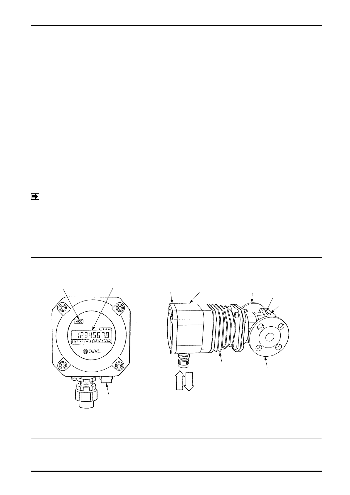
MODE SWITCH LCD COUNTER
FRONT COVER REGISTER
FLOW DIRECTION
REAR COVER
SELECTOR
MAGNET
CONNECTING
FLANGE
METER BODY
COOLING TUBE
(OR HEATING TUBE)
PRESSURETIGHT
PACKING
POWER
SIGNAL
3. GENERAL DESCRIPTION
Smart Ultra OVAL has been developed to meet the needs of precise owrate measurement. The local direct-
reading total counter is an all-electronic register built around a single-chip CPU. With the latest electronic
technologies used throughout, this versatile register displays accumulated total ow, instantaneous owrate
(digital readout) and provides, by option, a pulse and analog output proportional to the rate of ow.
In this meter, uid ow is detected by sensing with an amorphous sensor the magnetic elds of permanent
magnets embedded in the oval rotors. As a result, high reliability is achieved.
Features
(1) Absence of any mechanically sliding components except for oval rotors contributes to long service life.
(2) Small wetted parts count and pocketless design makes this meter ideally suited for ow measurement of
chemical liquids.
(3) You can monitor accumulated total ow and instantaneous owrate locally on the digital display.
(4) When coupled with a remotely located receiving instrument, output signals can readily and simply be used
for applications including control, adjustment and recording.
(5) IEC explosionproof construction offers increased safety and the design is compact.
(6) A nonvolatile memory, both in the local totalizer type and externally powered type meters, retains
accumulated total in the event of power failure or when de-energized.
NOTE:
If you have any request, contact the supplier you purchased the product or our sales ofce.
With the use over an extended period of time, meter error will deviate more or less from the initial
point. Upon request, we may conduct an instrumental error testing once again and establish a
"new meter factor" in the scaler when your Smart Ultra OVAL is returned to the factory for periodic
inspection or for other reasons.
4. PART NAMES
Fig. 4.1
6
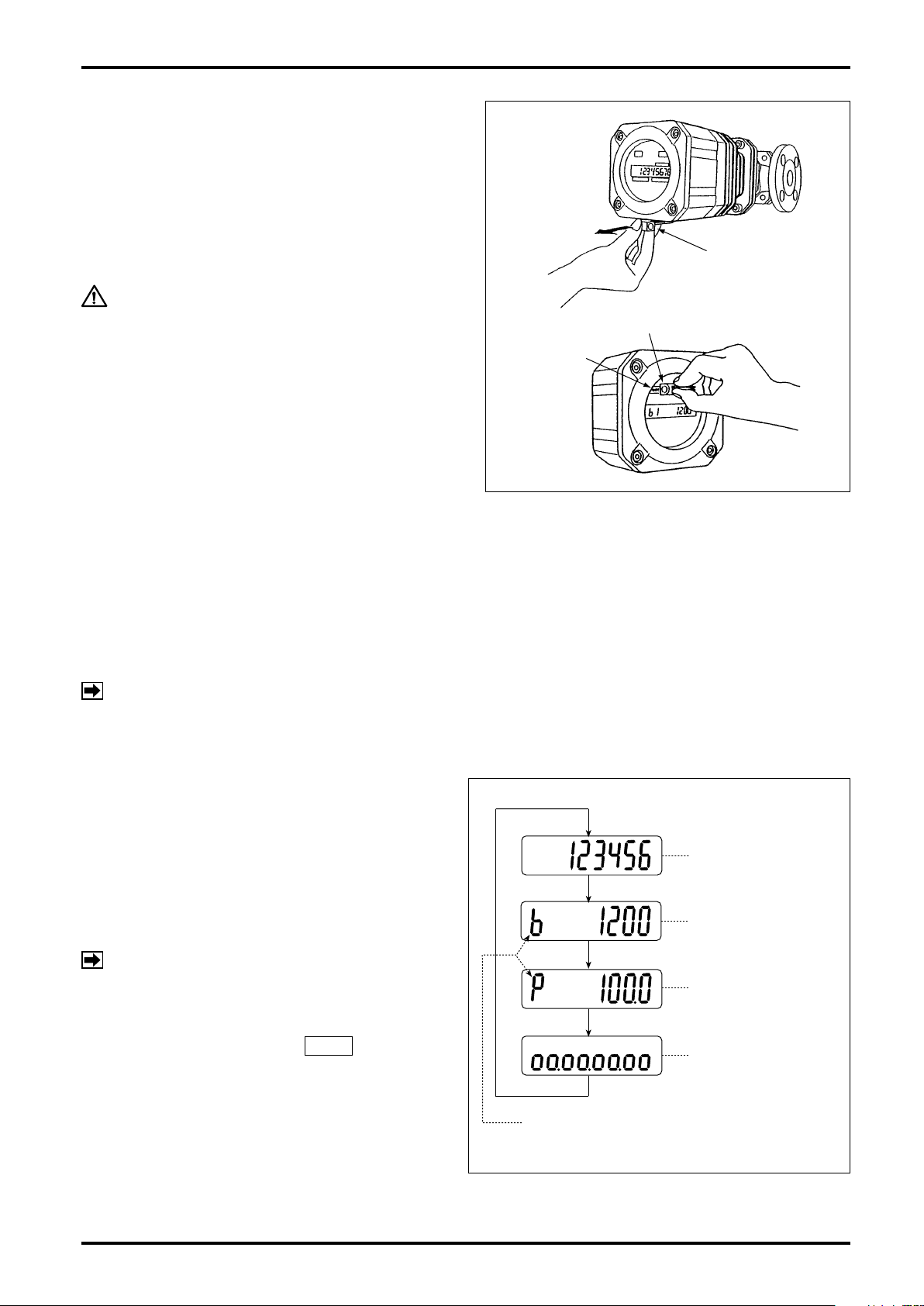
5. LCD COUNTER DISPLAY
SELECTOR MAGNET
SELECTOR MAGNET
"MODE"
EXAMPLE OF READINGS
MODE SYMBOL
TOTALIZED FLOW
INSTANTANEOUS
ACTUAL FLOWRATE
% INSTANTANEOUS
FLOWRATE
8-DIVISION
BAR GRAPH
5.1 About "MODE" Switch
Rem ovin g the sele ctor magn et ins erte d at the
bottom of the register, apply it to the label "MODE"
on the LCD counter face and the display will scroll
forward through the available readings as shown in
Fig. 5.1.
CAUTION
Do not fail to return the selector magnet
to its holder after use lest you will not
lose it. It uses an intensive magnet; never
hold it close to floppy disks or other
magnetic storage media.
B-149-4N-E
5.2 Display Functions
The display can show four different kinds of ow information - total ow, instantaneous actual owrate, percent
instantaneous owrate, and 8-division percent bar graph.
It also shows the following error messages:
Full scale exceeded : ErrorFS
Upper-limit owrate exceeded : ErrorOF
NOTE: Multiple errors will be indicated in priority order below:
ErrorOF > ErrorFS
5.3 Display Mode Selection
Two ways are available to select displays - with a
display select switch inside the register, or through
communications with the Smart Communication Unit
Model EL2310 (or HHC: Model EK10).
If your option is through communications, follow the
instructions outlined in the Smart Communication
Unit EL2310 (or HHC: EK10) instruction manual.
NOTE: Show "Measure" window at "View" menu
on the PC screen.
Selection with display select switch requires access
to the display sel ect switch SW1 by open ing
the register cover facing its internal assembly and
pressi ng this switch (see page 20) . T he display
scrolls forward through available information each
time you press this switch as shown in Fig. 5.1.
Fig. 5.1
7
B-149-4N-E
②
①
15 seconds after power on.
(Com Standby Mode)
Communication is started
within 15 seconds after
power on. (Com Mode)
5.4 Total Counter Reset
Displayed total flow can be reset either by the display select switch SW1 (see Fig. 11.1 on page 20) or
through communications with the Smart Communication Unit. It your option is through communications, follow
the instructions outlined in the Smart Communication Unit EL2310 (or HHC: EK10) instruction manual.
NOTE: Show "Measure" window at "View" menu on the PC screen.
With the display select switch, then, you can reset the totalizer by holding the display select switch SW1
depressed for more than 3 seconds while the total ow is shown.
5.5 Considerations with Pulse Output Type
(1) If your model is of pulse output type, the pulse output and total counter remain inoperative for 15 seconds
approx. after power on and while communications with the Smart Communication Unit continue. For 15 seconds
approx. after termination of communications, the pulse output and total counter also remain inoperative.
(2) Requirements for validating communications
Communications are made valid only when the following requirements are met:
- Flowrate at zero (There is no pulse output.)
- Within 15 seconds after power turn-on
NOTE:
If communications are started during this time period, a switchover to "Communication mode" takes
To start ow measurement routine, turn power on again. (After power cycling, the pulse output and
The period of 15 seconds immediately after power on is called "Communication standby mode." (The
built-in indicator, if so equipped, will display as shown in
place, permitting you to communicate until power is turned off the next time. (The built-in indicator
will display as shown in ② in the gure below.)
total counter will also remain inoperative for 15 seconds.)
in the gure below.)
①
(3) While communications continue, the receiving instrument (total counter, etc.) may overcount under certain
circumstances. To eliminate the possibility of such erratic extra counting, precautions should be taken by
either disconnecting the receiving instrument before starting communications, or recording the most recent
total reading and other important data on paper.
(4) Except for the purpose of communications, do not attempt to connect the probe of Smart Communication
Unit with the signal lines. If the probe remains connected, the influence of capacitive impedance the
interface has could go to the point of producing distorted signals in waveform and, as a result, the receiving
instrument would fail to receive pulse signals accurately.
The analog type permits communications with the Smart Communication Unit at any
time. However, if, in an attempt to alter current parameters, the meter is configured
by mistake such that the new parameters are incompatible with the specification,
re sultan t sharp change s in out put may d istur b the b ehavio r of the rece iving
instrument. It is good practice, therefore, to make parameter changes while the fluid
flow is at zero.
8
Fig. 5.2 Display in Response to Power ON, Pulse Output Type
CAUTION: PRECAUTIONS with ANALOG OUTPUT TYPE
6. INSTALLATION
BYPASS LINE
STRAINER
VALVE
SHORT PIPE
FLOW
DIRECTION
OUT
IN
A
B
BYPASS
STRAINER
ULTRA OVAL
OU
T
IN
*(1100mm)
WRONG!
OUT
IN
B-149-4N-E
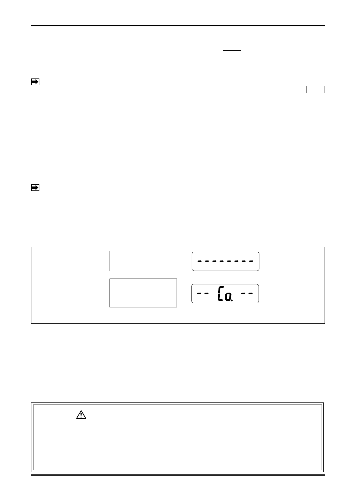
6.1 Considerations at Installation
"See also page 15 for the jacketed type".
(1) Flush the piping assembly.
Flushing must be performed before meter installation. Install a short pipe in place of the meter at this time (see
diagram below).
(2) Install the meter free from pipe strains.
(3) The meter must be installed on the discharge side of the pump.
(4) If the meter is to be used under tank head, give a head pressure greater than the losses with the piping
system, strainer, meter, etc.
NOTE: Pressure losses of the Smart Ultra OVAL and strainers are stated in the GENERAL SPECIFICATIONS.
(5) The meter installation is correct if the ow direction conforms to the arrow mark on the meter body.
(6) The strainer should be located upstream of, and as close to the meter as possible.
(7) Since the sensor in the Smart Ultra OVAL operates on the principle of sensing changes in magnetic ux
density, it must be isolated from the influence of any external magnetic flux. In order to minimize the
influence of external magnetic flux, select an installation location at least 5 meters away from existing
power equipment and conductors - potential sources of creating strong magnetic and electric elds, such
as motors and generators.
(8) In case electric heating is desired, consult the factory.
(9) In the heat retention work, aviod covering up the ns and heating tube with lagging material.
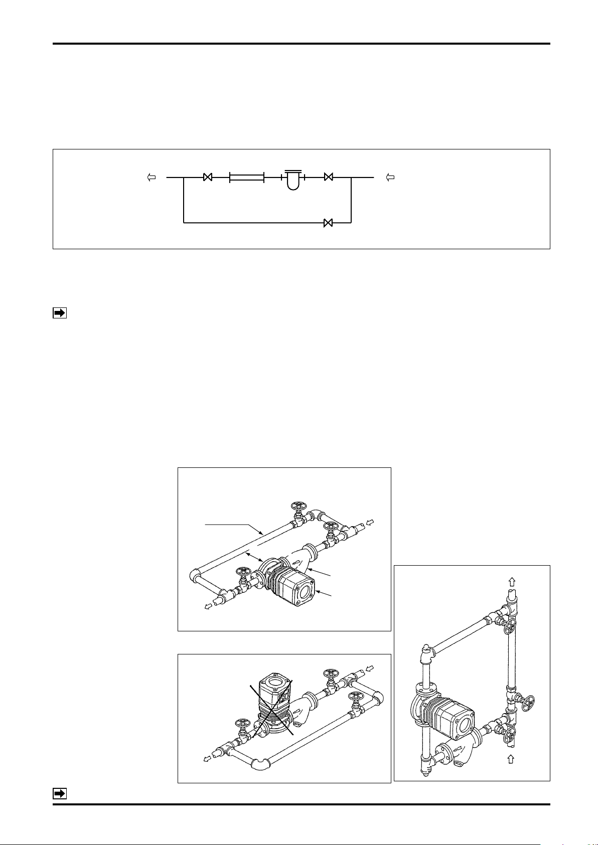
- Typical Smart Ultra OVAL Installations
6.2 Standard Installation, Horizontal Line
(1) In c a s e f l o w d i r e c t i o n
is fr o m R t o L , s w i t c h
the places of meter and
strainer.
(2) Arran ge piping so as to
facilitate drainage.
(3) S t r a i n e r s h o u l d b e
ins p ecte d on a regu l ar
basis.
6.4 Example of Faulty Piping
Do not install the meter in
a position like this.
Marked * is the space required for disassembly
and inspection.
6.3
Standard Installation, Vertical Line
(1) If the ow direction is from top to
bottom, switch the places of meter
and strainer.
(2) Installing the strainer at "A" will
make net reinstallation difficult at
cleaning; we recommend to install
the strainer at "B".
NOTE: For outline dimensions and pipe connection dimensions, see approval drawing.
9
B-149-4N-E
Size 50
Sizes 52, 53, 55, 56, 57
REGETER
ASSEMBLY
CAREFULLY
ROTATE.
SKIRT
Don’t separate!
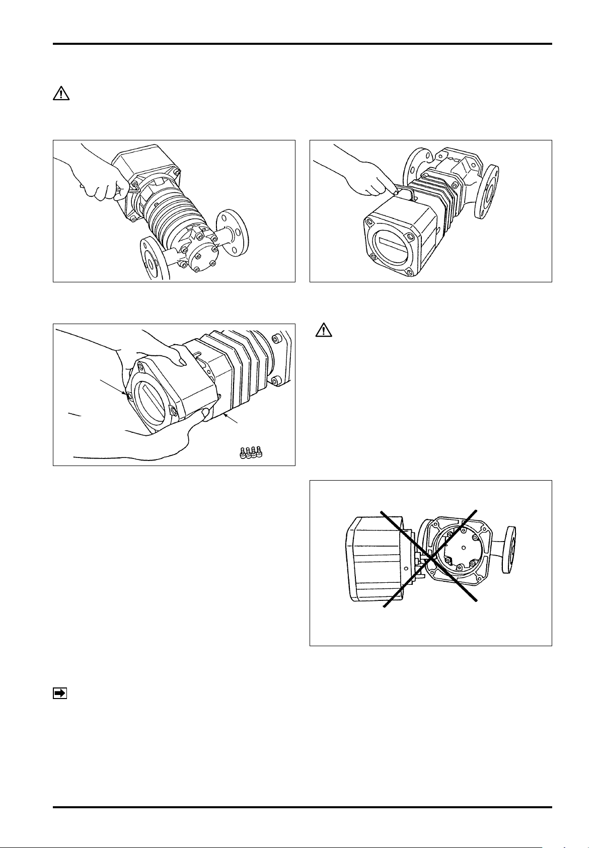
7. HOW TO CHANGE FLOW DIRECTIONS
CAUTION: Do not fail to turn power OFF if the meter is of remote output type.
To reverse the ow direction, change the orientation of both the register and owmeter body to the new ow
direction.
(1) Take off four hex socket head screws (M6) with hex wrench.
(2) Holding the register assembly in both hands,
carefully rotate it and then secure it with hex
socket head screws in line with the new direction
of ow.
CAUTION
1. Rotate the register assembly without separating
it from the skirt.
2. Do not attempt to rotate the register assembly
more than one complete revolution.
Do not attempt to change ow directions by
separating the register assembly like this.
NOTE: If you have separated the register assembly, first return it to the state before changing the flow
direction, then follow the correct procedure in step (2) (without separating the register assembly)
again to change ow directions.
10

B-149-4N-E
HEX
WRENCH
COVER
HEX SOCKET
HEAD BOLTS
O-RING
REMOTE OUTPUT
TERMINALS
EXTERNAL GROUND
TERMINAL
INTERNAL GROUND
TERMINAL
8. WIRING INSTRUCTIONS
(Refer also to the wiring instructions of respective receiving instrument
instruction manual.)
8.1 Wiring Guidelines
(1) Cables for field wiring
The following cables should be used unless otherwise specied:
Use cables of conductor area 1.25mm2 and nished O.D. 12mm, selecting from 2 to 4pcs. according to your
application. It is recommended that their shield be grounded at the receiving instrument.
CAUTION: In case of TIIS explosionproof type used under the ambient temperature of
50°C or higher, use a cable resistant to the temperature of 70°C or higher.
(2) Transmission length
The maximum transmission length is typically one kilometer.
NOTE: If it exceeds one kilometer, consult us.
(3) Inductive interference prevention
To minimize the possibility of stray current pickup, the eld wiring should be routed sufciently away from
existing power cables or power circuits.
(4) Considerations on connections
1) M3.5 terminal posts are used on the terminal block. Use crimp-style terminals that t the conductors at the
cable end.
2) Be sure to earth ground the preamplier's ground terminal.
3) Pitch down the cable from the cable entry so that rainwater will not have a chance to enter the equipment
through the cable.
4) In areas where lightning strokes are expected, provide a lightning arrestor for protection.
8.2 Terminal Connections
(1) Take off four hex socket head bolts (402) on the
(3) U s i ng crimp e d-lug t ermina l s , ensur e good
CAUTION: Make sure of the validity of meter (register) and receiving instrument
combination by referring to their model numbers, serial numbers, etc.
before you make electrical connections.
(2) Remove the cover to gain access to a 4-post
front of register assembly and remove the cover
(401).
electrical connections.
terminal block. Terminal identication is found on
the back of cover.
NOTE:
1. Pressuretight packing is not furnished with non-
explosionproof models and non-output models
(see page 5).
2. Connect the external earth ground terminal to
instrumentation earth ground before use.
11

B-149-4N-E
Supply Voltage (VDC)
Acceptable Load Resistance Range.
RL(Load Resist.)
0 12V
17.25V
45V
1000Ω
1571Ω
250Ω
33V
Area: Operating range
Area: Acceptable Communication range
R
=
L
E−12V
21mA
EXAMPLE:
If supply voltage is 24V DC with load
resistance 250Ω, then a 1 to 5V DC
output is obtained.
(
(
L
PC POWER
R
+
−
VOLT. SIGNAL
TO RECEIVING
INSTRUMENT
+
−
OPEN COLLECTOR
OUTPUT
30V, 50mA max.
FLOWMETER
REGISTER
GND
+
−
2
1
4
3
+
−
(SMART COMMUNICATION UNIT)
(OR HHC:EK10)
PC
(SMART COMMUNICATION UNIT)
(OR HHC:EK10)
PC
8.3 Preamplifier-to-Receiving Instrument Hookup
The 2-wire signal transmission system used in this owmeter furnishes DC power to the meter. It serves as the
power line and signal line as well with pulse or analog current output.
An OVAL receiving instrument can be coupled directly, but instruments in general which are designed to
accept a voltage signal input require a load resistor RL connected in series for voltage conversion. Since the
voltage signal level varies with the load resistance value, determine the load resistance value by referring to the
receiving instrument specications and the acceptable load resistance range shown below.
Communications with a PC (Smart Communication Unit) requires a 250 to 1000Ω load.
In case a voltage input is fed to the receiving instrument
●
R
L
Output Voltage Signal (V)
Pulse
Output
Analog
Output
(20mA × RL) / (4mA × RL)
(4mA × RL) − (20mA × RL)
ON/OFF =
at 0 ro FS
NOTE: With the relationship with supply
voltage E, select the load resistance
value RL such th a t t he c u r r e n t
flowing into the transistor is held
below 50mA.
Fig. 8.1
12
Fig. 8.2

9. OPERATING INSTRUCTIONS
A
B
C
BYPASS LINE
METER
STRAINER
VALVE
FLOW DIRECTION
EXCESSIVE
FLOW
RAPID FLOW
VARIATION
RAPID TEMPERATURE
CHANGES
B-149-4N-E
9.1 Operation
At rst-time operation, carefully operate in the following sequence, allowing the ow within the ow range
specied. (Refer to the piping diagram below.)
(1) Shut off the valve (A) on the inlet side and the valve (B) on the outlet side and then open the bypass line
valve (C) to allow the uid in the bypass line, thereby removing weld chips, scales and other foreign matter
left in the piping assembly.
"See also page 15 for the jacketed type".
CAUTION: This is particularly important on new installations.
(2) Carefully and slightly at rst, open the valve (A) upstream of the meter progressively and then, slightly at
rst, open the valve (B) downstream progressively.
(3) Slowly close the bypass line valve (C) and make sure that the total counter in the register advances in
response. Maintain a owrate 10 to 20% of the maximum owrate (conrm it in the instantaneous owrate
display mode) at this time, allow the ow for more than 15 minutes and make sure that air in the piping
assembly has totally escaped.
In applications where temperature exceeds 60°C, run the system at least for 30 minutes in this state to
ensure uniform heat distribution in the measuring chamber.
(4) Following the break-in operation (preheating), shut off the bypass line valve (C) completely and open the
upstream valve (A) progressively until fully open and slowly open the downstream valve (B) until the rated
ow is obtained.
(5) Flowrate should be regulated with the valve (B) downstream of the meter and should be held within the
rating.
(6) The strainer net should be inspected for condition and cleaned on a regular basis. On a new installation, in
particular, inspect daily rst and, according to the clogged condition of the net being observed, inspection
intervals may be reduced progressively to, say, once a week.
9.2 Operating Precautions
(1) When changing flowrates
In applications where the flowrate varies or where
shutoff valve opening and closure takes place in
batch operation, avoid rapid changes in flowrate
across the meter.
Ope r ating the m e ter a t flow r ates i n exce ss of
th e maximum allowable fl owrate wi ll nul lify the
guaranteed accuracy, reduce the meter life and may
result in faulty conditions, such as the seizure of
bearings or the rotor-to-measuring chamber contact.
(2) Whe re the t e mpera t u re o f metere d fluid
changes
Avoid rapid tem per atu re changes i n th e me ter.
Temperature changes of the uid in the meter should
be held within 3°C per minute.
Extra care should be used particularly when making
a ow measurement in batch operation without the
provision of heat tracing of the piping where the uid
temperature differs from atmospheric temperature.
If rapid temperature changes are anticipated, heat
trace the piping assembly as well as the meter.
13

B-149-4N-E
TAKE PRECAUTIONS
AGAINST BEARING SEIZURE!
(3) Liquids of low steam pressure
Temperature and pressure of LPG, polyvinyl chloride
monomers or anything with low viscosity and low
steam pressure that are too ready to vaporize should
strictly be controlled.
During operation, the temperature of bearings in the
meter is usually higher than that of the metered uid.
Vapors around the bearings can be causes of faulty
conditions, including generation of unusual noise
and bearing seizure.
(4) Corrosive liquids
When you make a measurement of highly corrosive
liqui d s , such as nitric a c i d a n d sulfuric a c i d,
appropriate materials should be used for tanks
an d p iping assem bly. He terogeneous m aterials
originally contained in the metered uid or corrosive
substances liquated out from tanks and pipes of
inappropriate materials may lead to costly downtime,
as a result of locked rotors, for example, when they
are allowed into the measuring chamber.
CAUTION: If it is a jacketed model, see page 15.
9.3 Precautions at Operation Shutdown
(1) Valves should be closed progressively.
Rapid valve closure could, under certain piping conditions, cause a sharp pressure rise by water hammer, or
hydraulic shock, resulting in damage to the meter.
(2) Precautions against pressure buildup on closure
Complete closure of valves upstream and downstream of the meter makes the affected section a totally
enclosed chamber and could cause a rise of internal pressure due to a rise of atmospheric temperature,
resulting in an unexpected damage to the meter.
(3) Liquids ready to adhere or gel at zero flow velocity
Liquids that tend to adhere and solidify or gel at ow velocities around zero must thoroughly be washed away
from the meter interior by running cleaning uid before shutdown. Negligence of this instruction may leave the
meter as an immovable unit when the operator attempts to resume meter operation the next time.
CAUTION
9.4 About Register Life
Due to the life expectancy of components incorporated, such as the LCD and nonvolatile memory, the internal
electronics are designed to be replaced in about 10 years. The electronics life depends on the environment in
which they are used; if any of the following operating conditions applies, we recommend you to replace them
an assembly in ve to six years:
- High temperature environment.
- High temperature process uid measurement.
- Field installation with widely varying temperatures.
- LCD counter display is directly exposed to the rays of the sun (ultraviolet rays).
- Frequent process uid ow interruptions.
14

B-149-4N-E
STEAM IN
OUT
FLOW
DIRECTION
IN
OUT
FLOW
DIRECTION
HOT WATER
CAUTION
9.5 Piping Instructions and Operating Precautions of Jacketed Meters
Hot water or steam jacketed meters require piping work in the following manner:
(1) Piping to the meter body remains the same as that of standard meters (meters not jacketed).
(2) Adhere to the following instructions for the piping to the jacket:
Steam Jacketed
Basically, the piping should be so arranged that
steam ows in from the top and out from the bottom.
Provi de stea m traps at outl et port s (s ee figu re
below).
⇩
Steam Jacketed Type, Horizontal Run
Hot-water Jacketed
Basically, the piping should be so arranged that hot
water ows in from the top and out from the top (see
gure below).
Hot Water Jacketed Type, Horizontal Run
⇩
(3) Although the measuring chamber is heat treated, due consideration should be taken not to give piping
elongation or contraction by sharp temperature changes or pipe strains.
Progressive heating is suggested at least four hours before commencing service operation.
(4) As for outline dimensions and tubing connection dimensions, see approval drawings.
(5) If heat tracing is desired, considerations should be taken to facilitate maintenance and servicing.
Make sure, if it is the case, that there is no liquid leaks when related components are covered with lagging
material.
(6) Lagging should be so provided that the top cover of strainer is easily accessible. Also it is necessary that
the strainer net be cleaned on a regular basis.
(7) Never attempt to lag radiator ns.
Lagging them will cause excessive heat buildup in the register and pulse generator, possibly leading to
costly downtime.
NOTE: As for outline dimensions and tube connection dimensions, see approval
drawing.
15

B-149-4N-E
METER BODY
HEX SOCKET
HEAD BOLTS
FRONT COVER
O-RING
HEX SOCKET
HEAD BOLTS
ROTOR SHAFTS
ROTORS
MEASURING
CHAMBER
10. DISASSEMBLY AND INSPECTION
Although it depends on individual operating conditions, periodic disassembly and inspection should be
performed at least once a year.
CAUTION: Because Smart Ultra OVAL is a prec ision indus trial instr ument,
disassembly and inspection should be performed indoors as a rule. If it is
desired to disassemble and inspect it as installed in the field, an important
precaution to remember is to reduce the internal pressure of the piping
assembly to a safe level, shut off valves upstream and downstream of
the meter fully, drain the piping assembly and then place a suitable fluid
receptacle directly below the Smart Ultra OVAL. Exercise care to keep
individual components disassembled free from grit and dust.
CAUTION: Be sure to deenergize before you disassemble.
Meter Body Inspection
◆
Complaint and possible cause: Process fluid will not run. Jammed with scales, the oval rotors fail
to rotate, resulting in an interrupted fluid flow.
10.1 Size 50 Meter Body Disassembly and Inspection
◆
(1) Take off all six front cover tting bolts (104) (M6),
using wrench.
With the bolts removed, the register integral with
the front cover is ready to be separated from the
meter body.
Be careful not to drop the register front cover
assembly.
(3) Remove oval rotors (201) from the measuring
chamber and inspect them for condition.
(a) Inspect the oval rotors to see if they are jammed
with foreign solids.
(b) Check the rotors, shafts and other members for
wear.
16
(2) Wi th the front cover (regi ster) remov ed, the
measuring chamber with oval rotors and other
components are now accessible.
(c) Inspect the measuring chamber and the inner
wall of front cover for damage or any other sign
of unusual condition.
Upon completion of these inspections, clean the
oval rotors, rotor shafts, measuring chamber and
front cover with clean water or suitable solvent
thoroughly.
CAUTION
1. Score marks, scratches, high spots due
to impressions, or other flaws should
be reconditioned flat with oil stone or
other tool.
2. If the areas which have been in contact
with rear cover jack bolts are distorted
outwardly, recondition it flat with oil
stone.

B-149-4N-E
MATCH MARKS
1ST ROTOR SIG.
MAGNETS
IN
1
2
OUT
2ND ROTOR
FLOW DIR. ARROW AND
2ND ROTOR NO.
FLOW DIRECTION
FLOW DIR. ARROW AND
1ST ROTOR NO.
IN
OUT
FRONT COVER
O-RING
HEX BOLTS
(REGISTER SIDE)
10.2 Size 50 Meter Body Assembly Procedure
CAUTION: PRECAUTIONS BEFORE ASSEMBLY
Oval rotors, inner walls of the rotor shafts, inner wall of the measuring chamber, inlet and outlet ports should be
thoroughly washed clean, completely removing dust, grime and other foreign matter.
Hot Water Jacketed Type, Horizontal Run
(1) Rotor Installation
Rotor installation is correct if the side where signal
generating magnets are embedded faces the register
(top in the measuring chamber) and the side with match
marks ( • ) ( • • ) faces the front cover.
Carefully install the rotors with the 1st rotor (match mark
" • ") on the shaft with "1" stamped on the outside of
measuring chamber and the 2nd rotor (match mark
" • • ") on the shaft with "2" stamped. Ensure that the
match marks are as shown in the inset.
(3) Front Cover Installation
Firstly install O-ring (108) on the front cover. If the
O-ring is damaged or swollen with metered liquid, it
will not t in the groove. If such is the case, replace
with a new one.
Align the locating pin of front cover with its pin slot
in the meter body and, fitting the rotor shafts into
rotor shaft sockets in the front cover, force the meter
body until the locating pin ts rmly in the pin slot
in the meter body without slanting the front cover.
Install six front cover fitting bolts (M6) and tighten
them evenly until the front cover is closely in contact
with the meter body.
(2) Confirming the Rotor Gear Engagement
Hand rotate the rotors to make sure of correct gear
mask.
(4) Confirming Freely Rotation
With air or water, make sure to see that the rotors
move freely and that the register counts in response.
CAUTION
Rotation check should be performed at
low rotor r.p.m.
Violent roto r s p inning m a y cause a
damage to the components, such as
bearing seizure.
CAUTION: Since the registers are not compatible each other, do not replace one
register with that of other meter.
17

B-149-4N-E
REAR
COVER
REAR COVER
HEX BOLTS
TOP COVER
REAR
COVER
GASKET
END PLATE
ROTOR SHAFT
REAR
COVER
TOP COVER
GASKET
ROTORS
10.3 Sizes 52, 53, 55, 56, 57 Meter Body Disassembly and Inspection
CAUTION: Be sure to deenergize before you disassemble.
(1) Take off all rear cover tting bolts, using wrench.
(3) Using cross slot screwdriver, remove all four
bolts securing the top cover in place. Then, use
two of them to jack up the top cover, eventually
to remove it.
CAUTION
When jacking the top cover off, turn the
jacking screws evenly and alternately so
that the top cover not slant.
(2) Remove the rear cover to gain access to the top
cover.
(4) W ith the top cov er rem oved, t he measuring
chamber with oval rotors and other components
are now accessible.
1. Score marks, scratches, high spots due to impressions, or other flaws should be
2. If the areas which have been in contact with rear cover forcing bolts are distorted
18
CAUTION
reconditioned flat with oil stone or other tool.
outwardly, recondition it flat with oil stone.
(5) Remove oval rotors and rotor shafts, in this order,
from the measuring chamber and inspect them
for condition. (The rotor shafts should be drawn
out straight.)
(a) Make sure to see if the o val rotors are
jammed with foreign matter.
(b) Check to see if the rotors, shafts and other
components are worn.
(c) Inspect if the measuring chamber and inner
wal l of the fron t cover have any sig n of
scratches or other damage.
Upon completion of these inspections, clean
the oval roto rs, rotor shaft s, mea s urin g
chamber and front cover with cleans water or
suitable solvent thoroughly.

B-149-4N-E
NON TURN
PIN
ROTOR
SHAFTS
SHAFT
SOCKET
ROTORS
2ND ROTOR "2" MARKS
1ST ROTOR "1" MARKS
FLOW
IN
OUT
MATCH MARKS
ROTORS
TOP COVER
REAR COVER
GASKET
10.4 Sizes 52, 53, 55, 56, 57 Meter Body Assembly Procedure
CAUTION: PRECAUTIONS BEFORE ASSEMBLY
Oval rotors, inner walls of the rotor shafts, inner wall of the measuring chamber, inlet and
outlet ports should be thoroughly washed clean, completely removing dust, grime and other
foreign matter.
(1) Rotor Shaft Installation
The non-turn pin end of each rotor shaft faces the
register (bottom of the measuring chamber). Install
the shafts, pin end first, into their sockets on the
bottom of measuring chamber (bottom of meter
body), forcing downward while turning each of them
with hands until they are rmly installed in position.
(Air in the sockets may resist to be compressed by
the shafts. So good practice is to hold the shafts
pressed down by hand for some time.)
(2) Rotor Installation
Rotor installation is correct if the side where signal
gener a t i ng magnets a re embedd e d faces the
register (bottom of the measuring chamber) and the
sides with match marks ( • ) ( • • ) faces the rear
cover. Carefully install the rotors with the 1st rotor
(match mark " • ") on the shaft with "1" stamped on
the outside of measuring chamber and the 2nd rotor
(match mark " • •" ) on the shaft with "2" stamped.
Ensure that the match marks are in alignment as
shown in the inset.
(3) Confirming the Rotor Gear Engagement
Hand rotate the rotors to make sure of correct gear
mesh. At this point, they may be shaky more or less
as the shafts not fixed firmly. Exercise care not to
damage the rotors and inner wall of the measuring
chamber by forcing them to rotate.
(5) Rear Cover Installation
Firstly install the gasket on the rear cover. If the
gasket is found damaged, replace it with a new one.
In stall rear cover fit tin g b olts a nd tig hten t hem
evenly.
(4) Installing top cover and confirming smooth rotor rotation
With the locating pin of top cover in line with its pin
slot in the meter body and tting the rotor shafts into
their sockets in the top cover, force them against the
meter body until the locating pin ts in its slot in the
meter body without slanting the top cover.
Install top cover fitting bolts and tighten each of
them evenly until the top cover is rmly in contact
with the meter body.
At this point, allowing air or water, make sure to
see that the rotors move freely and that the register
counts in response.
CAUTION
NOTE: We suggest to replace the gasket with a
new one at each disassembly.
Rotation check should be performed at low rotor
r.p.m. Violent rotor spinning may cause a damage
to meter components, such as bearing seizure.
CAUTION: Since the registers are not compatible each other, do not replace one
register with that of other meter.
19

B-149-4N-E
O-RING
FRONT
COVER
HEX SOCKET
HEAD BOLTS
TP-PIN
OUT 2 PIN
OUT 1 PIN
REV PINFWD PIN
MODE SELECT
SWITCH SW1
0V PICKUP POINT
EXTERNAL GND
TERMINAL
EXT. OUTPUT
TERMINAL
SELECTOR MAGNET
HOLDER
INTERNAL GND
TERMINAL
PARAMETER REWRITE
PROTECT SWITCH
(“ON” TO INHIBIT REWRITE)
IN PIN PLS PIN
11. REGISTER SWITCH FUNCTIONS AND PARAMETER SETTING
11.1 Switch Names and Functions
(1) Using a hex key, take off four hex socket head
bolts securing the front cover.
(2) Removing the front cover provides access to the
electronics unit.
20
Fig. 11.1 Part Names of Electronics Unit

11.2 Individual Test Pin Functions
10μs
200mV
200mV
1 to 1.5ms
3V
2ms
Depends on
"Pulse widt"setting.
20ms
T
NOTE: Connect the 0V end to the L.H. side fixed screw of the electronics unit.
PIN NAME FUNCTION WAVEFORM
An output of No. 1 amorphous sensor waveform
FWD
REV
PLS
IN
appears.
An output of No. 2 amorphous sensor waveform
appears. While the owmeter is making forward
revolutions, pulses are produced slightly behind the
FWD pulses.
A re c t a n gu l ar w a v e fo r m a f t e r F W D p u l s e
waveshaping appears. Timing remains the same
as tha t of FWD and its wav efor m is one bef ore
unfactored output amplication.
Accepts a square-wave pulse train from the pulse
checker (OVAL Model PC2201, for example).
Used for analog full scale adjustment, loop check, or
other servicing. Input mode is Model PC2201's PG30
mode. Also accepts pulses with levels "0": 1V max.
and "1": 7 to 12V min., or open collector.
Same as above.
B-149-4N-E
Provides a waveform corresponding to the power
(1) Unfactored pulse
signal which appears across remote output signal
terminals 1 and 2.
(2) Factored pulse
OUT1
(3) Analog output
T
2 to 10ms
≒
at 0 to FS
Produces a waveform corresponding to the open
OUT2
collector output which appears across remote output
terminals 3 and 4.
11.3 About Meter Factor
If it is desired to change meter factors in an instrumental error testing, for example, you may establish a new
meter factor by the following procedure.
Instrumental error testing must be conducted with proper facilities and procedures specied in the Weights and
Measures Law, Japanese Industrial Instruments Federation, JIS standards, or other established standards.
- How to Determine a New Meter Factor
New Meter Factor = (Current meter factor) × (1−
where current meter factor : Stated in the test report or on the tag of the product.
E : Instrumental error determined by the test (% )
CAUTION: The new meter factor should be put on paper for later reference.
E
100
) (mL/P)
21

B-149-4N-E
ELECTRONICS
UNIT
ELECTRONICS
UNIT
REGISTER
ASSEMBLY
SKIRT
HEX SOCKET
HEAD BOLTS
REGISTER
ASSEMBLY
SENSOR RETAINER
FITTING SCREW
ELECTRONICS
UNIT
CONNECTOR
CONNECTOR
C-SHAPED
STOP RING
SENSOR
FITTING DISC
SENSOR UNIT
153
152158
FLOW DIRECTION
ARROW
SENSOR
FITTING DISC
SENSOR
OPENING
BLIND PLUG
(153)
12. SENSOR REPLACEMENT PROCEDURE
NOTE: Size 55 meter body is shown here.
The same procedure applies to other size
models.
(1) Take off four hex socket head screws on the register.
(3) Take off four hex socket head bolts and separate the
cover.
(5) Holding the electronics unit in both hands, carefully draw
it out.
CAUTION: Use extra care not to damage the leads
by forcibly pulling the sensor fitting disc.
(2) Carefully draw the register assembly out. Exercising care
not to bump the sensor against adjacent components,
draw it out in the horizontal direction.
(4) With screwdriver, take off two tting screws holding the
electronics unit
(6) Uncouple the connector from the sensor unit at back of
the electronics unit.
(7) Using C-shaped stop ring pliers, remove the C-shaped
(9) Install a new sensor unit through the opening through
22
stop ring for the shaft. The sensor unit is now separable
from the register housing.
which the old sensor unit was removed and assemble in
the reverse order of disassembly.
(8) Loosen the sensor retainer fitting screws (M 4) with
screwdriver, remove the sensor retainer and draw out the
sensor unit.
LOCATION OF SENSOR INSTALLATION OPENING
(10) At register installation in the meter body, match the ow
direction of the meter body with the arrow on the sensor
tting disc.

13. TROUBLESHOOTING
PROBLEM PROBABLE CAUSE COPING ACTION
B-149-4N-E
1. Totalizer remains
inoperative.
2. Unusual noise.
3. Liquid leaks. 1. Incomplete seal of the pipeline. 1. Retighten bolts at pipeline connections or replace
4. Counts while valves
remain closed.
5. Analog output
unusual.
6. Accumulated total
too high.
7. Accumulated 1. Inuenced by external magnetic
1. Flowrate is low. 1. Open valves progressively.
2. Insufcient pump pressure or head
pressure.
3. Power line voltage is out of
specication or current carrying
capacity of power source is
inadequate.
4. Oval rotors jammed with foreign
matter; rotors locked; metered liquid
fails to run.
5. Oval rotors installed the wrong way. 5. Refer to 10.2 Meter Assembly
6. Sensor installed out of position. 6. Refer to "How to Change Flow
1. Air is entrapped.
2. Vaporized metered liquid in the
piping assembly.
3. Oval rotors revolving in contact with
measuring chamber.
2. Incomplete seal on front/rear cover
of meter body
1. Valve and pipeline leaks. 1. Inspect valves and pipeline.
2. Air pockets between valve and
Ultra OVAL; rotors in rocking motion
in response to pump's pulsating
pressure.
3. Supply power voltage uctuates. 3. Eliminate voltage uctuation.
1. Load resistance too great. 1. Referring to "Load Resistance
1. Rotors in rocking motion in response
to a pulsating ow.
2. Inuenced by external magnetic
elds (Meter sensor picks up external
magnetic elds created by a motor,
generator, etc.)
3. Air entrapped. 3. Provide an air vent.
elds.
2. T aking pressure loss of entire piping assembly into
consideration, correct pump pressure or head
pressure.
3. Provide a 14 to 45VDC power to the register. (12 to
24VDC for open collector or voltage pulse output.)
Current carrying capacity 30mA min. is required for
power. (With analog output, 24VDC, 60mA min. is
required.)
4. Referring to "Disassembly and Inspection" (Sec. 10),
disassemble the meter body and clean the rotors
thoroughly.
Procedure in the "Disassembly and Inspection", and
reassemble correctly.
Directions" (Sec. 7) and reinstall the sensor.
1. Reduce owrate and eliminate air completely in the
piping assembly.
2. Reduce owrate and control metered uid
temperature and pressure to prevent vaporization.
3. Refer to "Disassembly and Inspection" (Sec. 10), and
disassemble and inspect for condition.
gaskets with new ones.
2. Inspect front/rear cover tting bolts for tightness and
replace O-rings with new ones.
2. Vent air.
Provide a check valve and accumulator.
Range" on page 12, check load resistance to power
supply voltage relationship and keep them within the
specied range.
1. Add a check valve and accumulator.
2. Keep out external magnetic elds.
1. Keep out external magnetic elds.
23

B-149-4N-E
404
500
158
160
153
152
154
156
155
151
204
201
202
204 203
101
104
109
103
106
400
300
113
111
112
114
115
120
107
121
121
123A
123B
110
108
FLOW
14. EXPLODED VIEWS AND PARTS LIST
14.1 Meter Size 50 Exploded View and Parts List
- When you order replacement parts, specify the stock No., flowmeter model, instruction manual No.,
symbol No., part name and the quantity desired.
EXPLODED VIEW
PARTS LIST, Meter Size 50
Symbol
No.
101
103
104
106
107 O-Ring 1
▲
108
▲
109 O-Ring 1
▲
110
111 Skirt 1
112
113
114
115
120
121
151
152
153
: Recommended spare parts.
▲
: Rotors 201, 202 and rotor bearings 204 are available as an assembly.
※
24
Part Name Q'ty Remarks
Meter Body 1
Rear Cover 1
Front Cover Fitting Bolt 6 M8×35
Rear Cover Fitting Bolt 4 M6×15
G60
O-Ring 1
Front Cover Locating Pin
Skirt Locating Pin 2
Skirt Fitting Bolt 4 M8×20
Register Fitting Bolt 4 M6×15
Gasket 1
Sealing Flange 1
Iron Slug 1
Sensor Fitting Disc 1
Sensor Retainer 1
Blind Plug 1
G65
G40
2
Symbol
No.
154
155
156
158
160 Sensor 1
201 1st Rotor 1 w/Signal magnet
※
202
※
203
※
300
400
401
402
404
405
500
123 A
123 B Cooling Tube 1 set
204
Part Name Q'ty Remarks
O-Ring B 2 S10
O-Ring C 1 G65
C-shaped Stop Ring 1
Cross Recess Pan Head Screw
2nd Rotor 1 w/Signal magnet
Rotor Shaft 2
Rotor Bearing 4
Sensor Assembly 1 set (151 to 158, 160)
Register Assembly 1 set
Register Cover 1
Cover Fitting Bolt 4 M6 (w/washer)
Selector Magnet 1
Internal Assembly 1 set
Pressuretight Packing 1 set
Heating Tube 1 set
2
M4 X 8 (w/washer)
(w/screen, fr. cover)
(w/screen, fr. cover)

B-149-4N-E
404
500
158
160
153
154
156
155
151
203
204
204
211
201
213
107
104
102
400
300
108
103
114
113
101109
111
112
113
108
108
700B
700A
14.2 Meter Sizes 52 and 53 Exploded View and Parts List
- When you order replacement parts, specify the stock No., flowmeter model, instruction manual No.,
symbol No., part name and the quantity desired.
EXPLODED VIEW
4 PARTS LIST, Meter Sizes 52 and 53
Sym. No. Part Name
101
102
103
104
▲
107
108
109
Meter Body 1 1
Rear Cover 1 1
Skirt 1 1
Gasket 1 1
Rear Cover Fitting Bolt 4 M12×30 4 M12×30
Skirt Fitting Bolt 8 M10×20 8 M10×20
Gasket 1 t=1.5 1 t=1.5
Q'ty Remarks Q'ty Remarks
111 Meter Body Skirt 1 1
112
113
114
151
152
153
154
155
156
158
160
※201 First and Second Rotor
203
※204 Rotor Bearing 4 4
211
213
300
400
401
402
404
405
500
700A
700B
: Recommended spare parts.
▲
: Rotors 201 and rotor bearings 204 are available as an assembly.
※
Fitting Bolt 4 M8×12 4 M8×12
Gasket 2 t=1.5 2 t=1.5
Register Fitting Hex Socket Head Screw
Sensor Fitting Disc 1 1
4 M6×15 4 M6×15
Sensor Retainer 1 1
Blind Plug 1 1
O-Ring B 2 S10 2 S10
O-Ring C 1 G65 1 G65
C-shaped Stop Ring 1 1
Cross Recess Pan Head Screw
2 M4×8 (w/washer) 2 M4×8 (w/washer)
Sensor 1 1
1 each
Rotor Shaft 2 2
Top Cover 1 1
Top Cover Fitting Bolt 4 M6×12 4 M6×12
Sensor Assembly 1 set (151 to 158, 160) 1 set (151 to 158, 160)
Register Assembly 1 set 1 set
Register Cover 1 1
Cover Fitting Bolt 4 M6 (w/washer) 4 M6 (w/washer)
Selector Magnet 1 1
Internal Assembly 1 set 1 set
Pressuretight Packing 1 set Oprion 1 set Oprion
Cooling Tube 1 set 1 set
Heating Tube 1 set 1 set
Size 52 Size 53
w/signal magnet
1 each
w/signal magnet
25

B-149-4N-E
404
500
158
160
153
154
156
155
151
203
204
204
211
201
213
107
104
102
400
300
108
103
114
113
101
113
108
700B
700A
14.3 Meter Sizes 55 and 56 Exploded View and Parts List
- When you order replacement parts, specify the stock No., flowmeter model, instruction manual No.,
symbol No., part name and the quantity desired.
EXPLODED VIEW
PARTS LIST, Meter Sizes 55 and 56
Sym. No. Part Name
101
102
103
104
▲
107
108
113
114
151
152
153
154
155
156
158
160
201
※
203
※204 Rotor Bearing 4 4
211
213
300
400
401
402
404
405
500
700A
700B
26
Meter Body 1 1
Rear Cover 1 1
Skirt 1 1
Gasket 1 1
Rear Cover Fitting Bolt 6 M12×40 8 M12×45
Skirt Fitting Bolt 8 M12×20 8 M12×20
Gasket 2 t=1.5 2 t=1.5
Register Fitting Hex Socket Head Screw
Sensor Fitting Disc 1 1
Sensor Retainer 1 1
Blind Plug 1 1
O-Ring B 2 S10 2 S10
O-Ring C 1 G65 1 G65
C-shaped Stop Ring 1 1
Cross Recess Pan Head Screw
Sensor 1 1
First and Second Rotor
Rotor Shaft 2 2
Top Cover 1 1
Top Cover Fitting Bolt 4 M6×12 4 M6×12
Sensor Assembly 1 set (151 to 158, 160) 1 set (151 to 158, 160)
Register Assembly 1 set 1 set
Register Cover 1 1
Cover Fitting Bolt 4 M6 (w/washer) 4 M6 (w/washer)
Selector Magnet 1 1
Internal Assembly 1 set 1 set
Pressuretight Packing 1 set Option 1 set Option
Cooling Tube 1 set 1 set
Heating Tube 1 set 1 set
Q'ty Remarks Q'ty Remarks
4 M6×15 4 M6×15
2 M4×8 (w/washer) 2 M4×8 (w/washer)
1 each
Size 55 Size 56
w/signal magnet
1 each
w/signal magnet
: Recommended spare
▲
parts.
: Rotors 201 and rotor
※
bearings 204 are
available as an assembly.

B-149-4N-E
404
500
158
160
153
154
156
155
151
204
204
211
201
213
107
104
102
400
300
108
103
114
113
101
203
113
108
700B
700A
14.4 Meter Size 57 Exploded View and Parts List
- When you order replacement parts, specify the stock No., flowmeter model, instruction manual No.,
symbol No., part name and the quantity desired.
EXPLODED VIEW
PARTS LIST, Meter Sizes 57
Symbol No. Part Name Q'ty Remarks
101
102
103
104
▲
107
108
113
114
151
152
153
154
155
156
158
160
201
※
203
※204 Rotor Bearing 4
211
213
300
400
401
402
404
405
500
700A
700B
: Recommended spare parts.
▲
: Rotors 201 and rotor bearings 204 are available as an assembly.
※
Meter Body 1
Rear Cover 1
Skirt 1
Gasket 1
Rear Cover Fitting Bolt 16 M12×45
Skirt Fitting Bolt 8 M12 ×20
Gasket 2 t=1.5
Register Fitting Hex Soc. Hd. Scr.
Sensor Fitting Disc 1
Sensor Retainer 1
Blind Plug 1
O-Ring B 2 S10
O-Ring C 1 G65
C-shaped Stop Ring 1
Cross Recess Pan Head Screw 2 M4×8 (w/washer)
Sensor 1
First and Second Rotor
Rotor Shaft 2
Top Cover 1
Top Cover Fitting Bolt 4 M8×12
Sensor Assembly 1 set (151 to 158, 160)
Register Assembly 1 set
Register Cover 1
Cover Fitting Bolt 4 M6 (w/washer)
Selector Magnet 1
Internal Assembly 1 set
Pressuretight Packing 1 set Option
Cooling Tube 1 set
Heating Tube 1 set
4 M6×15
1 each
w/signal magnet
27

B-149-4N-E
15. GENERAL SPECIFICATIONS
Basic Meter
●
Meter Size 50 52 53 55 56, 57
Nominal Diameter 20mm 25mm 40mm
Flange Ratings
Operating Temperature Range*
Accuracy ± 0.5% and ± 0.2%
Meter Body SCS14 or SCS16
Rear Cover SUS316 or SUS316L
Rotors SUS316 or SUS316L
Bearings Special carbon or ceramics
Materials
Shafts SUS316 or SUS316L
Flow Direction Right → Left (standard), Left → Right, Top → Bottom, Bottom → Top
External Finish Meter body and rear cover: Not painted; Skirt: Painted
*: Size 50 operates in a range -30 to + 60° C (low temp. service) or +120 to + 200°C (high temp. service).
●
Max. Operating Pressure per Flange Rarting
1 JIS 10K RF, ASME 150 RF, JPI 150 RF
3 JIS 16, 20, 30K RF, ASME 300 RF, JPI 300 RF, DIN 10, 16, 20, 25
- 60 to +60° C (low temp. service), +120°C to 350°C (high temp. service)
Flange Code JIS 10K RF ASME 150 RF JIS 20K RF JIS 30K RF ASME 300 RF
1 1.18 at 120°C 1.50 at 120°C …… …… ……
3 …… …… 1.96 at 120°C 2.94 at 120°C 2.94 at 120°C
50mm
Unit: MPa
●
Register General Specifications
Local
Indicator
(LCD)
Mode
Select
Output
Output Pulse Width (ON duration) 1 ms (standard) 1 ms to 1000 ms (resolution 1ms) (Notes 1 and 2)
Power Supply 12 to 45VDC
Signal Transmission Cable
Operating Temperature Range -10 to + 50°C (Register itself -10 to + 60°C)
Construction
Protection rating of Enclosure IP66 (dusttight/watertight) IEC/EN60529, JIS C0920
Housing Material Aluminum die casting
Finish Munsell 2.5PB 5/8, baked
1. If pulse width in excess of 1ms is desired for minimum factored pulse unit, the max. owrate can possibly be
NOTE:
2. With meter size marked*, if standard factored pulse unit is selected, pulse width other than 1 ms is
Nominal Meter Factors
●
Size P/r Nominal Meter Factor
50 4 9.936 mL/P
52 4 9.664 mL/P
53 4 17.513 mL/P
Meter Size 50* 52 53* 55 56 57
Accumulated total, 8-digit reading units
Instantaneous owrate (b mode)
% Instantaneous owrate (P mode)
Bargraph mode 8-segment bargraph
Analog 0 to FS 4 to 20mA
Current pulse (unfactored) 0/1 4/20mA
Open collector factored pulse
Open collector unfactored pulse
Open collector alarm output
Open collector FWD/REV ow discrimination
restricted; consult the factory.
unacceptable.
0 to 100%
Shielded cable 1.25 mm
Transmission length one kilometer (cable D.D. 8.5 to 12 mm)
Explosionproof TIIS: Exd Ⅱ BT4
Explosionproof KCs: Exd Ⅱ BT4
Non-explosionproof construction
×10mL (standard) ×0.1L (standard)
×1 L/h (standard) ×10L/h (standard)
NOTE: One of them is chosen.Current pulse (factored) 0/1 4/20mA
Open collector
Max. allowable voltage: 30V DC
Allowable current: 50mA
(Acceptable load resistance range exists. See page 12.)
2
NOTE: One of them is chosen.
Size P/r Nominal Meter Factor
55 6 34.60 mL/P
56 8 74.66 mL/P
57 8 196.08 mL/P
×1 L (standard)
28

b1: ×1 1/h
b2: ×10 s1/sis
MIT
×10 ml
MODE
RESET
MODE
MODE
RESET
φ130
φ130
L
137
8
B
D
F
B
D
E
F
E
CABLE ENTRY G1/2
(Output signal type)
Heating tube
Cooling tube
b1: ×1 1/h
b2: ×10 s1/sis
MIT
×10 ml
MODE
RESET
MODE
MODE
RESET
B
D
φ130
L
8
137
B
D
E
φ130
G
CABLE ENTRY G1/2
Heating tube
Cooling tube
E
F
G
F
(Output signal type)
16. OUTLINE DIMENSIONS
(1) 10K TYPE DIMENSIONS
Size Flange Rating
50
JIS 10K RF 200
ASME, JPI, 150 RF 198
L (face-to-face)
B-149-4N-E
Unit: mm
B (overall) D E F Approx. Weight
296.8 43
96 211.8
φ
w/cool tube 14kg
w/heat tube 13kg
Size Flange Rating
52
53
JIS 10K RF 200
ASME 150 RF 200
JIS 10K RF 200
ASME 150 RF 200
Size Flange Rating
55
56
JIS 10K RF 230
ASME 150 RF 233
JIS 10K RF 250
ASME 150 RF 258
L (face-to-face)
L (face-to-face)
B (overall) D E F Approx. Weight
B (overall) D E F Approx. Weight
353.3 47
376.8 59.5
371.3 71
391.3
76
□
106 264.3
□
106 275.3
φ
φ
163
193
258.3
273.3
w/cool tube 17kg
w/heat tube 16kg
w/cool tube 18kg
w/heat tube 17kg
w/cool tube 23kg
w/heat tube 22kg
w/cool tube 27kg
w/heat tube 26kg
Unit: mm
NOTE: For outline dimensions of jacketed meters and pipeline connections dimentions, see the approval drawing.
(1) 10K TYPE DIMENSIONS
Size Flange Rating
57
JIS 10K RF 350
ASME 150 RF 357
L (face-to-face)
B (overall) D E F G Approx. Weight
424.3 87
260 295.3 171.5
φ
w/cool tube 43kg
w/heat tube 42kg
29

B-149-4N-E
⑧−⑥⑤④③②① ⑯⑮⑭−⑫⑪⑩⑨ − −㉑⑳ ㉔㉓ ㉖㉕⑲⑱
Model
Fluid category
Capacity (Nominal Diameter)
Nominal diameter
Register
Regulations
Power supply
Bearing
Special
Seal material
Viscosity category
Version
Output
Explosion-proof
Ex-proof temp. class
Temp. category
Process connection
Major material
Main code
/ / / Additional code
17. PRODUCT CODE EXPLANATION
●
Main code (Meter model: 50, 52, 53, 55, 56, 57)
① ② ③
L U S ULTRA OVAL (integral type) Single case all stainless
L U J ULTRA OVAL (single standard jacket) Element: stainless steel
Capacity (Nominal Diameter)
④ ⑤
5 0 20mm (3/4") ND (Big)
5 2 25mm (1") ND (Big)
5 3 25mm (1") ND (Big)
5 5 40mm (1·1/2") ND (Big)
5 6 50mm (2") ND (Big)
5 7 50mm (2") ND (Big)
Nominal diameter
⑥
4 Nominal diameter (Big) integral type
—
⑦
Fluid category
⑧
L Liquid
Temp. category
⑨
0 60℃ and lower
1 Over 60℃ up to 120℃
2 Over 120℃ up to 200℃ w/Cooling n
3 Over 200℃ and up to 260℃ w/Cooling n
5 Sudden temp. change (120℃ and lower)
6 Low temp. (−30℃ and over and below −10℃) Max. temp. 60℃ w/Heating tube
Major material
⑩
C SCS14 (SUS316)
S SCS16 (SUS316L)
Z Special
Process connection
⑪ ⑫
J 1 JIS10K RF
J B JIS16K RF
J 2 JIS20K RF
J 3 JIS30K RF
A 1 ASME150 RF
A 3 ASME300 RF
P 1 JPI150 RF
P 3 JPI300 RF
D 1 DIN10 RF
D B DIN16 RF
D 3 DIN25 RF
Z 9 Special
—
⑬
Explosion-proof
⑭
0 Non-explosionproof
2 TIIS
8 KCs
Ex-proof temp. class
⑮
0 Non-explosionproof
4 T4
30
Model
Regulations
⑯
0 Standard
G High Pressure Gas Safety Act (Approved product) w/Material test certicate
H High Pressure Gas Safety Act (Individual test)
High Pressure Gas Safety Act
J
(Completion inspection)
L Gas Business Act (Approved product)
M Gas Business Act w/Material test certicate
Q Electricity Business Act (Certicate required)
R Electricity Business Act w/Material test certicate
T Fire Service Act w/Material test certicate
A Nuclear power
F w/Material test certicate
Z Special
—
⑰
Register
⑱
H Smart Type ULTRA register
Power supply
⑲
0 External power supply (standard)
Output
⑳
A Analog
D Current pulse
M Current pulse + open collector pulse
W Open collector pulse + analog
Z Special
Version
A Version code: A
—
Bearing
0 Standard (carbon bearing)
2 Standard (strong alkali carbon)
8 Polymerizing liquid (carbon bearing)
5 Highly corrosive liquid (ceramic bearing)
6 Hydrogen peroxide solution (ceramic bearing)
7 Highly corrosive polymerizing liquid (ceramic bearing)
Viscosity category
2 Below 1000mPa·s R3 sintered rotor
3 1000mPa·s and over R3 special cut sintered rotor
Below 200mPa·s
5
(sintered rotors inapplicable)
200mPa·s and over
6
(sintered rotors inapplicable)
Below 1000mPa·s
7
(sintered rotors inapplicable)
1000mPa·s and over
8
(sintered rotors inapplicable)
Seal material
F O-ring (FPM), gasket (T#1120)
C O-ring (IIR), gasket (T#1120)
T O-ring (PTFE), gasket (V7020)
P O-ring (PTFE), gasket (V7035)
Z Special
Special
0 Standard
Z Special
w/Material test certicate
(Designed on PO issued)
w/Material test certicate
w/Material test certicate
(Designed on PO issued)
w/Material test certicate
(Designed on PO issued)
w/Material test certicate
(Designed on PO issued)
Cut rotor
Special cut cut rotor
R3 cut rotor
R3 special cut cut rotor

●
⑧−⑥⑤④③②① ⑯⑮⑭−⑫⑪⑩⑨ − −㉑⑳ ㉔㉓ ㉖㉕⑲⑱
Model
Fluid category
Capacity (Nominal Diameter)
Nominal diameter
Register
Regulations
Power supply
Bearing
Special
Seal material
Viscosity category
Version
Output
Explosion-proof
Ex-proof temp. class
Temp. category
Process connection
Major material
Main code
/ / / Additional code
Additional code
Category of High Pressure Gas
H P 0 Other than High Pressure Gas
H P 1 Toxic gas and ammable gas
H P 2 Toxic gas
H P 3 Flammable gas
H P 4 Other than toxic or ammable gas
Accuracy
R 0 5 ±0.50% ACCURACY
L 0 1 ±0.15% LINEARITY ※Only for export
L 0 3 ±0.35% LINEARITY ※Only for export
R 0 2 ±0.20% ACCURACY
R 9 9 Special
Operating condition
F C 0 Continuous
F M 0 Intermittent
Special test (instrumental error)
A 1 0 Taxed custody transfer
A 2 0 By certied measurer
A 6 0 Standard oil meter
A 7 0 Std. fuel oil meter, std. water meter
A 8 0 Std. fuel oil meter, std. water meter
A 9 9
Flow direction
F R 0 R→L
F L 0 L→R
F U 0 T
F D 0 B
Designated special paint on body
B C 0 Corrosion proof
B A 0 Salinity and acid tolerance 120℃ and lower
B X 0 Customer designation
Designated special paint on transmitter
S F 0 Corrosion proof Special treatment
S D 0 Salinity tolerance
S E 0 Acid tolerance Special treatment
S X 0 Customer designated paint Special treatment
Cleansing
T W 0 Non-oil and non-water treatment
T W 1 Non-oil and non-water treatment equivalent
T F 0 Food cleansing
T A 0 Nuclear cleansing
T C 0 CIP Choose countermeasure to sudden temp. change
Label
N P J Label (Japanese)
N P E Label (English)
According to JMIF standard
(Bore size 80mm and over)
Designation of instrumental error
test method
B Electric conduit at the bottom
→
T Electric conduit at the bottom
→
Addition of one (1) test point, etc.
B-149-4N-E
Document
D S J DWG and specications for approval (Japanese)
D S E DWG and specications for approval (English)
D R 0 Re-submission of DWG with specications
D C J Final DWG (Japanese)
D C E Final DWG (English)
D P J Calculation sheet (Japanese)
D P E Calculation sheet (English)
S E J Instrumental error test report (Japanese)
S E E Instrumental error test report (English)
S T J Pressure test report (Japanese)
S T E Pressure test report (English)
S A J Airtight test report (Japanese)
S A E Airtight test report (English)
D D J Dimensional check record (Japanese)
D D E Dimensional check record (English)
Penetrant test report (Japanese)
S P J
Welded part of pressure resistant vessel
Penetrant test report (English)
S P E
Welded part of pressure resistant vessel
Magnetic particle inspection (Japanese)
S M J
Welded part of pressure resistant vessel
Magnetic particle inspection (English)
S M E
Welded part of pressure resistant vessel
Radiographic inspection (Japanese)
S R J
Welded part of pressure resistant vessel
Radiographic inspection (English)
S R E
Welded part of pressure resistant vessel
Ultrasonic inspection (Japanese)
S U J
Welded part of pressure resistant vessel
Ultrasonic inspection (English)
S U E
Welded part of pressure resistant vessel
S X J PMI test report (Japanese)
S X E PMI test report (English)
S S J Impact test report (Japanese)
S S E Impact test report (English)
D Y J WPS/PQR (Japanese)
D Y E WPS/PQR (English)
D 9 J Photo (Japanese)
D 9 E Photo (English)
D T J Inspection procedure (Japanese)
D T E Inspection procedure (English)
C A J Inspection certicate: A set Only Japanese
C B J Inspection certicate: B set Only Japanese
C C J Inspection certicate: C set Only Japanese
C D J Inspection certicate: D set Only Japanese
Witnessed by customer
V 1 0 Required
31

B-149-4N-E
All specifications are subject to change without notice for improvement.
2018.04 Revised
1998.12 Released
B-149-4N-E (1)
△
 Loading...