

Page 1
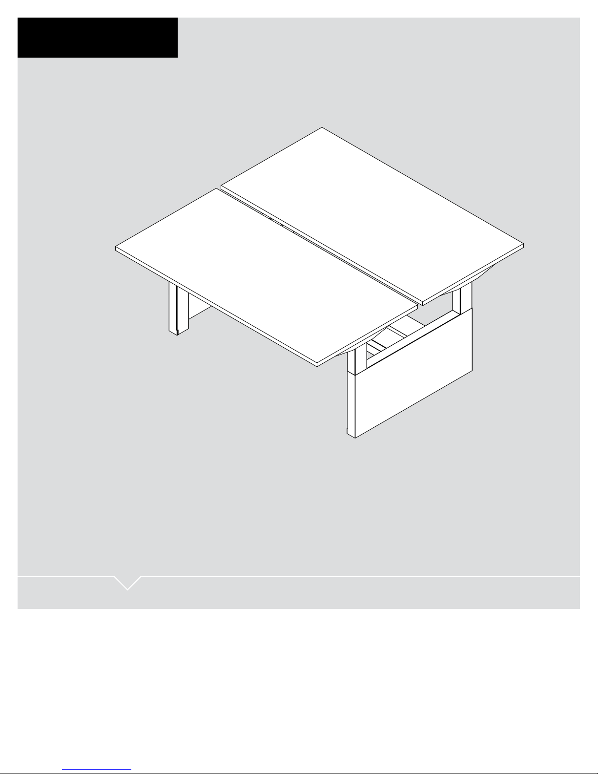
OV1016 | Part No. 86042
OV1016
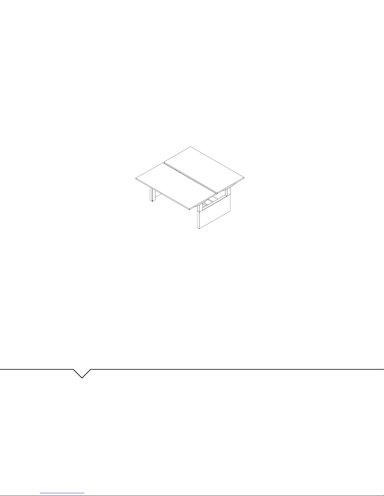
HEIGHT ADJUSTABLE BENCHING SYSTEM
USER GUIDE
Page 2
PRODUCT OVERVIEW
User Guide: OV1016
OV1016
HEIGHT ADJUSTABLE BENCHING SYSTEM
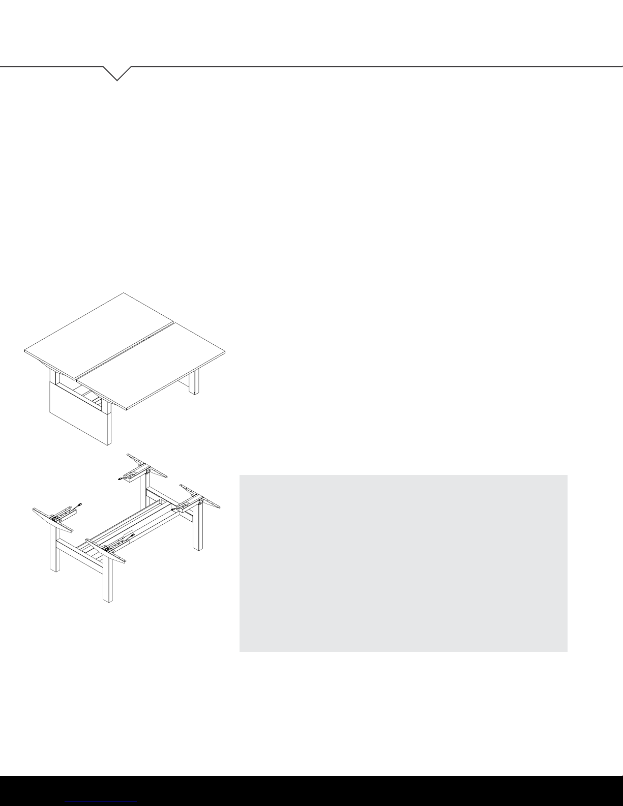
Our best-selling value table base is now available in a back-to-
back benching system. OV1016 can convert your workspace into
a more pleasing open plan, affording you an efcient use of space
proven to increase collaboration at an unheard of price point.
Attractive, highly functional with built-in wire management and
proven to be among the quietest in the industry... all reasons the
OV1016 benching system is a top choice for your workspace needs.
FEATURES
• Back-to-back benching unit, full table bases
(add your own work surfaces)
• Meets BIFMA X5.5 standards
• UL 962 approved
• Integrated wire management
• Holds up to 200 lb. per worksurface
2 | OV1016
Page 3

User Guide: OV1016
TABLE OF CONTENTS
TABLE OF CONTENTS
Parts Diagram 4
Safety Information 5-6
Assembly Instructions 7-13
Electrical Installation 14
Operation 15-16
Initialization and Reset 15
Handswitch Operation 15
Programmable Handswitch Operation 15
- Change the Height Unit 16
- Adjust Height Display 16
- Save Memory Position 16
- Recall Memory Position 16
Troubleshooting 17-18
Unit Errors 17
Handswitch Errors 18
Technical Data 19
Customer Service 19
Standards & Certications 19
This manual explains how this sit-stand desk is assembled, used, and maintained.
All sit-stand tables are subjected to functional and quality tests before leaving
our facility.
OV1016 | 3
Page 4
PARTS DIAGRAM
OV1016
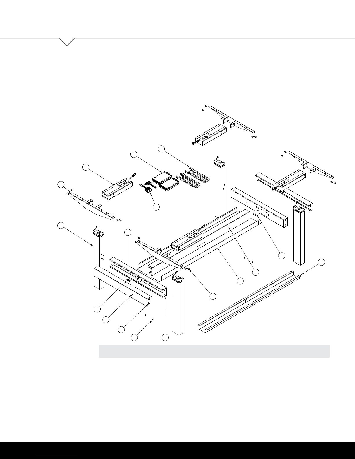
PARTS DIAGRAM
User Guide: OV1016
14
1
3
2
11
12
16
15
10
17
6
7
9
5
PARTS Qty/Package
1. Independent Beam 4
2. Column 4
3. Top Support 4
4. Ganging Bracket 2
5. Cover 2
6. U-Channel 1
7. Cable Tray 1
8. M8-1.25 Tooth Lock Washer Nut 4
9. M8-15x12mm Screw 16
4 | OV1016
8
13
4
Qty/Package
10. M8-1.25x16mm Screw 4
11. M8 Split Washer 4
12. M8 Nut 4
13. M4-0.7x6mm Screw 4
14. Control Box 2
15. Handswitch 2
16. Power Cord 2
17. HAT Channel 2
(for tables equal or greater than 72")
Page 5
User Guide: OV1016
1"
1"
1"
1"
1"
1"
SAFETY
INFORMATION
IMPORTANT SAFETY INSTRUCTIONS Save these instructions.
SAFETY INFORMATION
DANGER
Always unplug this furnishing from the electrical outlet before cleaning.
WARNING:
follow this safety information and the provided instructions when assembling this product.
Do not change or replace components and accessories provided by OMT-Veyhl.
To reduce the risk of electric shock:
To reduce the risk of death, serious injury, or property damage, read and
INSTALL ONLY APPROVED WORK SURFACES
This table system does not include a work surface (desktop). Work surface must be at least ¾" thick and weigh no
more than 5 lb. per square foot (For example, a 2'x6' desktop should weigh no more than 60 lb). Do not exceed a
maximum weight for the desktop of 75 lb. To prevent table from tipping or collapsing, make sure the desk frame
is not overloaded by the weight of tabletop and objects you plan to put on the table. If you are unsure, contact
customer service.
KEEP AWAY FROM CHILDREN
This table system is not designed for use in homes or other areas accessible by small children.
For indoor commercial ofce use only.
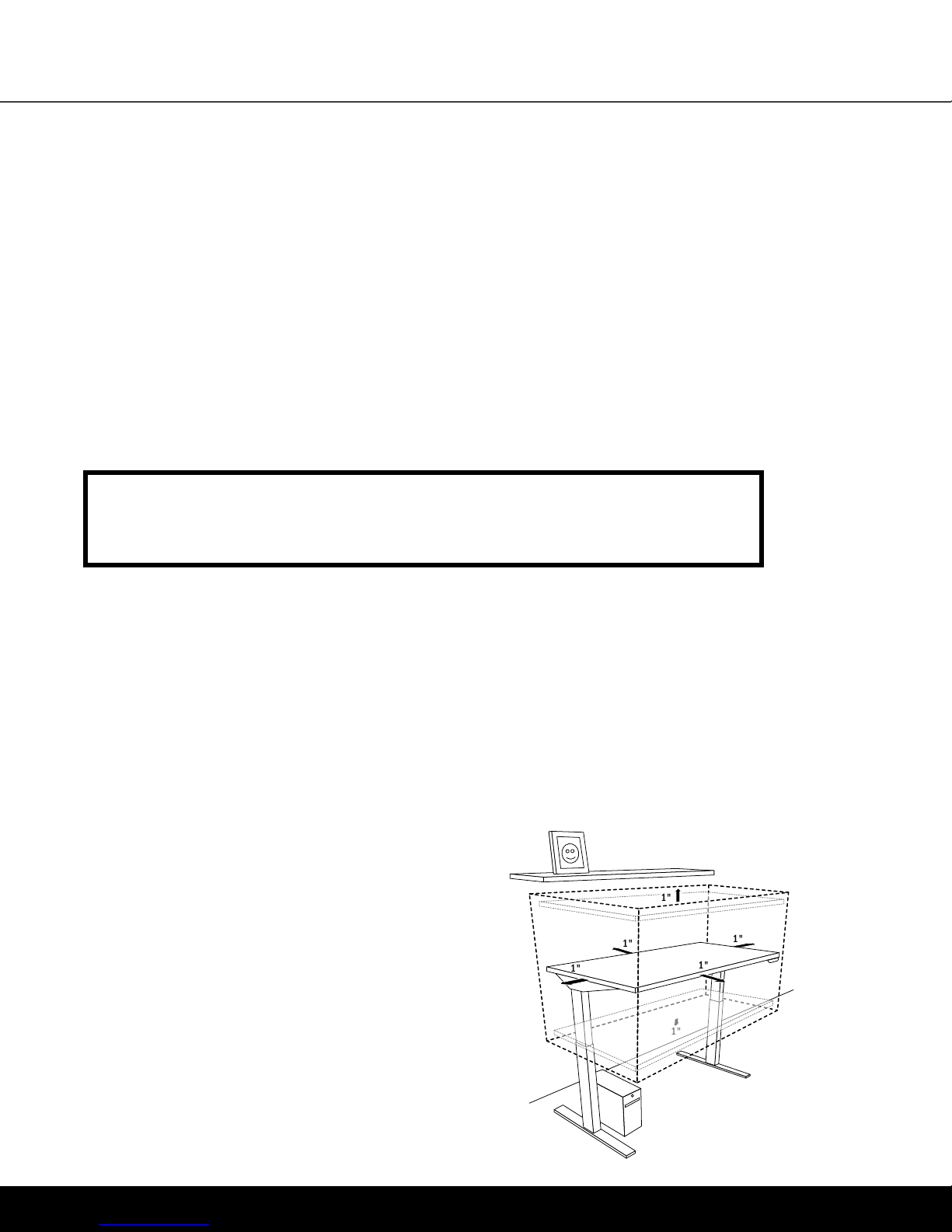
BE CAREFUL WHEN ADJUSTING DESK HEIGHT
Body parts and property can be caught between the
moving work surface and an immobile obstacle (such as
shelves, furniture, window sills, or walls). Keep at least
one inch of clearance around desk and make sure nothing
is in table’s path for its entire range of motion.
Before raising or lowering:
• Check surroundings on all sides of desk are clear
• Make sure corded objects will not be pulled off table
or cause other objects to fall
• Make sure desk power cord moves freely
as desk moves up and down
OV1016 | 5
Page 6
SAFETY INFORMATION
DO NOT OVERLOAD DESK
To prevent table from tipping or collapsing, make sure the desk frame is not overloaded by the weight
of tabletop and objects on table. Evenly distribute load; excess loads near edges can reduce stability
and lead to tip over.
• Do not exceed maximum load (including weight of desktop) of 200 lb. (91Kg) for two-leg conguration,
and 250 lb. (113 Kg) for three-leg conguration
• Do not exceed edge load of 25 lb. when positioning monitors or mounting accessories.
• Do not sit or stand on table
USE CARE WHEN MOVING DESK
• Clear objects and equipment from table before rolling to reduce the risk of tipping over.
• Adjust the desk to its lowest height before moving
• To disconnect, turn all controls to the off position, then remove plug from outlet
• Do not move a loaded desk
• Do not lift the desk by the work surface (desktop)
User Guide: OV1016
DO NOT OPEN ELECTRICAL COMPONENTS
Do not attempt to service table components. There are no user-serviceable parts inside the motor control
units or table legs. If your table needs service, contact customer service. Never operate this furnishing if
it has a damaged cord or plug, if it is not working properly, if it has been dropped or damaged. Return the
furnishing to a service center for examination and repair.
KEEP TABLE FRAME DRY
Keep all electrical components away from water and high humidity. Clean only with a dry or
slightly damp cloth. Do not spray cleaning solutions directly onto table system.
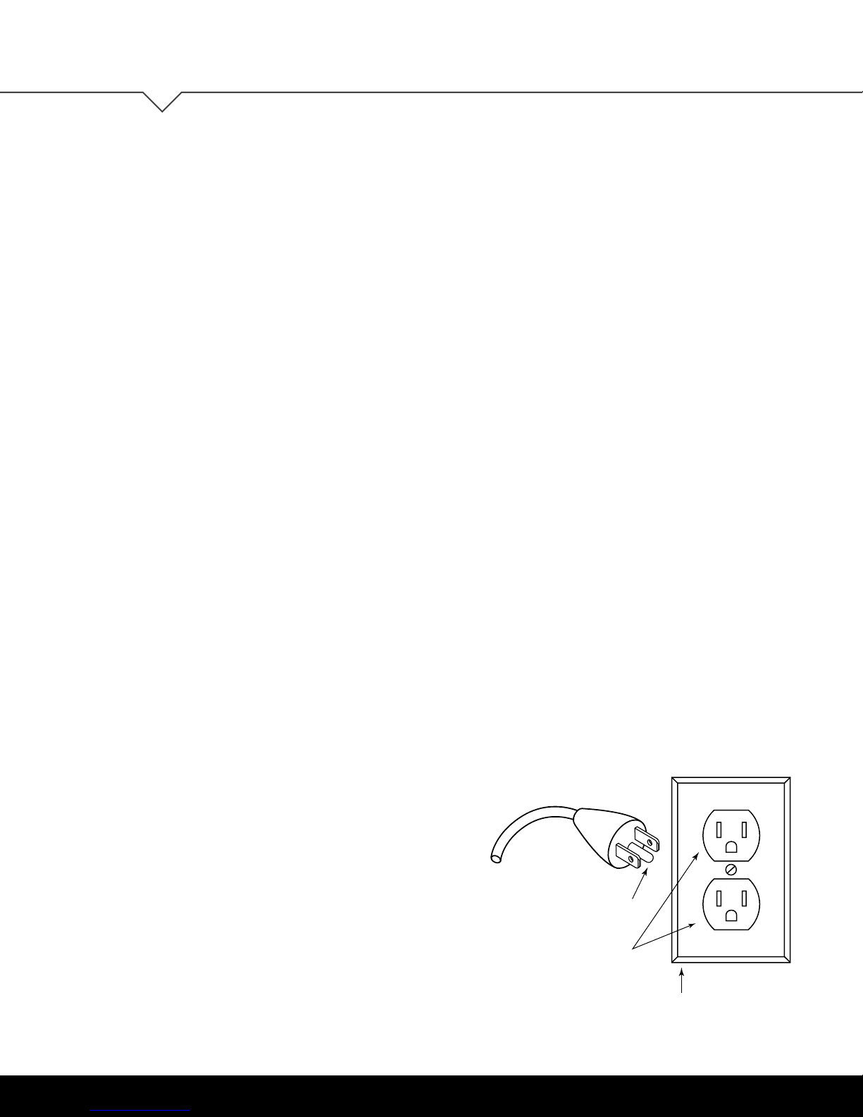
GROUNDING INSTRUCTIONS
ILLUSTRATION A
This product is equipped with a cord having an
equipment-grounding conductor and a grounding plug.
Use only the cord provided. Make sure that the product
is connected to an outlet having the same conguration
as the plug (as shown in Illustration A) that is properly
installed and grounded in accordance with all local
codes and ordinances.
Grounding
Pin
Do not modify the plug provided with the product
– if it will not t the outlet, have a proper outlet
installed by a qualied electrician.
No adapters are to be used with this product.
Keep cord away from heated surfaces.
6 | OV1016
Grounded
Outlet
Grounded Outlet Box
Page 7

User Guide: OV1016
ASSEMBLY
INSTRUCTIONS
The assembly of the table frame to be made in accordance with this manual.
Changes to the table frame or improper use may affect the safety, function, and life of your product.
This manual is for all sit-stand tables from the OV1016 series.
Due to different models or types, pictures may vary.
ASSEMBLY INSTRUCTIONS
ASSEMBLY OVERVIEW
1. Assemble the ganging bracket
2. Assemble the top support to the beam and column
3. Assemble the cable tray
4. Fasten the wire management to the ganging brackets
5. Snap on the ganging bracket covers
6. Fasten the table frame on to the table top
7. Fasten the control box and handswitch to the table top
8. Connect the motor cables to the control box
9. Connect the handswitch (HS) cable to the control box
10. Connect the supplied power cord (AC) to the control box
11. Attach all cables to the table frame or the underside
of the table top
12. Connect side-by-side benches
If you have any difculty assembling this unit, or need to order
replacement parts, please contact our Customer Service department.
Use the parts diagram on page 4 as a reference.
OV1016 | 7
Page 8
ASSEMBLY INSTRUCTIONS
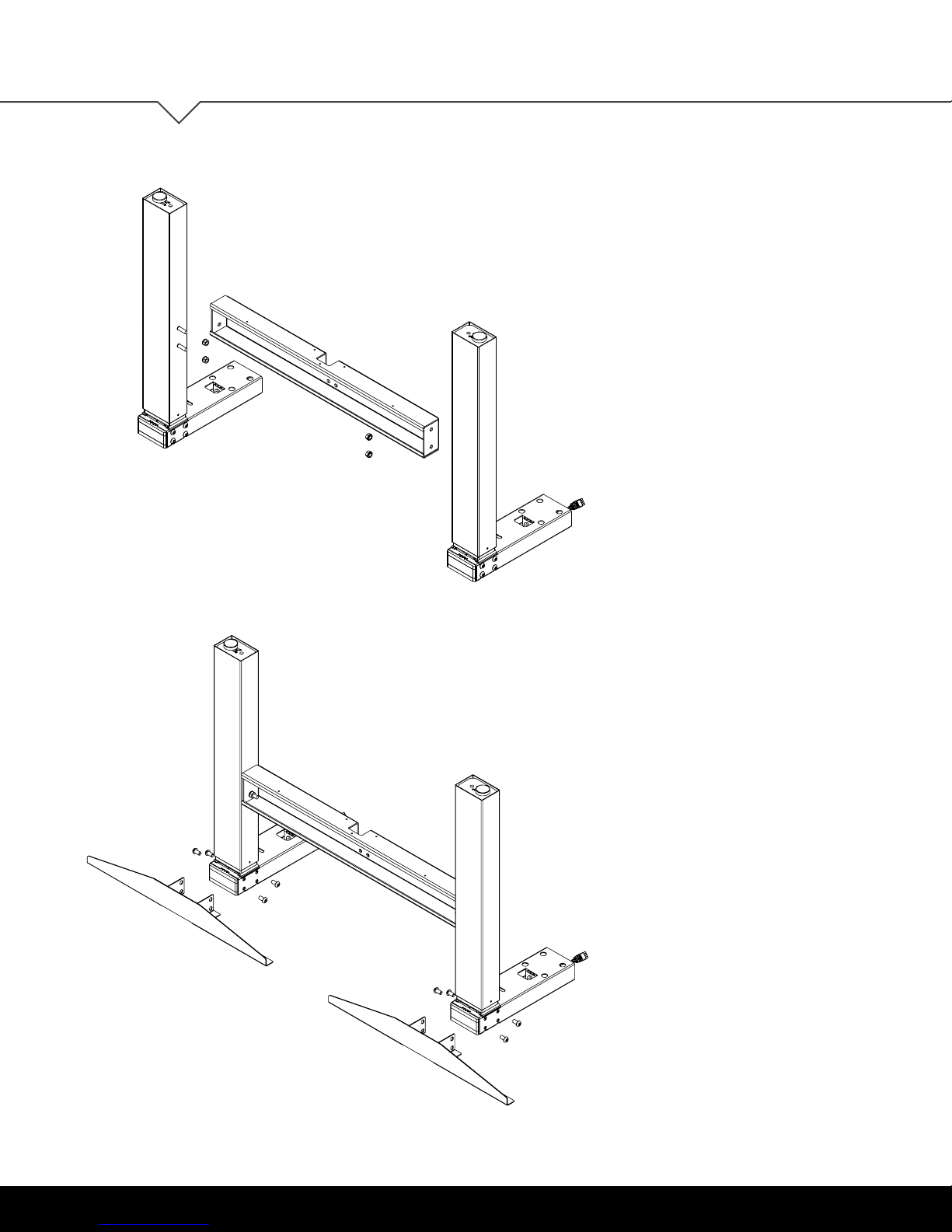
ASSEMBLE THE GANGING BRACKET
Assemble using the M8-1.25 Tooth Lock Washer
1
Nut (2 per column). The maximum tightening
torque for these nuts is 15.8Nm (10 ft-lbs).
Repeat for remaining columns.
User Guide: OV1016
ASSEMBLE THE TOP SUPPORT TO THE
BEAM AND COLUMN
2
Remove tape from column assembly. Assemble
using the M8-1.25 x 12mm length screws (4 per
column). Hand-tighten only (do not torque until
after table top is attached). Align top support
holes with independent beam assembly.
Repeat for remaining columns.
8 | OV1016
Page 9
User Guide: OV1016
3A
3B
ASSEMBLY INSTRUCTIONS
(FOR ELECTRICAL SYSTEM UPGRADE ONLY)
ASSEMBLE ELECTRICAL
See page 14
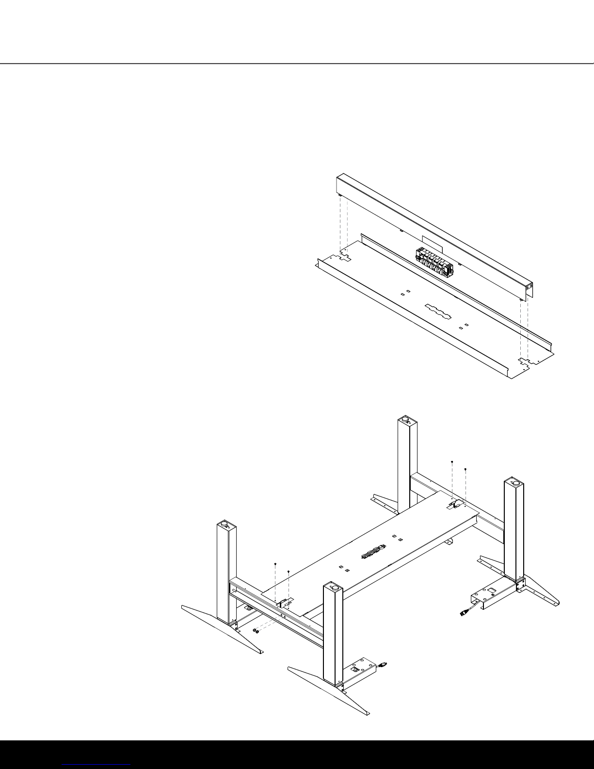
ASSEMBLE THE CABLE TRAY
Align and insert the tabs on the u-channel into
the tray. Squeeze the u-channel so that all tabs
are secured into the tray.
FASTEN THE CABLE TRAY ASSEMBLY ONTO THE GANGING BRACKETS
Attach the tray to the ganging brackets using the M4-0.7x6mm length screws.
4
The maximum tightening torque for these screws is 4Nm (35 in-lbs).
Attach the u-channel to the ganging bracket using the M8-1.25x16mm
length screws, M8-1.25 nut, and M8 lock washer (2 per ganging bracket).
The maximum tightening torque for
A socket wrench is recommended
Repeat for both sides.
these screws is 20Nm (14.8 ft-lbs).
for this step to hold the nut in place.
Shown upside down for better view.
Table to be assembled in upright position.
OV1016 | 9
Page 10
ASSEMBLY INSTRUCTIONS
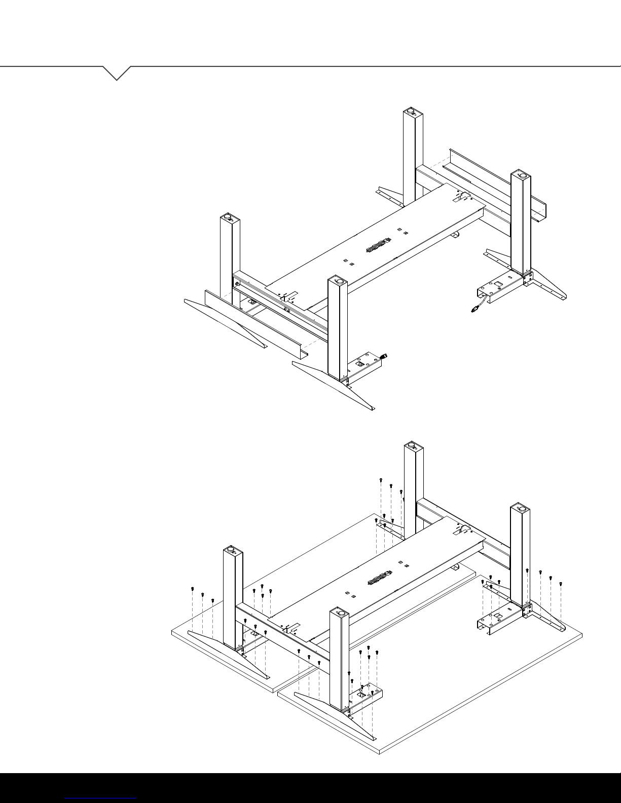
SNAP ON THE GANGING BRACKET COVERS
The covers will self-secure when snapped on to the
5
ganging brackets.
User Guide: OV1016
FASTEN THE TABLE FRAME ONTO THE TABLE TOP
Attach table frame onto the table top, making sure that
6
the legs are perpendicular to the table top. Be sure to
use approved screws per the table top supplier. Once
the table top is attached, torque the hand-tightened
screws in the top support. The maximum tightening
torque for these screws is 24Nm (18 ft-lbs).
*
Shown upside down for better view.
Table to be assembled in upright position.
10 | OV1016
Page 11
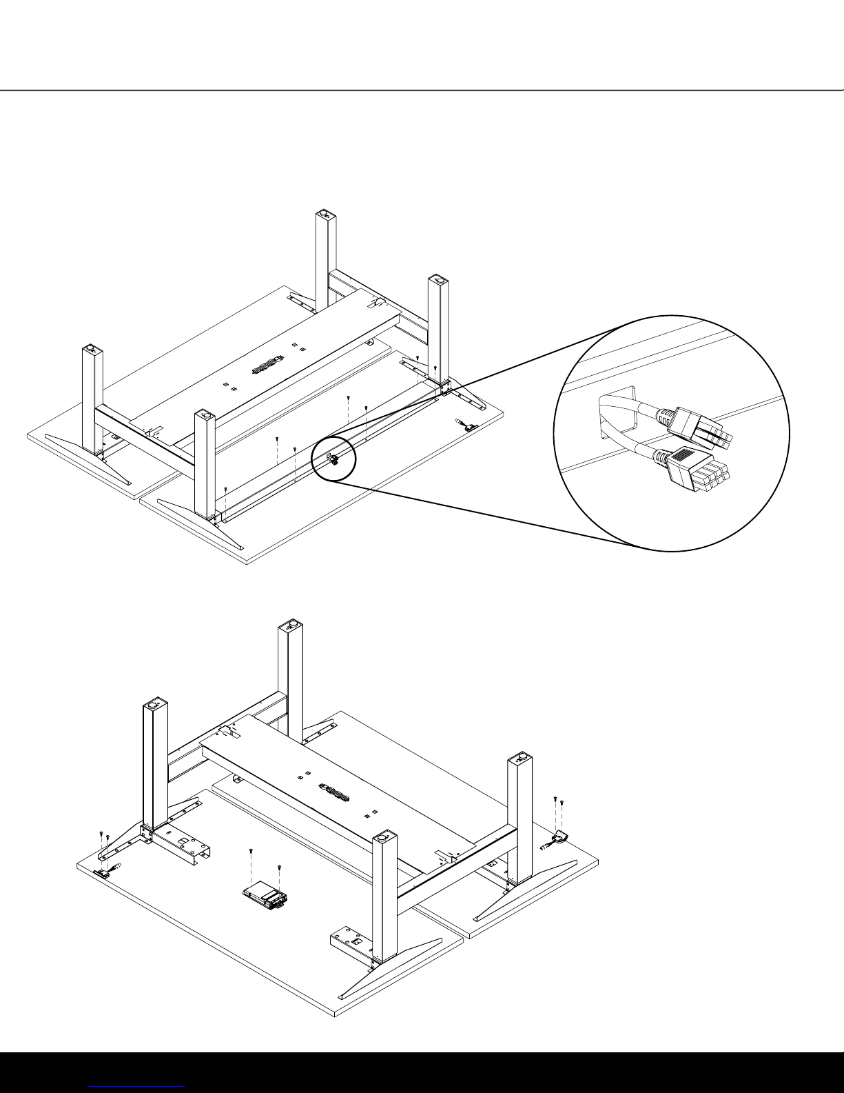
User Guide: OV1016
6B
ASSEMBLY INSTRUCTIONS
(FOR TABLES EQUAL OR GREATER THAN 72")
ATTACH THE HAT CHANNEL
Feed the motor cables through the HAT channel cut out.
FASTEN THE CONTROL BOX AND
HANDSWITCH TO THE TABLE TOP
7
Make sure the control box and handswitch are
fastened in a location where all the cables will
connect without being in tension. Be sure to use
approved screws per the table top supplier.
OV1016 | 11
Page 12
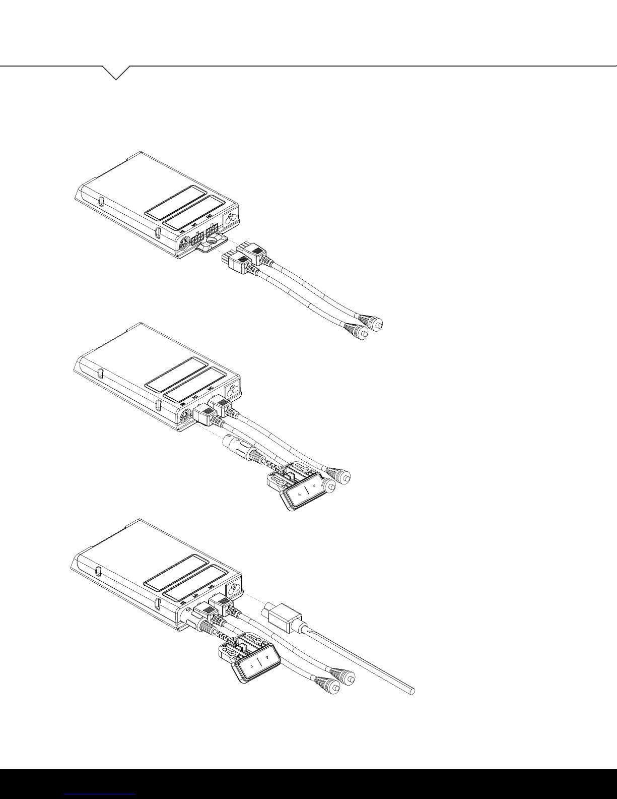
ASSEMBLY INSTRUCTIONS
CONNECT THE MOTOR CABLES
TO THE CONTROL BOX
8
The motor cable plug-connection has to click into
place. If a control box is used which has more
plug-terminals than needed, you have to connect
to M1 rst. (The extra terminals can be left open.)
Connections to the control box:
M1-M2 = Connectors for the columns
HS = Connectors for the handset
AC = Connector for the power cord (3-pin)
User Guide: OV1016
CONNECT THE HANDSWITCH (HS) CABLE
TO THE CONTROL BOX
9
CONNECT THE SUPPLIED POWER CORD
10
(AC) TO THE CONTROL BOX
12 | OV1016
Page 13
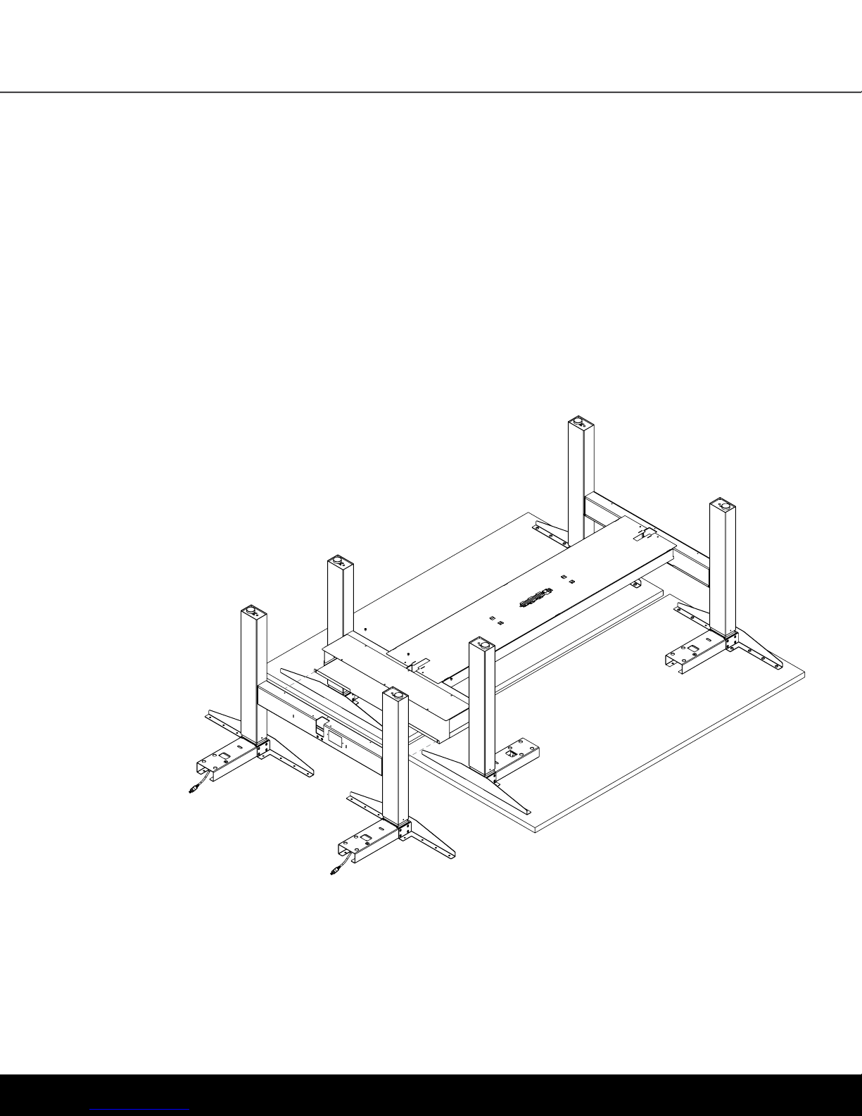
User Guide: OV1016
11
12
ASSEMBLY INSTRUCTIONS
ATTACH ALL CABLES TO THE TABLE FRAME
OR ON THE UNDERSIDE OF THE TABLE TOP
Attach cables in order to avoid any damage during operation.
Be sure to leave enough slack in the cables to allow for the
table to move into it’s highest position.
CONNECT SIDE-BY-SIDE TABLES*
*For units specied to use a side-to-side connector, attach
lower tray to the bottom of the ganging bracket of each
bench using the M4-0.7x6mm length screws. The maximum
tightening torque for these screws is 4Nm (35in-lbs).
Once installed, the upper tray can be slid on to t.
OV1016 | 13
Page 14
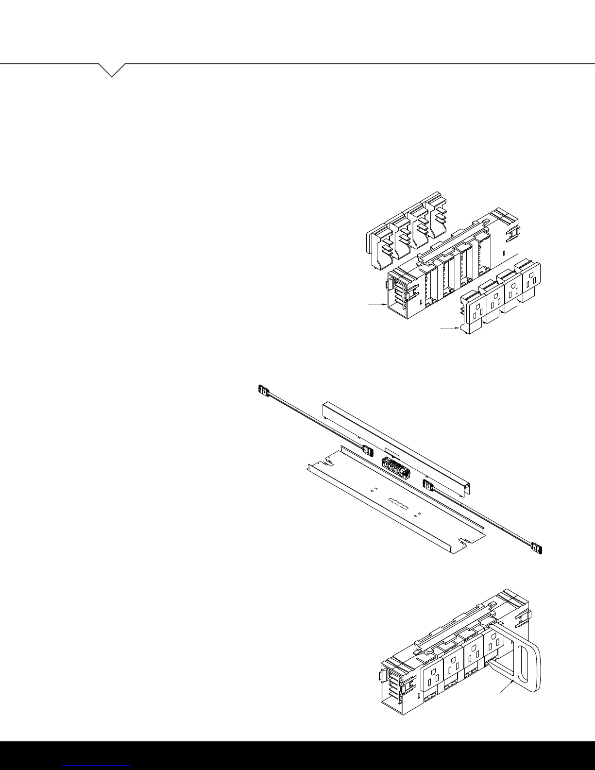
ELECTRICAL INSTALLATION
Simplex Receptacles
Power Block
Block Latch
Cable Latch
Mounting Bar
ELECTRICAL INSTALLATION
(FOR TABLES ORDERED WITH THE ELECTRICAL SYSTEM UPGRADE)
INSTALL SIMPLEX RECEPTACLES
INTO POWER BLOCK
Insert terminals into corresponding slots in block and seating
receptacle until catches engage on
Note: a noticeable “snap”
fully engaged into block. Ensure terminals go directly into
slots and do not get inserted into an adjacent slot.
User Guide: OV1016
both sides of receptacles.
will be heard when receptacle is
Power Block
Simplex Receptacles
CONNECT CABLES TO BLOCK
Connect as required (not shown). Ensure cables are completely seated under cable latches
and into block. Power disruption may occur if cables are not fully seated into block.
INSTALL POWER BLOCK INTO TRAY
Place the power block into the provided
cut-out in the tray and slide the block to
lock it into place.
INSTALL U-CHANNEL TO TRAY
Remove the punch-out features from both sides
of the u-channel. Power block will wedge into
the channel between the punch out features,
secure by squeezing the u-channel and locking
the tabs into the tray.
For Simplex Receptacle Removal
Insert ends of Simplex removal tool into slots above and below
receptacle (shown) and push rmly into block until it catches on tool,
snap over receptacle edges. Pull receptacle tool and receptacle
straight out of the block. Note: Simplex removal tool sold separately.
14 | OV1016
Simplex Removal Tool
Page 15
User Guide: OV1016
OPERATION
INFORMATION
INITIALIZATION/RESET
The desk may need to be initialized/reset after any of the following:
- After assembly
- After disconnection from the power supply
- After any impact on the table top.
OPERATION INFORMATION
To initialize/reset, you will need to move the table to the lowest position by holding the DOWN button of
the handswitch until all columns reach the lowest position. Then press the DOWN button again and hold it
pressed for ve seconds or until a slight movement of the table drops down to the machine zero point and
back up to the operation zero point. Once the table stops moving, release the DOWN button. If the button is
released too early, this leads to a malfunction of the table and you must repeat the reset process.
The upper height position is programmed into the control box. For this reason, only use the control box that
has been provided with the specic table frame. Under no circumstance should a control box from one
table be moved to another.
NORMAL HANDSWITCH OPERATION (for all handswitch types)
By pressing the UP or DOWN buttons, the table will move up or down to the desired position. Once the desired
position is reached, let go of the UP or DOWN button. The table will stop once it reaches the lower or upper
height position.
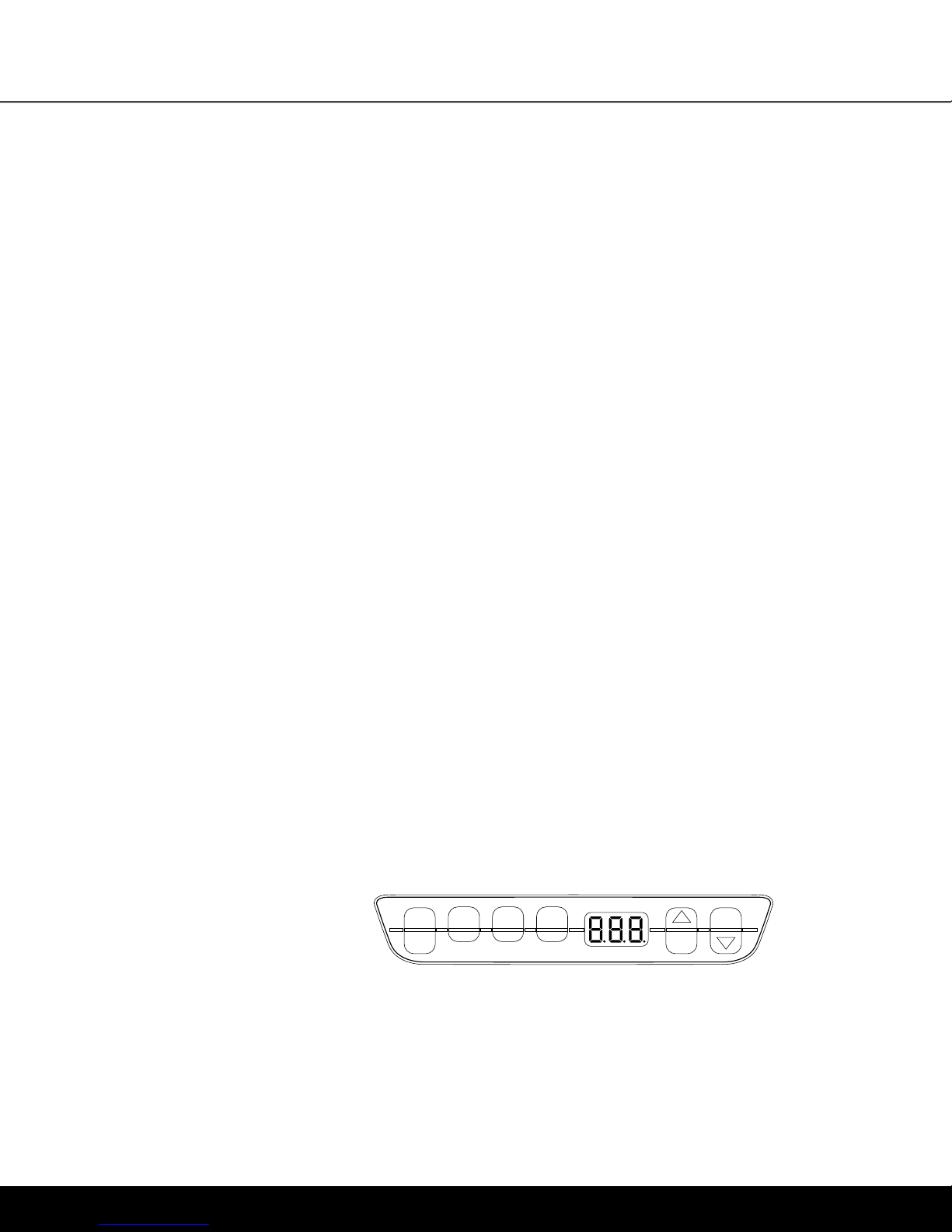
PROGRAMMABLE HANDSWITCH OPERATION (optional)
This programmable handswitch is
1
equipped with a display for showing
the current table height in centimeters
or inches.
2 3 4
s
The handswitch also will display an error code if an error is detected by the control box. When an error
is detected, the display will show an error code “EXX,” instead of the current table height. To resolve the
error, see the Troubleshooting Section (p. 17-18 of this guide).
The programmable handswitch also has the ability to save up to four different height positions.
OV1016 | 15
Page 16

OPERATION INFORMATION
PROGRAMMABLE HANDSWITCH OPERATION (continued)
CHANGE THE HEIGHT UNIT (inches or centimeters)
The height display of the handset can display either centimeters or inches. With the help of the S5-menus, the
unit can be changed. If the display was originally set to centimeters, then after the procedure noted below it
will change to inches or vice versa.
User Guide: OV1016
To change the unit, follow these steps:
1. Press and hold the 1, 2, and UP buttons for 5 seconds until the display shows “S 5”.
2. Conrm by pressing the “S” button. Now the display will have changed.
To exit the menu without making a selection, wait approximately 10 seconds until the height display appears
again.
ADJUSTMENT OF THE HEIGHT DISPLAY
If the indicated value does not match the actual height of the table top, the display can be corrected as follows:
1. Press and release the “S” button.
2. Press and hold the DOWN button for 5 seconds until the display starts to ash.
3. Measure the table height and enter the measured value (depending on the setting in centimeters or inches)
with the UP or DOWN button. Conrm the entry by pressing the “S” button.
To exit the menu without making a selection, wait 10 seconds and the height display will appear again.
SAVE MEMORY POSITION
Drive the table up or down to the desired height. Press the “S” button (in the display “S -” is shown.) Select a
position by pressing on any of the four number buttons, 1-4, (the display will show the setting as “S1”).
The save position procedure is conrmed by the control box with a double click sound. After approximately
5 seconds, the display shows the current table height. Repeat steps to save a maximum of four different
positions.
RECALL MEMORY POSITION
Press and hold the desired memory location button (1, 2, 3 or 4) and the table moves independently from the
current position into the saved position. The button must be pressed until the position is reached. If the button
is released, the table will stop short of the desired height.
16 | OV1016
Page 17
User Guide: OV1016
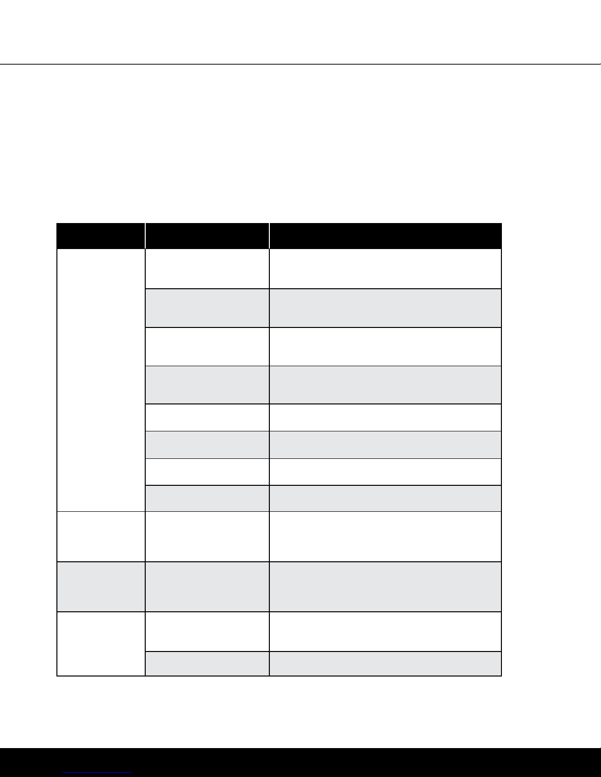
TROUBLESHOOTING
UNIT
TROUBLESHOOTING
ERROR CODE
Table does not
move
SOURCE SOLUTION
No power supply Plug in the power cord or check the connection
on the control box
No connection or a loose
connection to the drives
No connection or a loose
connection to the handswitch
Max lifting capacity
is exceeded
Max time limit is exceeded Control is activated automatically after approx. 9 minutes
Defective drive Contact customer service
Defective control box Contact customer service
Handset is defective
Verify the plug connections of the motor cable
to the control box
Verify the plug connections of the motor cable
to the control box
Reduce the weight or load on the desktop
Replace the handset
Table moves
down at a
slow rate
During operation,
tables moves at
a slow rate
Table moves
on one side only
briefly and then
stops
Control box expects
new reset
Max lifting capacity
is exceeded
No connection or a loose
connection to the drives
Defective drive
Reset control box. (See page 15)
Reduce weight
Verify the plug connections of the motor cable
to the control box and reset the control box
Contact customer service
OV1016 | 17
Page 18
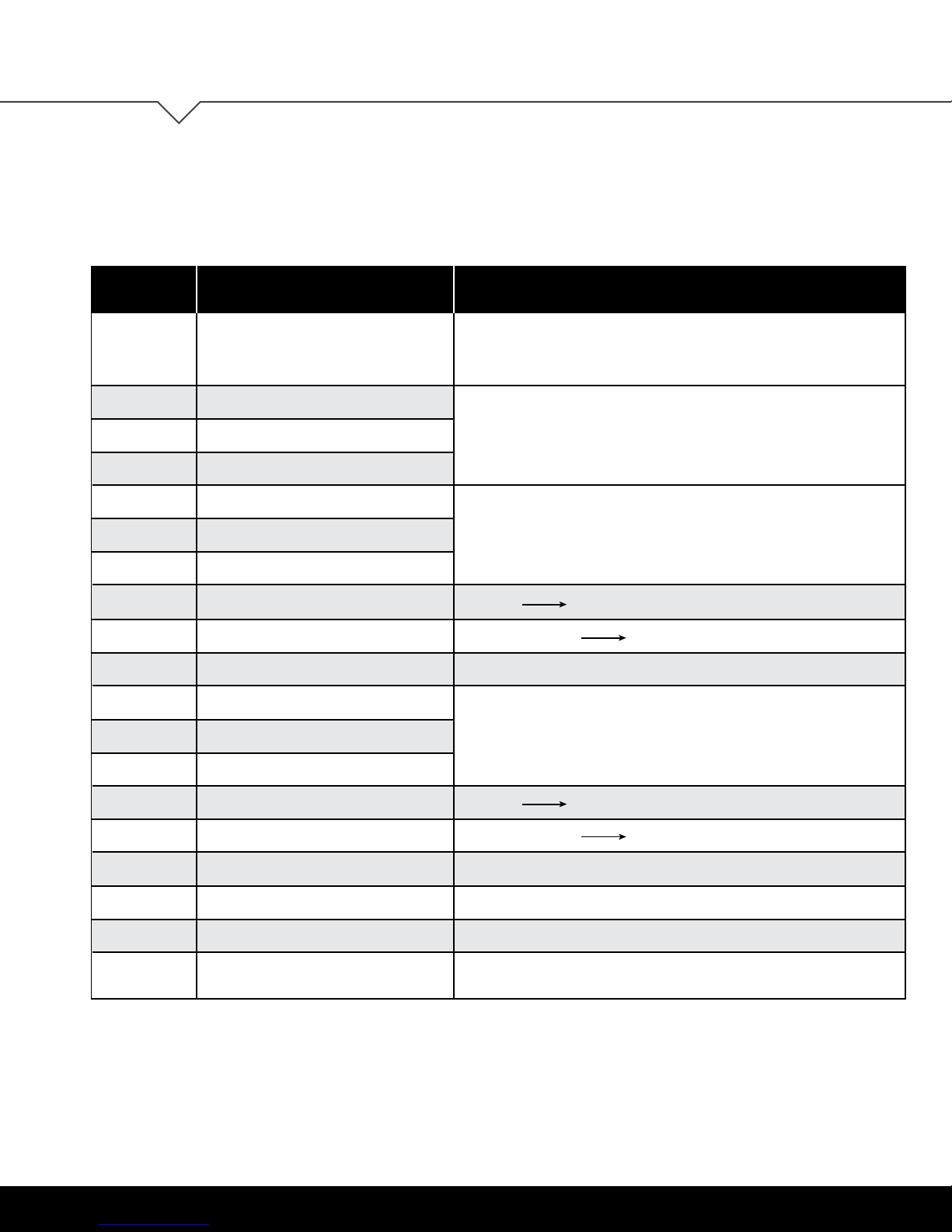
TECHNICAL DATA
HANDSWITCH DISPLAY
User Guide: OV1016
ERROR CODE
HOT
E00
E01
E02
E12
E13
E14
E24
E25
E26
E36
E37
E38
SOURCE SOLUTION
The control box monitors the duty
cycle (time-controlled) and its max
temperature. A value has been exceeded.
M1 – Internal Fault
M2 – Internal Fault
M3 – Internal Fault
M1 – Defect
M2 – Defect
M3 – Defect
M1 – Overcurrent
M2 – Overcurrent
M3 – Overcurrent
M1 – Not connected
M2 – Not connected
M3 – Not connected
Wait until the “HOT” display goes out - the table is working properly again
Unplug and contact customer service
Unplug.
Correct the external short circuit and/or verify the cable to the drives.
Plug cables into the control box and re-run table.
Collision resolve if necessary
Max load exceeded remove excess load from the table
If the problem still exists, please contact customer service
Motor not connected.
Check cable / connector to the drive.
Reset the table (see page 15).
E48
E49
E55
E56
E60
E61
If it is not possible to resolve an error as described, disconnect the power cord, wait a few minutes and reset the table again.
If the error still occurs, remove the table from the power source and contact customer service.
(Error Code list is valid from rmware 1.7.5 and higher)
18 | OV1016
Overcurrent drive 1
Overcurrent drive 2
Drive 1 - Synchronization is lost
Drive 2 - Synchronization is lost
Collision identified
Drive replaced
Collision resolve if necessary
Max load exceeded remove excess load from the table
If necessary, reduce the load on the table
Reset the table (see page 15).
Option ISP function. Remove source.
The connection to the drive is interrupted or a new drive is connected.
Reset the table (see page 15).
Page 19
User Guide: OV1016
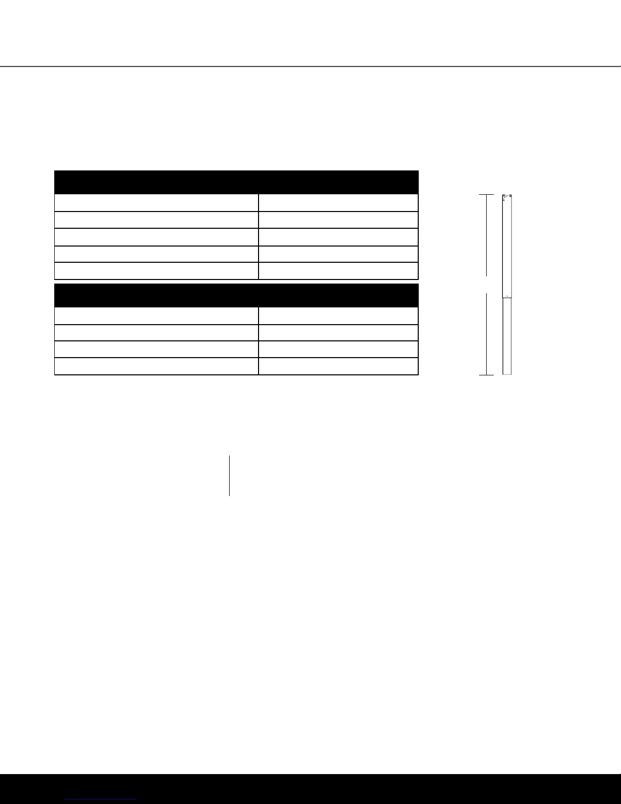
TECHNICAL DATA
TECHNICAL DATA
GENERAL CONTROL BOX
Power supply
Standby power consumption, primarily
Operating temperature
Protection class
Maximum power output
TWO-COLUMN FRAME WITH CONTROL BOX
Maximum lift capacity
Adj. range, depending on version
Maximum input current
Maximum duty cycle
120 VAC ±10% / 60 Hz
<0.3 W
0-35°C
IP 20
216VA/24V
200 lb (≈ 90 kg / 890N)
View Illustration B
5 A
10% (2 min. on / 18 min. off)
CUSTOMER SERVICE
If you have any problems with
your table base, please contact
our service department.
PHONE: 1-616-738-6688
FAX: 1-616-738-6682
ILLUSTRATION B
stroke length
18.9"
STANDARDS &
CERTIFICATIONS
The drive system is tested according to
the following standards:
UL 962
Issued: 2014/11/07
Ed: 4 Household and Commercial Furnishings
CSA C22.2#68
Issued: 2009/09/01 Ed: 7 (R2014)
Motor-Operated Appliances (Household and Commercial);
Gen. Inst. No.1: 2010, Gen. Inst. No.2: 2010
Meets 2014 BIFMA standards.
WARRANT Y
CONTACT YOUR SALES REPRESENTATIVE
FOR WARRANTY INFORMATION
INTERTEK LISTING BELONGS TO:
System: Clever Bench
OMT-Veyhl USA
11511 James Street
Holland, MI 49424
OV1016 | 19
Page 20
OV1016
USER GUIDE
Part No. 86042
Rev 020818
 Loading...