

Page 1
EMERGENCY HELP DIALER
MODEL 911 II
Operation and Instruction Manual
Suitable for home-alone elderly or single persons, recovering
patients, disabled persons,
small businesses etc.
Important information and instructions for your
Emergency Help Dialer ( EHD )
Please keep this booklet in a readily accessible place
Page 2

PLEASE READ CAREFULLY
Contents
Pg. 2 *Features, Emergency Dialer Components, and
DISCLAIMER
Pg. 3 *Precautions and Maintenance
Pg. 4 *Names and Functions of each part
Pg. 5 *Installation and Functioning test of the main unit
Pg. 6 *Procedure for storing phone numbers and recording messages
Pg. 7 *Procedure for storing phone numbers and recording messages
continued
Pg. 8 *Procedure for storing phone numbers and recording messages
continued
Pg. 8 *Retrieving the setting contents, Description of Quick Function
commands
Pg. 9 *Operation Directions for 2 Way Communication
Pg. 10 *Operation Directions for 2 Way Communication
continued
Pg. 11 *Testing and Replacing Battery
Pg. 12 * Specifications and Approvals
Pg. 13 *Warranty and contact details
1
Page 3

Features
2
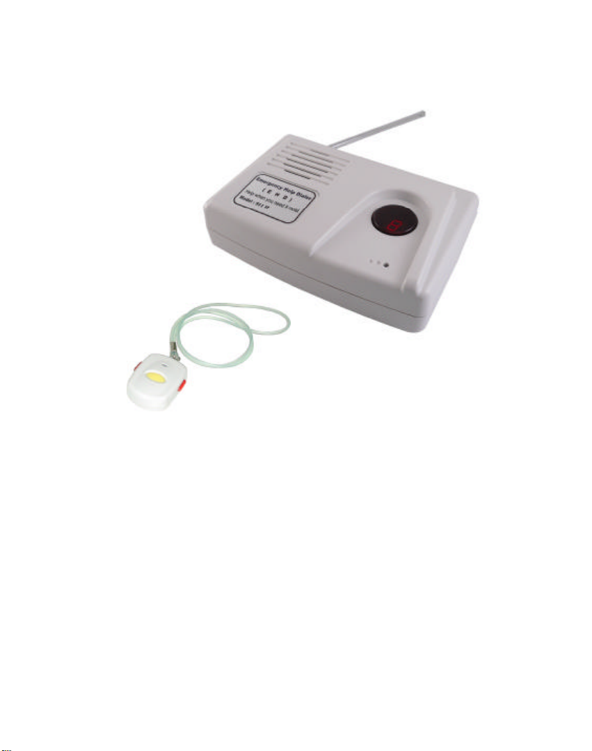
Congratulations, you have purchased a high quality Emergency Help Dialer
(EHD) which is easy to program and lets you call for help when you cannot
dial the phone yourself. When you are in need of help, gently, but firmly
push the two red panic buttons of the wireless EHD pendant. Using your
existing telephone line, the console when activated will receive the signal
and dial up to 5 pre-set phone numbers and play the message you have
recorded. If a call is not answered, then the console will sequentially move
on to dialing the next number, until all 5 numbers have been called. On the
unlikely event that none of the numbers called have answered the console
will repeat this sequence once more. When a call is answered the receiver
will hear your pre-recorded voice message requesting immediate assistance.
The console is programmed to recognize that the call is being answered by a
live person.
Emergency Dialer Components:
1. One main dialing console
2. One Wireless Waterproof Pendant
3. One AC/DC adaptor
4. One modular line cord
5. One rechargeable 9 volt battery
6. One plastic necklace
7. One wrist band
8. One owner’s manual
Disclaimer:
Under no circumstances should this Emergency Help Dialer (EHD) be
solely relied upon in life threatening circumstances. Using EHD completely
indemnifies the Manufacturer and/or its selling agents from any legal action
for whatever reason.
Page 4

Precautions & Maintenance
1. To reduce the risk of electric shock do not remove cover or back of the
console.
2. Keep the product from being installed at places liable to dirt, high
temperature, moisture and sun exposure, avoid heavy blows or dropping.
3. The placement of the main unit is closely related to its receiving range.
To attain the best efficiency of application, try to avoid placing the main
unit on electrical appliances (such as TV sets, computers, motors) as well
as metal cabinets. It is also inappropriate to place it in the corner or on
the floor.
4. This unit calls out and plays the message through a regular telephone set.
If the telephone set has both Tone / Pulse dialing types, set it to "Tone".
5. Dialer will not work with a cordless phone that requires an AC adaptor
when their is a power outage. You must use regular phone.
6. To have the surveillance feature, an answering machine will not operate
or be able to receive any incoming messages. This is only for incoming
calls and does not affect the 2 way communication on out going calls
during the emergency operational phase. You can answer your phone
during the ringing. It will stop ringing after 5th ring and the surveillance
mode will take affect.
3
Page 5
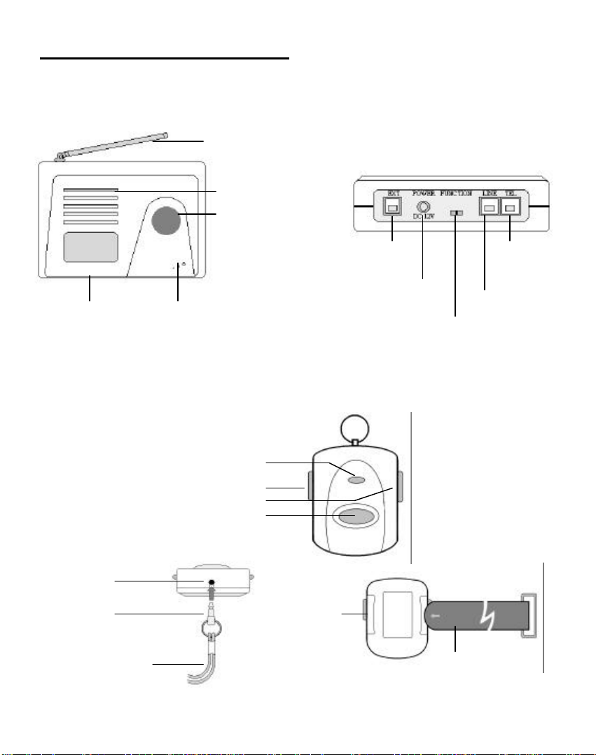
Names and Functions of Each Part
set
jack
Necklace
1. Main Unit (Power Supply : 12VDC Adaptor/500mA)
Antenna
Battery Cap
Internal Mic
Speaker
Action Indicator
/ Panic Button
EXT : Alarm jack
DC Power jack
Telephone
line jack
2. Wireless Help Caller (Power Supply : 12V Battery (Alkaline Battery
Recommended) Size 23A (Included)
Action Indicator
Phone
Hole
Pin
Red Panic Button
Yellow Call Button
Hole
Wrist Tape
4
Page 6

Installation and Functioning Test of the Main Unit
5
1. Plug one end of the AC adaptor into the “POWER” jack on the back of the
main unit and the other end into an AC outlet that is not switched on or off by
a wall switch.
2. Open the battery cap and place the 9V battery inside.
3. Plug one end of the supplied modular line cord into the jack labeled “LINE”
on the back of the main unit and the other end into a modular phone jack
available in your home.
4. Plug the modular cord line of your home telephone into the jack labeled
“TEL” on the back of the main unit.
5. If you have purchased an extra alarm, either a flash siren or a panic switch,
you can connect it to the “EXT” jack on the back of the main unit. The
interface is on the above.
6. After connecting the main unit, please place the “FUNCTION” switch (on
rear of main unit) to “MUTE” or “ALARM” position. If you press the “Call”
button on the wireless help caller and the main unit beeps, this indicates that
the wireless help caller and the main unit are working.
Note:
ALARM: When function is set to this position, a 15 second siren will go off
when the panic button is pressed and the dialing console will automatically dial
out the phone number you pre-set for help.
Mute: When function is set to this position, there will be no siren. However,
the dialing console will automatically dial out the phone number you pre-set.
Page 7

Procedures For Storing Phone Numbers And Recording Messages
1. Place the “FUNCTION” switch selector on the rear of the main unit to
“SET ”. The main unit will give off a long beep sound. A small red dot will
appear on the indication window, showing that the main unit is properly
connected.
2. Pick up the handset of the telephone that is connected to you Emergency
Dialer.
3. Setting the first set of emergency telephone number
Procedure:
* key + 1 key
Example: If the first help number is 1-980-123-4567, press the “*” key first,
then press the number “1” key, then press the next eleven numbers
“1-980-123-4567”, then press the “#” key to end.
Note:
( 1 ) Pressing “*” key and then “1” key will make the telephone to give off
a long beep sound.
( 2 ) A maximum of 16 digits can be programmed for any one phone number.
If an error occurs, the telephone will give off a beep sound three times
continuously. Press the “#” key to quit and re-set.
( 3 ) After completing setting up the telephone number, press “#” key to
confirm. The telephone will give off two beep sounds. This indicates
the setting of the telephone number is completed. If you intend to
change the telephone number, repeat aforesaid procedure.
( 4 ) If you intend to cancel an existing telephone number, go to step ( 3 )
directly after completing step ( 1 ). The main unit will then no long
forward this number.
( 5 ) Call forwarding for extension is available. Ex. Extension: 123,
Press: *+ 1 + 19801234567 + * + 123 + #
Press “*” key before extension number, one time means postpone 8
seconds, two times to postpone 16 seconds.
( 6 ) The setting procedures for the second, third, fourth and fifth telephone
numbers are the same as before. The emergency telephone numbers
can be set to a regular telephone or a mobile phone.
Phone number
# key
6
Page 8

Continued
7
Message 20 seconds
Password (4 digits)
4. Procedures for recording messages
Procedure:
* key + 6 key
(1) Pick up the handset of the telephone that is connected to the dialer. Be
prepared to speak into the handset.
(2) Press the "*" key and the number "6" key. You will hear a beep sound.
Begin recording immediately after the beep. The recording time is 20
seconds. After completing the message recording, press the "#" key to
confirm. The messages can be changed anytime based on the actual needs.
Sample message:
This is (your name) this is a medical emergency. Please send help. I live at
(your full address and apartment number (if applicable) and any other
information that will be helpful in finding your address). Let the party know
where your key is. For 2 way communication press the "*"' key and begin
speaking, and to end call press the "#" key.
5. How to check your messages
Press the "*" key and the number "7" key. Wait for a beep sound.
Your message will be heard through the telephone handset after the beep.
6. Setting the password
Procedures:
* key + 8 key
Example: If the password is 1234, press the "*" key first, then press the number
"8" key, then press number 1 and 2 and 3 and 4 (4 digits) keys. Then
press the "#" key to end.
# key
# key
Page 9

Continued
9)
7. Setting the time for two way hands-free voice communication
Setting time is from 1 minute to 9 minutes.
Procedures:
* key + 9 key
Example: If the time is to be 3 minutes, press the "*'' key first, then press the
number "9" key, then press the number "3" key, then press the "#"
key to end.
Minutes (1-
# key
Retrieving the setting contents
1.To retrieving the setting contents, press “*” key first and then the “0” key. The
five sets of emergency telephone numbers, the password, and the time for two
way hands-free voice communication will appear on the indicating window.
2.Upon the completion on the setting mode. Place the “FUNCTION” switch to
either the “MUTE” or “ALARM” position.
Description of Quick Function Commands
* 1
* 2
* 3
* 4
* 5
* 6
* 7
* 8
* 9
* 0
Setting the “ 1st ” set of emergency telephone number P1
Setting the “ 2nd ” set of emergency telephone number P2
Setting the “ 3rd ” set of emergency telephone number P3
Setting the “ 4th ” set of emergency telephone number P4
Setting the “ 5th ” set of emergency telephone number P5
Recording your message P6
Check your message P7
Setting the password P8
Setting the time for two way hands-free voice communication P9
Retrieving the setting contents P0
8
Page 10

Operation Directions
1. Application for an in-house call
If you want to call upon someone inside of your home, push the "Call" (Yellow
Button) on the wireless help caller. The dial console will give off a loud beep
sound.
2. Application for an emergency call
When there is an emergency and you need help, push both left and right red
buttons together on the wireless help caller or push "Panic" button on the main
unit for at least one second. This will activate the main unit dialer, and the dialer
will dial out the emergency pre-programmed numbers.
3. Application for canceling an emergency call
In case of mistaken informing or intended to cancel the emergency calling, just
push the "Call" (Yellow Button) on the wireless help caller or push the "Panic"
button on the main unit, and the main unit will stop the alarm right away.
4. Application for house surveillance
If you intend to check the situation at home from outside, call your home phone
number. The main unit will answer your call automatically after 5 rings. After
your call has been answered by the main unit, it will make ten beep sounds. You
must enter your 4 digit password within the ten beep sounds, in order to listen to
the situation at home and proceed with two way communications. Press "#" key
to end call.
5. For 2 Way Communication
The receiving party will hear 10 continuous beep sounds following the message.
If the receiver intends to speak with the caller or just listen, press the "*" key.
There will be the reminding voices after communication 3 minutes. Press "9" key
to repeat the message. Press "#" key and hang up the phone to confirm the
reception.
9
Page 11

Continued
Note:
Inform the interested parties as to the procedure on how to reach you either by
two way communication or house surveillance.
6. The informing procedures after the alarm are being activated.
15 second alarm
Main unit dials each of the 5 emergency telephone numbers twice. If the
receiving party receives the message and presses "#" key to confirm, the main
unit will only dial that number once.
If the main unit does not receive the confirmation from the receiving party it will
re-dial the numbers again.
Wait for rescuers to arrive.
7. If the main unit has no AC power supply, the battery backup can be used
to sustain the standby operation for about 2 ½ to 3 hours. However when
the battery is used as the power source, the main unit will still dial out the
emergency number for help, but it will not activate the siren or two way
communication.
10
Page 12

Testing and replacing battery of the wireless help caller
1. The wireless help caller comes with a 12-volt alkaline battery. This battery
will last up to 2 years with normal use.
2. To test battery of the wireless help caller, press the “Call” button on the
wireless help caller. If the indicator flashes and the dialer beeps, the battery
is good. Otherwise, replace the battery at once.
Important: Please check your wireless help caller regularly to assure that it is
working properly.
Change the battery at least every 2 years, or follow the steps below
for battery replacement.
Caution: Use only a fresh battery of the required size.
(alkaline battery recommended)
( 1 ) Use a Phillips screwdriver to remove the four screws on the back of the
wireless help caller. And then remove its back cover.
( 2 ) Remove the old battery.
( 3 ) Insert a new battery as noted in diagram.
( 4 ) Replace the back cover and secure it with the screws.
( See Diagram )
BATTERY
( 12V )
11
Page 13

Specification and Approvals
1. Main console supply 12VDC plug adaptor/500mA
2. Console battery 9 volt Rechargeable battery
3. Wireless pendant operation range approximately 120 Feet in open space.
The distance can vary in certain environments. The operation frequency is
433MHz.
FCC WANTS YOU TO KNOW
In the unlikely event that your dialer causes problems on the phone line, the
phone company can temporarily discontinue your service. If this happens,
the phone company attempts to notify you in advance, if advance notice is
not practical, the phone company notifies you as soon as possible and
advises you of your right to file a complaint against the FCC.
Also the phone company can make changes to its lines, equipment,
operations, or procedures that could affect the operation of the dialer. The
telephone company notifies you of these changes in advance, so you can
take the necessary steps to prevent interruption of your telephone service.
Lightning
Your dialer has a built-in protection circuits to reduce the risk of damage
from surges in the telephone line and power line current. These protection
circuits meet or exceed the FCC requirement. However, lighting striking
the telephone or power lines can damage your dialer.
IMPORTANT
It is the responsibility of the user of this product to be certain that the
product is in proper working order and to test the entire unit on a regular
basis. Please note that the user must understand that the Manufacturer,
distributor and retailer of this product must not be held responsible if the
user activates this unit in an emergency and it does not operate properly. It
is the responsibility of the user to be certain that the unit is in proper
working order and will function as noted in the owner’s manual.
12
Page 14

LIMITED 90 DAY WARRANTY
13
This product is warranted by ECS Corp. against defects in material and
workmanship under normal use for ninety (90) days from the date of purchase.
Except as provided herein, ECS Corp., make absolutely no express warranties and
any implied warranties, including those of operation and fitness for a particular
purpose, are limited in duration to the duration of the written limited warranties
contained herein. Except as produced herein, ECS Corp and there officers,
employees, shareholders, and affiliates, which are involved in the distribution,
marketing and or sale of the product. shall have no liability or responsibility to
customer or any other person or entity with respect to any liability, loss or damage
caused directly or indirectly by use or performance of the product or arising out of
any breach of this warranty including, but not limited to, any damages resulting
from inconvenience, loss of time, data, property, physical well-being, revenue, or
profit or any indirect, special, incidental, or consequential damages, even if ECS
has been previously advised of the possibility of such damages. Some states do not
allow the limitations on how long an implied warranty lasts or the exclusion of
incidental or consequential damages, so the above limitations or exclusions may
not apply to you. If the product becomes defective during the warranty period, pack
the product well and mail the product with a copy of your receipt and a check or
money order for $10.00 to ECS Corp. If you are not within the 90 day warranty,
please follow the same procedure but include a check or money order for $68.50
which will include repair cost, parts and shipping and handling. If ECS cannot
repair the product out of warranty, ECS will return the defective product and the
entire check and or money order. ECS has the right to substitute any returned
product with a new or reconditioned working unit. This warranty does not cover a
damage or failure caused by or attributable to acts of God, abuse, accident, misuse,
improper or abnormal use or failure to follow the instructions, improper installation
or maintenance, alteration, lightning or the incidence of excess voltage or current;
and repairs other than those provided by ECS, batteries, cosmetic damage,
transportation/shipping or insurance costs, costs of product removal or installation.
This warranty gives specific legal rights. That may vary from state to state.
Page 15

LIST OF NAMES AND PHO0NE NUMBERS STORED IN ORDER:
1.
2.
3.
4.
5.
Notes:
14
Page 16

Notice : The changes or modifications not expressly approved by the party
responsible for compliance could void the user’s authority to operate the
equipment.
ELECTRONIC COMPONENT SERVICE
5389 N. NOB HILL ROAD
SUNRISE, FL 33351
TEL NO: 954-748-6851
Printed in Taiwan
 Loading...