

Outsource OSI433N6TX User Manual

965 Lambrecht Road ♦ Frankfort, IL 60423
(815)464-7400 ♦ Fax(815)469-4705
email: customerservice@riecotitan.com
www.riecotitan.com
3-6-13
RIECO-TITAN SIX CIRCUIT ELECTRONIC CONTROL SYSTEM (OSI-433N6)
In order to expand the usefulness and application of the Rieco-Titan Electric Jack
Electronic Control system, a modification was developed to provide control for two
additional electric devices on a camper, such as a slide-out room, an awning, or a
tongue jack.
For a very positive, safer design to control the switching from 4 circuits to a two circuit
Operation, we developed the following system modifications:
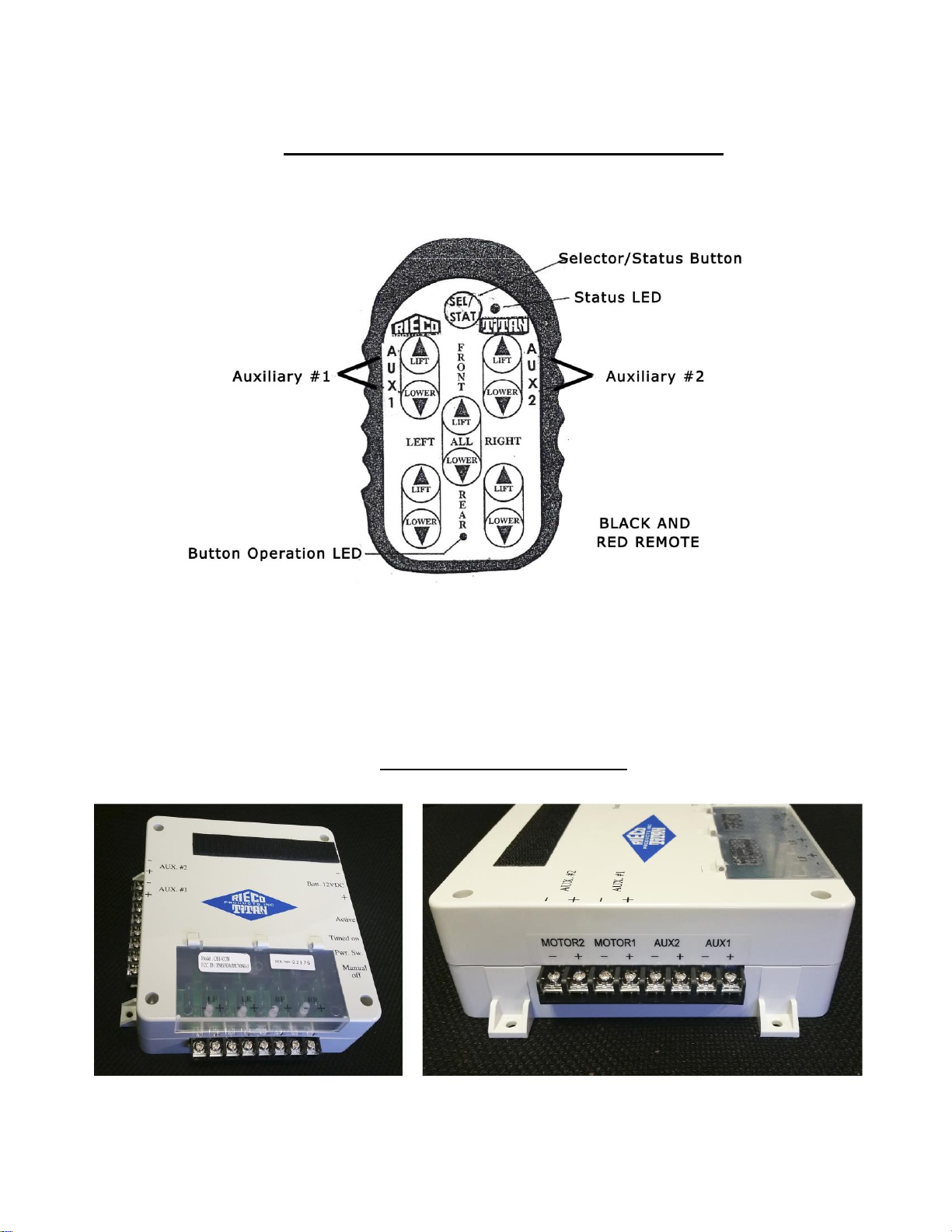
Mode Selection: To select the controls for either the four jacks or the two auxiliary
devices, we provided a Selector/Status button on the face of the remote (incorporated
into the button membrane) for changing from four circuits to two circuits, and viceversa. The operator presses the Selector/Status button for five seconds, and an LED will
indicate bright red for the four jack mode and green for the two auxiliary device
mode.
Confirmation: For confirmation of the mode of control at any time, the operator
presses the Selector/Status button once quickly and the LED will indicate the mode
that the system is in.
This method of mode selection also eliminates the concern about draining the battery
in the remote.
Operation: The top four buttons on the remote will operate the two auxiliary devices.
The bottom four buttons and the “All” buttons will be inoperative during the Auxiliary
mode.
In the four Jack mode, the buttons will all function as our normal button controls, with
all buttons active. Labels are provided on the face of the remote to indicate which
buttons control auxiliary devices and which control jacks. The red remote will be set
up identically.
Rieco-Titan Products, Inc Rev. 03/06/13
-2-
REMOTE CONTROL BUTTON ARRANGEMENT
The Receiver Control Box for the six circuit system is accommodated by utilizing the
cube within the case to house the four extra relays, fuses and terminals. Appropriate
labeling is provided to indicate component designations as on our present unit.
RECEIVER CONROL BOX
Rieco-Titan Products, Inc Rev. 03/06/13
 Loading...