

Page 1
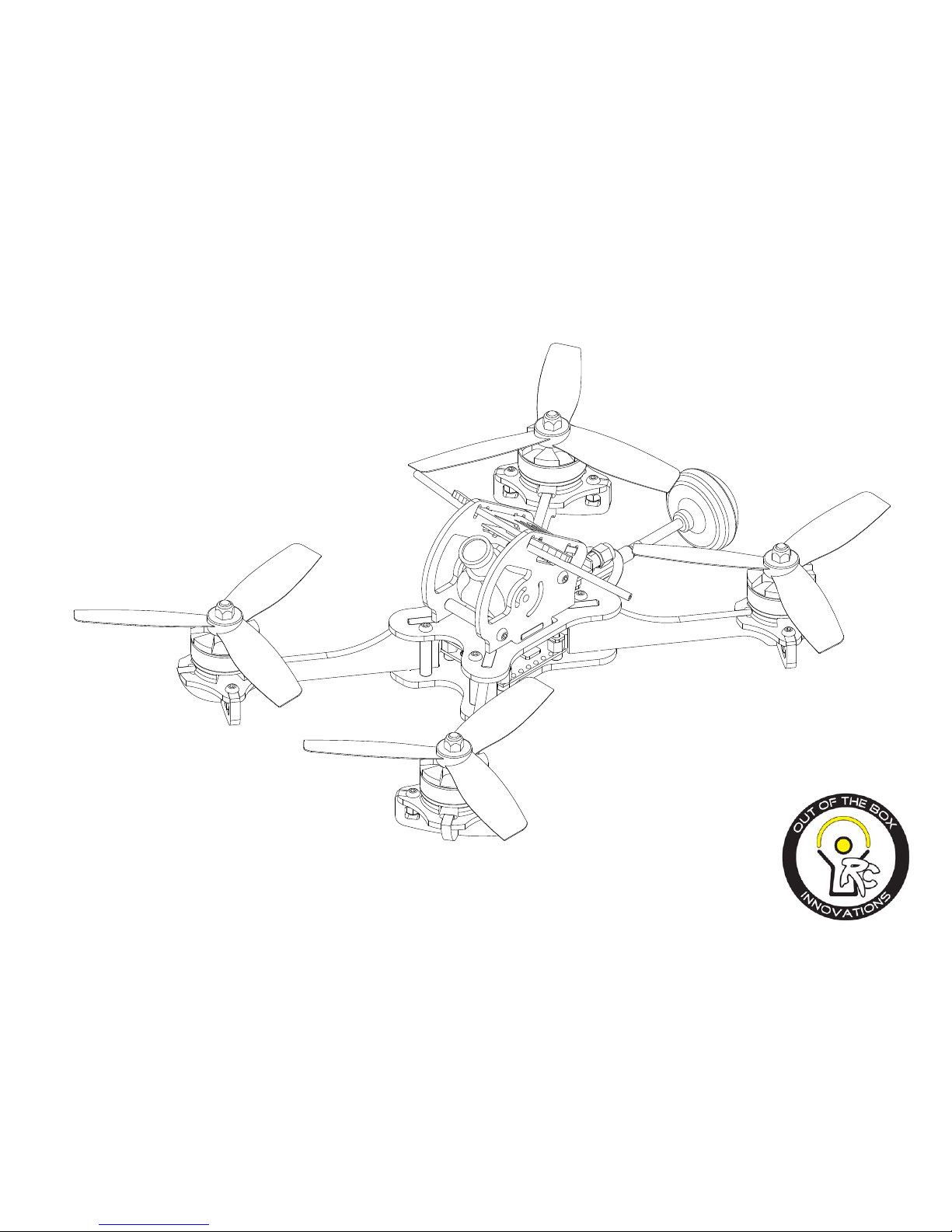
VLS230
Assembly manual
Patent Pending
V1.020170723
Page 2

THANK YOU!
Welcome and thank you for purchasing the VLS230. I know you are looking forward to ying an
advanced racing drone that can be customized and can deliver ecient air ow, a strong frame, and
fantastic ying capabilities. In this manual you will nd the instructions that will take you step by step
to complete your drone and to start ying!
As you are working through the instructions it is important that you READ THE DIRECTIONS! There
are ne points covered that you will miss if you only assemble by the pictures. You will enjoy your
journey much more if you follow the instructions provided in this manual.
As always, we are dedicated to your drone ying experience and if you have thoughts, suggestions,
concerns, or want to share a happy ight, please feel free to contact us!
DISCLAIMER:
Out of the Box Innovations RC can not foresee the equipment you will purchase or how you will use
the product when you receive it. We are not responsible for any injuries or property damage to anyone or anything as it relates to this product. USE AT YOUR OWN RISK!
Page 3
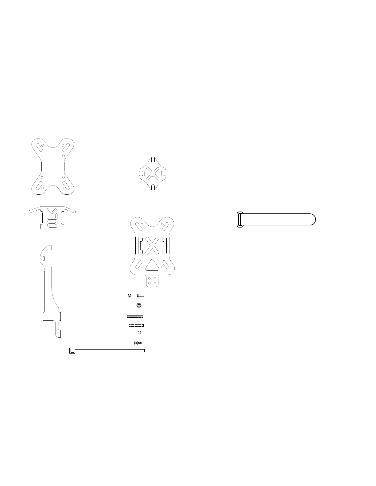
Please go over this list below. Verify that all objects on this list are
accounted for before building your quad-copter.
Cinch Strap Qt x1
Zip Ties
20
25
28
34
14
15
20
25
28
5
1.5
.75
8
6
34
4
5
6
7
8
7
8
A A
B B
C C
D D
2
3
4
5
6
1
2
3
4
5
3
4
5
6
7
5
6
7
8
D D
.75
4
3
3
2
6
7
8
D D
4
3
3
2
3
4
5
6
7
8
14
15
20
25
28
40
5
1.5
.75
8
6
4
3
3
34
2
3
4
5
6
7
4
6
7
8
4
3
3
2
7
8
4
3
3
2
M3 x 10 Screw
M3 Lock Nut
x 24
x 8
x 2
x 4
x 4
x 4
x 2
Bottom Plate
X 1
Top
Plate
X 1
A-Cam
Plate
X 1
Limb
Plate
X 4
Motor Mount
Plate
X 4
28mm Stando
20mm Stando
3mm Stando
5mm Nylon Stando
Page 4
Solder
With Flux
Wire Clippers
Blue
Loctite
Solder
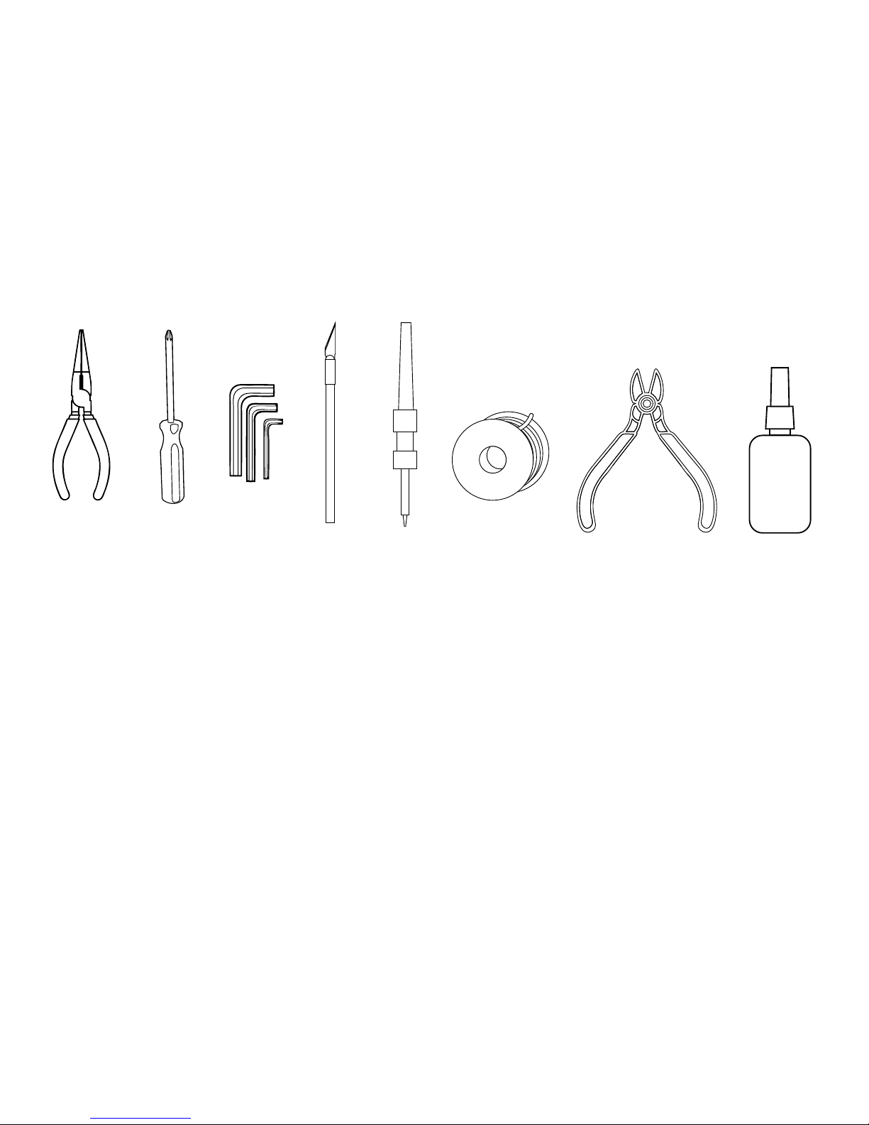
Tools and hardware we recommend
Needle
Nosed
Pliers
PhillipsHead Screw
Drivers
Allen
Wrench
Set- Metric
Hobby
Knife
Soldering
Iron
Solder
Page 5

Contents
Bottom Plate Assembly 1
ESC and FC assembly 2
Motor and Limb Assembly 3
FITTING LIMBS 4
Main Body Assembly 5
VTX and Antenna Assembly 6
Pod Assembly 7
Antenna Option 8
Propeller Assembly 9
Ready to Fly 10
Page 6
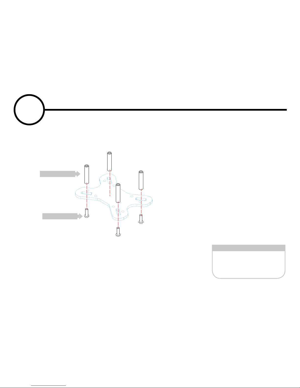
What you need for this step
Using M3 screws, secure the
20mm standoff to the main
plate.
M3 x 10 Screw
20 MM Standoff
x 4
x 4
20mm Standoff
M3 x 10 Screw
1
Bottom Plate Assembly
Page 7
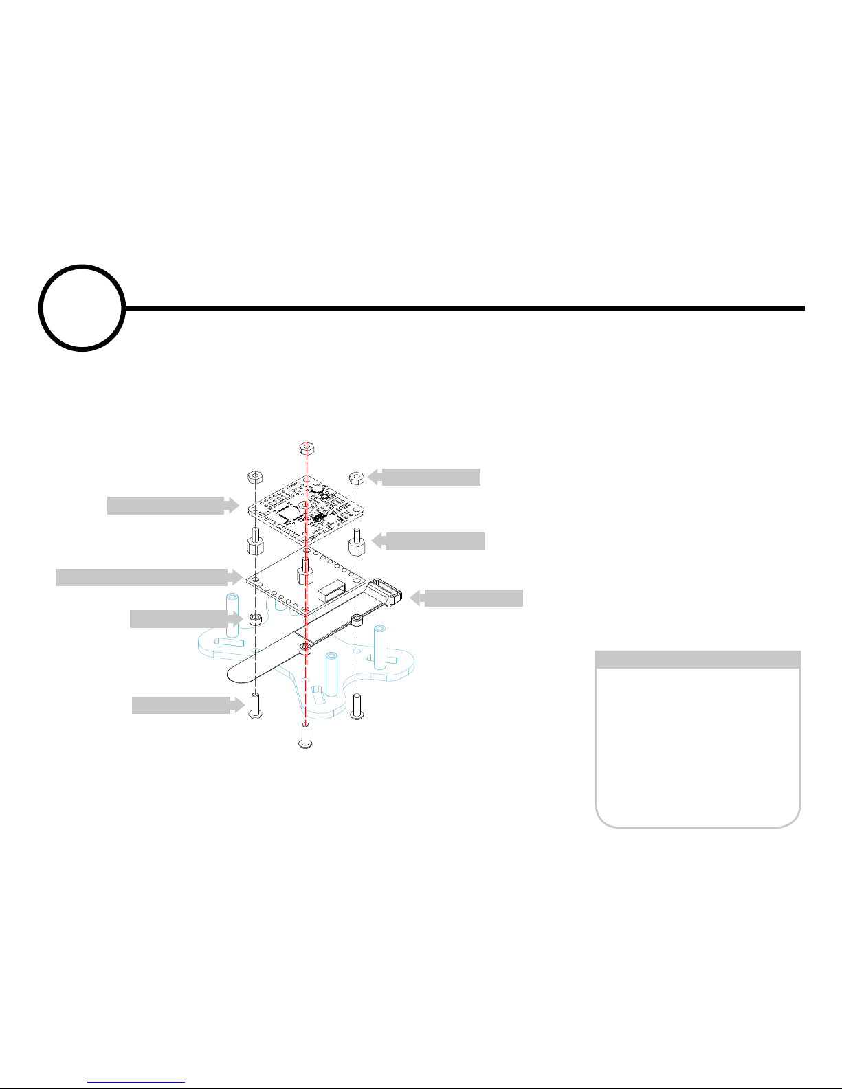
What you need for this step
Depending on the Electronic
speed control (ESC) that you
use, you might have to mount
the individual ESC to the
limbs of the VLS. However,
for this build we are using
a 4-in-1 ESC which we will
mount to the bottom plate
using the 3mm standoffs and
M3 x 10 screws. Mount the
Flight controller (FC) above
the ESC using the 6mm standoffs and secure with the M3
nylon nuts. You can also slip
the battery strap just below
the ESC.
M3 x 10 Screw
5 MM Standoff
3 MM Standoff
ESC (4 in 1)
FC
Nylon Nuts
Battery Strap
x 4
x 4
x4
x 1
x 1
x 4
x1
Flight Controller (FC)
Electronic Speed Controller (ESC)
5mm Standoff
Battery Strap
Nylon Nut
M3 x 10 Screw
M3 x 3 Standoff
2
ESC and FC assembly
Page 8
6
7
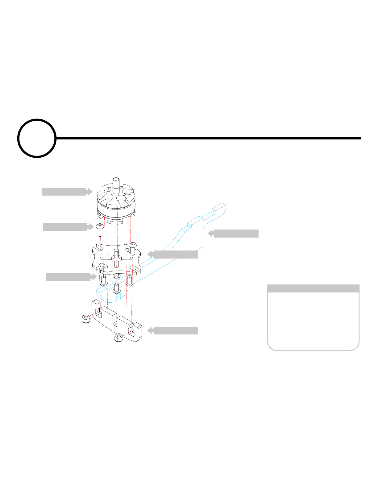
What you need for this step
Using supplied screws from
your vendor attach your
brushless motor to a motor
mount plate.
Slide the retention plate below
the motor plate and secure to
the limb with 2, M3x10 screws
and lock nuts.
M3 x 10 Screw
M3 x 6 *or supplied
hardware
15 mm Standoff
Motor Mount Plate
x 16
x 8
x 8
3
Motor and Limb Assembly
Brushless Motor
M3 x 6 Screw
M3 x 10 Screw
Motor Mount
Retention Plate
Limb Plate
Page 9
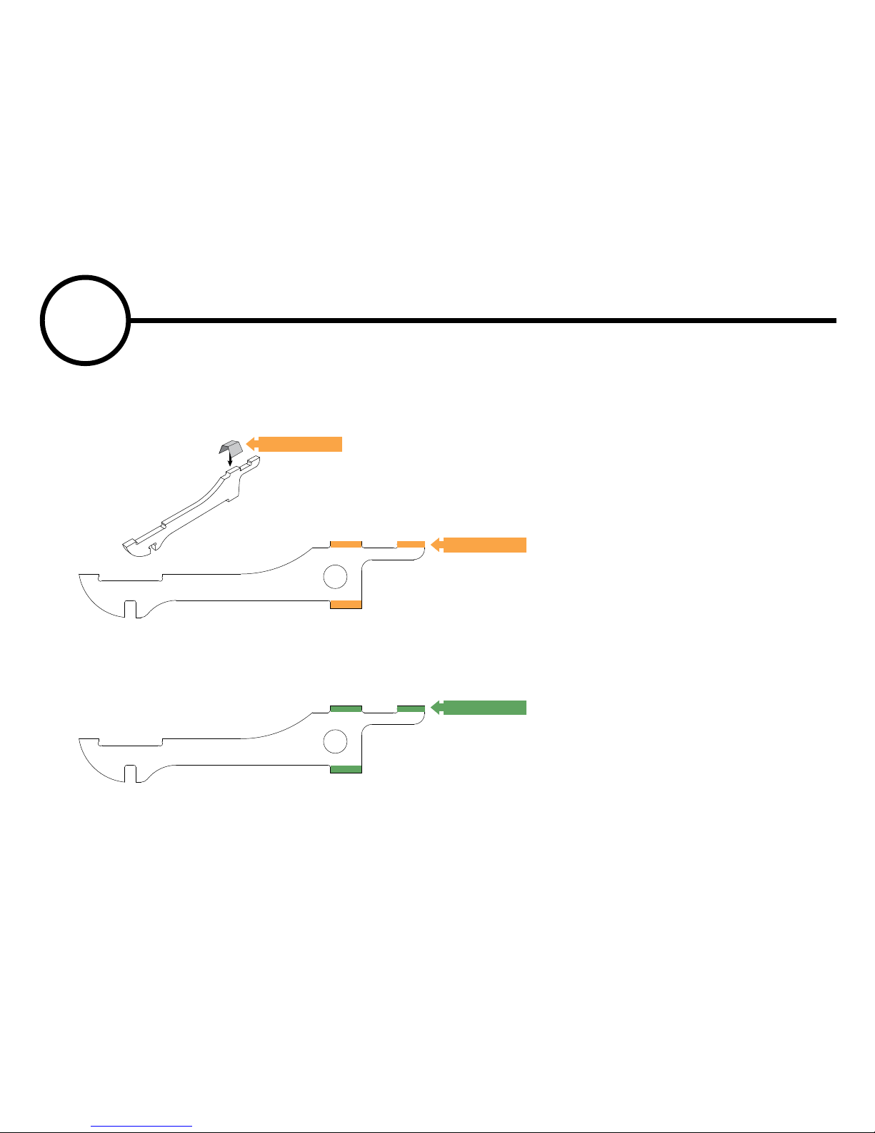
Loose limbs, from either crashing or tiny irregularities in the production of the materials, can be
felt by gently wiggling your arms from time to time to verify a solid frame. If you find you have a
tiny bit of wiggle, there is a simple solution.
4
FITTING LIMBS
4
5
6
7
4
5
6
7
Tape
Sand
Tape
If a limb is “loose” a small
amount of electrical tape (or
whatever tape that is paper
thin) placed around the tops of
the tabs of the limb and then
the top plate locks it in place
when it’s all re-assembled takes
away the gap and results in a
solid frame once again.
If a limb is “tight” (as in, can’t
get the limb through the slot) a
small amount of sanding across
just the tabs should fix it.
Loose fit
Tight fit
Page 10
5
6
7
8
What you need for this step
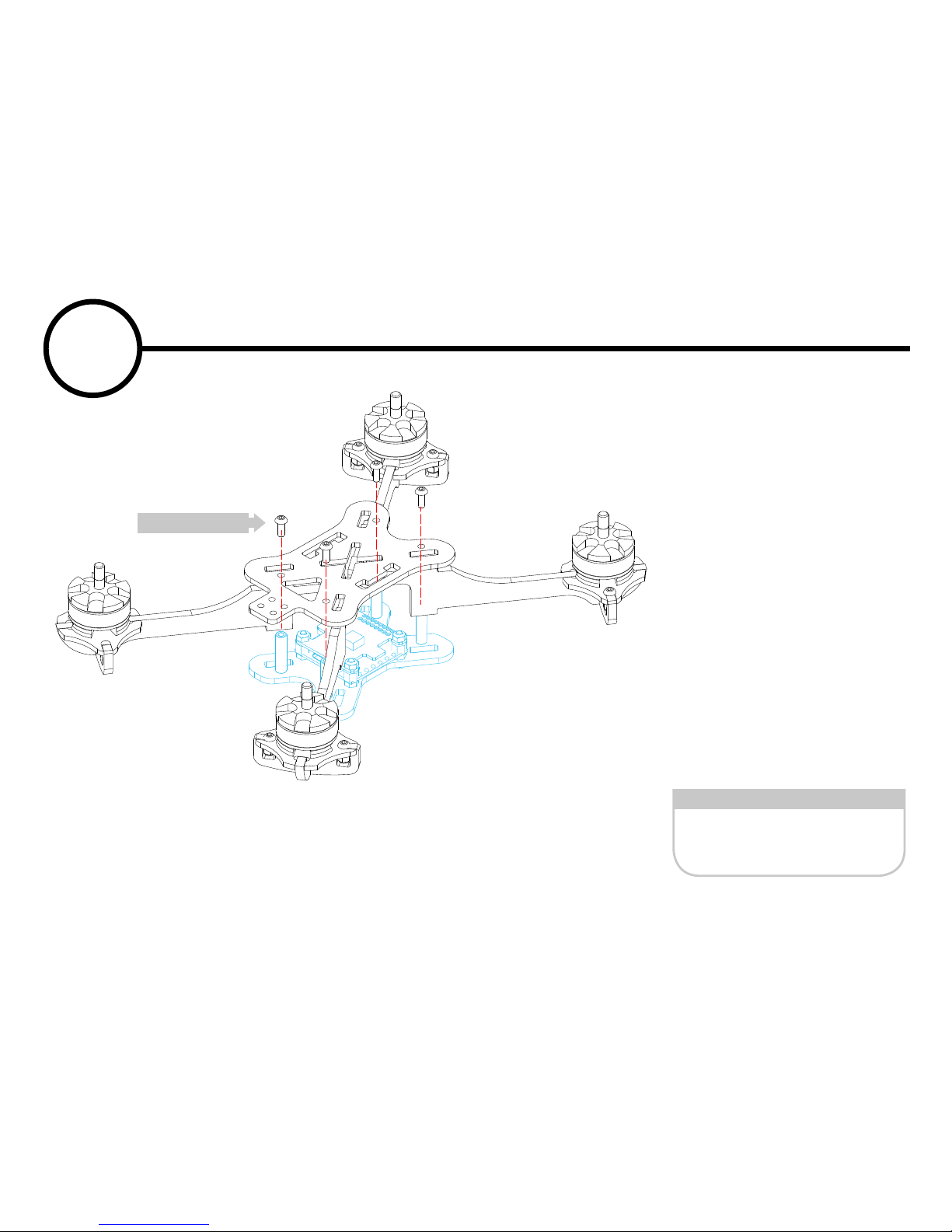
Now you can finish assembly
of the main body with M3 x
10 screws while aligning your
limbs into the slots located
on both the top and bottom
plates as shown. It can help to
carefully test-fit the limbs first
to ensure proper fit. Some
light sanding may be necessary but it should be a tight fit
so be patient with this step.
Be careful to note the direction of the ESC and the FC!
Be sure they are all aligned
correctly!
M3 x 10 Screw x 4
5
Main Body Assembly
M3 x 10 Screw
WARNING:
Do not use standoff screws to force the top or bottom plates on to the limb.
The limbs should fit very snug but, press on the plates with fingers and
secure with screws.
Page 11
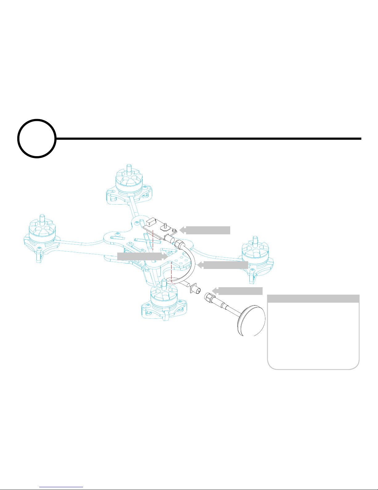
What you need for this step
Attach the VTX to the upper
plate with double sided sticky
tape.
Using a remote cable, connect
the VTX to the VTX antenna
and then secure to the upper
plate with 2 zip-ties.
VTX
Remote Cable
VTX Antenna
Zip Ties
x 1
x 1
x 1
x 2
5
6
7
8
Zip Tie Holes
6
VTX and Antenna Assembly
VTX
Antenna
Remote Cable
Page 12
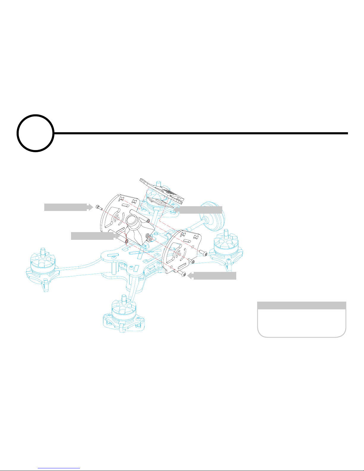
What you need for this step
Attach the upper pod portion
to the top plate with by sliding
the side plates onto the tabs
located in the top plate of the
main body. Secure your FPV
camera with 2mm screws to
one side. Attach the RX to
the Cam Plate. Slide the Cam
Plate through the holes of the
side plates and carefully feed
the antenna through the holes
as well. Secure the second
side plate with M3 x 10 screws
and the M2 screw for the
other side of the camera.
M3 x 10 Screw
M3 Lock nut
x 4
x 4
5
6
7
8
FPV Camera
M2 Screw
Receiver
M3 Screw
7
Pod Assembly
Page 13
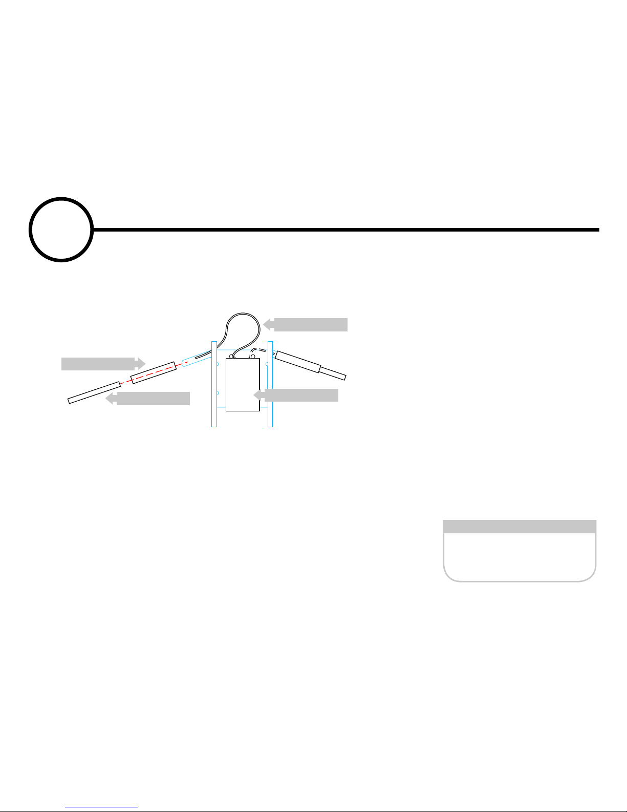
What you need for this step
The antenna can be protected
using plastic tubing held in
place with heat-shrink tubing
(1/4” should suffice). Finish
with end caps for the tubes.
Heat Shrink Tubing
Plastic Tubing
x 4
x 4
Heat Shrink Tubing
Plastic tubing
Receiver
Antenna
8
Antenna Option
Page 14
4
5
6
7
8
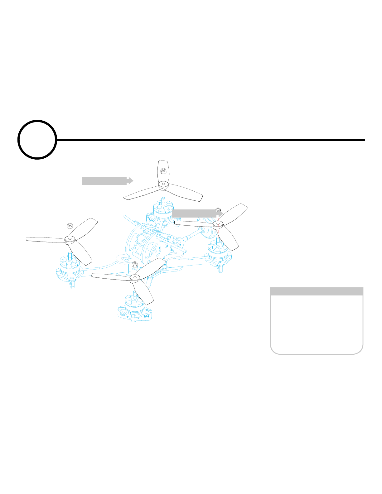
What you need for this step
After verifying your motor rotation via your flight
controller instructions. It is
highly recommended that you
secure your racing propellers
to your motors with lock-nuts.
Lock nuts are prerable. Prop
nuts may fly off during flight
causing damage to your quadcopter.
WARNING: NEVER test
your motors with the propellers on. Physical harm may
occur.
5” or 6” propeller
Lock nut
x 4
x 4
9
Propeller Assembly
Propeller
Lock nut
Page 15
4
5
6
7
8
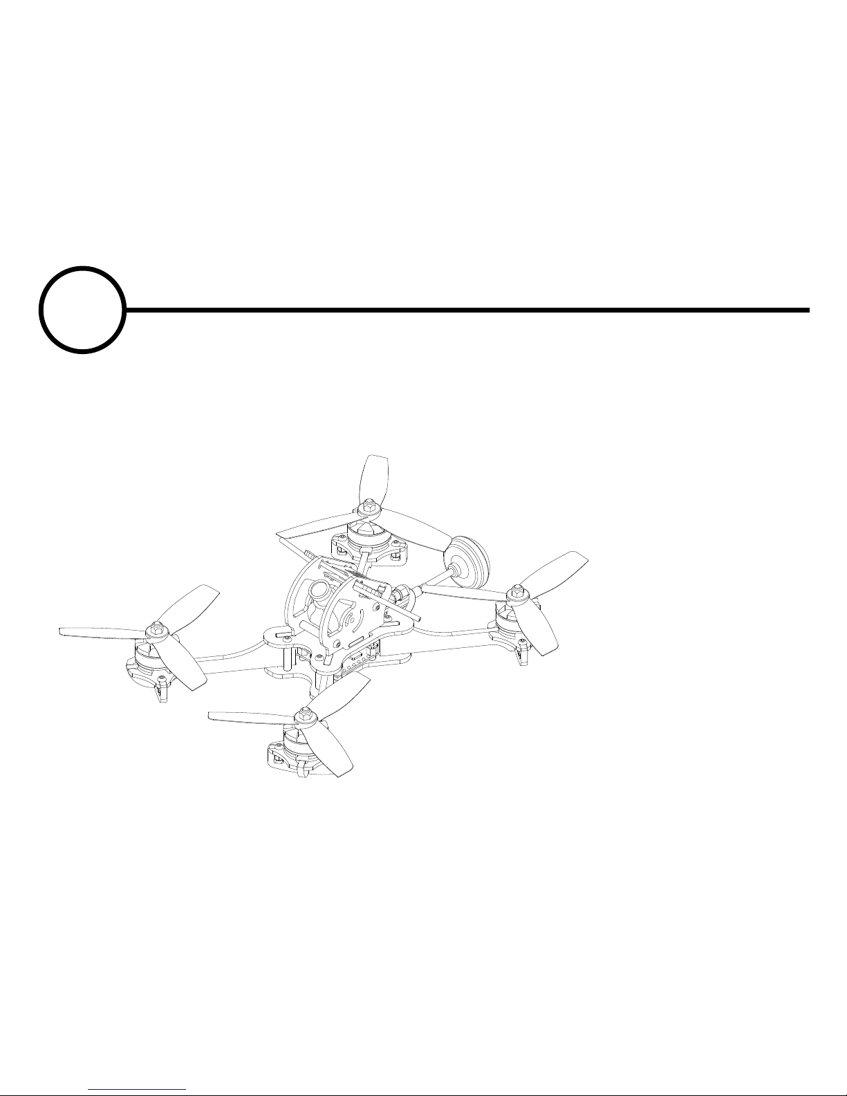
Now you’ve completed your
build. Be sure to research
your particular equipment
and be sure it is 100% operational before attempting to fly.
WARNING: NEVER test
your motors with the propellers on.
10
Ready to Fly
Page 16

NOTES:
 Loading...