

Page 1
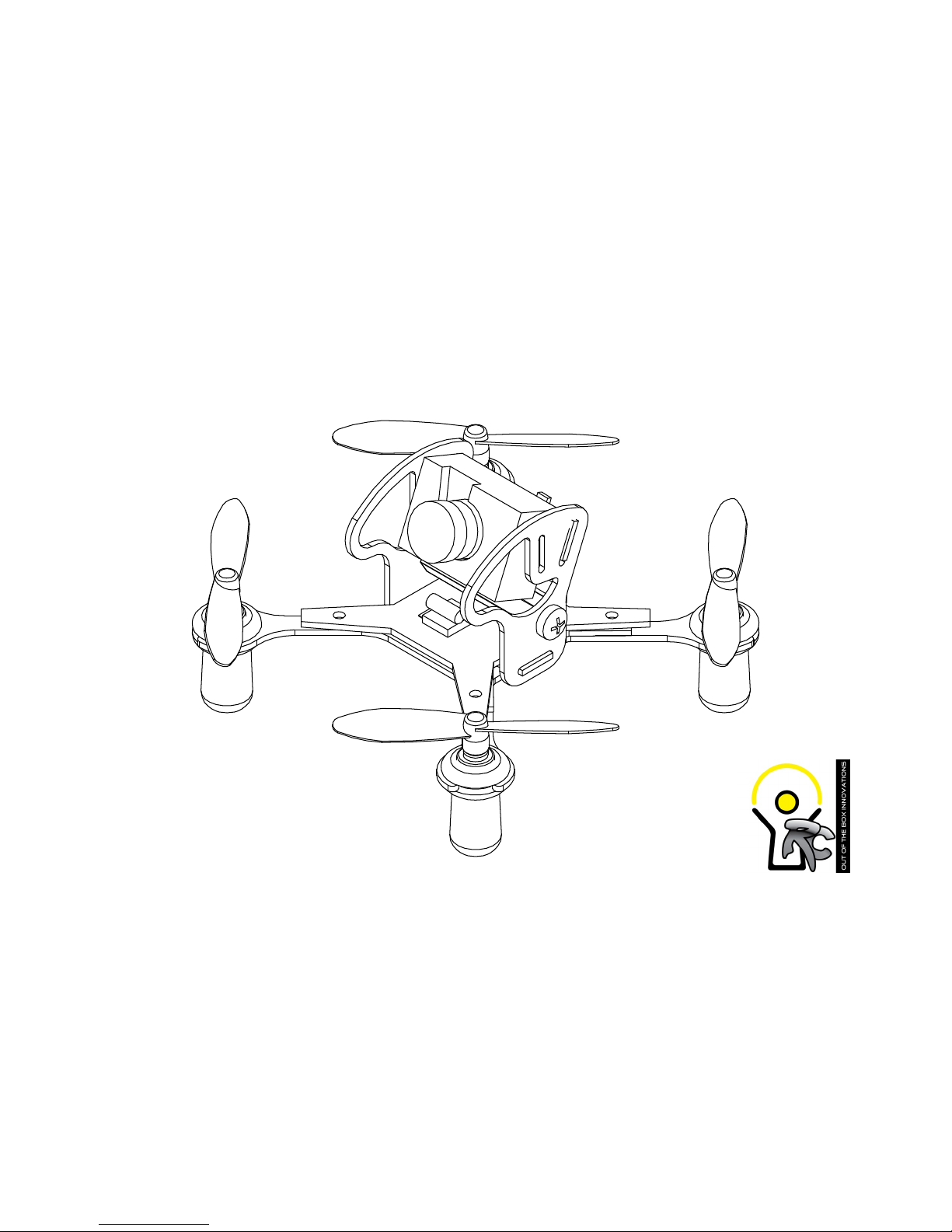
H8CF101
Assembly manual
V1.20161004
Page 2

Welcome and thank you for purchasing the H8CF101 conversion kit. I know you are looking forward
to ying an advanced racing drone that can be customized and can deliver ecient air ow, a strong
frame, and fantastic ying capabilities. In this manual you will nd the instructions that will take you
step by step to comple your drone and to start ying!
As you are working through the instructions it is important that you READ THE DIRECTIONS! There
are ne points covered that you will miss if you only assemble by the pictures. You will enjoy your
journey much more if you follow the instructions provided in this manual.
As always, we are dedicated to your drone ying experience and if you have thoughts, suggestions,
concerns, or want to share a happy ight, please feel free to contact us!
DISCLAIMER:
Out of the Box Innovations RC can not forsee the equipment you will purchase or how you will use
the product when you recieve it. We are not responsible for any injuries or property damage to anyone or anything as it relates to this product. USE AT YOUR OWN RISK!
Page 3
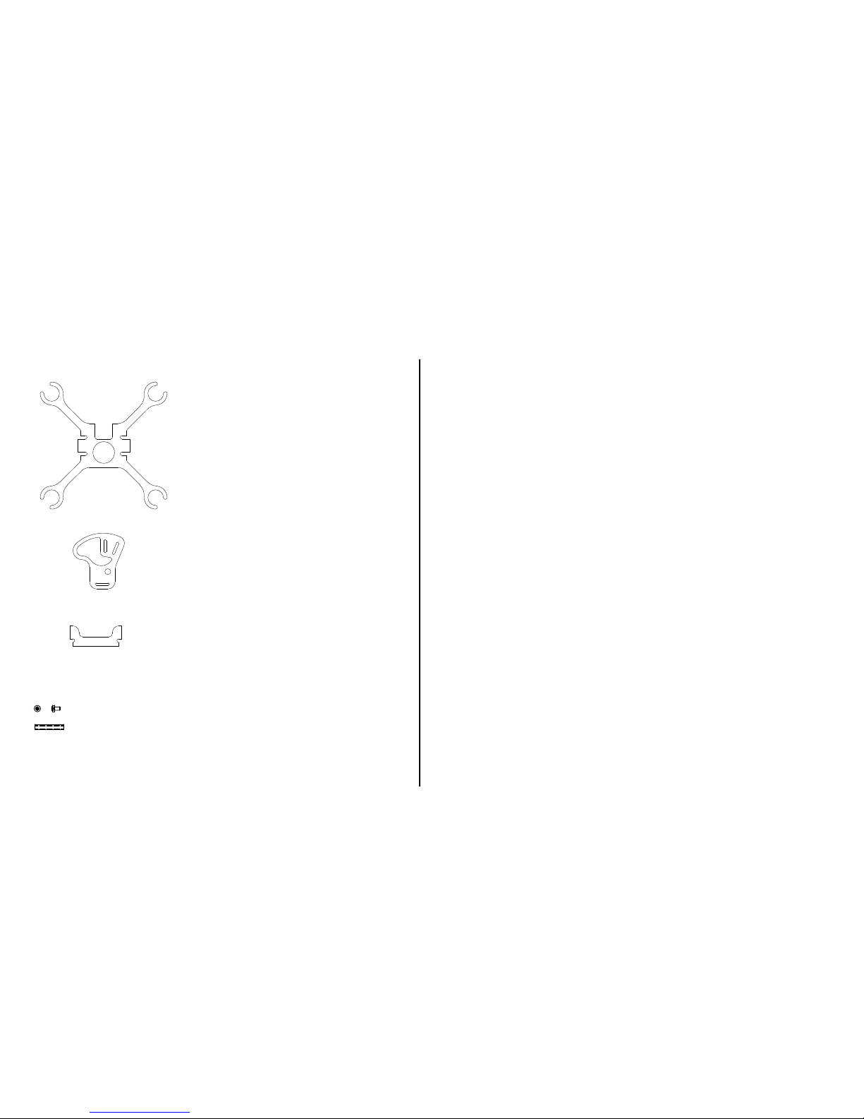
Please go over this list below. Verify that all
objects on this list are accounted for before
building your quad-copter.
You will need these items to y your kit.
Eachine H8 or equivalent quad-copter.
8.5mm brushed motors x4
55mm-65mm propellers for the motors x4
(though extras are always recommended)
For FPV ight
Micro Camera with Built in VTX
FX798T Recommended
PICO male connector with small wire attached.
Battery Lipo 500mAh 25C rating or better.
Small philips head screwdriver
Soldering iron
Double Sided Sticky Tape
6
7
8
D D
4
3
3
2
2
3
4
5
6
7
8
14
15
20
25
28
40
5
1.5
.75
8
6
4
3
3
34
M3 x 6 nylon screw
25mm Stando
Rubber Band
Rubber Caps
x 2
x 1
x 1
x 4
Main Plate
X 1
Side Plate
X 2
Camera Plate
X 1
1
2
3
4
5
1
2
3
4
5
2
3
4
5
Page 4
What you need for this step
What you need for this step
What you need for this step
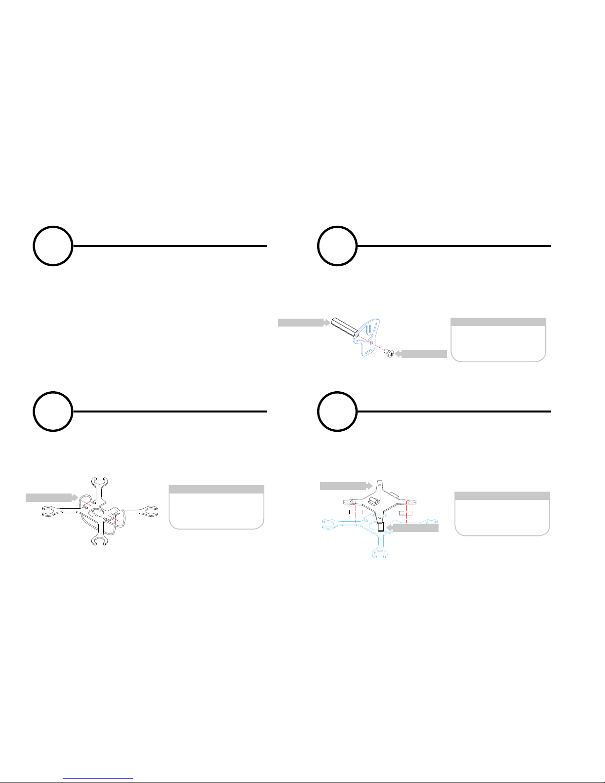
Remove the screws from under the H8 frame. Gently remove the top and de-solder the motors from the PCB.
Gently remove the PCB from the quad-copter.
Solder your power tail from the male PICO connector to
your PCB at the point where the battery connects to the
PCB. Be sure to solder positive to positive and negative to
negative. Reversing these may damage your FPV camera.
If you are going to flash your H8 to make it ACRO, then
you’ll also want to attach your flash leads at this time. Use
as small a connector as possible to keep your weight to a
minimum if you’re going to leave it on the board.
Attach the 25mm standoff to the side plate as shown with
1 nylon screw.
Stretch the rubber band between the slots on the side
of the main frame. The battery will be held in place between it and the frame underneath.
Cut small pieces of double sided tape to hold the PCB
in place on the frame. Make sure the battery connector
fits into the slot as shown. Be sure your PCB is relatively
straight on the frame..
1 2
3 4
PCB Preperation Side Plate Assembly
Battery Strap Assembly PCB Assembly
M3 x 6 nylon
screw
25 MM Standoff
Rubber Band
PCB
Double Sided
Stick Tape
x 1
x 1
x 1
x 1
4
5
6
7
8
4
5
6
7
8
4
5
6
7
8
25mm Standoff
Rubber Band
PCB
M3 x 6 Screw
Double Sided Tape
Page 5
4
5
6
7
8
What you need for this step
What you need for this step
What you need for this step
What you need for this step
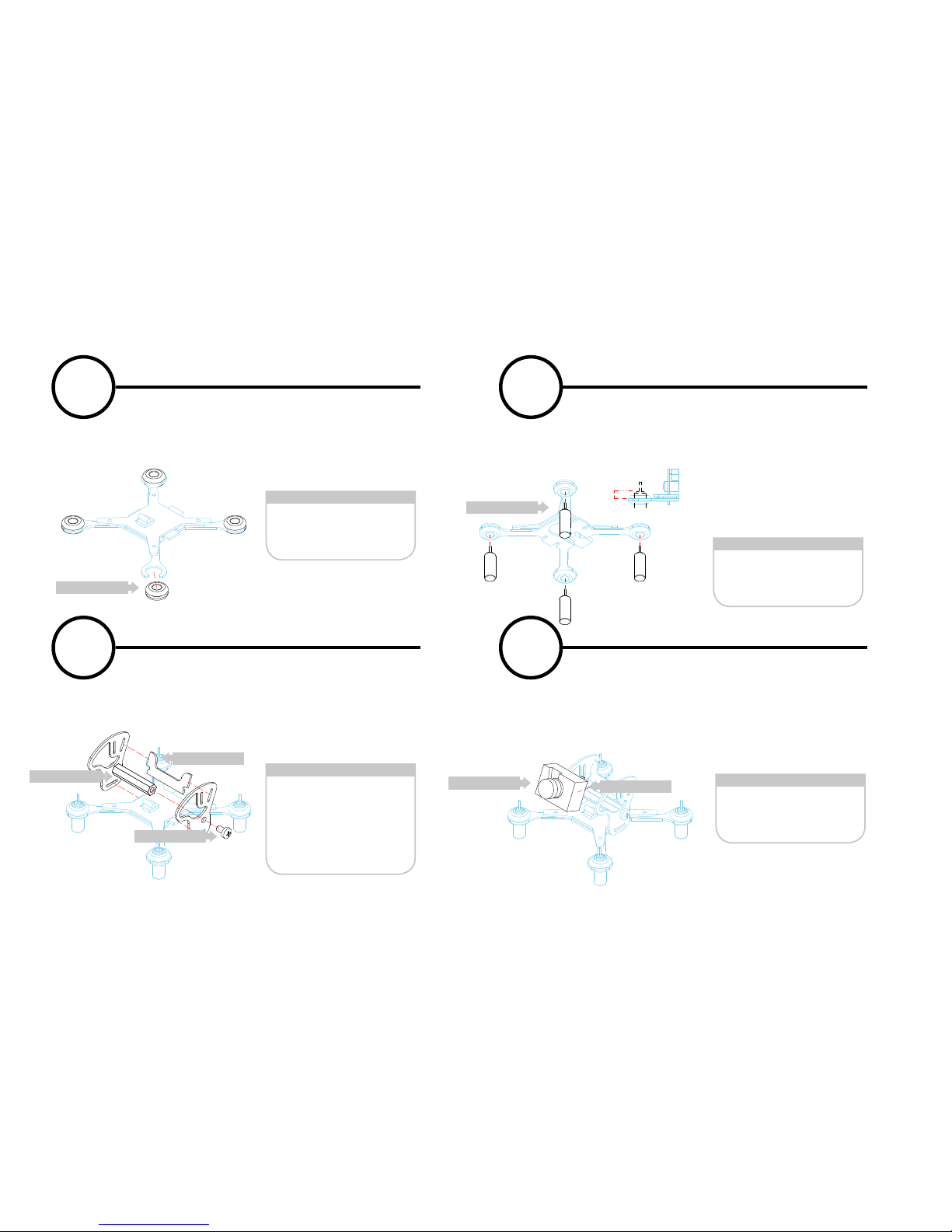
Assemble your side plates using the attached 25mm
standoff and nylon screw. Be sure to secure the camera
plate between the side plates. Be cautios of the rubber
band and try not to pinch it with the side plates.
Gently pinch the rubber grommet and insert into the
groove at the end of each limb. Release the gromment
and gently adjust any material until it rests in the groove.
A little soapy water can make this part much easier.
Put a tiny bit of soapy water on the bottom of each grommet. Gently press the motors until they slide into place
inside the grommet. Adjust the heigh until the top of the
motor is about 5mm from the top of the frame.
Re-connect your motors to the
PCB and verify motor rotation.
Be sure to leave a little slack in the
wires for the protectors.
Mount your FPV camera using a small piece of double
sided sticky tape and secure to the camera plate as
shown. You can adjust from 0 degrees to 20 degrees
angle on your camera by using the correct slots on the
side plates.
5 6
7 8
PCB Preperation Motor Assembly
Pod Assembly FPV Camera Assembly
Side Plates
25mm Standoff
M3 x 6 nylon
screw
Camera Plate
Rubber Grommet
8.5mm Motors
FPV Camera
Double Sided
Stick Tape
x 1
x 1
x 1
x 1
x 4
x 4
x 1
3
4
5
6
4
5
6
7
8
5mm
3
4
5
6
FPV Camera
Double Sided Tape
25mm Standoff
Rubber Grommet
8.5 Brushed Motor
M3 x 6 nylon screw
Cam Plate
Page 6
What you need for this step
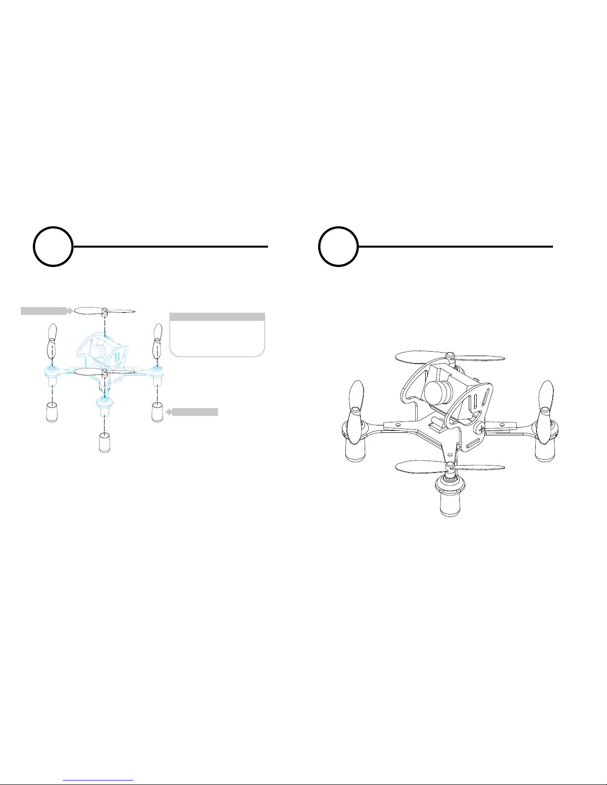
Gently press on your new 55mm-65mm propellers onto
the motors verifying the direction of the props.
Gently press on the rubber caps to the underside of the
motors which will help protect the motors and
wire connections.
Now you’ve completed your build. Be sure to research
your particular equipment and be sure it is 100% operational before attempting to fly.
WARNING: NEVER test your motors with the propel-
lers on.
9
10
PCB Preperation Ready to fly
55mm - 65mm Propellers
Ruber Caps
x 4
x 4
3
4
5
6
Propeller
Rubber Cap
 Loading...