

Page 1

MANUALE DI ISTRUZIONI
OPERATING MANUAL
T4 - T44
AMPLIFICATORE DI POTENZA
POWER AMPLIFIER
PROFESSIONAL AUDIO
Page 2
Outline è costantemente impegnata in ricerche mirate al
continuo miglioramento dei propri prodotti. Per questo motivo,
nuove tecnologie, materiali e metodi di produzione, vengono
continuamente incorporati nei prodotti esistenti quale
espressione della nostra filosofia costruttiva. Per questa
ragione qualsiasi prodotto Outline potrà lievemente differire
dalla sua descrizione qui pubblicata, ma comunque uguaglierà
o supererà le caratteristiche qui specificate.
© Outline 2004
Manuale d’istruzioni n. ItaEng/TSA
Stampato in Italia
Aggiornato al settembre 2004
Outline continually engages in research related to
product improvement. New materials, new production
methods and design refinements are introduced into
existing products without notice as a routine expression
of our philosophy. For this reason, any current Outline
product may differ in some aspect from its description,
but will always be equal or exceed the original design
specifications unless otherwise stated.
© Outline 2004
Operating manual product Nr. ItaEng/TSA
Printed in Italy
Revised September 2004
PRECAUZIONI DI SICUREZZA
Affidate l’assistenza a personale qualificato, attraverso il
vostro rivenditore Outline.
DISCONNETTERE SEMPRE L’AMPLIFICATORE DALLA RETE
MENTRE SI LAVORA AL SUO INTERNO.
SAFETY PRECAUTIONS
Refer all servicing to qualified personnel, through your
Outline dealer.
ALWAYS DISCONNECT POWER AMPLIFIER FROM
MAINS WHILE WORKING INSIDE.
* COMFORMITÀ
*Comunità Europea
Tutte le apparecchiature elettroniche ed elettroacustiche
Outline rispondono ai requisiti indicati dalle direttive CEE :
Sicurezza - 73/23 e successiva modificazione 93/68 art. 13
Compatibilità elettromagnetica - 89/336 e successiva
modificazione 93/68 Art. 5.
Gli standard applicati sono :
Sicurezza : EN 60065
Prescrizioni di sicurezza per apparecchi elettronici e loro
accessori collegati alla rete per uso domestico e analogo uso
generale.
Compatibilità elettromagnetica per apparecchiature audio
Emissioni - Armoniche : EN 61000-3-2
- Fluttuazioni di tensione : EN 61000-3-3
- Interferenze radio : EN 55013
Immunità : EN 55020
• COMFORMITY
• *European Community
All the Outline electroacoustic and electronic devices are
in accordance with the objects stated by below CEE
directives :
Safety - 73/23 and following modification 93/68 Art. 13
Electromagnetic compatibility - 89/336 and following
modification 93/68 Art. 5
Standards applied :
Safety : EN 60065
Safety requirements for mains operated electronic and
related apparatus for household and similar general use.
Electromagnetic compatibility for audio equipments
Emissions - Harmonics : EN 61000-3-2
- Voltage fluctuations : EN 61000-3-3
- Radio interference : EN 55013
Immunity : EN 55020
Page 3

T series power amplifiers professional audio page 1
T4 – T44
outline s.n.c. di noselli g. & c. - v. leonardo da vinci, 56 - 25020 flero (bs) - italy - tel. +39-30-3581341 fax +39-30-3580431
Web Site: http://www.outline.it E-Mail : info@outline.it
82
READY
PROT
100
LEVEL
1 9
SIGNAL
25%
5
73
4 6
82
TEMP
PROT
100
LEVEL
1 9
SIGNAL
5
73
64
25%
READYTEMP
75%
100%
CLIP
CH1
50%
2
1
3
2 88
LEVEL
CH1/CH2
PROTECT
9
0 1091010
SIGNAL
25%
7
4 656734
5
CLIP
75%
100%
CH1 CH2
READYTEMP
50%50%
100%
75%
CH2 CLIP
50%
8282
LEVEL
CH3/CH4
PROTECT
901
1091010
25%
SIGNAL
743
5
6 6734
5
CLIP
75%
100%
CH3 CH4
Page 4

T series power amplifiers professional audio page 2
INTRODUZIONE / INTRODUCTION
Le esigenze di facile trasportabilità e quindi di pesi contenuti,
unite a grandi potenze, sono oggi sintetizzate nei nuovi
amplificatori di potenza Outline Serie T che adottano la
tecnologia DIGAM® con uno stadio finale totalmente a
commutazione.
Le innovazioni tecnologiche utilizzate, coperte da brevetto,
permettono di sfruttare appieno le doti di efficienza, robustezza,
rendimento ed economicità dei sistemi PWM, conservando ed
esaltando al contempo le doti di musicalità dei migliori sistemi
analogici. L’utilizzo di una frequenza di campionamento di 250
KHz, di uno stadio finale ad elevatissima corrente di
polarizzazione e l’adozione innovativi sistemi di conversione D/A
di potenza, sono alcune delle soluzioni mirate alla
massimizzazione delle prestazioni in banda audio, raggiungendo
risultati allo stato dell’arte.
L’utilizzo della tecnica di conversione PWM (Pulse Width
Modulation), permette di ottenere prestazioni imbattibili dal punto
di vista della DENSITÀ di POTENZA e dell’ EFFICIENZA in
confronto con i convenzionali amplificatori lineari. I risultati
ottenuti permettono agli amplificatori della Serie T Outline di
essere più piccoli e circa 5 volte inferiori come peso rispetto agli
amplificatori tradizionali della stessa potenza, consentendo quindi
una facile trasportabilità e riducendo lo spazio occupato nei rack.
Inoltre, l’altissimo rendimento della Serie T Outline (superiore al
90%) permette di ottenere, con programmi musicali standard,
una riduzione a circa 1/10 della potenza dissipata rispetto ad un
equivalente amplificatore lineare.
Il circuito di conversione in alta frequenza adottato negli
amplificatori della Serie T Outline, diversamente da alcuni
amplificatori commerciali che utilizzano convertitori switching
AC/DC "off-line", simula virtualmente un carico puramente
resistivo realizzando una correzione del fattore di potenza e
permettendo di ottenere una stabilizzazione pressoché totale
della tensione di alimentazione dello stadio finale,
indipendentemente dalla tensione di rete, mantenendo così
inalterate le prestazioni del finale e minimizzando quindi la
potenza reattiva e la distorsione armonica introdotta sulla
corrente assorbita.
The need for easy portability, and therefore low weight combined
with high power, is now met with the new Outline Series T power
amps, which use DIGAM® technology with a completely
switching output stage.
The patented technical innovations used enable to exploit to the
utmost the merits of efficiency, sturdiness, yield and reduced
costs of PWM systems, maintaining and at the same time
enhancing the musical qualities of the best analogue systems.
The use of a sampling frequency of 250 KHz, an output stage
with an extremely high polarization current and innovative D/A
power conversion systems are some of the solutions aimed at
optimizing audio band performance, achieving state of the art
results.
The use of PWM (Pulse Width Modulation) conversion
techniques enables unbeatable performance to be achieved from
the point of view of POWER DENSITY and EFFICIENCY,
compared to conventional linear amplifiers. The results achieved
enable the Series T amplifiers to be smaller and about a fifth of
the weight of traditional amplifiers of the same power, thus greatly
facilitating transport and reducing rack space required. Moreover,
with standard music programs, the Outline T Series’ very high
yield (over 90%) enables to reduce dissipated power to about
1/10 that of an equivalent linear amplifier
The results achieved enable the Series T amplifiers to be smaller
and about a fifth of the weight of traditional amplifiers of the same
power, thus greatly facilitating transport and reducing rack space
requirements.
As opposed to some commercial amplifiers that use AC/DC "offline" switching converters, the HF conversion circuit used in the
Outline Series T amplifiers virtually simulates a purely resistive
load carrying out power factor correction and ensuring almost
total stabilization of the power voltage of the output stage, no
matter what the mains voltage. This keeps the power amplifier’s
performance unchanged, thus minimizing reactive power and
harmonic distortion introduced on the current absorbed.
outline s.n.c. di noselli g. & c. - v. leonardo da vinci, 56 - 25020 flero (bs) - italy - tel. +39-30-3581341 fax +39-30-3580431
Web Site: http://www.outline.it E-Mail : info@outline.it
Page 5
231
HOT
COLD
GND
(a)
HOT GND
COLD
3
2 1
(b)
T series power amplifiers professional audio page 3
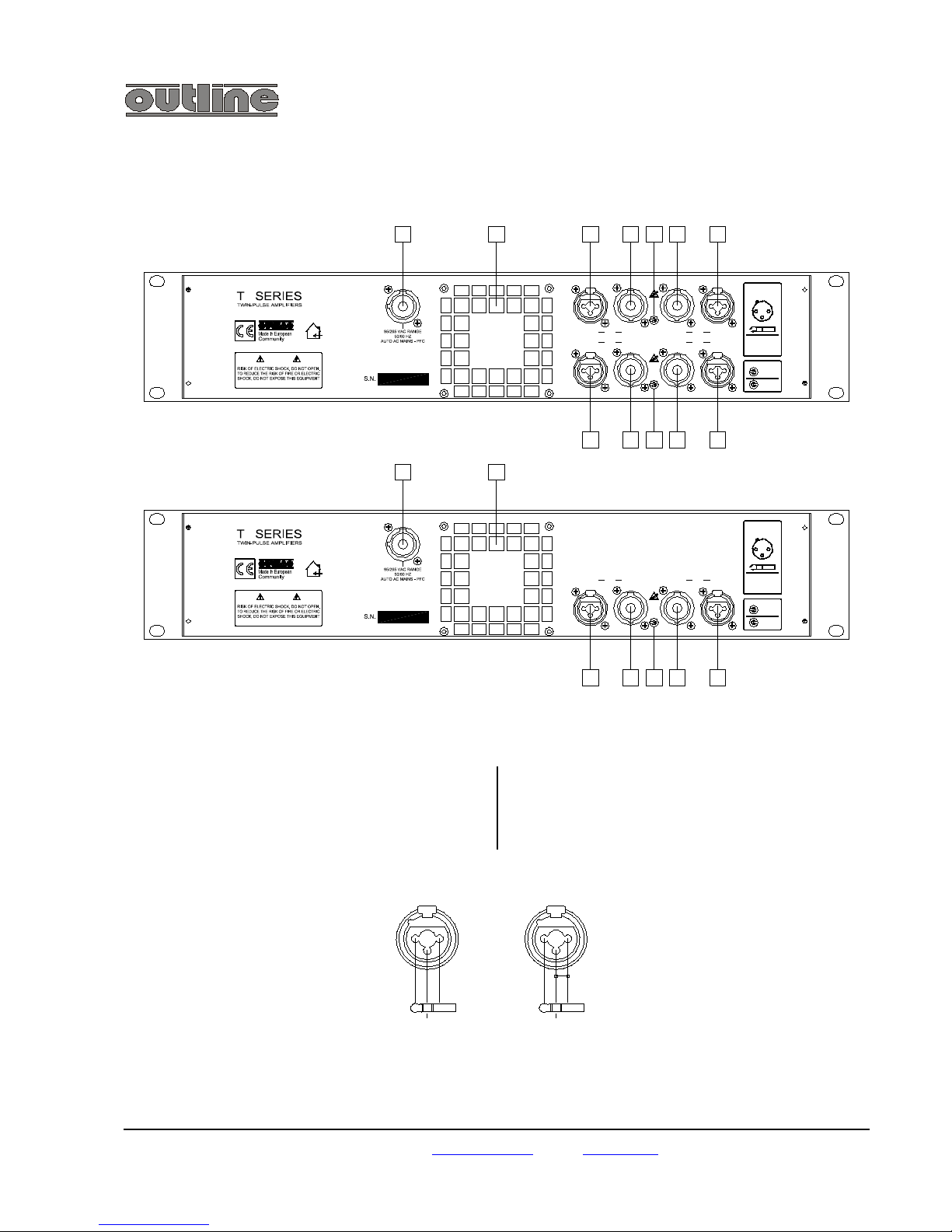
PANNELLO POSTERIORE / REAR PANEL
[1] MAINS : connettore per l’alimentazione da rete. Connettere
l’apposito cavo in dotazione.
[2] Aperture per il passaggio dell’aria di raffreddamento. Tenere
pulite a sgombre da ostacoli.
[1] MAINS: mains power connector. Connect the cable supplied
with the unit for this purpose.
[2] Cooling vents for correct air flow. Keep them clean and free
of obstacles.
[3] CH4 INPUT : connettori di tipo XLRCOMBO per l’ingresso del segnale del
Canale 4.
Pin 1: schermo (SHIELD)
Pin 2: segnale in fase (HOT)
Pin 3: segnale in contro-fase (COLD)
In caso di collegamento non bilanciato
collegare a massa il pin 3.
[4] CH4 OUTPUT : connettore Neutrik
Speakon femmina per l’uscita del Canale
4. Il polo positivo (in fase) è presente sul
terminale 1+, il polo negativo sul terminale
1-.
[3] CH4 INPUT: XLR-COMBO type
connectors for Channel 4 input signal.
Pin 1: shield
Pin 2: positive signal (HOT)
Pin 3: negative signal (COLD)
In the event of an unbalanced
connection, connect pin 3 to ground.
[4] CH4 OUTPUT: female Neutrik Speakon
connector for Channel 4 output. The
positive pole is on the 1+ pin, the negative
pole on the 1- pin.
outline s.n.c. di noselli g. & c. - v. leonardo da vinci, 56 - 25020 flero (bs) - italy - tel. +39-30-3581341 fax +39-30-3580431
Web Site: http://www.outline.it E-Mail : info@outline.it
3
INPUTS
STEREO
INPUTS LINK
2-1
5
1098 1211
10
2 = IN+
1 = GND
3 = IN -
SPEAKON
CONNECTED TO
1+/1-
12
3
12 3
INPUTS
STEREO
INPUTS LINK
2 - 1
4 - 3
2 = IN+
1 = GND
3 = IN -
SPEAKON
CONNECTED TO
1+/1-
12
3
12
TO RAIN OR MOISTURE.
CAUTION
INPUT OUTPUTCH2 OUTPUT C H1 INPUT
INPUT
INPUT
CH3
CH1OUTPUT
OUTPUTCH4
CH2 OUTPUT
OUTPUTINPUT
INPUT
TO RAIN OR MOISTURE.
CAUTION
1 2 3 4 6 7
121198
1 2
Page 6

T series power amplifiers professional audio page 4
[5] SELETTORE LINK per INPUTS 3 e 4 :
tipo di collegamento tra gli inputs 3 e 4:
– Levetta a sinistra per pilotare
entrambi i canali in uscita (OUTPUT
3 e 4) utilizzando un solo canale
d'ingresso (INPUT 3 o 4);
– Levetta a sinistra per pilotggio a
ponte di un'altoparlante, prelevando i
piedini “1+” dall' OUTPUT 3 e “1-”
dall'OUTPUT 4 (sempre utilizzando
un solo canale d'ingresso - INPUT 3
o 4);
– Levetta a destra per normale utilizzo
stereo (canali 3 e 4 completamente
indipendenti)
[5] INPUT 3 and 4 LINK SELECTOR: Type
of connection between inputs 3 and 4:
– LLever to the left to power both
channels’ outputs (OUTPUT 3 and 4)
using just one input channel (INPUT
3 or 4);
– LLever to the left for driving a
loudspeaker in bridged mode, taking
the “1+” leg of OUTPUT 3 and “1-” of
OUTPUT 4 (again only using a single
input channel - INPUT 3 or 4);
– Lever to the right for normal stereo
use (channels 3 and 4 completely
independent)
[6] CH3 OUTPUT : connettore Neutrik Speakon femmina per
l’uscita del Canale 3. Come [4].
[7] CH3 INPUT : connettori di tipo XLR-COMBO per l’ingresso
del segnale del Canale 3. Come [3].
[8] CH2 INPUT : connettori di tipo XLR-COMBO per l’ingresso
del segnale del Canale 2. Come [3].
[9] CH2 OUTPUT : connettore Neutrik Speakon femmina per
l’uscita del Canale 2. Come [4].
[6] CH3 OUTPUT: female Neutrik Speakon connector for
Channel 3 output. As [4].
[7] CH3 INPUT: XLR-COMBO type connectors for Channel 3
input signal. As [3].
[8] CH2 INPUT: XLR-COMBO type connectors for Channel 2
input signal. As [3].
[9] CH2 OUTPUT: female Neutrik Speakon connector for
Channel 2 output. As [4].
[10] SELETTORE LINK INPUTS 1 e 2 : tipo di collegamento
tra gli inputs 1 e 2. As [5]:
[10] INPUT 1 and 2 LINK SELECTOR: type of connection
between inputs 1 and 2. As [5]
[11] CH1 OUTPUT : connettore Neutrik Speakon femmina per
l’uscita del Canale 1. Come [4].
[12] CH1 INPUT : connettori di tipo XLR-COMBO per l’ingresso
del segnale del Canale 1. Come [3].
[11] CH1 OUTPUT: female Neutrik Speakon connector for
Channel 1 output. As [4].
[12] CH1 INPUT: XLR-COMBO type connectors for Channel 1
input signal. As [3].
outline s.n.c. di noselli g. & c. - v. leonardo da vinci, 56 - 25020 flero (bs) - italy - tel. +39-30-3581341 fax +39-30-3580431
Web Site: http://www.outline.it E-Mail : info@outline.it
Page 7
T series power amplifiers professional audio page 5
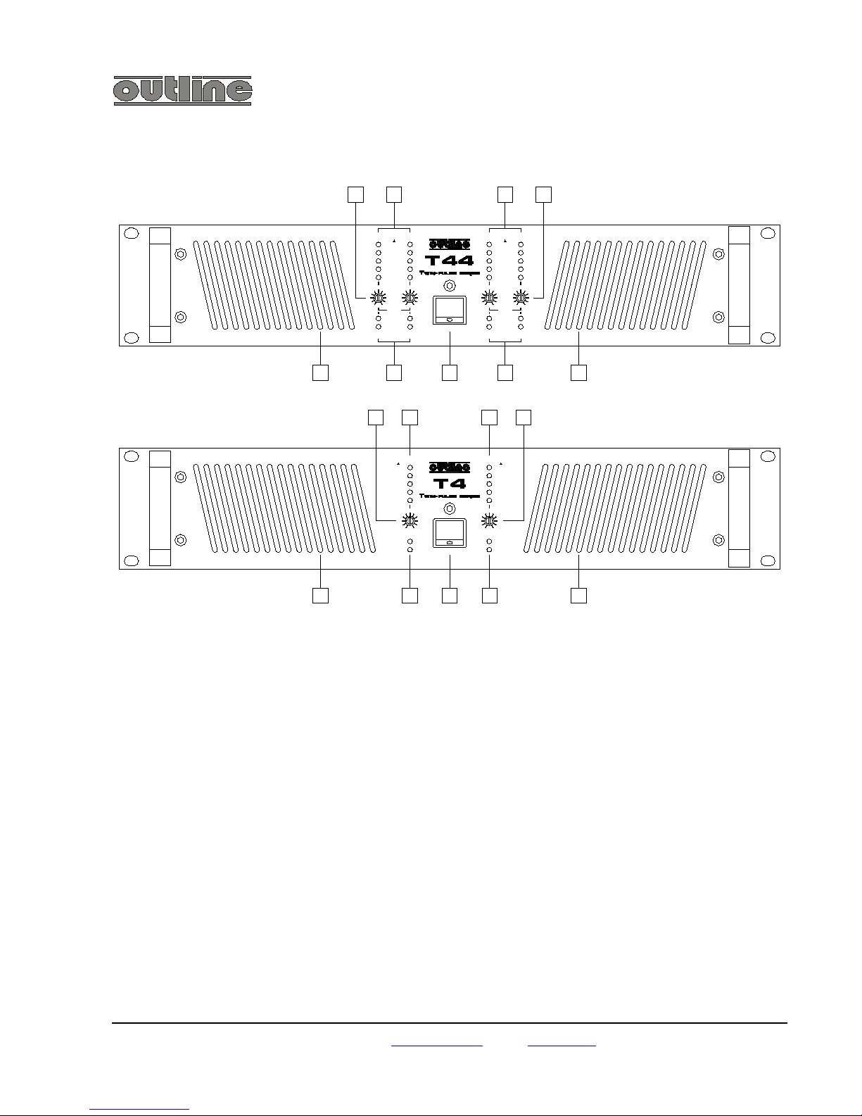
PANNELLO ANTERIORE / FRONT PANEL
outline s.n.c. di noselli g. & c. - v. leonardo da vinci, 56 - 25020 flero (bs) - italy - tel. +39-30-3581341 fax +39-30-3580431
Web Site: http://www.outline.it E-Mail : info@outline.it
PROT
READY
25%
SIGNAL
64
91
LEVEL
0 10
238
7
5
75%
50%
CLIP
100%
CH1
PROT
TEMP
75%
100%
25%
SIGNAL
50%
9
10
8
6
7
1
0
2
3
4
9
7
8
LEVEL
PROTECT
CH3/CH4
READY
5
0
4
1
3
2
TEMP
5
10
6
9
10
6
7
1
0
3
2
4
READY
8
5
9
7
8
0
4 6
10
TEMP
2
1
3
5
PROTECT
CH1/CH2
LEVEL
50%
SIGNAL
25%
75%
100%
CH3 CH4
CH1 CH2
CLIP
14 15 16
17 18 19 20 21
13
25%
SIGNAL
4 6
91
LEVEL
0 10
238
7
5
CLIP
100%
50%
75%
CH2
CLIP
1413 1615
1917 18 20 21
Page 8

T series power amplifiers professional audio page 6
[13] Regolazione LEVEL :
potenziometri rotativi per la regolazione della sensibilità
d’ingresso del Canale 1 (T4) o dei canali 1 e 2 (T44)
dell’amplificatore.
[14] Indicatori di livello sonoro:
VU METER a Led Canale 1 (T4) o canali 1 e 2 (T44).
viene visualizzata la potenza erogata, espressa in percentuale,
riferita alla massima potenza erogabile, istante per istante, nelle
reali condizioni di alimentazione. L’accensione del Led CLIP
indica la presenza in uscita della maggior potenza erogabile e la
conseguente entrata in funzione del circuito anti-clipping che
evita la saturazione del segnale.
[15] Indicatori di livello sonoro:
VU METER a Led Canale 2 (T4) o canali 3 e 4 (T44). Come [14].
[16] Regolazione LEVEL :
potenziometri rotativi per la regolazione della sensibilità
d’ingresso del Canale 2 (T4) o dei canali 3 e 4 (T44)
dell’amplificatore.
[17] Aperture per il passaggio dell’aria di raffreddamento.
Tenere pulite e sgombre da ostacoli.
[18] Segnalazioni.
- PROT: segnala la presenza di un corto circuito o di una
condizione di sovraccarico sull’uscita del relativo canale.
L'amplificatore tenterà il di ripristinarsi automaticamente
dopo 2 secondi. Se la condizione anomala è stata nel
frattempo rimossa, l'amplificatore riprenderà il normale
funzionamento, altrimenti tenterà per altre 19 volte il
ripristino automatico, dopodiché sarà da ripristinare
manualmente spegnendo l'apparecchio e rimuovendo la
causa dell'interruzione (corto circuito o sovraccarico).
- TEMP: segnala, lampeggiando, l'approssimarsi della
soglia di temperatura (circa 60°) oltre la quale entra in
funzione un limiter che comprime gradualmente il
segnale per stabilizzare la temperatura. In condizioni
normali questa spia continuerà a lampeggiare a meno
che non venga ridotta la potenza in uscita , per esempio
abbassando il volume.
Se, per una causa esterna, l’amplificatore si
surriscaldasse troppo (oltre 70°), l’apparecchio si
spegnerebbe e questa spia rimarrebbe accesa in modo
permanente. Una volta raffreddato, il finale riprende
automaticamente il normale funzionamento.
La protezione di temperatura agisce
contemporaneamente su 2 canali, quindi per il T4 si avrà
l'interruzione di funzionamento totale, mentre per il T44 si
interromperanno i canali 1 e 2 oppure i canali 3 e 4.
- READY: spia che si illumina dopo alcuni secondi
dall’accensione dell’amplificatore per segnalarne il
corretto funzionamento. Rimane accesa fino allo
spegnimento dell’apparecchio. La mancata accensione di
questa spia indica una anomalia nel funzionamento
dell’amplificatore; in questo caso contattare il centro di
assistenza più vicino.
[19] Interruttore generale di accensione/spegnimento
[20] Segnalazioni. Come [18]
[21] Aperture per il passaggio dell’aria di raffreddamento.
Come [17].
[13] LEVEL adjustment:
Rotary potentiometer for adjusting the input sensitivity of Channel
1 (T4) or channels 1 and 2 (T44) of the amplifier.
[14] Sound level indicators:
LED VU METERs for Channel 1 (T4) or channels 1 and 2 (T44).
Give real-time display of the power fed out, shown as a
percentage of the maximum power available, in real power
conditions. If the CLIP LED lights up, this indicates that the
maximum available power is being fed out and consequently the
anti-clipping circuit ha tripped to avoid signal saturation.
[15] Sound level indicators:
LED VU METER(s) for Channel 2 (T4) or channels 3 and 4 (T44).
As [14].
[16] LEVEL adjustment:
Rotary potentiometer for adjusting the input sensitivity of Channel
1 (T4) or channels 1 and 2 (T44) of the amplifier.
[17] Vents for the airflow for cooling.
Keep clean and free from obstacles.
[18] Warning lights.
- PROT: indicates a short circuit or overload condition on
the output of the channel in question. The amplifier will try
to automatically reset itself after two seconds. If the fault
condition has in the meantime been eliminated, the
amplifier will resume normal operation, if not, it will
attempt an automatic reset 19 more times, after which it
must be reset manually, switching the unit off and
eliminating the cause of the breakdown (short circuit or
overload).
- TEMP: flashes to indicate that the temperature threshold
(approximately 60°) has been reached. Above this level,
a limiter is triggered, gradually compressing the signal to
stabilize the temperature. Under normal conditions, this
light will continue to flash, unless the output power is
reduced – e.g. by lowering the volume.
If the unit overheats (over 70°) for external reasons, it will
switch off and this light will remain permanently lit. Once
it has cooled, the power amplifier will automatically
resume normal operation.
Temperature protection trips simultaneously on two
channels, so the T4 stops operating completely, whereas
with the T44, only channels 1 and 2 or channels 3 and 4
stop operating.
- READY: lights up approximately 10 seconds after the
amplifier is switched on, indicating regular operation. It
remains lit until the unit is switched off. If this warning
light fails to light up, this means there is a fault in the
amplifier’s operation; should this be the case, contact the
nearest service centre.
[19] Main ON/OFF switch
[20] Warning lights. As [18]
[21] Vents for airflow for cooling purposes.
As [17].
outline s.n.c. di noselli g. & c. - v. leonardo da vinci, 56 - 25020 flero (bs) - italy - tel. +39-30-3581341 fax +39-30-3580431
Web Site: http://www.outline.it E-Mail : info@outline.it
Page 9
T series power amplifiers professional audio page 7
INSTALLAZIONE / INSTALLATION
MONTAGGIO / RACK MOUNTING
L'amplificatore è stato progettato per il montaggio in rack
standard 19".
Dato la notevole profondità dell'apparecchiatura è importante
predisporre, nel caso di montaggio in contenitore rack, un
sostegno anche nella parte posteriore dell'unità.
A pagina 11 sono mostrati gli ingombri dell'amplificatore.
This amplifier has been designed for 19" standard rack mounting.
Due to the unit’s considerable depth, if it is rack-mounted, a
support must also be fitted at the rear of the unit.
The amplifier’s dimensions can be found on Page 11.
VENTILAZIONE / VENTILATION
L'amplificatore, nel suo regolare funzionamento, necessita di un
adeguato raffreddamento che può avvenire per ventilazione
forzata o naturale.
L'installazione dell'amplificatore deve quindi prevedere aperture
che consentano un flusso d'aria di almeno 45 m3/h.
Le prese d'aria [17] e [21] si trovano sul pannello anteriore,
mentre l'uscita [2] avviene dal pannello posteriore.
Nel caso di montaggio di più amplificatori in un unico mobile, il
ricambio d'aria può essere insufficiente; è consigliabile quindi
dotare il contenitore stesso di ventilazione forzata.
È opportuno che questo ricambio d'aria avvenga con aspirazione
dal basso ed emissione in alto.
For regular operation, the amplifier requires sufficient cooling,
which can be forced or natural.
Amplifier installation must therefore provide vents enabling an air
flow of at least 45 m3/hr.
The air intakes [17] and [21] are on the front panel, whereas air is
fed out through the rear panel [2].
When several amplifiers are mounted in the same rack, air flow
may be insufficient; it’s therefore advisable to equip the frame
with a forced air-cooling unit.
It is best for the air flow to be taken in at the bottom of the rack
and fed out at the top.
PRECAUZIONI PER L'INSTALLAZIONE / INSTALLATION PRECAUTIONS
L’installazione in luoghi eccessivamente umidi o polverosi può
causare danni o mal funzionamenti dell’apparecchio.
Posizionare l’apparecchio quanto più lontano possibile da
sintonizzatori o apparecchi televisivi. L’amplificatore può infatti
essere all’origine di rumori o interferenze nella ricezione radio o
televisiva.
Installation in excessively damp or dusty surroundings could lead
to the unit’s damage or faulty operation.
Position the unit as far as possible from radio tuners or TV sets.
The amplifier can in fact cause noise or interference with radio or
television reception.
CABLAGGIO / CABLING
Collegamento ingressi / Input connections
Consigli per l'esecuzione dei collegamenti di ingresso
· Usare solo cavi schermati coassiali di alta qualità.
· I collegamenti non bilanciati devono essere il più corti
possibile (non superare i 3/4 metri).
· Non posizionare cavi di segnale a basso livello vicino ad altri
con segnali ad alto livello (cavi altoparlanti) e a cavi di
alimentazione. Questo evita l'introduzione di disturbi per
induzione.
· NON COLLEGARE tra loro le masse di ingresso e di uscita
per non creare ground loops.
· Disalimentare l'amplificatore prima di eseguire cambiamenti
nei collegamenti.
· Ricordarsi che si opera con un sistema in grado di erogare
potenze istantanee molto elevate.
Tips on input connections
· Only use high quality screened coax cables.
· Unbalanced connections must be as short as possible (do
not exceed 3-4 metres in length).
· Do not run low-level signal cables near others carrying high
level signals (loudspeaker cables) or power cables. This
prevents induction interference.
· DO NOT CONNECT input and output grounds together, to
avoid creating ground loops.
· Always switch the amplifier off before making connection
changes.
· Always remember that this unit is able to deliver very high
impulsive power.
outline s.n.c. di noselli g. & c. - v. leonardo da vinci, 56 - 25020 flero (bs) - italy - tel. +39-30-3581341 fax +39-30-3580431
Web Site: http://www.outline.it E-Mail : info@outline.it
Page 10

T series power amplifiers professional audio page 8
Collegamento uscite / Output connection
Osservare la corretta polarità nel collegamento degli altoparlanti
per avere i segnali di uscita in fase con quelli di ingresso.
ATTENZIONE:
· Non collegare le due uscite tra di loro o con le uscite di
altri amplificatori.
· Non cortocircuitare le uscite.
· Le uscite sono sempre sollevate da massa, anche in
assenza di segnale; non connettere mai il polo negativo
alla carcassa dell'amplificatore.
Date le elevate potenze in gioco si consiglia l’installazione di
fusibili di protezione per le casse acustiche.
Usare cavi per il collegamento degli altoparlanti di sezione
adeguata alla lunghezza del collegamento.
Cavi di sezione ridotta provocano perdita di potenza in linea con
conseguente riscaldamento del cavo.
Keep the correct polarity when connecting loudspeakers, to
ensure that the output signals are in phase with the input signals.
WARNING:
· Do not connect the two outputs with each other, or with
other amplifiers’ outputs.
· Do not short circuit the outputs.
· The outputs are always lifted from ground; never
connect the negative pole to the amplifier’s frame.
Due to the high power involved, it is advisable to install fuses for
the loudspeaker enclosures.
When connecting loudspeakers, choose cables with a suitable
cross-section for the length of the cable run required.
Cables with a small cross-section cause loss of power and cable
overheating.
Affidabilità dei collegamenti / Connector reliability
Usare buoni connettori, meccanicamente stabili e con portata in
corrente adeguata per evitare cortocircuiti accidentali.
NOTA : l'amplificatore è dotato di protezione dai cortocircuiti, ma
se questi avvengono in presenza di forte pilotaggio in ingresso,
l'intervento può non essere abbastanza tempestivo per non
provocare danni.
Use high-quality, mechanically stable connectors, with a proper
power capacity, in order to avoid accidental short circuits.
N.B. The amplifier is equipped with short circuit protection, but
should a short circuit occur with a high input level, it may not trip
quickly enough to prevent damage.
COLLEGAMENTO ALLA RETE / MAINS SUPPLY CONNECTION
L'amplificatore è equipaggiato di un cavo a 3 conduttori dotato di
relativo connettore PowerCon a 3 poli (fase,neutro e messa a
terra connessa al telaio); si richiede di mantenere la connessione
a terra anche in caso di prolungamento del cavo, adattamento a
prese esistenti, riduzioni, etc.
IL COSTRUTTORE DECLINA OGNI RESPONSABILITÀ DA
EVENTUALI DANNI PROVOCATI DALLA NON OSSERVANZA
DI TALE NORMA
The amplifier is supplied with a 3-conductor cable fitted with
relative 3-pole Powercon mains connector, whose centre
(ground) contact is connected to the chassis: the ground must
also be connected in the case of extension cables or adapters
for existing sockets, etc. being used.
THE MANUFACTURER DISCLAIMS ALL RESPONSIBILITY
FOR ANY DAMAGES CAUSED BY NON-OBSERVANCE OF
THIS NORM
FUSIBILI DI RETE / FUSES
L’amplificatore è dotato di fusibile di rete, ma non è accessibile
dall’esterno. In caso di rottura contattare il più vicino centro di
assistenza.
The amplifier is supplied with a mains power fuse, which is
inaccessible from the outside. Should it blow or break, contact
the nearest assistance centre.
outline s.n.c. di noselli g. & c. - v. leonardo da vinci, 56 - 25020 flero (bs) - italy - tel. +39-30-3581341 fax +39-30-3580431
Web Site: http://www.outline.it E-Mail : info@outline.it
Page 11
T series power amplifiers professional audio page 9
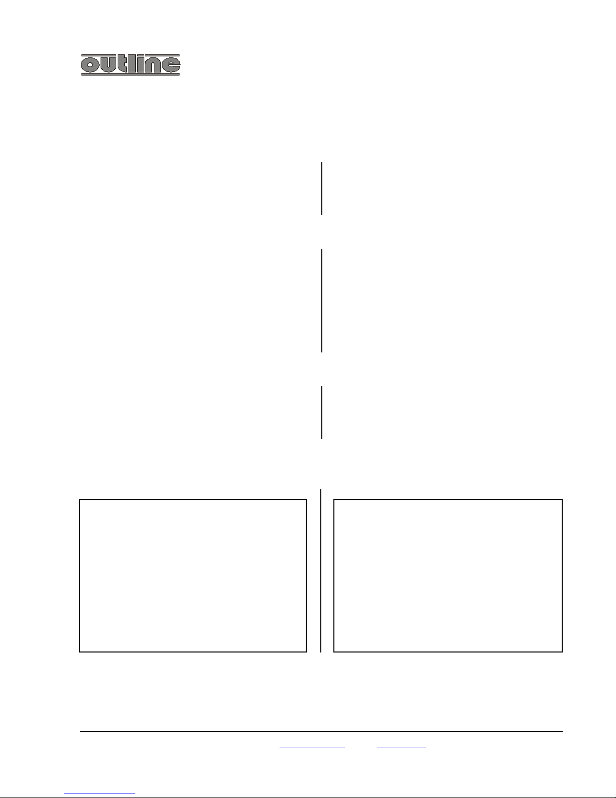
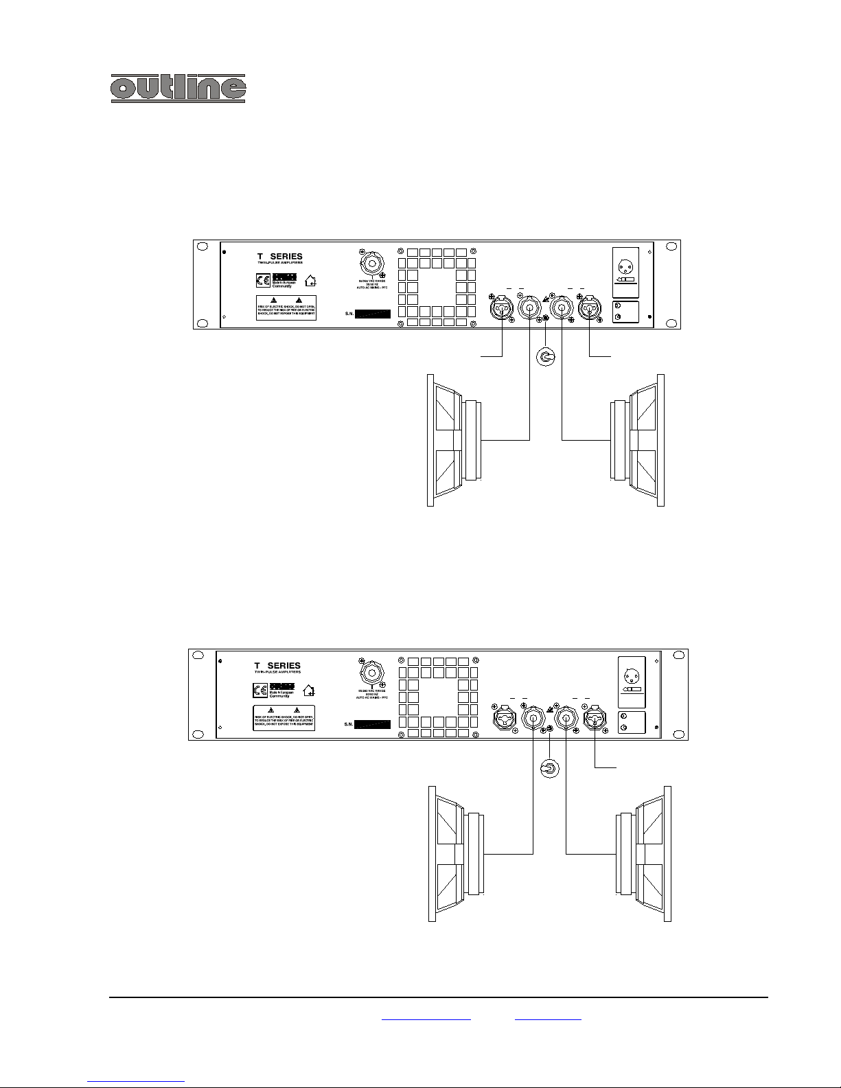
ESEMPI DI COLLEGAMENTO / CONNECTION EXAMPLES
1 - Collegamento stereo – Stereo connection
2 - Collegamento parallelo – Parallel connection
outline s.n.c. di noselli g. & c. - v. leonardo da vinci, 56 - 25020 flero (bs) - italy - tel. +39-30-3581341 fax +39-30-3580431
Web Site: http://www.outline.it E-Mail : info@outline.it
3
INPUTCH2INPUT CH1OUTPUTOUTPUT
LINKED
IN2
INPUTS
STEREO
SPEAKON
1+/1-
IN1
CONNECTED TO
2 3 1
1 = GND
2 = IN+
3 = IN -
2 1
CAUTION
TO RAIN OR MOISTURE.
Input signal 1Input signal 2
1+/1-
CH2 OUTPUT
1+/1-
CH1 OUTPUT
CAUTION
TO RAIN OR MOISTURE.
INPUTCH2INPUT OUTPUT OUTPUT CH1
3 = IN -
2 = IN+
1 = GND
SPEAKON
IN1
1+/1-
CONNECTED TO
STEREO
INPUTS
IN2
LINKED
2 3
2
3
1
1
Input signal
CH1 OUTPUT
1+/1-1+/1-
CH2 OUTPUT
Page 12

T series power amplifiers professional audio page 10
3 – Collegamento a ponte – Bridged mode
outline s.n.c. di noselli g. & c. - v. leonardo da vinci, 56 - 25020 flero (bs) - italy - tel. +39-30-3581341 fax +39-30-3580431
Web Site: http://www.outline.it E-Mail : info@outline.it
TO RAIN OR MOISTURE.
CAUTION
INPUTCH2INPUT OUTPU T OUTPUT CH1
LINKED
IN2
INPUTS
STEREO
CONNECTED TO
1+/1-
IN1
SPEAKON
1 = GND
2 = IN+
3 = IN -
23321
1
Input signal
1+
CH1 OUTPUT
CH2 OUTPUT
1-
Page 13

T series power amplifiers professional audio page 11
DIMENSIONI MECCANICHE / MOUNTING DIMENSIONS
outline s.n.c. di noselli g. & c. - v. leonardo da vinci, 56 - 25020 flero (bs) - italy - tel. +39-30-3581341 fax +39-30-3580431
Web Site: http://www.outline.it E-Mail : info@outline.it
PROT
READY
25%
SIGNAL
64
91
LEVEL
0 10
238
7
5
75%
50%
CLIP
100%
CH1
PROT
TEMP
25%
SIGNAL
4 6
91
LEVEL
0 10
238
7
5
CLIP
100%
50%
75%
CH2
Page 14

T series power amplifiers professional audio page 12
SPECIFICHE TECNICHE / SPECIFICATIONS
Potenza impulsiva in uscita con entrambi i canali pilotati
EIAJ (1%THD)
Continuous rated output power - both channels driven EIAJ (1%
THD)
T4 (8/4/2 ):
T4 (8/4 ):
T44 (8/4 ):
T44 (8 ):
2 x 500/830/1500 W (due canali)
1 x 1660/3000 W (collegamento a ponte)
4 x 600/1000 W (quattro canali)
2 x 2000 W (collegamento a ponte)
T4 (8/4/2 ):
T4 (8/4 ):
T44 (8/4 ):
T44 (8 ):
2x 500/830/1500 W (2-channels)
1x 1660/3000 W (bridged mode)
4x 600/1000 W (4-channels)
2x 2000 W (bridged mode)
Impedenza di ingresso:
20 K
Input impedance:
20 K
Sensibilità di ingresso: Input sensitivity:
T4:
T44
1.41 Vrms
1.58 Vrms
T4:
T44
1.41 Vrms
1.58 Vrms
Guadagno in tensione: Voltage gain:
T4:
T44:
32 dB
32 dB
T4:
T44:
32 dB
32 dB
Massimo livello in ingresso
10dBV
Maximum input level
10dBV
THD da 0,1W a piena potenza
<0.5% (tipica 0,01%)
THD from 0.1 W to full power
<0.5% (typical 0.01%)
Rapporto segnale/disturbo
105 dBA
Signal:noise ratio
105 dBA
Diafonia
90 dB
Crosstalk
90 dB
Slew rate
40 V/usec (filtro ingresso escluso)
Slew rate
40 V/usec (input filter by-passed)
Tempo di salita
1 usec Rise time 1 usec
Fattore di smorzamento (8 )
600 @ 100 Hz
100 @ 10 kHz
Damping factor (8 )
600 @ 100 Hz
100 @ 10 kHz
Banda passante
5 Hz÷30 kHz
Bandwidth
5 Hz÷30 kHz
Protezioni interne dell’amplificatore Amplifier protections
Sovraccarico
Carichi corto circuitati
Cortocircuito verso massa
Soft clipping
Overload
Short circuited loads
Short circuited to ground
Soft clipping
Protezioni del carico Load protections
Ritardo all’accensione
Corrente continua
Segnali subsonici
Alta frequenza
Riduzione automatica ad ¼ della potenza per i segnali stazionari
Start-up / shutdown transient
DC fault
Sub-sonic signals
High frequency
Automatic power reduction to ¼ on stationary signals
Ventilazione :
1 ventola 45 m3/h
Cooling :
1 fan - 45 m3/h
Circuitazione Circuitry
Totalmente switching, la sezione alimentatore lavora ad una
frequenza di campionamento di 125 kHz, la sezione finale a 250 kHz.
Full switching, the power section runs at 125 kHz and the output
stage at 250 kHz sampling frequency.
Dispositivi di potenza
16
Power output devices
16
Connessioni ingressi
XLR Combo
Input connectors
XLR Combo
outline s.n.c. di noselli g. & c. - v. leonardo da vinci, 56 - 25020 flero (bs) - italy - tel. +39-30-3581341 fax +39-30-3580431
Web Site: http://www.outline.it E-Mail : info@outline.it
Page 15

T series power amplifiers professional audio page 13
Connessioni uscite :
Neutrik Speakon NL4MP
Output connectors :
Neutrik Speakon NL4MP
Tensione di alimentazione :
95/265 Vac 50/60 Hz
Power requirements :
95/265 Vac 50/60 Hz
Consumo (1/8 potenza nominale su 4 ) Power consumption (1/8 nominal power on 4 )
T4:
T44:
500 VA
900 VA
T4:
T44:
500 VA
900 VA
Dimensioni :
483 mm x 452 mm x 88 mm
2U standard EIA
Dimensions:
483 mm x 452 mm x 88 mm
2U standard EIA
Peso :
10 Kg / T4, 11 Kg / T44
Weight :
10 kg (T4) - 11 kg (T44)
outline s.n.c. di noselli g. & c. - v. leonardo da vinci, 56 - 25020 flero (bs) - italy - tel. +39-30-3581341 fax +39-30-3580431
Web Site: http://www.outline.it E-Mail : info@outline.it
Page 16

NOTE / NOTES
Page 17

R
PROFESSIONAL AUDIO
Outline s.n.c.
di Noselli Guido & C.
Via Leonardo da Vinci, 56
25025 Flero BS - ITALY
Phone : ++39 (0) 30/3581341
Fax : ++39 (0) 30/3580431
E-mail : info@outline.it
Internet : www.outline.it
 Loading...