

Page 1

Professional Mixers
Mixer PRO405 1
PRO405 MIXER
Il PRO405 racchiude, nella sua compattezza, tutte le
caratteristiche di un grande mixer come tradizione della serie
“PRO” Outline.
All’estetica decisamente curata ed innovativa si assomma una
circuitazione di alto livello.
Progettato per funzionare ininterrottamente con stabilità ed
affidabilità, il PRO405 fornisce prestazioni di qualità senza
guasti e senza manutenzione.
Grazie alla sua versatilità il PRO405 si trova a suo agio sia in
discoteca tra i giradischi del banco DJ, dove occupa lo stretto
indispensabile, che in casa dell’amatore.
Il PRO405 è parte di un sistema espandibile. E’ possibile,
Although its small dimensions, the PRO405 has all the
characteristics of a great mixer according to the tradition of
the Outline PRO series.
Aesthetically this unit points out an innovative aspec t as well
as the greatest care for detail which combine with a circuitry
of high quality.
PRO405 mixer is designed to work ininterruptly with high
stability and affordability, with high performances and no
faults or maintenance.
Thanks to its versatility the PRO405 is suitable for discos,
where it occupies the bare minimum among turntables on DJ’s
desk, as well as in hi-fi amateurs’ houses.
Page 2

Professional Mixers
2 Mixer PRO405
infatti, collegare fra loro due mixer PRO405 mediante
un’apposita connessione che non sottrae ingressi utili.
L’accoppiamento di due mixer PRO405 consente di ottenere la
dimensione standard rack.
The PRO405 is part of an expandable system. In fact, it is
possible to link two PRO405 mixers together by using a builtin special connection which does not occupy any of the input
channels.
The mechanical coupling of two PRO405 mixers allows us to
obtain a 19” rack standard dimension.
Page 3
Professional Mixers
Mixer PRO405 3
AUXILIARY
0 0 0 0
ON
BALANCE
BASS
MID
HIGH
OFF1 2
A-SELECT
4
CLIP
646
MON
IN
10 10
1
OFF
L R
-15 +15
-100+10
-150+15
-15 +15
4
810 9
CROSSFADER
7 6 5 4 3
0 1 2 3 4 5 6 7
2 1 0
3 OFF
98 10
B-SELECT
DJ MICPROG
TALKOVER ON
+15
MIX
-15
0
BASS
OFF
CLIP
4
6
MON
IN
10
4
6
4
CLIP
6
10
MON
IN
10
A 2
OFF ON
CLIP
MON
4
6
10
IN
464
6
10
8 8 8
8
8 8 8 8
10
3 BON4
OFF ON
L R
-15 +15
BALANCE
L
BASS
-15
-100+10
-150+15
MID
-10
0
HIGH
-15
0
BALANCE
R L
BASS
+15 -15R+15
MID
+10 -10
HIGH
+15 -15
0
+10
0
+15
CLIP 0
ADJ
HIGH
DJ MIC
LEVEL
2
1
3
0 10
5
4 6
2
1
3
0 10
5
4 6
MASTER
LEVEL
8
9
7
LEVEL
9
8
7
L+R
IN
-20
-10
-7
-5
READING
OUTPUTS
MAIN OUT
MONITOR
SELECT
-3
-1
0dB
+1
+2
+3
VU
INPUT
GAIN
15
12
-20
9
6
0dB
3
1
DJ MIC
PHONES
PRO405
12
15
-2090dB
6
3
2
12
15
GAIN
INPUT
-20
9
6
3
INPUT
GAIN
0dB
3
12
15
-2090dB
6
3
4
MONITOR LINK
3/41/2
PROGRAM
MON
MONITOR
CUE
MIX
LEVEL
MONITOR
ADJADJ
0 0
2 2
0 0
2 2
0 0
2 2
0 0
2 2
Page 4

Professional Mixers
4 Mixer PRO405
INTRODUZIONE
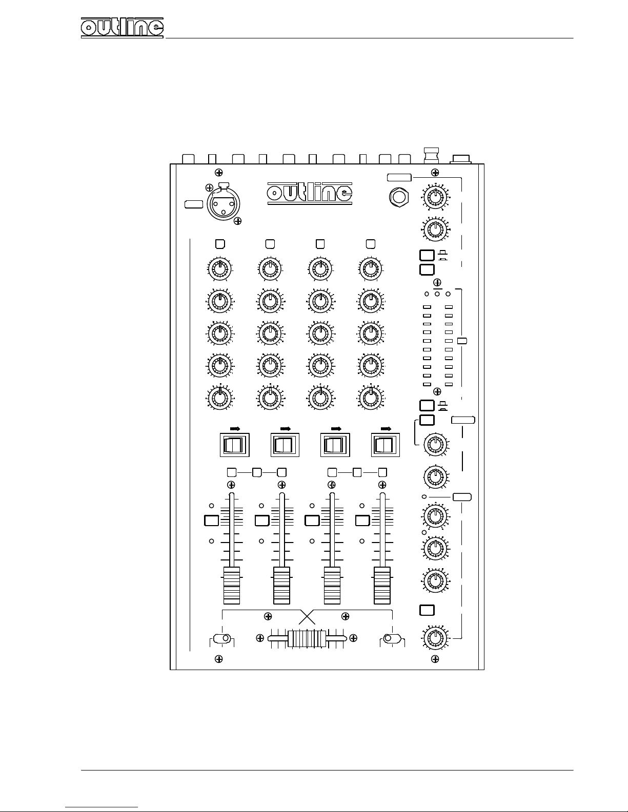
Il mixer PRO405 è così composto:
INTRODUCTION
PRO405 mixer has the following features:
n N. 4 ingressi PHONO/LINE stereo e MICRO mono commutabili
dal pannello posteriore.
L'ingresso BAL MIC consente l'utilizzo di microfoni
bilanciati e non bilanciati mediante connettore Jack.
Gli ingressi PHONO e LINE sono di tipo non bilanciato ed
utilizzano connettori Pin RCA.
Per ognuno di questi ingressi sono disponibili:
• La regolazione del guadagno (INPUT GAIN).
• Tre regolazioni di tono (High, Mid, Bass).
• Il bilanciamento (BALANCE).
• Il commutatore (OFFðON) per l'inserzione
dell'ingresso.
• Il tasto (MON) per l'invio dell'ingresso al sistema di
monitor.
• L'indicatore di sovraccarico (CLIP).
• L'input fader a potenziometro slider corsa 60 mm.
A questi 4 ingressi è asservito un Crossfader a
potenziometro slider corsa 45 mm.
All'estremo sinistro (A) del Crossfader può essere
assegnato l'ingresso 1 o l'ingresso 2 mediante il
commutatore a 3 posizioni A-SELECT, mentre all'estremo
destro (B) l'ingresso 3 o l'ingresso 4 mediante B-SELECT.
Con i due commutatori in posizione centrale (Off), il
Crossfader è disattivato.
n N. 1 ingresso DJ MIC.
L'ingresso è di tipo bilanciato e utilizza un connettore di
tipo XLR sul frontale del mixer.
E' dotato di:
• Regolazione del guadagno mediante cacciavite (GAIN).
• Due regolazioni di tono (HIGH, BASS).
• Indicatore di sovraccarico (CLIP).
• Input fader a potenziometro rotativo (LEVEL).
• Tasto per l'inserzione del microfono DJ con effetto
talkover (TALKOVER ON).
Inserendo la funzione Talkover si avrà in uscita il risultato
della miscelazione fra il programma (ingressi 1,2,3,4) e il
DJ Mic effettuata mediante potenziometro rotativo. In
caso contrario il DJ MIC non è attivo.
n Sezione OUTPUTS.
Sono disponibili due uscite:
• L’uscita principale MAIN.
• L’uscita secondaria AUXILIARY .
Entrambe le uscite sono di tipo sbilanciato e sdoppiate.
Utilizzano connettori Pin RCA.
I livelli sono controllati mediante potenziometri rotativi
(MASTER LEVEL e AUXILIARY LEVEL).
L'uscita secondaria (AUXILIARY ) può essere messa in mono
premendo il tasto In L+R e, durante l'installazione, può
essere subordinata all'uscita principale.
n Sezione PHONES.
Per l'ascolto in cuffia è disponibile una presa Jack di tipo
n # 4 stereo PHONO/LINE and mono MICRO inputs selectable
from back panel.
BAL MIC input allows use of balanced and unbalanced
microphones by means of Jack connector.
PHONO and LINE inputs are unbalanced and have RCA Pin
connectors.
For each input the following features are available:
• Gain adjusting (INPUT GAIN).
• Three-band tone controls (High, Mid, Bass).
• BALANCE adjusting.
• Input insertion switch (OFFðON).
• Sending button of the input to the Monitor Bus (MON).
• Overload indicator (CLIP).
• Input fader with 60 mm travel slide potentiometer.
The 4 inputs are selectable on a crossfader with a 45 mm
slider.
It is possible to assign to the left end of the crossfader (A)
either input 1 or 2 by means of the three-position ASELECT switch, while input 3 or 4 can be given to the right
end by B-SELECT switch.
By selecting the centre position (Off) on both A-Select and
B-Select switches, crossfader is not in use.
n DJ MIC input.
This is a balanced input which makes use of a XLR
connector on the front panel of the unit.
This input has the following features:
• Screwdriver gain control (GAIN).
• Two-band tone controls (HIGH, BASS).
• Overload indicator (CLIP).
• Input fader with rotary potentiometer (LEVEL).
• DJ’s microphone insertion button with talkover
function (TALKOVER ON).
By selecting talkover, the mixing of the program (inputs 1,
2, 3 and 4) with DJ’s microphone will be sent to the output
by the rotary potentiometer. If talkover is not selected,
DJ MIC is not active.
n OUTPUTS section.
Two outputs are available:
• Main output.
• Auxiliary output.
Both outputs are unbalanced, doubled and make use of
RCA Pin connectors.
Levels are controlled by rotary potentiometers (MASTER
LEVEL and AUXILIARY LEVEL).
AUXILIARY output is selectable a s mono by pressing in L+R
button and, during the installation, can be subordinated
to the main output level control.
n PHONES section.
Phones monitoring and volume control can be effected by
a stereo Jack with the relative level control (MONITOR
LEVEL).
Page 5

Professional Mixers
Mixer PRO405 5
stereo con relativo controllo di livello (MONITOR LEVEL).
Con il tasto PROGRAM/MON si può scegliere cosa ascoltare
in cuffia: il programma oppure gli ingressi selezionati con i
relativi tasti MON (con livelli pre-fader e subordinati al
CUE).
La funzione CUE MONITOR permette di simulare in cuffia
un crossfader fra gli ingressi 1/2 e 3/4.
Il tasto MONITOR LINK permette di sentire in cuffia il
monitor di un secondo mixer collegato, mediante apposito
cavo, ai connettori sul retro (LINK).
n Sezione VU METERS.
Con il tasto MAIN OUT/MONITOR è possibile visualizzare
con le scale LED (dinamica 23 dB) l'uscita principale (MAIN)
oppure il monitor (ciò che si sente in cuffia).
The PROGRAM/MON button selects the signal to be sent on
phones monitoring: either the program or the inputs
selected by the relative MON buttons (with pre-fader
levels and subordinated to the CUE).
CUE MONITOR function allows having a simulation (on
phones monitoring circuit) of a cross-fading between
inputs 1-2 and 3-4.
MONITOR LINK button enables us to have on phones the
monitor line of a second PRO405 mixer linked, by proper
cable, to the rear connectors (LINK).
n VU METERS section.
MAIN OUT/MONITOR button switch allows visual monitor
by LED bars (23 dB dynamics) of MAIN output or monitor
(what you listen on phones).
Page 6
Professional Mixers
6 Mixer PRO405
SEZIONE INGRESSI 1-2-3-4 :
PHONO/MICRO/LINE
1-2-3-4 INPUTS SECTION :
PHONO/MICRO/LINE
Il tipo di ingresso è selezionabile dal retro,
dove si trovano anche i connettori.
Sul pannello frontale del mixer sono presenti i
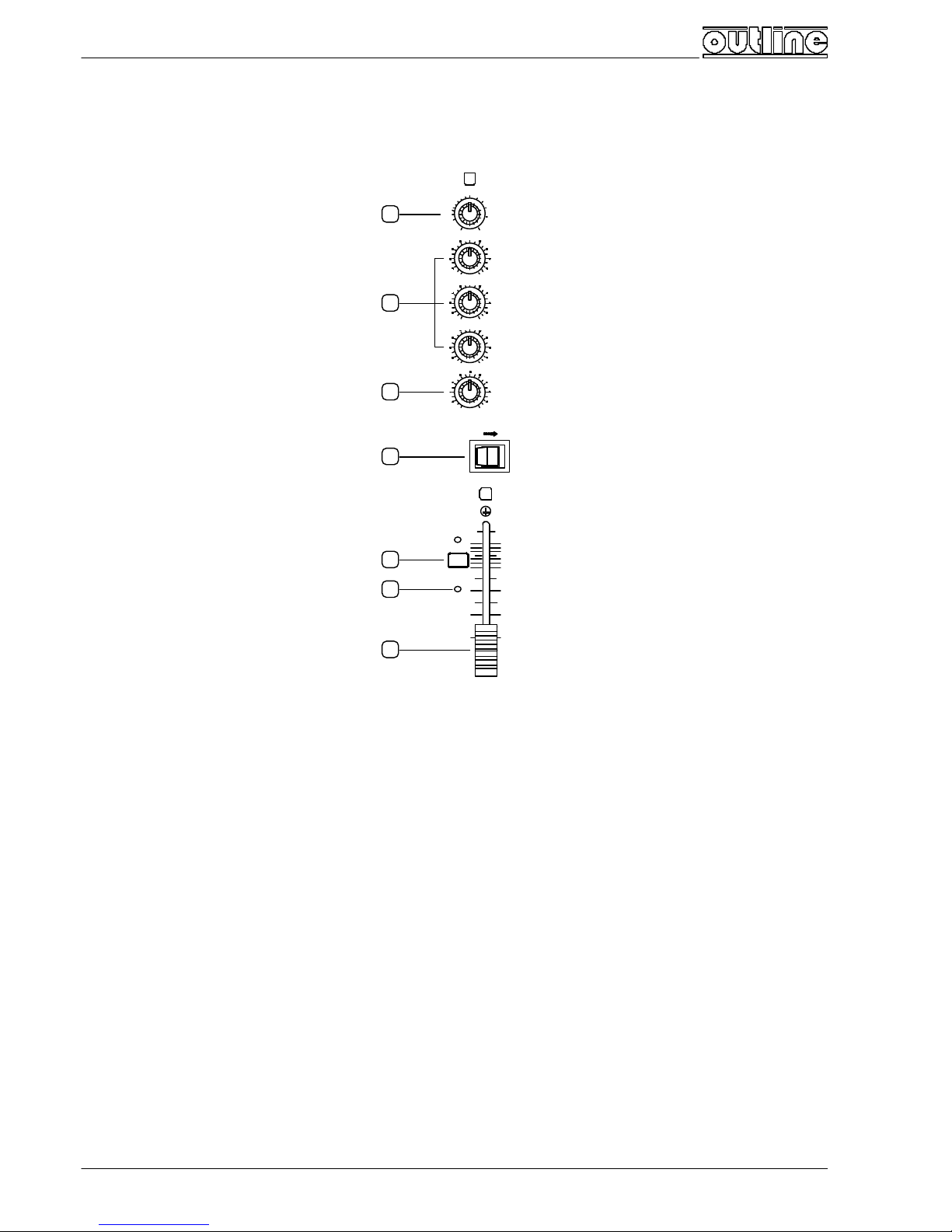
seguenti controlli :
INPUT GAIN : potenziometro rotativo che
consente di regolare il guadagno del primo
stadio preamplificatore entro 20 dB per
tutti i tipi di segnale.
HIGH-MID-BASS : controlli sezione
equalizzatrice.
HIGH: ±12 dB a 20000 Hz
MID: ±10 dB a 2000 Hz
BASS: ±15 dB a 20 Hz
BALANCE : controllo del bilanciamento del
segnale tra i canali destro e sinistro per
definirlo quantitativamente nello spettro
stereofonico.
OFF ð ON : inserzione dell’ingresso. Invia il
segnale after -fader (sotto il controllo
dell’input fader) ai bus di programma.
MON : tasto per l’invio del segnale pre-fader
alla sezione monitor. Il LED giallo (IN)
indica che la funzione è attiva.
CLIP : indicatore di sovraccarico dello stadio
preamplificatore.
INPUT FADER : controllo del livello del segnale
mediante potenziometro slider con corsa
60 mm.
1
2
3
4
5
6
7
0
ON
BALANCE
BASS
MID
HIGH
4
CLIP
646
MON
IN
10 10
1
OFF
L R
-15 +15
-100+10
-150+15
8
8
INPUT
GAIN
15
12
-20
9
6
0dB
3
1
0 0
2 2
The input mode is selectable from the rear
panel, where connectors are located.
On the front panel of the mixer are placed the
following controls :
INPUT GAIN : rotary potentiometer which
allows adjusting within a 20 dB range the
gain of the first preamplifier stage, for all
types of signal.
HIGH-MID-BASS : equalization section controls.
HIGH: ±12 dB @ 20000 Hz
MID: ±10 dB @ 2000 Hz
BASS: ±15 dB @ 20 Hz
BALANCE : balance control between left and
right channels signal levels, to adjust
correct balancing in stereo program
output.
OFF ð ON : Input channel insertion. Sending of
after -fader signal (under input fader
control) to program buses.
MON : Key for sending pre-fade level signal to
monitor section. Yellow LED (IN) lights
when the module is active.
CLIP : overload indicator of the preamplifier
circuitry.
INPUT FADER : signal level controls effected by
means of a slide potentiometer with 60
millimetres travel.
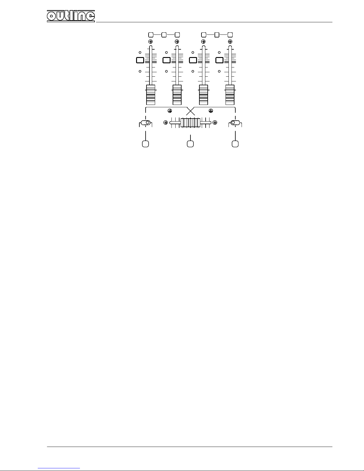
SEZIONE CROSSFADER
CROSSFADER SECTION
Page 7
Professional Mixers
Mixer PRO405 7
[8] A-SELECT : commutatore per
l’assegnazione degli ingressi 1 e
2 all’estremità A del crossfader.
In posizione centrale (OFF)
nessuno dei due ingressi è
assegnato.
CROSSFADER : potenziometro slider
che permette la miscelazione (al
centro) e la dissolvenza graduale
degli ingressi assegnati a questa
sezione. In posizione A vengono
annullati i gli ingressi che fanno
capo all’estremità B e viceversa.
I livelli degli ingressi assegnati alla
sezione crossfader sono
comunque subordinati ai relativi
input fader.
B-SELECT : commutatore per
l’assegnazione degli ingressi 3 e
4 all’estremità B del crossfader.
In posizione centrale (OFF)
nessuno dei due ingressi è
assegnato.
OFF1 2
A-SELECT
4
CLIP
646
MON
IN
10 10
1
4810 9
CROSSFADER
7 6 5 4 3
0 1 2 3 4 5 6 7
2 1 0 3 OFF
98 10
B-SELECT
CLIP
4
6
MON
IN
10
4
6
4
CLIP
6
10
MON
IN
10
A 2
CLIP
MON
4
6
10
IN
464
6
10
8 8 8
8
8 8 8 8
10
3 B 4
0 0
2 2
0 0
2 2
0 0
2 2
0 0
2 2
8 109
[8] A-SELECT : commutatore per
l’assegnazione degli ingressi 1 e
2 all’estremità A del crossfader.
In posizione centrale (OFF)
nessuno dei due ingressi è
assegnato.
CROSSFADER : potenziometro slider
che permette la miscelazione (al
centro) e la dissolvenza graduale
degli ingressi assegnati a questa
sezione. In posizione A vengono
annullati i gli ingressi che fanno
capo all’estremità B e viceversa.
I livelli degli ingressi assegnati alla
sezione crossfader sono
comunque subordinati ai relativi
input fader.
B-SELECT : commutatore per
l’assegnazione degli ingressi 3 e
4 all’estremità B del crossfader.
In posizione centrale (OFF)
nessuno dei due ingressi è
assegnato.
Page 8

Professional Mixers
8 Mixer PRO405
SEZIONE MICRO DJ
MICRO DJ SECTION
A differenza degli altri ingressi, questo si
trova direttamente sul pannello frontale
del mixer.
DJ MIC: connettore di tipo XLR per
ingresso microfonico.
Pin 1: schermo (GND)
Pin 2: segnale in fase (HOT)
Pin 3: segnale in controfase (COLD)
In caso di collegamento non bilanciato
collegare il pin 3 a massa (pin 1).
DJ MIC
PRO405
11
2 3 1
Differently other inputs, this is located
on the front panel of the mixer.
DJ MIC : XLR-type connector for micro
input.
Pin 1: shield (GND)
Pin 2: phase signal (HOT)
Pin 3: phase inverted signal (COLD)
In case of unbalanced input connect pin 3
to ground (pin 1).
[12] ADJ : regolazione del guadagno del primo
stadio preamplificatore da 0dB a -∞. Viene
effettuata mediante cacciavite agendo su
un trimmer multigiri.
LEVEL : controllo del livello del segnale mediante
potenziometro rotativo.
CLIP : indicatore di sovraccarico dello stadio
preamplificatore.
HIGH-BASS : controlli sezione equalizzatrice.
HIGH: ±15 dB a 20000 Hz
BASS: ±15 dB a 60 Hz
TALKOVER ON : tasto per l’inserzione del Micro
DJ con funzione talkover.
13
15
17
12
14
16
-15 +15
DJ MICPROG
TALKOVER ON
+15
MIX
-15
0
BASS
CLIP
0
ADJ
HIGH
DJ MIC
LEVEL
[12] ADJ : gain adjustment on preamp first
stage, with a range from 0 dB to -∞. This
adjustment is made operating with a
screwdriver on a multiturn trimmer.
LEVEL : signal level control by rotary
potentiometer.
CLIP : overload indicator of the preamplifier
circuitry.
HIGH-BASS : equalization section controls.
HIGH: ±15 dB @ 20000 Hz
BASS: ±15 dB @ 60 Hz
TALKOVER ON : DJ microphone insertion button
with talkover function.
[17] MIX : Quando la funzione Talkover è attiva è possibile
dosare le quantità di segnale del programma e del
microfono DJ da mandare in uscita.
In posizione MIX si hanno entrambi i segnali; ruotando la
manopola verso PROG si ha una graduale diminuzione del
livello del Micro DJ fino ad azzerarlo, ruotando in senso
opposto è il segnale di programma a diminuire.
Quando la funzione Talkover è disinserita è come se ci si
trovasse in posizione PROGRAM e quindi il Micro DJ è
escluso.
[17] MIX : When talkover is active, it is possible to control the
levels of program signal and of DJ’s microphone signal to
send to outputs.
In MIX position both signals are present: rotating the knob
anti-clockwise (PROG) the signal from DJ’s Mic fades out
to zero, rotating the knob clockwise (DJ MIC) it is the
program signal which fades out.
When talkover is not in use, Program is on and DJ’s
microphone is off-line
SEZIONE USCITE
OUTPUTS SECTION
Sono disponibili due uscite : MAIN OUT (principale)
e AUXILIARY OUT (secondaria).
L’uscita secondaria può venire subordinata, in
sede di installazione, a quella principale (come
spiegato nelle “Personalizzazioni” a pagina 10).
IN L+R : tasto che permette di rendere monofonica
Two outputs are available : MAIN OUT and
AUXILIARY OUT.
During the installing procedure of the mixer, the
auxiliary output may be subordinated to the main
output (see “Customizations ” at page 10).
IN L+R : by pressing this button AUXILIARY OUT
Page 9

Professional Mixers
Mixer PRO405 9
(L+R) l’uscita AUXILIARY.
AUXILIARY LEVEL : potenziometro rotativo per il
controllo del livello del segnale dell’uscita
AUXILIARY.
MASTER LEVEL : potenziometro rotativo per il
controllo del livello del segnale dell’uscita
MAIN.
18
19
20
AUXILIARY
2
1
3
0 10
5
4 6
2
1
3
0 10
5
4 6
MASTER
LEVEL
8
9
7
LEVEL
9
8
7
L+R
IN
OUTPUTS
becomes mono (L+R).
AUXILIARY LEVEL : rotary potentiometer for MAIN
output level control .
MASTER LEVEL : rotary potentiometer for MAIN
output level control.
Page 10

Professional Mixers
10 Mixer PRO405
SEZIONE MONITOR E VU METERS
VU METERS AND MONITOR SECTION
[21] PHONES : presa cuffia stereo (Jack ¼”) per
l’ascolto in cuffia della linea monitor.
N.B. NON COLLEGARE Jack mono.
MONITOR LEVEL : potenziometro rotativo per la
regolazione del livello di ascolto in cuffia.
CUE MONITOR : Questa funzione permette di
preascoltare in cuffia una simulazione di quello
che si può ottenere con il crossfader ed è
attiva solamente quando il tasto
PROGRAM/MON [24] è premuto.
Nella posizione centrale (MIX) è presente in cuffia
la somma di tutti i segnali pre-fader che sono
stati inviati al monitor tramite la pressione
dei relativi tasti MON [5].
PROGRAM/MONITOR : tasto per la scelta di ciò che
si desidera ascoltare in cuffia: i segnali prefader selezionati con i tasti MON [5] (tasto
PROGRAM/MON premuto) oppure il programma
in uscita prima della regolazione di livello.
MONITOR LINK : questo tasto viene utilizzato solo
in caso di collegamento del mixer con un altro
PRO405 Outline.
Permette ascoltare in cuffia la linea di monitor del
secondo mixer collegato. Il segnale viene
sommato a quello già presente sulla linea
monitor.
27
23
21 22
24
25
26
28
-20
-10
-7
-5
READING
MAIN OUT
MONITOR
SELECT
-3
-1
0dB
+1
+2
+3
VU
PHONES
MONITOR LINK
3/41/2
PROGRAM
MON
MONITOR
CUE
MIX
LEVEL
MONITOR
ADJADJ
[21] PHONES : stereo phones outlet (¼” Jack) for
monitoring.
N.B. DO NOT CONNECT mono Jack.
MONITOR LEVEL : rotary potentiometer for
phones level adjusting.
CUE MONITOR : This function allows us to hear
previously on phones a simulation of what is
possible to obtain using the crossfader. This
operation can be effected only when the
PROGRAM/MON button [24] is pressed.
In centre position (MIX) the signal on phones is the
sum of all the pre-fader signals sent to the
monitor by pressing the relative MON buttons
[5].
PROGRAM/MONITOR : this button selects the signal
to be sent on phones: either the pre-
fader
signals selected by MON buttons [5]
(PROGRAM/MON button pressed) or the
output program (before Main Level control).
MONITOR LINK : button used only if another Outline
PRO 405 mixer is connected.
It sends on phones the monitor line of the second
mixer linked.
The signal is summed to the one already present on
the monitor line.
[26] ADJ : controlli per la taratura dei Vu meters.
VU meter a LED con rivelatore di precisione e dinamica di 23
dB.
MAIN OUT/MONITOR : tasto per la scelta di ciò che si desidera
visualizzare con le scale LED: il segnale dell’uscita Main
oppure quello disponibile in cuffia (tasto premuto).
[26] ADJ : Vu meters calibration controls.
LED bar VU meter with precision detector and 23 dB dynamics.
MAIN OUT/MONITOR : key for visualization of level on LEDs
scales : it is possible to choose between the Main output
signal or the signal sent on phones (key depressed).
Page 11

Professional Mixers
Mixer PRO405 11
PANNELLO POSTERIORE / REAR PANEL
29
POWER
LINK slave
R
L
R
Made in Italy by
LINK master
L
R
L
R
MIC
AUXILIARY LINE
R
L
BAL
R
MIC MIC
LINE
BAL
R
L
R
BAL
MIC
LINE LINE
BAL
R
L
R
L
MAIN OUTPUTS
L
4
PHONO PHONO
L
3 2
PHONO PHONO
L
1
OUTPUTS
Flero - Brescia
30
31
32
33 353637
3834 363738 363738 36
3739 39 39 39
38
[29] POWER : interruttore di alimentazione del mixer.
Morsetto per i collegamenti di massa (telaio).
Connettore DB9 maschio per il collegamento al trasformatore
di alimentazione in dotazione al mixer.
LINK master : connettore per la connessione con un altro
mixer PRO405 (segnali in ingresso).
LINK slave : connettore per la connessione con un altro mixer
PRO405 (segnali in uscita).
MAIN OUTPUTS : connettori Pin RCA per l’uscita MAIN.
L’uscita è di tipo sbilanciato ed è sdoppiata.
AUXILIARY OUTPUTS : connettori Pin RCA per l’uscita
AUXILIARY. L’uscita è di tipo sbilanciato ed è sdoppiata.
Commutatori a 3 posizioni per la selezione del tipo di ingresso :
PHONO/MICRO/LINE.
BAL MIC : connettore Jack 1/4” per segnali microfonici
bilanciati. In caso di utilizzo in modo sbilanciato
utilizzare un Jack di tipo mono.
Ingresso sbilanciato Ingresso bilanciato
Gnd Hot Gnd HotCold
PHONO : connettori Pin RCA per segnali provenienti da
giradischi (equalizzazione RIAA).
[29] POWER: AC mains ON/OFF button switch of the mixer
unit.
Binding Post for chassis GND connection.
Male DB9 connector for the connection of the mixer to the AC
mains transformer supplied with the mixer unit.
LINK master : connection to another PRO405 mixer (incoming
signals).
LINK slave : connection to another PRO405 mixer (outcoming
signals).
MAIN OUTPUTS : RCA Pin connectors for MAIN output. This
output is unbalanced and doubled.
AUXILIARY OUTPUTS : : RCA Pin connectors for AUXILIARY
output. This output is unbalanced and doubled.
Three-position switches for PHONO/MICRO/LINE input
selection.
BAL MIC : 1/4” Jack connector for balanced microphonic
signals. If it is used with unbalanced signals, a mono Jack
is required.
Unbalanced input Balanced input
Gnd Hot Gnd HotCold
PHONO : RCA Pin connectors for signals coming from
turntables (RIAA equalization).
Page 12

Professional Mixers
12 Mixer PRO405
LINE : connettori Pin RCA per segnali proventi da sorgenti non
bilanciate.
LINE : RCA Pin connectors for signals coming from unbalanced
sources.
Page 13

Professional Mixers
Mixer PRO405 13
ACCOPPIAMENTO MECCANICO DI DUE MIXER
PRO405
MECHANICAL COUPLING OF TWO PRO405
MIXERS
Le meccaniche del PRO405 sono state studiate per consentire
l’accoppiamento di due unità nel rispetto delle dimensioni
standard rack 19”.
The PRO405 cabinet dimensions have been studied in order to
obtain a coupling of two units in compliance with 19”
standard rack dimensions.
279.5 352.5
483
465
436
AUXILIARY
0 0 0 0
ON
BALANCE
BASS
MID
HIGH
OFF1 2
A-SELECT
4
CLIP
646
MON
IN 10 10
1
OFF
L R
-15 +15
-100+10
-150+15
-15 +15
4810 9
CROSSFADER
7 6 5 4 3
0 1 2 3 4 5 6 7
2 1 0 3 OFF
98 10
B-SELECT
DJ MICPROG
TALKOVER ON
+15
MIX
-15
0
BASS
OFF
CLIP
4
6
MON
IN 10
464
CLIP
6
10
MON
IN 10
A 2
OFF ON
CLIP
MON
4
6
10 IN
464
6
10
8 8 8 8 8 8 8 8
10
3 BON4
OFF ON
L R
-15 +15
BALANCE
L
BASS
-15
-100+10
-150+15
MID
-10
0
HIGH
-15
0
BALANCE
R L
BASS
+15 -15R+15
MID
+10 -10
HIGH
+15 -15
0
+10
0
+15
CLIP 0
ADJ
HIGH
DJ MIC
LEVEL
2
1
3
0 10
5
4 6
2
1
3
0 10
5
4 6
MASTER
LEVEL
8
9
7
LEVEL
9
8
7
L+R
IN
-20
-10
-7
-5
READING
OUTPUTS
MAIN OUT
MONITOR
SELECT
-3
-1
0dB
+1
+2
+3
VU
INPUT
GAIN
15
12
-20
9
6
0dB
3
1
DJ MIC
PHONES
PRO405
12
15
-2090dB
6
3
2
12
15
GAIN
INPUT
-20
9
6
3
INPUT
GAIN
0dB
3
12
15
-2090dB
6
3
4
MONITOR LINK
3/41/2
PROGRAM
MON
MONITOR
CUE
MIX
LEVEL
MONITOR
ADJADJ
0 0
2 2
0 0
2 2
0 0
2 2
0 0
2 2
Il fissaggio dei due mixer si ottiene smontando il fondo del
mixer di destra e infilando 3 viti filettate M3 x 10 mm testa
esagonale negli appositi fori come mostra la figura qui sotto.
Dopo aver affiancato i due mixer si procede ad avvitare. Le
viti troveranno le apposite sedi filettate nel fianchetto del
mixer di sinistra. Una volta rimontato il fondo mancate si avrà
un unico mobile pronto per essere fissato in un rack con le
apposite alette in dotazione.
The coupling of two units is obtained by removing the bottom
panel of the right mixer and putting three M3 x 10 mm hex
screws in the relative holes, as shown below. After having
placed the two mixers side by side, tighten the screws in the
three threaded holes in the left mixer side. Once the bottom
panel of the right mixer is definitively put in place, the two
mixers will form a single cabinet which could be rack-mounted
using the relative rack mount hardware.
Page 14

Professional Mixers
14 Mixer PRO405
Page 15

Professional Mixers
Mixer PRO405 15
COLLEGAMENTO DI DUE MIXER PRO405
TWO PRO405 MIXERS LINK
Il collegamento viene effettuato mediante l’apposito cavo in
dotazione.
Use the special connecting cable supplied with the unit.
POWER
LINK slave
R
L
R
Made in Italy by
LINK master
L
R
L
R
MIC
AUXILIARY LINE
R
L
BAL
R
MIC MIC
LINE
BAL
R
L
R
BAL
MIC
LINE LINE
BAL
R
L
R
L
MAIN OUTPUTS
L
4
PHONO PHONO
L
3 2
PHONO PHONO
L
1
OUTPUTS
Flero - Brescia
POWER
LINK slave
R
L
R
Made in Italy by
LINK master
L
R
L
R
MIC
AUXILIARY LINE
R
L
BAL
R
MIC MIC
LINE
BAL
R
L
R
BAL
MIC
LINE LINE
BAL
R
L
R
L
MAIN OUTPUTS
L
4
PHONO PHONO
L
3 2
PHONO PHONO
L
1
OUTPUTS
Flero - Brescia
MASTER SLAVE
Una volta realizzato il collegamento tra due mixer ci si trova in
una tipica configurazione Master -Slave con le seguenti
caratteristiche:
• Le uscite del mixer principale (Master) sono in grado di
raccogliere i segnali miscelati di entrambe i mixer. La
regolazione di livello generale viene eseguita sul mixer
principale.
• Le uscite del mixer secondario (Slave) raccolgono solo i
segnali miscelati applicati allo stesso mixer (Slave).
La regolazione di livello generale del mixer è ancora attiva, ma
agisce solo nell’ambito dello stesso mixer.
• In questa situazione abbiamo realmente a disposizione un
mixer con 10 ingressi e 4 uscite stereo.
• Mediante l’interconnessione si realizza anche un
collegamento bidirezionale tra i circuiti di monitoraggio,
consentendo il preascolto incrociato tra le varie unità
subordinato all’azione del commutatore Monitor Link [25].
The linking of two mixers forms a typical Master-Slave
configuration with the following characteristics:
• Outputs of Master mixer are able to pick up the signals
present on the output lines of both units. The master
volume adjust is executed by the Master Level knob of
the Master unit.
• Slave mixer outputs are only relative to the signals mixed
in the slave unit itself.
Master level adjust on Slave mixer is still active, but only for
the same Slave unit.
• In a two-unit system as depicted above, 10 stereo inputs
and 4 stereo outputs are available.
• By linking two units is activated a bi-directional
monitoring connection which allows the cross-cueing
among the different units according to the position of
Monitor Link switch [25].
MASTER SLAVE
Monitor Link
A B
A or B B or A
• Per ulteriori espansioni con la stessa logica di collegamento
(come specificato nella figura sottostante), contattare
l’ufficio tecnico Outline.
• Following the same technique it is possible to effect
further expansions. Contact the Outline Technical Office
for this kind of connection.
Page 16

Professional Mixers
16 Mixer PRO405
MASTER
MIX
A+B+C
C
SLAVE 1
MIX
A+B
B
SLAVE 2
MIX
A
A
Page 17

Professional Mixers
Mixer PRO405 17
PERSONALIZZAZIONI / CUSTOMIZATIONS
SENSIBILITÀ VU METERS
La sensibilità della lettura dei VU
meters con il controllo [28] in
posizione MAIN OUT fa si che alla
posizione 0dB della scala
corrisponda un segnale di 0dBm
(0.775V) sull’uscita MAIN .
Lavorando con segnali molto elevati
potrebbe verificarsi la necessità di
abbassare la sensibilità dei VU
meters che, altrimenti,
raggiungerebbero subito il fondo
scala.
Spostando due ponticelli sul C.S.
AM13-2 è possibile des
ensibilizzare
la lettura di 10dB. Lo 0dB della
barra LED indicherà quindi il livello
+10dBm in uscita.
Standard
0dB=0dBm
0dB=10dBm
C24
R21
R20
18.01.94
AM13-2
R22
R18
R17
R16
R24
D8
X7
X9
C23
+
R37
R36
IC7
C28
C27
R41
+
R38
C21
C22
C26
C25
X8
X8 X8
VU METERS SENSITIVITY
The sensitivity of VU meters
reading with [28] control placed in
MAIN OUT position is set to make
0dB of the LED bars correspond to
a 0dBm (0.775V) signal level on MAIN
output.
In particular, feeding the inputs
with high-level signals, may require
a lowering of VU -meters sensitivity,
in order to avoid the continuous
reaching of full-scale on the
instruments.
By moving two jumpers on # AM13-2
PCB it is possible to decrease by 10
dB the reading sensitivity. 0dB of
the LED bar will indicate +10dBm
effective output level.
USCITA AUXILIARY DERIVATA
DALL’USCITA MAIN
È possibile che per determinate
applicazioni sia preferibile
subordinare le uscite Auxiliary
all’uscita Main (per esempio la
sonorizzazione di una seconda
pista da ballo). Il PRO405 è stato
predisposto per consentire questo
cambiamento, basta spostare due
ponticelli sul C.S. UM16-2.
In questo modo l’uscita Auxiliary
diventa un sottocanale dell’uscita
Main.
Standard
Uscite indipendenti
Uscita Auxiliary subordinata al Master level dell'uscita Main
SW2
SW2
+15V
GND
-15V
X3
C21
R40
R46
P6
R39
C22
SW2
IC6
R38
P7
POST
PRE
R50
R49
R48
P8
C28
R45
IC8
R47
C27
C25
SW4SW3
C26
Auxiliary out subordinated to the Main out Master level
Indipendents outputs
AUXILIARY OUTPUT DERIVED FROM
MAIN OUTPUT
In particular applications may be
preferable to submit Auxiliary
outputs to Main Output (for
example to diffuse music program
on a secondary dance-floor).
PRO405 allows this moving two
jumpers on # UM16-2 PCB.
This way Auxiliary channel program
becomes a Main output subchannel.
ACCESSORI
ACCESSORIES
IN DOTAZIONE
• T TRP405
Trasformatore 40 VA 120/240 VAC 50/60 Hz.
Fusibile 500 mAT.
Assicurarsi di aver predisposto la tensione
corretta prima di alimentare il
trasformatore.
SUPPLIED WITH THE UNIT
• T TRP405
40 VA 120/240 VAC* 50/60 Hz transformer.
500 mAT fuse.
Be sure about correct setting of voltage
changeover before connecting to AC
mains.
*For Japan the supply voltage is only 100
Page 18

Professional Mixers
18 Mixer PRO405
A RICHIESTA
• Cavo per il collegamento con un altro
mixer PRO405.
• Alette per l’incasso del mixer.
Vac.
OPTIONAL
• Cable for the connection to another
Outline PRO405 mixer.
• Rack mount hardware.
Page 19

Professional Mixers
Mixer PRO405 19
DIMENSIONI MECCANICHE / EXTERNAL AND MOUNTING DIMENSIONS
352.5
POWER
LINK slave
R
L
R
Made in Italy by
LINK master
L
R
L
R
MIC
AUXILIARY LINE
R
L
BAL
R
MIC MIC
LINE
BAL
R
L
R
BAL
MIC
LINE LINE
BAL
R
L
R
L
MAIN OUTPUTS
L
4
PHONO PHONO
L
3 2
PHONO PHONO
L
1
OUTPUTS
Flero - Brescia
279.5
AUXILIARY
0 0 0 0
ON
BALANCE
BASS
MID
HIGH
OFF1 2
A-SELECT
4
CLIP
646
MON
IN
10 10
1
OFF
L R
-15 +15
-100+10
-150+15
-15 +15
4
810 9
CROSSFADER
7 6 5 4 3
0 1 2 3 4 5 6 7
2 1 0
3 OFF
98 10
B-SELECT
DJ MICPROG
TALKOVER ON
+15
MIX
-15
0
BASS
OFF
CLIP
4
6
MON
IN
10
4
6
4
CLIP
6
10
MON
IN
10
A 2
OFF ON
CLIP
MON
4
6
10
IN
464
6
10
8 8 8 8
8
8 8 8
10
3 BON4
OFF ON
L R
-15 +15
BALANCE
L
BASS
-15
-100+10
-150+15
MID
-10
0
HIGH
-15
0
BALANCE
R L
BASS
+15 -15R+15
MID
+10 -10
HIGH
+15 -15
0
+10
0
+15
CLIP 0
ADJ
HIGH
DJ MIC
LEVEL
2
1
3
0 10
5
4 6
2
1
3
0 10
5
4 6
MASTER
LEVEL
8
9
7
LEVEL
9
8
7
L+R
IN
-20
-10
-7
-5
READING
OUTPUTS
MAIN OUT
MONITOR
SELECT
-3
-1
0dB
+1
+2
+3
VU
INPUT
GAIN
15
12
-20
9
6
0dB
3
1
DJ MIC
PHONES
PRO405
12
15
-2090dB
6
3
2
12
15
GAIN
INPUT
-20
9
6
3
INPUT
GAIN
0dB
3
12
15
-2090dB
6
3
4
MONITOR LINK
3/41/2
PROGRAM
MON
MONITOR
CUE
MIX
LEVEL
MONITOR
ADJADJ
0 0
2 2
0 0
2 2
0 0
2 2
0 0
2 2
265
247
218
352.5
88
105
Page 20

Professional Mixers
20 Mixer PRO405
SCHEMA A BLOCCHI / BLOCK DIAGRAM
VU METERS
MAIN OUT
MONITOR
AUXILIARY OUT
L
R
AUXILIARY
LEVEL
MAIN
LEVEL
L+R
MAIN OUT
L
R
MON IN
MONITOR LINK
LINK
CONNECTORS
PHONES
MON 3-4 L
MON 3-4 R
MON 1-2 L
MON 1-2 R
PROGRAM R
PROGRAM L
MON
PROGRAM
CUE MONITOR
TALKOVER ON
CLIP
LEVEL
- EQ
HILO
HIMIDLO
HIMIDLO
GAIN
ADJUST
FADER
INPUT
MICRO DJ
CROSSFADERBALANCE
CLIP
- EQ
- EQ
INPUT GAIN
+0 -20dB
+0 -20dB
INPUT GAIN
PHONO R
LINE R
MICRO
LINE L
PHONO L
Page 21

Professional Mixers
Mixer PRO405 21
SPECIFICHE TECNICHE
SPECIFICATIONS
INGRESSI 1-4 : MICRO
1-4 INPUTS : MIC
Impedenza di ingresso :
Sensibilità :
Massimo livello di ingresso :
5 KΩ
-48 dBV (4 mV)
-12.4 dBV (240 mV)
Input impedance :
Input sensitivity :
Maximum input level :
5 KΩ
-48 dBV (4 mV)
-12.4 dBV (240 mV)
INGRESSI 1-4 : LINEA
1-4 INPUTS : LINE
Impedenza di ingresso :
Sensibilità :
Massimo livello di ingresso :
68 KΩ
-17 dBV (140 mV)
+28.6 dBV (27 V)
Input impedance :
Input sensitivity :
Maximum input level :
68 KΩ
-17 dBV (140 mV)
+28.6 dBV (27 V)
INGRESSI 1-4 : PHONO
1-4 INPUTS : PHONO
Impedenza di ingresso :
Sensibilità :
Massimo livello di ingresso :
Equalizzazione RIAA :
47 KΩ
-46.8 dBV (4.5 mV)
-1.4 dBV (850 mV)
±0.3 dB
Input impedance :
Input sensitivity :
Maximum input level :
RIAA equalization :
47 KΩ
-46.8 dBV (4.5 mV)
-1.4 dBV (850 mV)
±0.3 dB
CONTROLLI DI TONO INGRESSI 1-4
1-4 INPUTS TONE CONTROLS
Alti :
Medi :
Bassi :
±12 dB a 20000 Hz
±10 dB a 2000 Hz
±15 dB a 20 Hz
High :
Mid :
Bass :
±12 dB @ 20000 Hz
±10 dB @ 2000 Hz
±15 dB @ 20 Hz
INGRESSO MICRO DJ
MIC DJ I NPUT
Impedenza di ingresso :
Sensibilità :
Massimo livello di ingresso :
5 KΩ
-55.5 dBV (1.6 mV)
-2 dBV (800 mV)
Input impedance :
Input sensitivity :
Maximum input level :
5 KΩ
-55.5 dBV (1.6 mV)
-2 dBV (800 mV)
CONTROLLI DI TONO INGRESSO MICRO DJ
MIC DJ INPUT TONE CONTROLS
Alti :
Bassi :
±15 dB a 20000 Hz
±15 dB a 60 Hz
High :
Bass :
±15 dB @ 20000 Hz
±15 dB @ 60 Hz
THD :
<0.03%
THD :
<0.03%
IMD :
<0.06%
IMD :
<0.06%
DIAFONIA :
>55 dB a 1000 Hz
CROSSTALK :
>55 dB at 1000 Hz
RISPOSTA IN FREQUENZA
Ingressi micro :
Ingressi linea :
Ingressi phono :
20 Hz ÷ 20000 Hz -0.5 dB
5 Hz ÷ 38000 Hz -3 dB
20 Hz ÷ 20000 Hz -1 dB
5 Hz ÷ 39000 Hz -3 dB
RIAA
FREQUENCY RESPONSE
Mic inputs :
Line inputs :
Phono inputs :
20 Hz ÷ 20000 Hz -0.5 dB
5 Hz ÷ 38000 Hz -3 dB
20 Hz ÷ 20000 Hz -1 dB
5 Hz ÷ 39000 Hz -3 dB
RIAA
USCITA MAIN
Impedenza di uscita :
Livello nominale di uscita :
Livello massimo di uscita :
50 Ω
0 dBm (775 mV)
+19 dB
MAIN OUTPUT
Output impedance :
Output nominal level :
Maximum output level :
50 Ω
0 dBm (775 mV)
+19 dB
USCITA AUXILIARY
Impedenza di uscita :
Livello nominale di uscita :
Livello massimo di uscita :
50 Ω
0 dBm (775 mV)
+19 dB
AUXILIARY OUTPUT
Output impedance :
Output nominal level :
Maximum output level :
50 Ω
0 dBm (775 mV)
+19 dB
RAPPORTO SEGNALE/RUMORE
Ingresso micro DJ :
Lin 70 dBV A 79 dBV
SIGNAL/NOISE RATIO
1 micro DJ input :
Lin 70 dBV A 79 dBV
Page 22

Professional Mixers
22 Mixer PRO405
1 ingresso micro :
4 ingressi micro :
1 ingresso linea :
4 ingressi linea :
1 ingresso phono :
4 ingressi phono :
Lin 70 dBV A 79 dBV
Lin 68 dBV A 76 dBV
Lin 72 dBV A 83 dBV
Lin 71 dBV A 81 dBV
Lin 60 dBV A 70 dBV
Lin 60 dBV A 70 dBV
1 micro input :
4 micro inputs :
1 line input :
4 line inputs :
1 phono input :
4 phono inputs :
Lin 70 dBV A 79 dBV
Lin 68 dBV A 76 dBV
Lin 72 dBV A 83 dBV
Lin 71 dBV A 81 dBV
Lin 60 dBV A 70 dBV
Lin 60 dBV A 70 dBV
ALIMENTAZIONE :
120/240 Vac 50/60 Hz 40VA
POWER SUPPLY :
120/240 Vac 50/60 Hz 40VA
(100 Vac for Japan)
DIMENSIONI :
218 mm x 365 mm x 105 mm
DIMENSIONS :
218 mm x 365 mm x 105 mm
PESO :
4 Kg netto, 5 Kg lordo
WEIGHT :
Net 4 Kg, gross 5 Kg
ELENCO COMPONENTI PER RICHIESTA RICAMBI
SPARE PARTS CODE LIST
È di seguito riportata una tabella con i codici dei componenti
maggiormente soggetti ad usura.
Per facilitare e rendere più veloce la spedizione dei pezzi di
ricambio, vi preghiamo di comunicarci direttamente il nome
della tabella e i codici dei componenti desiderati.
The following table reports the code of the components mainly
subjected to fault.
In order to have an easier and faster delivering of the parts
you need, please specify the table name and the code number
of spare parts requested.
TAB : RIC-PRO405-01-2000
CODICE / CODE VALORE / VALUE DESCRIZIONE DESCRIPTION
P1 R RSM22B 2x220K B Potenziometro rotativo Rotary potentiometer
P2 R RSM10LIK 2x100K B+C Potenziometro rotativo Rotary potentiometer
P3 R RS50K4BC 2x50K 4B+C Potenziometro rotativo Rotary potentiometer
P4 R RS10KLOG 2x10K 15A Potenziometro rotativo Rotary potentiometer
P5 R RS47KLIN 2x47K B Potenziometro rotativo Rotary potentiometer
D MR110B Blu / Blue Manopola potenziometro rotativo Rotary potentiometer knob
D MR110G Grigio / Grey Manopola potenziometro rotativo Rotary potentiometer knob
D MR110R Rosso / Red Manopola potenziometro rotativo Rotary potentiometer knob
D MR110V Verde / Green Manopola potenziometro rotativo Rotary potentiometer knob
D MR110Y Giallo / Yellow Manopola pote nziometro rotativo Rotary potentiometer knob
P6 R SS50K15A7 2x50K 15A Potenziometro slider corsa 60 mm Slide potentiometer 60 mm
travel
*P7
R SSM105B4 2x100K 5B Potenziometro slider corsa 45 mm Slide potentiometer 45 mm
travel
D MS111N Nera / Black Manopola potenziometro slider Slide potentiometer knob
T1 P BIL -2PD Nero / Black Deviatore a levetta 2 terne 2
posizioni
Lever switch 2 poles 2
positions
T2 P 37526 Commutatore 4 terne 2 posizioni Push switch 4 poles 2 positions
T3 P 37509 Commutatore 2 terne 2 posizioni Push switch 2 poles 2 positions
D TAK213B Bianco / White Tasto rettangolare Rectangular button
D TAK213R Rosso / Red Tasto rettangolare Rectangular button
T4 P 4002CS Commut. a slitta 2 terne 2
posizioni
Sliding switch 4 poles 3
positions
*UNTIL 1999= RSSM105B (Noble) – SINCE 2000= RSSM105B4 (Alps)
Page 23

Professional Mixers
Mixer PRO405 23
AUXILIARY
0 0 0 0
ON
BALANCE
BASS
MID
HIGH
OFF1 2
A-SELECT
4
CLIP
646
MON
IN 10 10
1
OFF
L R
-15 +15
-100+10
-150+15
-15 +15
4
810 9
CROSSFADER
7 6 5 4 3
0 1 2 3 4 5 6 7
2 1 0
3 OFF
98 10
B-SELECT
DJ MICPROG
TALKOVER ON
+15
MIX
-15
0
BASS
OFF
CLIP
4
6
MON
IN 10
464
CLIP
6
10
MON
IN 10
A 2
OFF ON
CLIP
MON
4
6
10 IN
464
6
10
8 8 8 8
8
8 8 8
10
3 BON4
OFF ON
L R
-15 +15
BALANCE
L
BASS
-15
-100+10
-150+15
MID
-10
0
HIGH
-15
0
BALANCE
R L
BASS
+15 -15R+15
MID
+10 -10
HIGH
+15 -15
0
+10
0
+15
CLIP
0
ADJ
HIGH
DJ MIC
LEVEL
2
1
3
0 10
5
4 6
2
1
3
0 10
5
4 6
MASTER
LEVEL
8
9
7
LEVEL
9
8
7
L+R
IN
-20
-10
-7
-5
READING
OUTPUTS
MAIN OUT
MONITOR
SELECT
-3
-1
0dB
+1
+2
+3
VU
INPUT
GAIN
15
12
-20
9
6
0dB
3
1
DJ MIC
PHONES
PRO405
12
15
-2090dB
6
3
2
12
15
GAIN
INPUT
-20
9
6
3
INPUT
GAIN
0dB
3
12
15
-2090dB
6
3
4
MONITOR LINK
3/41/2
PROGRAM
MON
MONITOR
CUE
MIX
LEVEL
MONITOR
ADJADJ
0 0
2 2
0 0
2 2
0 0
2 2
0 0
2 2
P1
P2
P2
P2
P3
P1
P2
P2
P2
P3
P1
P2
P2
P2
P3
P1
P2
P2
P2
P3
P4
P5
P4
P4
P4
P2
P2
P5
T1 T1 T1 T1
T2 T2 T2 T2
P6 P6 P6 P6
P7
T4 T4
T3
T3
T3
T3
T3
 Loading...