

Page 1
SUPERFLY
MANTAS 28
RIGGING MANUAL
Page 2

INDICE
1. SAFETY REGULATIONS .................................................................................................. 3
1.1. DISPOSAL OF WASTE MATERIALS ....................................................................................................... 3
1.2. CONFORMITY AND WARRANTY ............................................................................................................ 3
2. COMPONENTS OVERVIEW .............................................................................................4
2.1. LOAD CAPACITY .................................................................................................................................... 4
2.2. FRAME BAR SPECIFICATIONS ............................................................................................................. 5
2.3. INTEGRATED HARDWARE OF LINE ARRAY ELEMENTS ...................................................................... 7
2.4. LOCKING PINS ...................................................................................................................................... 8
2.5. HARDWARE INSPECTION ..................................................................................................................... 9
3. OPEN ARRAY 2 - PRE-RIGGING .....................................................................................10
4. RIGGING PROCEDURE ...................................................................................................13
4.1. PREPARATION ...................................................................................................................................... 13
4.1.1. SPLAY ANGLES .............................................................................................................................................. 13
4.1.2. PREPARATION OF THE FRAME BAR ............................................................................................................. 15
4.2. ASSEMBLING ........................................................................................................................................ 17
4.3. INTERMEDIATE PHASE ........................................................................................................................ 19
4.3.1. RIGGING THE CABLES ................................................................................................................................... 19
4.4. FINAL PHASE ........................................................................................................................................ 20
4.5. DERIGGING ........................................................................................................................................... 21
4.6. GROUND STACK CONFIGURATION ...................................................................................................... 22
5. TRANSPORT AND STORAGE ..........................................................................................24
OUTLINE S.R.L.
Via Leonardo da Vinci, 56
25020 Flero (Brescia) Italy
Tel.: +39 030.3581341
Fax +39 030.3580431
info@outline.it
2
www.outline.it
Page 3
1. SAFETY REGULATIONS
Welcome to the Outline World!
We suggest you take your time to reading this manual in order get to know this product in depth and
ensure you make the most of its use to guarantee
the correct mounting/dismantling of the system (as
a temporary or as a fixed installation).
Each rigging or derigging phase must be executed
by qualified staff in compliance with the general safety and prevention rules of your country and there
should be at least two operators, equipped with all
necessary personal protective equipment (PPE) and
valid occupational safety certificates in compliance
with local laws.
The staff must make sure that the following rules
are observed:
• all the necessary steps described in this manual are performed;
• for installation, the staff involved must know
and be familiar with the safety procedures to
follow in these situations;
• the integrity of the whole system must be
maintained and any defective component that
could compromise the safety must be discarded and replaced;
• nobody stays under the system, especially
when moving the clusters;
• respect the limits set for the mechanical parts
imposed by Outline “OpenArray2” software as
described in this manual;
• regular check up of the conditions and correct
operation of the mechanical parts.
Outline declines any and all responsibility for damage or faulty operation caused by using the system in a different way from that expressly forese-
en and specied
1.1. DISPOSAL OF WASTE MATERIALS
The product is designed and manufactured
with high quality materials and components,
which can be recycled and reused. When this
symbol of the crossed “wheelie” bin is attached to a product, it means that the product is covered by the European Directive 2012/19/EU and successive amendments. This means that the product
must NOT be disposed of with other household-type
waste.
1.2. CONFORMITY AND WARRANTY
All Outline electro-acoustic and electronic
devices are in conformity with the provisions of EC/EU directives (as stated in our
CE declaration of conformity).
OUTLINE S.R.L.
Via Leonardo da Vinci, 56
25020 Flero (Brescia) Italy
Tel.: +39 030.3581341
Fax +39 030.3580431
info@outline.it
Users are responsible for the disposal of their
electric and electronic equipment, consigning it
to an approved disposal facility. For further information on where it is possible to send equipment
for recycling, contact your local distributor. Correct
disposal of the old product will help to prevent potential negative consequences for the environment
and people’s health
The CE declaration of conformity is attached to the
product warranty certificate and is shipped with the
product.
3
www.outline.it
Page 4
2. COMPONENTS OVERVIEW
To perform all the rigging steps correctly, it is essential to know the components that make part of the sound
reinforcement system and their characteristics. These, in addition to the data provided by
that will be analyzed in chapter 3, will ensure compliance with all the established and certified parameters to
always guarantee public safety during the executive phases carried out by the authorized personnel.
2.1. LOAD CAPACITY
The whole structure (frame bar, single hardware
elements, locking pins etc.) to hang the array of
perfly /Mantas 28
a maximum load that is determined by the calculations made with OpenArray2 (for the arrays of Mantas 28, Superfly or both). It can be of help to remember the following maximum load capacity values:
enclosures is approved to support
Su-
OpenArray2
projects
• 24 x
• 16 x
DO NOT ABSOLUTELY exceed the limits imposed
by
OpenArray2
part of the project (chapter 3).
The weight distribution has been studied to be the
safest possible while respecting the load in relation
to the array’s center of gravity.
The above mentioned values refer to the total absence of lateral forces (strong wind for example).
In case these forces are present, it is necessary to
avoid any overload of the structure that could compromise its safety. It is highly recommended to use
special support means to keep the system still. In
case of potentially dangerous situations it is advisable to contact engineers and experts specialized
in suspended loads.
Mantas 28
Superfly
by adding other elements not making
………………. 576 kg (1270 lb)
………………….. 608 kg (1340 lb)
OUTLINE S.R.L.
Via Leonardo da Vinci, 56
25020 Flero (Brescia) Italy
Tel.: +39 030.3581341
Fax +39 030.3580431
info@outline.it
4
www.outline.it
Page 5
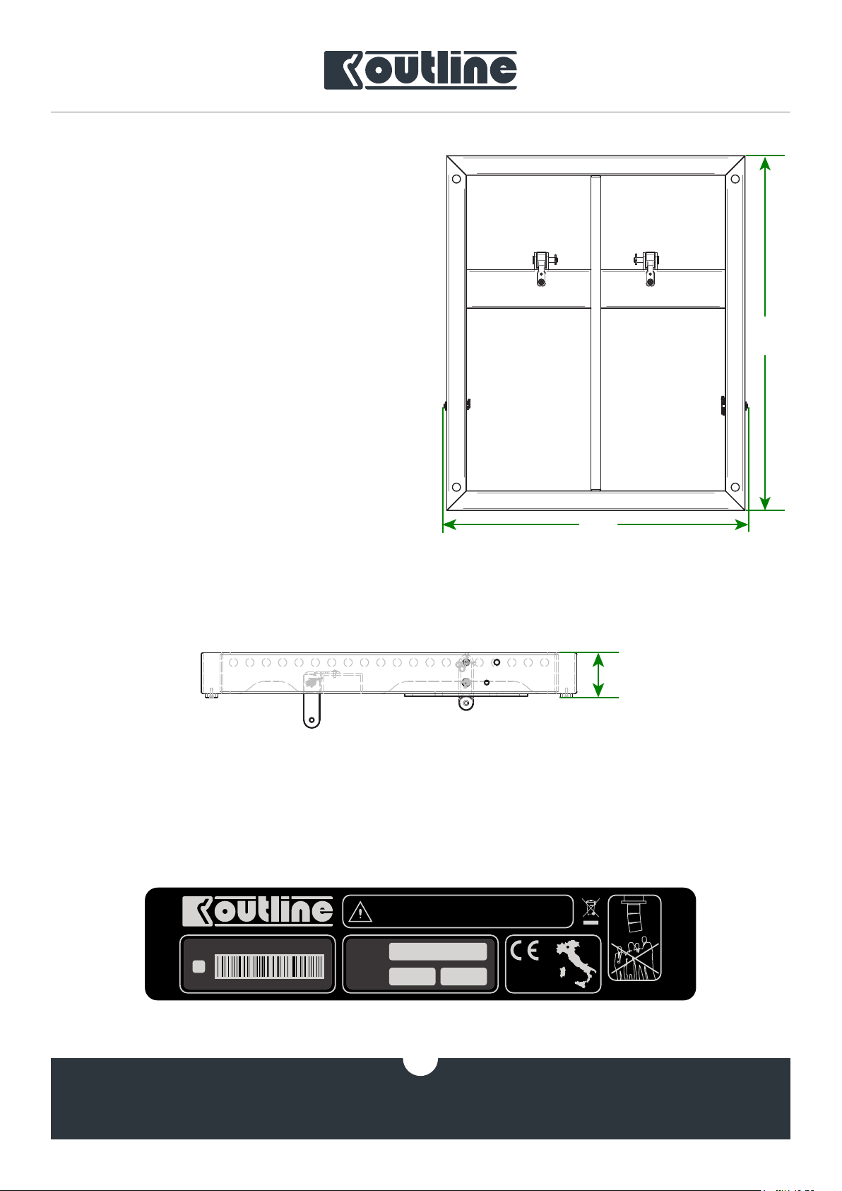
2.2. FRAME BAR SPECIFICATIONS
110
FRM1-AL630 Superfly/Mantas28
is a frame bar
approved and certified for these two line array elements that share the same integrated hardware.
Below you will find the specifications of the frame
bar:
• Weight…………………………….………………....... 28 kg
• Material.…………..... Ultra-resistant aluminium
• Width.......………………………………..………. 790 mm
• Length.....………………………………...……… 917 mm
• Height………………………………………..……. 110 mm
917
790
110
The maximum declared load is 630 kg, including the line array elements, their cables, spansets, shackles
and additional safety locks. It is necessary in any case to follow the parameters given in the chapter above and
respect the limits imposed by OpenArray2 in the design phase.
READ INSTRUCTIONS BEFORE USE.
DO NOT STAND OR WALK UNDER
THE SYSTEM WHEN IT IS FLOWN.
630 kg - 1388 lb
Designed and
manufactured
with pride in Italy
outline.it
SERIAL N°
TESTED
TESTED
MODEL: A FRM1-AL630
YEAR
S.N°: 000000000
CAUTION
MAX LOAD
MAX LOAD
WEIGHT
WEIGHT
21.5 kg 47.4 lb
5
OUTLINE S.R.L.
Via Leonardo da Vinci, 56
25020 Flero (Brescia) Italy
Tel.: +39 030.3581341
Fax +39 030.3580431
info@outline.it
www.outline.it
Page 6
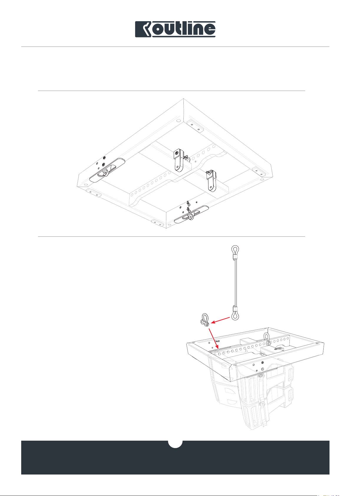
FRM1-AL630
is equipped with four solid rotatable hardware parts (two front and two rear ones), easy to
mount and fasten to the line array elements. Its load beam has 20 pick points for fastening the hoist(s), as
calculated by OpenArray2.
The shackle should be fastened to the pick point in-
dicated by the software.
In case common chain hoists are used, it coud be
of help to use a wire rope sling with thimbles to avoid
that the bag containing the chain leans upon the cluster causing chain lock or unwanted vertical displacement of the array.
It should be the authorized staff’s care to verify and
ensure the integrity and suitability of all additional rigging tools. Outline, besides providing advice, assumes
no responsibility for the choice of these tools. Furthermore, Outline considers itself unrelated to any
unauthorized modication of the mechanical parts
of the frame. Considering the high weights involved,
we remind you that these instruments must guarantee maximum safety under any circumstances (whith
their appropriate use as a necessary prerequisite).
OUTLINE S.R.L.
Via Leonardo da Vinci, 56
25020 Flero (Brescia) Italy
Tel.: +39 030.3581341
Fax +39 030.3580431
info@outline.it
6
www.outline.it
Page 7

2.3. INTEGRATED HARDWARE OF LINE ARRAY ELEMENTS
Similar to the frame bar hardware, the
Mantas28
elements also have a simple but very effi-
Superfly /
cient hardware structure. These hardware elements
are made of ultra-light aluminium and are designed,
approved and certified to support the established loads.
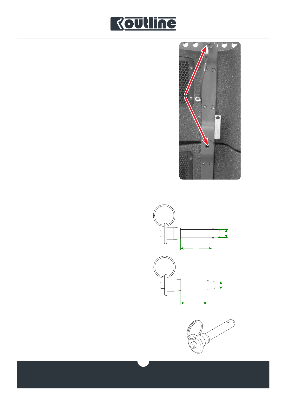
The sliding bars, inserted in the rails on the back
of the cabinets, are easy to adjust and allow a vertical
inclination from 0 ° to 7.5 ° with 0.5 ° steps (with the
addition of the 0.25 ° angle) between the elements.
In the lower part (fig. 1) of each rail there are 4 holes
for locking pins corresponding to the “groups” of angles illustrated next to the rail.
This allows a very precise pointing choice which addresses any type of need. Further details on their use
in chapter 4.
In the upper part (figure 2), each rail receives the bar
of the previous element or of the frame bar, presenting a hole (“Default”) dedicated to all the selectable
degrees with the exception of the 0.25 ° angle, for which the dedicated hole (called “0.25 ° ONLY”) should be
used. For the connection to the frame bar the “Default” hole is used.
OUTLINE S.R.L.
Via Leonardo da Vinci, 56
25020 Flero (Brescia) Italy
Tel.: +39 030.3581341
Fax +39 030.3580431
info@outline.it
figure 1
figure 2
7
www.outline.it
Page 8
The front of the cabinet (figure 3) has non-adju-
36
9.5
30
stable hardware parts on both sides, complementary
to the rear ones.
The example in Figure 3 shows a first element fastened to the frame and a second element ready to
be fastened. Learn more about the various steps in
Chapter 4.
2.4. LOCKING PINS
The locking pins on the back and front of the cabinets are practical and convenient to use, guaranteeing
maximum safety.
They are made of ultra-resistant steel and once inserted into the lock point the whole body of the line
array element remains stable mantaining the chosen
pointing angle. The pins chosen for
tas 28
the longer ones (
are of two types and differ only in their length:
BLC6BA14S
the rear hardware parts, while the shorter ones (
C6BA12S
) have been chosen for the front hardware
parts.
All the pins are fixed to the cabinet by means of a
lanyard, to avoid their loss.
Superfly
and
Man-
) have been chosen for
BL-
36
figure 3
9.5
item nr. BLC6BA14S
9.5
The specifications of the locking pins:
• Weight………………….....………….……………… 30 / 40 g
• Material.....………….............. Ultra-resistant steel
• Diameter (body)...……………………………...... 9.5 mm
• Depth (body).........……………….………..... 30 / 36 mm
OUTLINE S.R.L.
Via Leonardo da Vinci, 56
25020 Flero (Brescia) Italy
Tel.: +39 030.3581341
Fax +39 030.3580431
info@outline.it
item nr. BLC6BA12S
8
www.outline.it
Page 9

2.5. HARDWARE INSPECTION
It is of utmost importance to periodically check the
integrity of the entire structure of the hardware both
of the line array elements and of the frame bar.
Being these components placed under stress by
heavy weights, different places of use, continuous
transportation and more, they can be subject to damage in the long term, despite the excellent quality of
the materials.
Here below you will find some precautions to follow, at the discretion of the authorized staff:
1. Make sure there is no rust in the hardware or
locking pins. In case of rust use suitable and
certified products for its removal. The rust
could be deposited by other oxidized elements or due to the oxidation of the element itself.
In the first case, the integrity of the component
must be checked after removing the rust; in the
second case, if the rust is only superficial, it can
be removed; if in removing it you notice that it
goes in depth you have to replace the element;
4. Free the mechanical parts and the holes of the
hardware from any dust or other residues. This
will allow the correct insertion of the pins and
the right positioning of the hardware.
The inscriptions indicating the degrees of inclination are engraved in the hardware. This prevents any
cancellation, but in case of excessive corrosion for
other reasons, Outline can provide, if deemed appropriate, a replacement part and assistance.
All the hardware components are designed in compliance with the safety regulations in force following
in-depth studies of the Outline R&D department and
subsequent certification by specialized engineers, in
compliance with the laws based on the EEC / EU directives (chap. 1.2).
2. Check that the sliding bar of the rear hardware part remains in its rail (not above the “Rest
point” upwards and not more than at 0.25°
downwards). Otherwise the hardware part is
to be considered dangerous for any type of use
and, therefore, is to be replaced;
3. Check that the locking pins close correctly,
which means that the two steel balls come out
completely outside the locking pin body. It is
important to ensure the immobility of the pins
in the locking points;
OUTLINE S.R.L.
Via Leonardo da Vinci, 56
25020 Flero (Brescia) Italy
Tel.: +39 030.3581341
Fax +39 030.3580431
info@outline.it
9
www.outline.it
Page 10

3. OPEN ARRAY 2 - PRE-RIGGING
OpenArray2
is a software which helps the system
engineer to calculate and establish a first relationship
between the sound system and the venue.
Given the potential of this software for acoustic forecasts and the possibilities of creating projects of various types (which are not covered by this manual), it
will be possible to know precisely if the configuration
is feasible in relation to the model and the number of
elements of the arrays used, to the inclination of the
clusters, motor coupling points and all the necessary
data for the PA man for a correct rigging in the field.
figure 4 figure 5
Some of the data regarding arrays vary based on
the use of one (figure 4) or two motors (figure 5). Logically the use of more motors guarantees greater maneuverability (during the rigging phases) and stability
of the array.
OUTLINE S.R.L.
Via Leonardo da Vinci, 56
25020 Flero (Brescia) Italy
Tel.: +39 030.3581341
Fax +39 030.3580431
info@outline.it
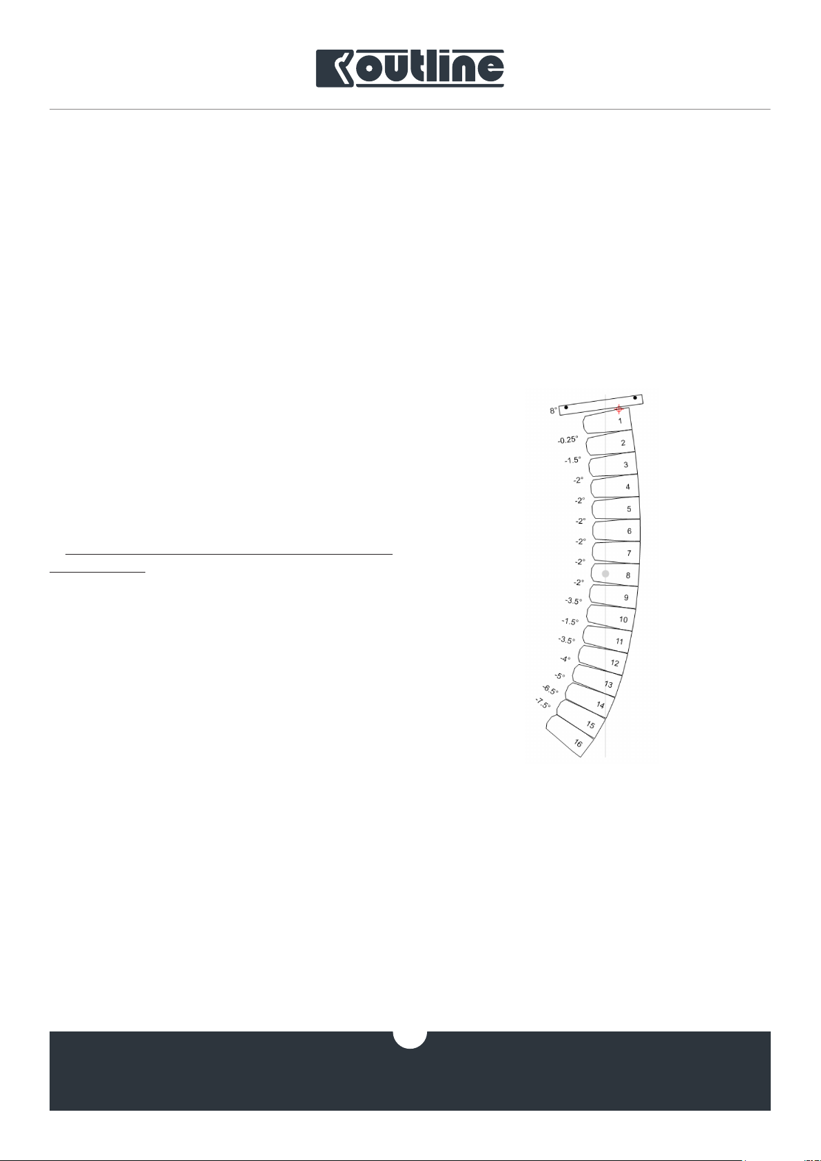
The angles selected for each element will be visible
in correspondence with the load bars in the relative
box on the OpenArray2 mechanic paper.
It is advisable to print and always carry the mechanic paper while doing the rigging.
10
www.outline.it
Page 11
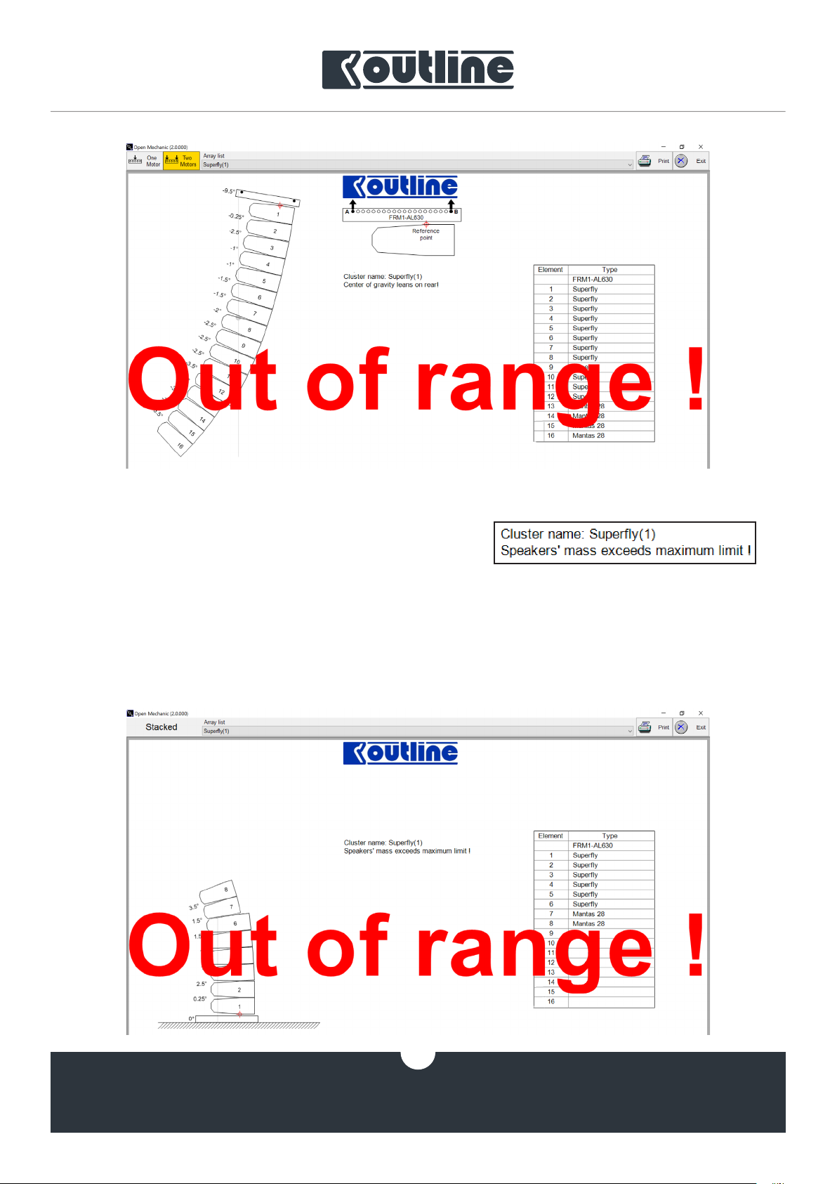
figure 6
Attention! When the software indicates the array is
out of range (as in figures 6 and 7), it could be necessary to:
• reassess the overall inclination of the array in
case the center of gravity is out of range;
• remove some line array elements because the
maximum limit weight has been exceeded;
figure 7
• both of the above.
These cases can also occur with ground stack con-
figurations (figure 8).
figure 8
11
OUTLINE S.R.L.
Via Leonardo da Vinci, 56
25020 Flero (Brescia) Italy
Tel.: +39 030.3581341
Fax +39 030.3580431
info@outline.it
www.outline.it
Page 12

Based on what stated in chap. 2.1, as in the example in figure 9, when setting 16 Superfly elements in
the project the final weight of the array (array mass)
will be different from the declared 608 kg (1340 lb).
This happens because the software sums also the
weight of the frame and the approximate weight of
other elements, such as cables, spansets, inclinometers and other small accessories, to the array weight.
Once all these points have been cleared, we can
proceed to the rigging execution phase.
figure 9
OUTLINE S.R.L.
Via Leonardo da Vinci, 56
25020 Flero (Brescia) Italy
Tel.: +39 030.3581341
Fax +39 030.3580431
info@outline.it
12
www.outline.it
Page 13

4. RIGGING PROCEDURE
4.1. PREPARATION
Once the necessary motors have been arranged
according to the project and the elements are out of
their flightcases, it is possible to proceed with the rigging.
However, we suggest you follow the steps described below to do everything with ease.
4.1.1. SPLAY ANGLES
Pre-set the splay angles between the array elements in pairs, according to OpenArray2 project instructions, while still positioned on their trolleys:
1. unlock the sliding bars (figure 11);
figure 10
figure 11
2. position the sliding bars aligning the chosen
degree point with the marker (white line) on the
rails containing them (figures 12 - 13);
figure 12 figure 13
OUTLINE S.R.L.
Via Leonardo da Vinci, 56
25020 Flero (Brescia) Italy
Tel.: +39 030.3581341
Fax +39 030.3580431
info@outline.it
13
www.outline.it
Page 14

3. lock the bars with the locking pins using one of
the corresponding holes, according to the chosen degree (figure 14);
figure 14
4. align the bars with the rails of the next array
element and fasten them with the locking pin in
the “Default” position if you’ve chosen the degree value between 0° and 7.5°, or in the “0.25°
ONLY” position if the 0.25° value has been chosen (figures 2 and 15);
5. once the angles for each couple of line array
elements are ready and put in order in which
they are to be flown, it is possible to proceed
with the installation of the frame bar.
OUTLINE S.R.L.
Via Leonardo da Vinci, 56
25020 Flero (Brescia) Italy
Tel.: +39 030.3581341
Fax +39 030.3580431
info@outline.it
figure 15
14
www.outline.it
Page 15
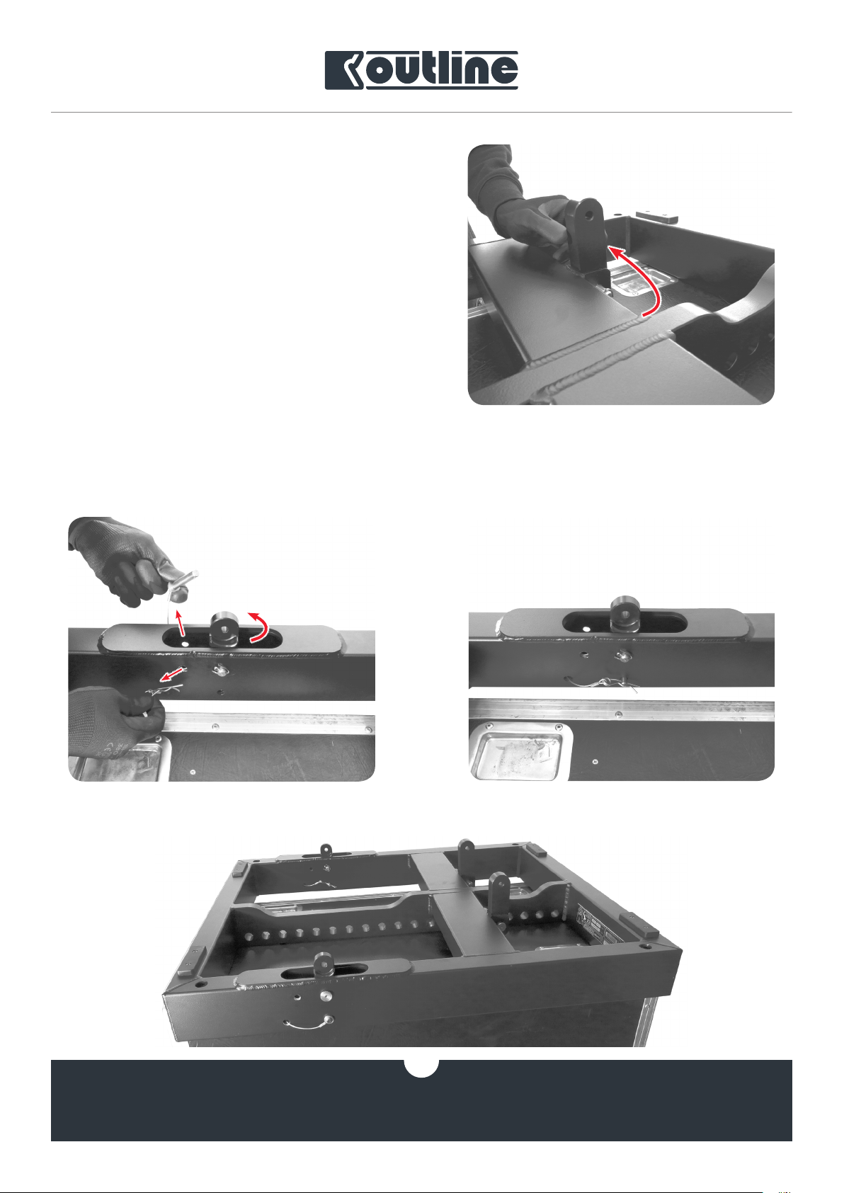
4.1.2. PREPARATION OF THE FRAME BAR
It is advisable to prepare the frame immediately to
be flown together with the first two elements of the
array, to make the job easier for the staff:
1. free the rear hardware parts of the frame by
simply lifting the movable bar that will be triggered, remaining stationary thanks to the automatic locking system (figure 16);
figure 16
2. remove the safety pins from the front locking
points and free the bar that will come out rotating by itself (figure 17);
3. reinsert the locking pin and its forelock to keep
the bar in place (figure 18);
figure 18figure 17
OUTLINE S.R.L.
Via Leonardo da Vinci, 56
25020 Flero (Brescia) Italy
Tel.: +39 030.3581341
Fax +39 030.3580431
info@outline.it
figure 19
15
www.outline.it
Page 16
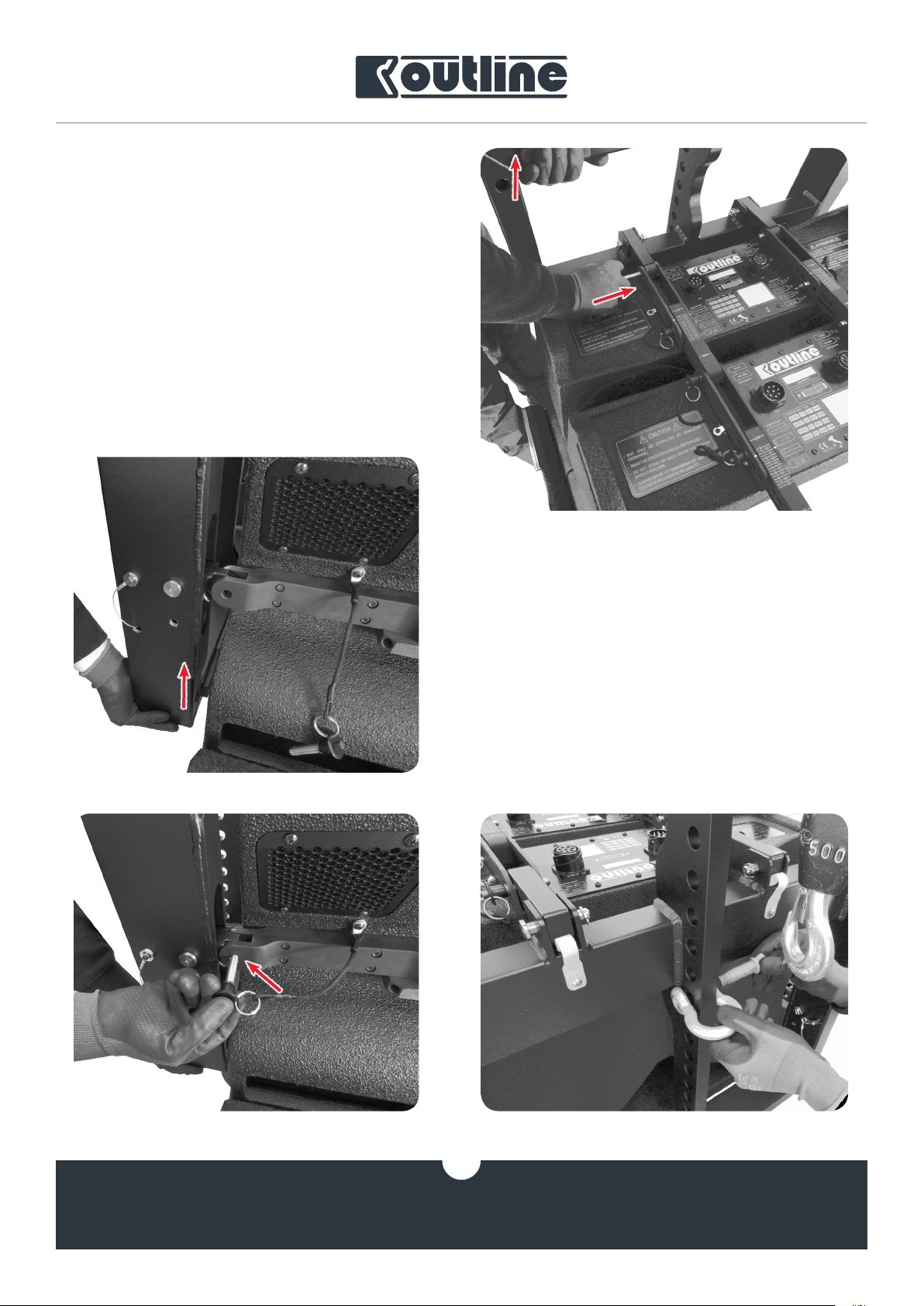
4. align the rear hardware parts of the frame with
the rails of the fist line array element and lock
with the pins in the “Default” position. To simplify the procedure it could be of help to lift the
frame bar with one hand, keeping it steady with
a foot, and insert the pin with the other hand
(figure 20).
figure 20
5. perform the same procedure for the front hardware parts of the frame, helping yourself with
one hand to align the parts (figures 21 and 22);
OUTLINE S.R.L.
Via Leonardo da Vinci, 56
25020 Flero (Brescia) Italy
6. fix the shackles to the motor coupling points as
calculated by
figure 21
figure 22 figure 23
OpenArray2
16
Tel.: +39 030.3581341
Fax +39 030.3580431
info@outline.it
www.outline.it
(figure 23);
Page 17
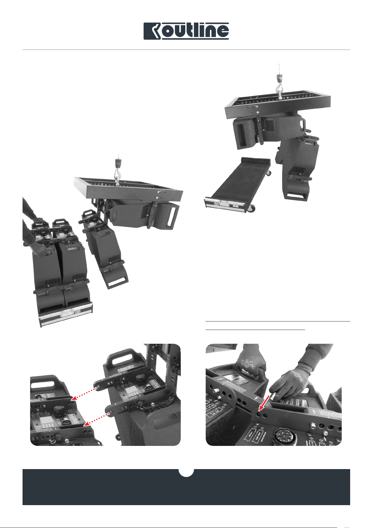
4.2. ASSEMBLING
Once the preparation phases have been completed, the array can be lifted starting with the first two
elements and then adding the remaining pairs, integrating any supplementary accessories (spansets,
cables, safety locks etc. - chap. 4.3):
1. lift the first two elements already fastened to
the frame and the hoist, keeping the front hardware parts of the second element free (this
will make the following step easier - figure 24);
figure 24
figure 25
2. align (figures 25 and 26) and fasten (figure 27)
the rear hardware parts of the last hanging
element to those of the first element of the following couple, holding the element by its handles to keep the array in place;
All these procedures are to be performed in the
presence of at least two persons.
OUTLINE S.R.L.
Via Leonardo da Vinci, 56
25020 Flero (Brescia) Italy
figure 26 figure 27
17
Tel.: +39 030.3581341
Fax +39 030.3580431
info@outline.it
www.outline.it
Page 18
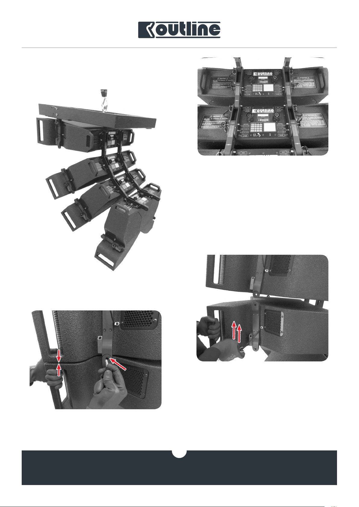
3. using the hoist(s), lift the array from the trolley at a suitable height to simplify the following
procedure (figure 29);
figure 28
4. at this point, fasten the front hardware parts
of the first three elements that are now flown.
Help yourself with both hands to lift the element as shown in figure 30, to be able to insert
the locking pin in the hole (figure 31). Leave out
the front hardware parts of the last element (figure 32).
figure 29
figure 31
figure 30
18
OUTLINE S.R.L.
Via Leonardo da Vinci, 56
25020 Flero (Brescia) Italy
Tel.: +39 030.3581341
Fax +39 030.3580431
info@outline.it
www.outline.it
Page 19

4.3. INTERMEDIATE PHASE
When the first four elements are flown, before continuing it could be necessary to add the following accessories:
1. a spanset for rigging the cables (with a shackle
or simply knotting it to the frame) (figure 33);
2. a security rope attached with a shackle, keep
ing some distance from the hoist coupling
shackle (figura 33);
3. if used, an inclinometer to be applied to the
front part of the frame, centered respect to the
array’s axis and fixed steadily;
figure 33
4.3.1. RIGGING THE CABLES
After having attached the spanset as described
above, depending on the quantity of the line array elements, arrange the cables as follows:
1. pass the first cable through the spanset knot
and plug it into the first element (figure 34);
2. plug the three link cables;
3. prepare the other cables to pass them through
the spanset at the length approximately equal
to the distance from the fifth (and ninth) element
4. pass through the spanset the remaining cables
of the chain hoist(s), inclinometer and others
5. moderately tighten the knot of the spanset to
keep everything in place
Attention: it is advisable to leave the right length
of the cables to prevent them from being tightened
excessively.
figure 32
figure 34
In case only one chain hoist is used, the cables
influence the array’s inclination depending on their
overall weight (and consequently on their height from
the ground). It is advisable to consider these variables
and compensate them, if possible.
19
OUTLINE S.R.L.
Via Leonardo da Vinci, 56
25020 Flero (Brescia) Italy
Tel.: +39 030.3581341
Fax +39 030.3580431
info@outline.it
www.outline.it
Page 20

4.4. FINAL PHASE
Proceed with flying the remaining elements till you
complete the array, making sure that all the locking
pins are positioned correctly.
The last steps to follow are:
1. tie the cables together to create a well-ordered
bundle as the array goes up;
2. once reached the necessary height, fix the array
with the ropes to regulate the vertical and horizontal inclination according to the project;
3. fix the safety lock if used.
The same steps, with the only difference in the audio connector on the rear panel of the loudspeaker,
are to be followed both for Superfly and for Mantas 28.
The total compatibility between their hardware parts (figure 35) allows different configurations as long
as they are approved by OpenArray2 project.
figure 35
OUTLINE S.R.L.
Via Leonardo da Vinci, 56
25020 Flero (Brescia) Italy
Tel.: +39 030.3581341
Fax +39 030.3580431
info@outline.it
figure 36
20
www.outline.it
Page 21

4.5. DERIGGING
For the reverse process the steps to follow are
exactly the opposite to those just described.
After removing the ropes and the secure lock, when
starting to lower the array, it can be useful to consider
the following points:
1. place the trolleys under the array so that the
elements can be put on them in couples and remove the locking pins from the front hardware
parts of the last three elements, maintaining
the rear pins in their position (figure 37);
2. continue to lower the array with the hoists and
use the handles to couple the elements with the
trolley (figure 38);
3. when the first two elements are on the trolley,
release the rear pins of the second element,
with the third element still hanging (figure 39);
4. repeat the procedure for each couple of elements, unplugging the cables and removing
any other accessory;
5. uncouple the frame bar from the chain hoists
together with the last two array elements and
remove the locking pins.
It is highly recommended to put the hardware both
of the frame bar and of the line array element in the
“REST” position before closing the flight cases to preserve their integrity during transport.
figure 37
OUTLINE S.R.L.
Via Leonardo da Vinci, 56
25020 Flero (Brescia) Italy
figure 38 figure 39
21
Tel.: +39 030.3581341
Fax +39 030.3580431
info@outline.it
www.outline.it
Page 22

4.6. GROUND STACK CONFIGURATION
For a stack array configuration it is necessary to
follow a procedure where the frame bar and the array
elements are literally upside down and their maneuverability is reduced. Always keeping in mind the indications given by the OpenArray2 software, proceed
as follows:
1. prepare the frame bar with the released hardware and looking upwards (figure 40);
figure 40
figure 41
3. posizionare il frame montato a terra, predisponendo il puntamento orizzontale prima di collocare qualsiasi elemento che ne renderebbe
difficile lo spostamento (figura 43);
2. insert the “foot 01” accessory (figure 41) in the
rear holes (figure 42) and adjust its height. In
case the chosen element is
Mantas 28
, it will
be however possible to choose both positions
for the feet (front and rear). It is not possible to
choose the front position when using
Superfly
(the first element should be aimed downwards).
OUTLINE S.R.L.
Via Leonardo da Vinci, 56
25020 Flero (Brescia) Italy
figure 43
Tel.: +39 030.3581341
Fax +39 030.3580431
info@outline.it
figure 42
22
www.outline.it
Page 23

4. mount the element upon the frame upside
down (180°) to have the rear hardware looking
upwards;
5. secure the front hardware parts and then the
rear ones, remembering that the whole procedure will be the same but to be done on the
contrary (figure 44). This means that it will be
possible to choose the inclination once the element has been stacked and the front hardware has been locked (the higher the grade, the
higher will be the inclination of the upper element) (figure 45);
figure 44
6. repeat the procedure for all the elements according to the
OpenArray2
project, while also
doing the cabling (figure 46);
figure 45
7. perform the disassembly exactly on the contrary respect to the assembly procedure.
OUTLINE S.R.L.
Via Leonardo da Vinci, 56
25020 Flero (Brescia) Italy
Tel.: +39 030.3581341
Fax +39 030.3580431
info@outline.it
figure 46
23
www.outline.it
Page 24

5. TRANSPORT AND STORAGE
When transporting the system it is advisable:
• to move the elements couples as shown in figure 48 to avoid accidents (figure 47)
• although resistant, avoid placing any excessive
loads on the closed flight cases containing the
array elements;
• to lock the loads in the chosen means of transport.
Once in the warehouse, store your
Mantas 28
in their flight cases, keep them in covered
Superfly
and
and not very humid places, away from heat sources.
figure 47
OUTLINE S.R.L.
Via Leonardo da Vinci, 56
25020 Flero (Brescia) Italy
Tel.: +39 030.3581341
Fax +39 030.3580431
info@outline.it
figure 48
24
www.outline.it
Page 25

NOTES
OUTLINE S.R.L.
Via Leonardo da Vinci, 56
25020 Flero (Brescia) Italy
Tel.: +39 030.3581341
Fax +39 030.3580431
info@outline.it
25
www.outline.it
Page 26

NOTES
OUTLINE S.R.L.
Via Leonardo da Vinci, 56
25020 Flero (Brescia) Italy
Tel.: +39 030.3581341
Fax +39 030.3580431
info@outline.it
26
www.outline.it
Page 27

NOTES
OUTLINE S.R.L.
Via Leonardo da Vinci, 56
25020 Flero (Brescia) Italy
Tel.: +39 030.3581341
Fax +39 030.3580431
info@outline.it
27
www.outline.it
Page 28

Outline carries out on-going research for product improvement. New materials, manufacturing methods
and design upgrades are introduced to existing products without prior notice as a routine result of this philosophy. For this reason, any current Outline product may differ is some aspect from its description, but will
always equal or exceed the original design specifications unless otherwise stated.
© Outline 2019
Operating manual product code: Z RMSUPERFLY-MANTAS28
Release: 20190326
Printed in Italy
 Loading...