

Page 1
DELIVERING THE TRUE AUDIENCE EXPERIENCE
MANUALE ISTRUZIONI
OPERATING MANUAL
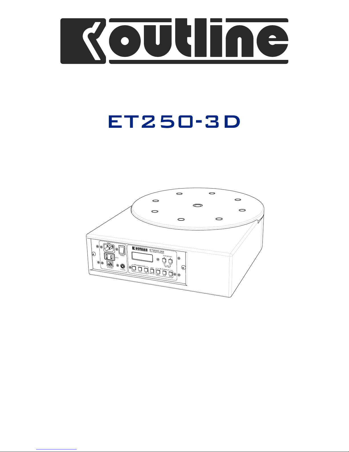
ELECTRONIC TURNTABLE
Page 2
Outline s.r.l. - Via Leonardo da Vinci, 56 - 25020 Flero (Brescia) - Italy
Tel. +39-30-3581341 Fax +39-30-3580431 — Web Site: www.outline.it — E-Mail: info@outline.it
2
DELIVERING THE TRUE AUDIENCE EXPERIENCE
CONFORMITÀ *
*Comunità Europea
Tutte le apparecchiature elettroniche ed elettroacustiche
Outline rispondono ai requisiti indicati dalle direttive CEE:
Sicurezza
73/23 e successiva modificazione 93/68 art. 13
Compatibilità elettromagnetica
89/336 e successiva modificazione 93/68 Art. 5.
Gli standard applicati sono:
Sicurezza: EN 60065
Prescrizioni di sicurezza per apparecchi elettronici e loro accessori
collegati alla rete per uso domestico e analogo uso generale.
Compatibilità elettromagnetica per app. audio
Emissioni - Armoniche: EN 61000-3-2
- Fluttuazioni di tensione: EN 61000-3-3
- Interferenze radio: EN 55013
Immunità: EN 55020
* CONFORMITY
*European Community
All the Outline electroacoustic and electronic devices are in
accordance with the objects stated by below CEE directives:
Safety
73/23 and following modification 93/68 Art. 13
Electromagnetic compatibility
89/336 and following modification 93/68 Art. 5
Standards applied:
Safety: EN 60065
Safety requirements for mains operated electronic and related
apparatus for household and similar general use.
Electromagnetic compatibility audio equip.
Emissions - Harmonics: EN 61000-3-2
- Voltage fluctuations: EN 61000-3-3
- Radio interferences: EN 55013
Immunity: EN 55020
Onde evitare rischi per la propria e per l’altrui sicurezza,
nonché l’invalidazione della garanzia, si raccomanda di
leggere, nella sezione qui esposta, i consigli per un buon
utilizzo del prodotto.
· Non esporre l’apparecchio alla pioggia o ad elevata umidità.
· Proteggere l’apparecchio dalla penetrazione accidentale di
liquidi o di oggetti solidi; se questo dovesse avvenire, non
utilizzare più l’apparecchio e rivolgersi quanto prima ad
OUTLINE o a personale competente.
· Collegare l'apparecchio verificando SEMPRE il contatto di
messa a terra come richiesto dalle normative.
· Se il cavo di collegamento originale presentasse segni di
usura o di deterioramento, sostituirlo con uno analogo.
· Eseguire i collegamenti in modo ordinato limitarne l'accesso
o l'avvicinamento solo al personale addetto.
· L’apparecchio non deve essere aperto e/o riparato se non
da personale competente.
· Per qualsiasi esigenza o informazione di natura tecnica
rivolgersi ad OUTLINE o a personale autorizzato.
· L'apparecchiatura è dedicata alla movimentazione di
oggetti che possono essere pesanti e/o ingombranti. Per
questo motivo il suo utilizzo deve essere effettuato sotto
la supervisione di personale competente.
In order to avoid risks for the user's and other people's
safety, as well as annulling the warranty, it is advisable to
read the suggestions in this section for correct use of the
product.
· Do not expose the unit to rain or use it in locations with a
high humidity level.
· Ensure that no liquids or solid objects accidentally enter the
unit; should this occur, stop using the unit and contact
OUTLINE or specialist staff.
· When connecting the unit, ALWAYS check ground connection
as required by technical and safety norms.
· If the original connector cable is worn or damaged, it must
be replaced with another of the same type (in perfect
condition).
· Carry out connections in an orderly manner, only allowing
access to experienced specialist staff.
· The unit must only be opened and/or repaired by specialist
staff.
· For any requirements of a technical nature, contact
OUTLINE or authorized staff.
· The unit is dedicated to moving heavy or bulk objects.
For this reason, it must be used under the supervision of
experienced personnel.
NORME DI SICUREZZA / SAFETY REGULATIONS
SMALTIMENTO RIFIUTI / DISPOSAL OF WASTE MATERIALS
L'apparecchio è stato progettato e prodotto con
materiali e componenti di qualità elevata riciclabili e
riutilizzabili. Il simbolo del cassonetto su ruote barrato
indica che l'apparecchio è conforme alla Direttiva
Europe a 2002/96/CE e successiva modifica
2003/108/CE. Informarsi sui regolamenti locali in merito alla
raccolta differenziata di prodotti elettronici ed elettrici.
Attenersi ai regolamenti locali ed evitare di smaltire i vecchi
apparecchi come normali rifiuti domestici. Si ricorda che un
corretto smaltimento dell'apparecchio aiuta a salvaguardare la
salute e l'ambiente.
Your product is designed and manufactured with highly
quality material and components, which can be recycled
and reused. When this crossed-out wheeled bin symbol is
attached to a product, it means the product is covered by
the European Directive 2002/96/EC and subsequent
amendment 2003/108/EC. Please inform yourself about the local
separate collection system for electrical and electronic products.
Please act according to your local rules and do not dispose your
old products with your normal household waste. The correct
disposal of your old product will help prevent potential negative
consequences for the environment and human health.
Page 3
Outline s.r.l. - Via Leonardo da Vinci, 56 - 25020 Flero (Brescia) - Italy
Tel. +39-30-3581341 Fax +39-30-3580431 — Web Site: www.outline.it — E-Mail: info@outline.it
3
Electronic Turntable
ET250-3D
Dopo il grande successo delle versioni precedenti (iniziato nel
lontano 1990), nasce la nuova tavola rotante ET250-3D Outline.
ET250-3D vede la luce dopo anni di studi e test che le
consentono di garantire eccellenti prestazioni.
La robustezza meccanica fa della tavola rotante ET250-3D un
autentico “mulo” capace di sopportare notevoli carichi.
L’utilizzo combinato di due unità, affiancato da un’adeguata
struttura (vedi esempio a pagina 14 di questo manuale)
consente di ottenere una rotazione di tipo tridimensionale,
particolarmente utile, per esempio, ai costruttori di diffusori
acustici.
L’unità di controllo a microprocessore garantisce la massima
precisione e, grazie all’interfaccia di rete conforme allo
standard TCP/IP, consente il completo controllo da PC. A tal
scopo Outline fornisce un software dedicato che può
controllare fino a due unità gestendone il movimento
sincronizzato. Nel pacchetto è incluso un controllo di tipo COM
ActiveX Server a disposizione degli utenti che desiderino
sincronizzare il proprio software con quello di controllo.
A richiesta Outline distribuisce anche una DLL dedicata
(Dynamic Link Library) per gli sviluppatori di software.
Per la compatibilità con alcune schede di misura presenti sul
mercato, la tavola rotante ET250-3D è dotata di una porta
Input/Output basata su segnali TTL attraverso la quale è
possibile inviare all’unità il comando di rotazione e ricevere un
impulso di ritorno a rotazione ultimata.
L’elettronica di controllo, normalmente integrata nel corpo
della tavola rotante, può essere estratta e posizionata a
distanza con una semplice prolunga.
After the great success of the previous versions (which dated
back to far-off 1990), here is the new Outline ET250-3D
turntable. The ET250-3D is the result of years of study and tests
that enable it to guarantee excellent performance.
The mechanical sturdiness makes the ET250-3D turntable a real
rugged tool able to support remarkable loads. The combined
use of two units, backed up by a suitable structure (see the
example on page 14 of this manual), enables to obtain threedimensional rotation, which is particularly useful to
loudspeaker enclosure manufacturers, for example.
The microprocessor-based control unit guarantees utmost
precision and, thanks to the network interface in compliance
with TCP/IP standard, enables the unit to be completely
controlled via PC. For this purpose, Outline supplies dedicated
software that can control up to two units, commanding their
synchronized movement. The package includes a COM ActiveX
Server type control at the disposal of users who wish to
synchronize their own software with the unit's control
software.
On request, Outline also provides a dedicated DLL (Dynamic
Link Library) for software developers.
For compatibility with some measurement cards on the
market, the ET250-3D turntable is equipped with an
Input/Output port based on TTL signals through which it is
possible to send the unit the rotation command and receive a
return pulse when rotation ends.
The control electronics, normally lodged in the body of the
turntable, can be removed and positioned at a distance with a
normal extension cable.
Page 4
Outline s.r.l. - Via Leonardo da Vinci, 56 - 25020 Flero (Brescia) - Italy
Tel. +39-30-3581341 Fax +39-30-3580431 — Web Site: www.outline.it — E-Mail: info@outline.it
4
DELIVERING THE TRUE AUDIENCE EXPERIENCE
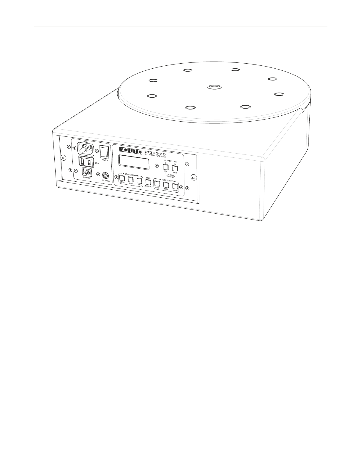
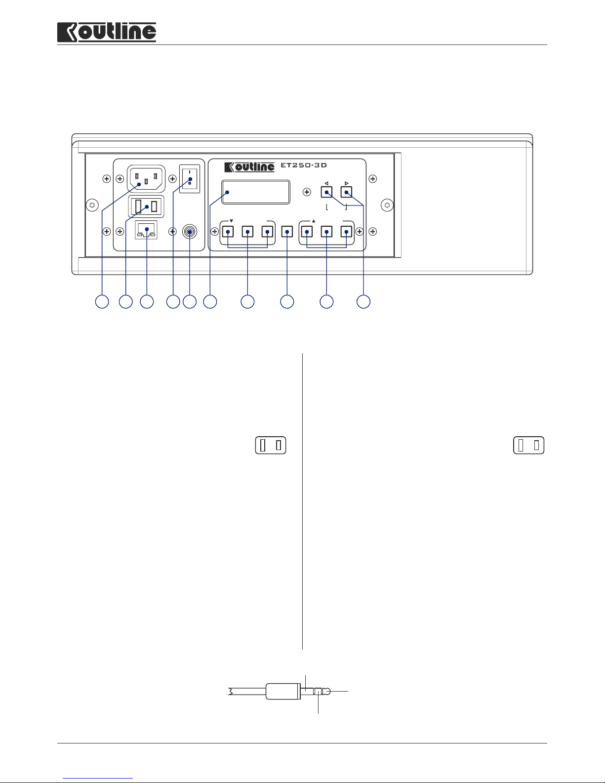
PANNELLO ANTERIORE / FRONT PANEL
1) MAINS: mains power connector.
Connect using the appropriate cable supplied.
Its switch-mode circuitry enables the unit to be used with
any voltage between 90 Vac and 250 Vac.
2) DC IN: connector for powering the unit with a battery
(requires continuous voltage of between 12 and 15 Volts).
Connect using the appropriate cable supplied,
making certain to respect polarity.
When the unit is powered with a DC supply, the
ON/OF switch [4] is disabled and the unit come on
immediately.
Do NOT use this type of power supply simultaneously with
the mains power supply [1].
3) ETHERNET: Rj45 connector for PC connection.
4) ON/OFF switch: this switch can only be used when the unit
is powered with the mains power supply [1].
5) TTL SYNC: mini jack connector for connection with some
measurement cards. The ET250-3D unit moves forward
(degrees increase) by the preset step (see point [10]) when
it receives a TTL pulse on its input.
Once rotation is finished, after a preset delay (see point
[10]), it sends a TTL pulse.
6) 4 digit Display for displaying the degrees of rotation.
1) MAINS: connettore per l'alimentazione da rete.
Connettere utilizzando l'apposito cavo in dotazione.
La circuitazione di tipo switch mode consente l’utilizzo
dell’apparecchio con qualsiasi tensione di rete compresa
tra i 90 VAC e i 250 VAC.
2) DC IN: connettore per l’alimentazione dell’apparecchio da
batteria (richiede una tensione continua tra i 12 V e i 15 V).
Connettere utilizzando l’apposito cavo in
dotazione facendo attenzione a rispettare le
polarità.
Quando l’apparecchio è alimentato a tensione continua,
l’interruttore di accensione [4] è disabilitato e l’apparecchio
si accende immediatamente. Non utilizzare questo tipo di
alimentazione in contemporanea a quella di rete [1].
3) ETHERNET: connettore Rj45 per la connessione con il PC
4) Interruttore di accensione. Questo interruttore funziona
solo quando l’unità è alimentata con tensione di rete [1].
5) TTL SYNC: connettore mini jack per il collegamento con
alcune schede di misura. L’unità ET250-3D compie un
movimento in avanti (incremento dei gradi) dello step
preimpostato (vedi punto [10]) quando riceve un impulso
TTL in ingresso. A sua volta, terminata la rotazione, dopo un
ritardo preimpostato (vedi punto [10]), presenta in uscita
un impulso TTL.
6) Display a 4 cifre per la visualizzazione dei gradi di rotazione.
ZERO STEP MAN.
ZERO SET
MAN. STEP
ZERO
ETHERNET
STEP SETTING
TTL DELAY
SETTING
ESC SAVE
MAINS
TTL SYNC
POWER
DC IN
DEGREES UPDEGREES DOWN
STOP
ELECTRONIC TURNTABLE
10987654321
+
+
-
GROUND
TTL INPUT
TTL OUTPUT
Page 5

Outline s.r.l. - Via Leonardo da Vinci, 56 - 25020 Flero (Brescia) - Italy
Tel. +39-30-3581341 Fax +39-30-3580431 — Web Site: www.outline.it — E-Mail: info@outline.it
5
Electronic Turntable
ET250-3D
7) DEGREES DOWN: buttons for rotating the turntable
backwards (degrees decrease).
ZERO: the turntable reaches the position of 0 degrees.
STEP: the turntable rotates by the number of degrees
preset using the buttons [10].
MANUAL: the turntable rotates by 0.5 degrees, which is the
minimum movement.
8) STOP/ZERO SET: this button has a dual function.
When pressed normally, immediately stops the base during
rotation.
When pressed and held down for more than 2 seconds, sets
the current position as 0 degrees, resetting the display.
9) DEGREES UP: buttons for rotating the turntable in forward
(degrees increase).
ZERO: the turntable reaches the position of 0 degrees.
STEP: the turntable rotates by the number of degrees
preset using the buttons [10].
MANUAL: the turntable rotates by 0.5 degrees, which is the
minimum movement.
10) STEP SETTING: these buttons have a dual function.
Normally use to set the movement step of the turntable
(from a minimum of 0.5 degrees to a maximum of 359.5
degrees).
Pressing the two buttons together gives access to the
setting of the delay for the output of the TTL pulse when
rotation finishes:
Ÿ Pressing the MAN. buttons increases or decreases the
delay by 1 ms.
Ÿ Pressing the STEP buttons increases or decreases the
delay by 100 ms.
Ÿ Pressing the SAVE button stores the new value set for the
delay.
Ÿ Press the ESC button to exit delay modification
procedure, restoring the value already stored.
7) DEGREES DOWN: pulsanti per la rotazione della tavola
nella direzione di decremento dei gradi.
ZERO: la tavola raggiunge la posizione 0 gradi.
STEP: la tavola ruota della quantità di gradi preimpostata
mediante i pulsanti [10].
MANUAL: la tavola ruota di 0.5 gradi che corrispondono al
minimo movimento.
8) STOP/ZERO SET: questo pulsante ha una doppia funzione.
Premuto normalmente ferma immediatamente la base
durante la rotazione.
Tenuto premuto per più di 2 secondi, imposta la posizione
corrente come posizione 0 gradi, azzerando il display.
9) DEGREES UP: pulsanti per la rotazione della tavola nella
direzione di incremento dei gradi.
ZERO: la tavola raggiunge la posizione 0 gradi.
STEP: la tavola ruota della quantità di gradi preimpostata
mediante i pulsanti [10].
MANUAL: la tavola ruota di 0.5 gradi che corrispondono al
minimo movimento.
10) STEP SETTING: questi pulsanti hanno una doppia funzione.
Normalmente servono per impostare lo step di movimento
della tavola (da un minimo di 0.5 gradi ad un massimo di
359.5 gradi).
Premendo contemporaneamente i due pulsanti si accede
all’impostazione del ritardo per l’uscita dell’impulso TTL al
termine della rotazione:
Ÿ Premendo i pulsanti MAN. si incrementa o decrementa il
ritardo di 1 ms.
Ÿ Premendo i pulsanti STEP si incrementa o decrementa il
ritardo di 100 ms
Ÿ Premendo il pulsante SAVE viene salvato il nuovo valore
impostato per il ritardo.
Ÿ Premendo il pulsante ESC si abbandona la modifica del
valore del ritardo, ripristinando quello già memorizzato.
Page 6

Outline s.r.l. - Via Leonardo da Vinci, 56 - 25020 Flero (Brescia) - Italy
Tel. +39-30-3581341 Fax +39-30-3580431 — Web Site: www.outline.it — E-Mail: info@outline.it
6
DELIVERING THE TRUE AUDIENCE EXPERIENCE
DIMENSIONI MECCANICHE / MOUNTING DIMENSIONS
DISIMBALLAGGIO / UNPACKING
Dopo il disinballaggio si prega di verificare con la massima
attenzione la presenza di eventuali danni. In caso affermativo
si prega di avvisare il rivenditore.
Si consiglia di conservare l’imballo da utilizzare in caso di
trasporto dell’unità in un secondo momento.
L’unità Outline ET250-3D viene fornita con i seguenti accessori:
· N°1 cavo di alimentazione da rete (AC)
· N°1 cavo per la connessione alla batteria elettrica (DC)
· N°1 connettore Combicon 9 poli maschio e N°1 connettore
Combicon 9 poli femmina
· N°1 CD con il software
· Certificato di garanzia
· Questo manuale
After unpacking the unit, check very carefully for any damage.
If any damage is found, please notify your dealer .
It is advisable to keep the packaging for use in the event of the
unit being transported in the future.
The Outline ET250-3D unit is supplied with the following
accessories:
· 1 AC mains power cable
· 1 cable for connecting the DC battery
· 1 9-pin male Combicon connector and 1 9-pin female
Combicon connector
· 1 software CD
· Warranty certificate
· Operating manual
455 mm
350 mm
107 mm
BOTTOM (FIXED)TOP (ROTATING)
8 M8 FIXING HOLES (x 25 mm MAX) ON 244 mm DIAMETER
1 M20x20 ONLY FOR LOAD COMPENSATION
N° 8 FORI DI FISSAGGIO M8 (x 25 mm MAX) SUL ø 244 mm
N° 1 FORO M20x20 SOLO PER COMPENSAZIONE DEL CARICO
8 M8 FIXING HOLES (x 25 mm MAX) ON 244 mm DIAMETER
1 M20x20 ONLY FOR LOAD COMPENSATION
N° 8 FORI DI FISSAGGIO M8 (x 25 mm MAX) SUL ø 244 mm
N° 1 FORO M20x20 SOLO PER COMPENSAZIONE DEL CARICO
Page 7

Outline s.r.l. - Via Leonardo da Vinci, 56 - 25020 Flero (Brescia) - Italy
Tel. +39-30-3581341 Fax +39-30-3580431 — Web Site: www.outline.it — E-Mail: info@outline.it
7
Electronic Turntable
ET250-3D
INSTALLAZIONE / INSTALLATION
MONTAGGIO
La tavola rotante Outline ET250-3D è stata progettata per
l’utilizzo sia in piano che verticale.
UTILIZZO ORIZZONTALE
La tavola rotante è stata testata per sopportare un carico
assiale di 1500 kg. Predisporre una adeguato supporto in piano
per garantire un buon funzionamento dell’apparecchio ed
evitarne la rottura.
UTILIZZO VERTICALE
La tavola rotante è stata testata per sopportare un carico
radiale massimo di 350 kg, con un momento flettente di 50kgm
ed un momento torcente di 25 kg m. È quindi necessario
verificare i carichi che vengono applicati, tenendo conto della
distanza del baricentro del carico dal piano di appoggio della
tavola.
Utilizzare la seguenti formule:
Max momento flettente = 50kg / D (con limite di 350 kg)
Max momento torcente = 25kg / D (con limite di 350 kg)
dove D = distanza in metri
IL COSTRUTTORE DECLINA OGNI RESPONSABILITÀ PER
EV ENT U AL I D A NN I C AUS AT I D A US I I MPR OPR I
DELL’APPARECCHIO O DAL MANCATO RISPETTO DEI
PARAMETRI DICHIARATI.
Max 350 kg
(770 lb)
Max 100 kg
(220 lb)
Max 50 kg
(110 lb)
Max 350 kg
(770 lb)
Max 50 kg
(110 lb)
Max 25 kg
(55 lb)
MOUNTING
The Outline ET250-3D turntable was designed horizontal and
vertical use.
HORIZONTAL USE
The turntable has been tested to support an axial load of
1,500 kg (3,300 lb). Prepare a suitable level support to
ensure good operation of the unit and avoid it being
damaged.
VERTICAL USE
The turntable has been tested to support a maximum radial
load of 350 kg, with a bending moment of 50 kg/m and a torque
of 25 kg/m. It is therefore necessary to check the loads that are
applied, taking into consideration the distance of the centre of
gravity of the load from the turntable platter.
Use the following formulae:
Max bending moment = 50kg / D (with a limit of 350 kg)
Max torque = 25kg / D (with a limit of 350 kg)
where D = distance in meters
TH E M AN U FA CTU R ER D E CLI NES ANY AN D AL L
RESPONSIBILITY FOR ANY DAMAGE CAUSED BY INCORRECT
USE OF THE UNIT OR FAILURE TO COMPLY WITH THE
DECLARED PARAMETERS.
Page 8

8
Outline s.r.l. - Via Leonardo da Vinci, 56 - 25020 Flero (Brescia) - Italy
Tel. +39-30-3581341 Fax +39-30-3580431 — Web Site: www.outline.it — E-Mail: info@outline.it
DELIVERING THE TRUE AUDIENCE EXPERIENCE
La tavola rotante Outline ET250-3D è dotata di fori di fissaggio
sia sul fondo sia sul piano di appoggio (vedi disegno a pag. 6 di
questo manuale).
I fori di fissaggio (M8) accettano bulloni che penetrino per una
profondità massima di 25 mm dal piano di appoggio (vedi pag. 16).
FARE ATTENZIONE A NON UTILIZZARE VITI PIÙ LUNGHE: QUESTO
POTREBBE PROVOCARE LA ROTTURA DELL’APPARECCHIO.
Il foro centrale filettato M20 sul fondo NON DEVE essere
utilizzato come fissaggio, ma è stato predisposto per l’utilizzo
di un eventuale contrappeso.
ESEMPIO DI CONTRAPPESO
EXAMPLE OF COUNTERBALANCE
ESEMPIO DI STRUTTURA DI SOSTEGNO
EXAMPLE OF A SUPPORT STRUCTURE
BULLONE M8 DI FISSAGGIO
MASSIMA PENETRAZIONE 25 mm
M8 FIXING SCREW
MAXIMUM PENETRATION 25 mm
L’ALBERO DEVE POTER RUOTARE
THE SHAFT MUST BE ABLE TO ROTATE
0
50
100
150
200
250
300
350
0 50 100 150 cm
kg
Distanza del baricentro del carico dal piano di appoggio
Distance between load barycenter and support plane
Momento flettente / Bending moment
Momento torcente / Torque moment
The Outline ET250-3D turntable has fixing holes on the
bottom and on the platter (see designs on page 6 of this
manual).
The (M8) fixing holes accept screws that enter for a maximum
depth of 25 mm from the surface (see page 16).
MAKE CERTAIN DO NOT USE LONGER SCREWS: THIS COULD
DAMAGE OR BREAK THE UNIT
The middle threaded M20 on the bottom MUST NOT be used
for fixing, but is there for the eventual use of a
counterweight.
Page 9

Outline s.r.l. - Via Leonardo da Vinci, 56 - 25020 Flero (Brescia) - Italy
Tel. +39-30-3581341 Fax +39-30-3580431 — Web Site: www.outline.it — E-Mail: info@outline.it
9
Electronic Turntable
ET250-3D
ESTRAZIONE DELL’ELETTRONICA DI CONTROLLO
La tavola rotante ET250-3D Outline, a differenza della
precedente versione ET2-ST2 Outline, integra l’elettronica nel
corpo della meccanica.
È possibile però, separare i due componenti installando, per
esempio, la meccanica in una sala di misura e l’elettronica in
un altra stanza (in realtà questa operazione può essere evitata
utilizzando il controllo remoto via rete come spiegato più
avanti in questo manuale).
Per estrarre l’elettronica di controllo è sufficiente togliere le
due viti di fissaggio che si trovano sul frontale.
A questo punto deve essere disconnesso il cavo sul retro
dell’elettronica e deve essere inserita, fra elettronica e
meccanica, una prolunga che l’utilizzatore può realizzare,
lunga a piacimento.
Per fare la prolunga utilizzare i due connettori Combicon 9 poli
(uno maschio e uno femmina) forniti in dotazione.
Collegare in parallelo i due connettori facendo attenzione a
mantenere la stessa sequenza dei collegamenti.
Attenzione: utilizzare un cavo di sezione sufficiente per evitare
perdite di segnale.
REMOVING THE CONTROL ELECTRONICS
Unlike the previous version (Outline ET2-ST2), the electronics
of the Outline ET250-3D turntable are built into the body of the
mechanism.
However, it is possible to separate the two parts, for example,
installing the mechanism in a measurement room and the
electronics in another room (in reality, this can be avoided by
using remote control via network, as explained further ahead
in this manual).
To extract the control electronics, just remove the two fixing
screws on the front of the unit.
Then disconnect the cable on the rear of the electronics and fit
an extension cable (made according to users' needs) between
the mechanism and the electronics.
To make the extension cable, use the two 9-pin Combicon
connectors (one male and one female) supplied with the unit.
Connect the two connectors in parallel, making certain to keep
the same wiring sequence.
Attention: use a cable with a sufficiently large cross-section to
avoid signal loss.
PROLUNGA
EXTENSION
Page 10

10
Outline s.r.l. - Via Leonardo da Vinci, 56 - 25020 Flero (Brescia) - Italy
Tel. +39-30-3581341 Fax +39-30-3580431 — Web Site: www.outline.it — E-Mail: info@outline.it
DELIVERING THE TRUE AUDIENCE EXPERIENCE
PRECAUZIONI PER L’INSTALLAZIONE
L’installazione in luoghi eccessivamente umidi o polverosi
può causare danni o mal funzionamenti dell’apparecchio.
COLLEGAMENTO ALLA RETE
La tavola rotante ET250-3D Outline è equipaggiata di un cavo a
3 conduttori; Il filo gialloverde del cavo rete deve sempre
essere connesso a terra (ground). Ciò si richiede anche in caso
di prolungamento del cavo, adattamento a prese esistenti,
riduzioni, etc.
Questo è essenziale sia per la sicurezza che per il corretto
funzionamento del sistema. All’interno dell’apparecchio il filo
giallo-verde è connesso alla carcassa di metallo. Ogni parte del
rack nel quale è montata questa apparecchiatura deve essere
connessa a terra.
ATTENZIONE! QUESTO APPARECCHIO DEVE ESSERE SEMPRE
CONNESSO A TERRA.
IL COSTRUTTORE DECLINA OGNI RESPONSABILITÀ DA EVENTUALI
DANNI PROVOCATI DALLA NON OSSERVANZA DI TALE NORMA
TENSIONE DI ALIMENTAZIONE DI RETE
La tavola rotante ET250-3D Outline utilizza un sistema di
alimentazione switching che offre alta efficienza e bassa
dissipazione di calore. Esso accetta universalmente tensioni in
ingresso tra 90V AC e 250V AC (nominali), e non richiede alcuna
regolazione.
Al di fuori di questo campo l’unità non lavora correttamente.
Se la tensione eccedesse dal limite massimo, probabilmente
causerebbe dei danni; tensioni troppo basse causerebbero lo
spegnimento del sistema.
ALIMENTAZIONE DA BATTERIA
La tavola rotante ET250-3D Outline è predisposta per
funzionare anche in mancanza di rete elettrica, con l’ausilio di
una batteria elettrica. Per il collegamento utilizzare il cavo in
dotazione facendo molta attenzione a rispettare le polarità.
INSTALLATION PRECAUTIONS
Installation in excessively damp or dusty locations can cause
damage to the unit or faulty operation.
MAINS CONNECTION
The Outline ET250-3D turntable is fitted with a 3-conductor
cable; the green-and-yellow wire of the mains cord must
always be connected to an earth or ground. This is also
necessary in the case of cable extensions, adaptation of
existing mains sockets, adaptors, etc.
This is essential for safety and correct system operation. Inside
the unit, the yellow/green wire is connected to the metal
chassis. Every part of the rack in which this unit is mounted
must also be earthed.
ATTENTION! THIS UNIT MUST ALWAYS BE EARTHED.
THE MANUFACTURER DECLINES ANY AND ALL RESPONSIBILITY
FOR ANY DAMAGE CAUSED BY FAILURE TO COMPLY WITH THIS
RULE.
MAINS POWER VOLTAGE
The Outline ET250-3D turntable uses a switching power
system that ensures high efficiency and low heat
dispersion. It accepts any input power voltage between 90V
AC and 240V AC (nominal), without any adjustment being
required.
Outside this range the unit will not work correctly.
If voltage exceeds the maximum limit, it will probably cause
damage, whereas excessively low voltage will cause the system
to shut down.
BATTERY POWER
The Outline ET250-3D turntable can also be used without a
mains power supply, by means of a battery. For connection,
use the cable supplied, taking great care to respect
polarity.
+
+
-
Page 11

Outline s.r.l. - Via Leonardo da Vinci, 56 - 25020 Flero (Brescia) - Italy
Tel. +39-30-3581341 Fax +39-30-3580431 — Web Site: www.outline.it — E-Mail: info@outline.it
11
Electronic Turntable
ET250-3D
UTILIZZO CON SCHEDE DI MISURA / USE THE UNIT WITH ACQUISITION CARDS
Per l’utilizzo della tavola rotante con alcune schede di misura è
disponibile il connettore TTL SYNC sul frontale dell’elettronica
di controllo. Con un connettore mini jack è possibile:
· inviare un impulso TTL (di almeno 5 ms) alla tavola rotante
(TTL INPUT) che avvia la rotazione (solo in avanti) dello step
memorizzato. Questa azione corrisponde esattamente alla
pressione del tasto DEGREES UP - STEP e consente alla scheda
di misura di avviare la rotazione della tavola.
· ricevere un impulso TTL dalla tavola rotante (TTL output)
che indica che la rotazione è finita. La scheda di misura può
così procedere ad una nuova acquisizione. Per consentire al
carico appoggiato sulla tavola rotante di stabilizzarsi al
termine della rotazione, questo impulso viene generato dopo
un ritardo impostabile da 1 a 9999 msec. Il valore impostato
di default è di 3000 msec. Per modificarlo premere
contemporaneamente i due pulsanti TTL DELAY SETTING:
verrà visualizzato il valore del ritardo in millisecondi.
Premere i pulsanti MAN. per incrementare o decrementare il
ritardo di 1 ms.
Premere i pulsanti STEP per incrementare o decrementare il
ritardo di 100 ms.
Una volta terminata l’impostazione, premere il pulsante
SAVE per salvare il nuovo valore o premere il pulsante ESC per
abbandonare la modifica senza salvare.
ATTENZIONE: Onde evitare danni sia all’unità
ET250-3D che alla scheda di misura è importante
effettuare i collegamenti con entrambi i
dispositivi spenti.
There is a TTL SYNC connector on the front of the control
electronics to use the turntable with some measurement cards.
With a mini jack connector, it is possible to:
· send a TTL pulse (at least 5 ms) to the turntable (TTL INPUT)
which starts rotation (only forwards) with the stored step.
This action corresponds exactly to pressing the DEGREES UP STEP button and allows the measurement card to start
turntable rotation.
· receive a TTL pulse from the turntable (TTL output), which
indicates that rotation is finished. The measurement card
can thus proceed with another acquisition. To allow the load
standing on the turntable to come to a complete standstill at
the end of rotation, this pulse is generated after a delay that
can be set from 1 to 9999 ms. Default value is 3,000 ms. To
change it, press the two TTL DELAY SETTING buttons
simultaneously: the delay value will be displayed in
milliseconds.
Press then MAN. buttons to increase or decrease the delay by
1 ms.
Press the STEP buttons to increase or decrease the delay by
100 ms.
After finishing setting, press the SAVE button to store the new
value or the ESC button to abort modification procedure
without storing a new value.
ATTENTION: to avoid damaging either the
ET250-3D unit or the measurement card,
connection must be carried out with both units
switched off.
UTILIZZO DELL’APPARECCHIO STAND-ALONE / STAND-ALONE USE OF THE UNIT
L’unità ET250-3D Outline può ruotare il suo piano d’appoggio in
entrambe le direzioni (senso orario e senso antiorario).
Lo step minimo di movimento è di 0.5 gradi e viene effettuato
mediante la pressione dei tasti MANUAL.
Con i tasti STEP è invece possibile effettuare una rotazione di
una quantità di gradi impostabile. Questo valore è per default
5gradi, ma può essere modificato utilizzando i pulsanti STEP
SETTING. A una prima pressione viene visualizzato il valore
memorizzato; le successive pressioni modificano il valore
aumentandolo o diminuendolo di 0.5 gradi per volta.
Non esiste una posizione “zero” assoluta. All’accensione
dell’elettronica la posizione corrente è definita come
posizione “zero”. È però possibile definire una nuova posizione
“zero”, tenendo premuto il STOP/ZERO SET per circa 2 secondi.
La funzione principale del tasto STOP/ZERO SET è quella di
bloccare immediatamente la rotazione della tavola in caso di
necessità.
The Outline ET250-3D unit's platter can rotate in both
directions (clockwise and counterclockwise).
The minimum movement step is 0.5 degrees and is made by
pressing the MANUAL buttons.
The STEP buttons on the other hand are used to rotate the
platter with number of degrees that can be set. This value is 5
degrees by default, but can be changed using the STEP SETTING
buttons. When pressed once, the stored value is displayed;
each time they are pressed again raises or lowers the value by
0.5 degrees.
There is no absolute “zero” position. When the electronics are
switched on, the current position is considered position “zero”.
However, It is possible to set a new “zero” position, by keeping
STOP/ZERO SET pressed for approximately 2 seconds.
The main function of the STOP/ZERO SET button is to
immediately stop turntable rotation if necessary.
GROUND
TTL INPUT
TTL OUTPUT
TTL INPUT
ROTATION
TTL OUTPUT
TTL DELAY
5 ms MINIMUM
Page 12

12
Outline s.r.l. - Via Leonardo da Vinci, 56 - 25020 Flero (Brescia) - Italy
Tel. +39-30-3581341 Fax +39-30-3580431 — Web Site: www.outline.it — E-Mail: info@outline.it
DELIVERING THE TRUE AUDIENCE EXPERIENCE
La tavola rotante ET250-3D Outline viene fornita con un
software dedicato che ne consente il completo controllo.
Tramite questo software è possibile comandare fino a 2 tavole
rotanti, specificando le varie modalità di rotazione.
INSTALLAZIONE DEL SOFTWARE SUL PC
Inserire nel lettore Cd il CD-ROM fornito con l’unità ET250-3D
Outline.
Fare doppio click sull’icona del file SETUP.EXE nella cartella del
CD per cominciare l’installazione.
Completare l’installazione cliccando su NEXT quando richiesto.
Prima di utilizzare il software procedere alla configurazione
della rete.
CONFIGURAZIONE DELLA RETE
Collegare la tavola rotante ET250-3D Outline alla rete
ETHERNET (connettore Rj45 sul frontale).
La tavola rotante utilizza un protocollo di rete di tipo UDP (User
Datagram Protocol), conforme allo standard RFC 768.
Affinché diversi dispositivi conformi a questo standard possano
comunicare, è necessario che ogni dispositivo abbia un
indirizzo IP.
L'indirizzo di rete sulla quale il dispositivo è impostato da
fabbrica è:
IP: 192.168.1.34
SUBNET MASK: 255.255.255.0
DEFAULT GATEWAY: 192.168.1.250
BROADCAST IP: 192.168.1.255
Per far sì che il software possa identificare la presenza in rete
dell’unità ET250-3D Outline è necessario che quest’ultima ed il
PC appartengano alla stessa sottorete.
In base alle impostazioni di fabbrica, un esempio di
configurazione di rete del PC possibile è:
IP: 192.168.1.10
SUBNET MASK: 255.255.255.0
MAC ADDRESS: (già assegnato)
Una volta riconosciuto il dispositivo è possibile modificare le
impostazioni di rete.
Per verificare l’IP assegnato alla tavola rotante ET250-3D
Outline è sufficiente accendere la stessa tenendo premuto il
pulsante STOP. Sul display verrà visualizzato l’indirizzo IP
memorizzato.
Nel caso in cui si utilizzino 2 unità ET250-3D Outline è
importante modificare l’indirizzo IP di almeno una di esse. Per
far questo accendere solo un’unità alla volta e cambiarne
l’indirizzo IP tramite il software ET Commander.
UTILIZZO DEL SOFTWARE ET COMMANDER
Lanciare il programma dal menu START -> ET COMMANDER.
A questo punto viene visualizzata una schermata con l’elenco
delle schede di rete installate sul PC; selezionare quella a cui
deve connettersi la tavola rotante ET250-3D.
Attenzione: prima di procedere con la scansione assicurarsi che
la tavola rotante ET250-3D sia accesa.
Subito dopo aver premuto OK viene iniziata la scansione della
rete alla ricerca di eventuali unità ET250-3D.
Alla prima unità rilevata viene assegnata la lettera A. Alla
eventuale seconda unità rilevata viene assegnata la lettera B.
Nel caso in cui non venga rilevata la presenza di alcuna unità è
The Outline ET250-3D turntable is supplied with dedicated
software for its complete control.
This software can be used to control up to two turntables,
specifying the various rotation modes.
INSTALLING THE SOFTWARE ON A PC
Insert CD-ROM supplied with the Outline ET250-3D unit in the
CD player.
Double-click on the SETUP.EXE icon in the CD folder to start
installation procedure.
Complete installation by clicking on NEXT when prompted.
Before using the software, configure the network.
NETWORK CONFIGURATION
Connect the Outline ET250-3D turntable to the ETHERNET
network (using the RJ45 connector on the front).
The turntable uses UDP (User Datagram Protocol) network
protocol, as per RFC 768 standard.
To enable several devices using this standard to communicate,
each must have an IP address.
The network address at which the unit is set before leaving the
factory is:
IP: 192.168.1.34
SUBNET MASK: 255.255.255.0
DEFAULT GATEWAY: 192.168.1.250
BROADCAST IP: 192.168.1.255
In order for the software to identify the Outline ET250-3D unit
on the network, the turntable and the PC must be part of the
same subnetwork.
According to factory settings, one possible PC network
configuration is:
IP: 192.168.1.10
SUBNET MASK: 255.255.255.0
MAC ADDRESS: (already allocated)
Once the software has recognized the device, it is possible to
change the network configurations.
To check the IP allocated to the Outline ET250-3D
turntable, just turn it on by pressing and holding
down the STOP button. The stored IP will appear on
the display.
If using two Outline ET250-3D units, the IP address of at least
one of them MUST be changed. To do this, turn on one unit at a
time and change the IP address using the ET Commander
software.
USING ET COMMANDER SOFTWARE
Start the program from the menu START -> ET COMMANDER.
A window appears with a list of the network cards installed on
the PC; select the one to which the ET250-3D turntable must
connect.
Attention: Before running a scan, make certain the ET250-3D
turntable is on.
Immediately after OK is pressed, the network is scanned to find
any ET250-3D units.
The first unit found will be allocated the letter “A”. If a second
unit is found, it will be allocated the letter “B”.
In the event of no units being found, the network must be
UTILIZZO CON SOFTWARE ET COMMANDER / USE WITH ET COMMANDER SOFTWARE
Page 13

13
Outline s.r.l. - Via Leonardo da Vinci, 56 - 25020 Flero (Brescia) - Italy
Tel. +39-30-3581341 Fax +39-30-3580431 — Web Site: www.outline.it — E-Mail: info@outline.it
Electronic Turntable
ET250-3D
checked for faults.
The control panels for turntable A and (if there is one) turntable
B are displayed at the sides of the window.
Here it is possible to set a given position and begin turntable
rotation in either direction to reach the required position. It is
also possible to change the network address and any
description of the turntable.
The section dedicated to the macros is in the centre of the
screen. In the event of there only being one turntable, only the
rotation mode of turntable A will be available. In the event of
there being two turntables, the modes available will be:
<A> turntable rotation alone: the macro will only rotate
unit A.
<B> turntable rotation alone: the macro will only rotate
unit B.
<A+B> turntables rotation: the macro will rotate units A and
B unit simultaneously.
<A and B> turntables rotation: the macro will rotate, for
each step, first the unit A and then the unit B.
<B and A> turntables rotation: the macro will rotate, for
each step, first the unit B and then the unit A.
Starting position, arrival position, step and direction of
rotation can be set for each turntable.
Before starting the macro, one of three options must be
chosen:
Manual step: confirmation will be requested for each step of
the macro.
Waiting time between steps: each step of the macro will be
preceded by a waiting time (in seconds), which can be set.
External command: the program waits for an external
command before carrying out each step. This possibility is
available for those who wish to create an application that
interacts with the ET Commander program.
In the installation folder of the software there is a
subdirectory called “Documents” with an executable
example, complete with visual basic source and detailed
instructions.
FOR SOFTWARE DEVELOPERS
Outline puts at the disposal of software developers a DLL for
the total control of the ET250-3D turntable. It can be requested
by sending an e-mail to:
info@outline.it
necessario verificare l’integrità della rete.
Ai lati della schermata vengono visualizzati i pannelli di
controllo per la tavola A e, se presente, per la tavola B.
Qui è possibile impostare una determinata posizione e avviare
la rotazione della tavola rotante in entrambe le direzioni per
raggiungere la posizione desiderata. È inoltre possibile modificare
l’indirizzo di rete ed un’eventuale descrizione della tavola rotante.
Nella parte centrale della schermata c’è la sezione dedicata
alle macro. Nel caso in cui ci sia un’unica tavola rotante, sarà
disponibile solo la modalità di rotazione della tavola A. Nel caso
in cui ci siano 2 tavole rotanti le modalità disponibili saranno:
<A> turntable rotation alone: la macro farà ruotare solo
l’unità A.
<B> turntable rotation alone: la macro farà ruotare solo
l’unità B.
<A+B> turntables rotation: la macro farà ruotare
contemporaneamente l’unità A e l’unità B.
<A and B> turntables rotation: la macro farà ruotare, per
ogni step, prima l’unità A e successivamente l’unità B.
<B and A> turntables rotation: la macro farà ruotare, per
ogni step, prima l’unità B e successivamente l’unità A.
Per ogni tavola rotante è possibile definire la posizione di
partenza, la posizione di arrivo il passo e la direzione di
rotazione.
Prima di fare partire la macro è necessario scegliere una
delle tre opzioni:
Manual step: per ogni step della macro verrà richiesta la
conferma.
Waiting time between steps: ogni step della macro verrà
preceduto dall’attesa di un intervallo di secondi impostabile.
External command: prima di effettuare ogni step, il
programma attende di ricevere un comando esterno. Questa
possibilità è disponibile per chi desiderasse crearsi
un’applicazione che interagisca con il programma ET
Commander.
Nella cartella di installazione del software è presente una
sottocartella “Documents” con un esempio eseguibile,
completo di sorgente visual basic e di dettagliate istruzioni.
PER GLI SVILUPPATORI DI SOFTWARE
Outline mette a disposizione degli sviluppatori di software una
DLL per il controllo totale della tavola rotante ET250-3D. Chi ne
fosse interessato può farne richiesta all’indirizzo:
info@outline.it
Page 14

14
Outline s.r.l. - Via Leonardo da Vinci, 56 - 25020 Flero (Brescia) - Italy
Tel. +39-30-3581341 Fax +39-30-3580431 — Web Site: www.outline.it — E-Mail: info@outline.it
DELIVERING THE TRUE AUDIENCE EXPERIENCE
ESEMPIO DI UTILIZZO 3D / 3D EXAMPLE
ET250-3D
ET250-3D
Un esempio di utilizzo 3D delle tavole rotanti ET250-3D è quello
rappresentato nei disegni qui sotto, rivolto soprattutto ai
costruttori di casse acustiche che hanno la necessità di
misurare la dispersione sonora dei loro prodotti.
Con una adeguata struttura meccanica è possibile fare lavorare
in modo coordinato due tavole rotanti: una montata in
posizione orizzontale e una in posizione verticale.
In questo modo si riesce a produrre un ballon 3D in una singola
sessione di lavoro, con un enorme risparmi di tempo e una
maggior precisione nelle misurazioni.
One example of 3D use of the ET250-3D turntables is shown in
the illustrations below, intended above all for loudspeaker
enclosure manufacturers who need to measure their products'
acoustic dispersion.
With a suitable mechanical structure, it is possible to make the
two turntables work in a coordinated manner: one mounted in a
horizontal position and the other in a vertical position.
This enables a 3D plot to be produced In a single work session,
with an enormous saving of time and greater measurement
precision.
Page 15

15
Outline s.r.l. - Via Leonardo da Vinci, 56 - 25020 Flero (Brescia) - Italy
Tel. +39-30-3581341 Fax +39-30-3580431 — Web Site: www.outline.it — E-Mail: info@outline.it
Electronic Turntable
ET250-3D
SPECIFICHE TECNICHE / TECHNICAL SPECIFICATIONS
DATI DI ROTAZIONE
Funzionamento
Montabile in qualsiasi orientamento, temperatura compresa
tra -5° e 45°C
Meccanismo di movimentazione
Ingranaggio con vite senza fine - irreversibile
Direzione
Senso orario e antiorario
Passo
0.5 gradi minimo
Accelerazione
Controllata da microprocessore
Velocità
0.35 RPM
Carico assiale
1500 kg (3300lb) Max
Carico radiale
350 Kg (770lb) Max
Momento torcente
25 kg m (55 lb m)
Momento flettente
50 kg m (110 lb m)
DIMENSIONE DISCO
Diametro
350 mm
Fori di fissaggio superiori
8 M8 (x 25 mm MAX) sul diametro 244 mm
Fori di fissaggio inferiori (sul telaio)
8 M8 (x 25 mm MAX) sul diametro 244 mm
INGOMBRI
Altezza
107 mm
Larghezza
350 mm
Lunghezza
450 mm
Peso totale
21.5 kg (47 lb) Netto - 24 kg (53 lb) Lordo
ALIMENTAZIONE
Rete elettrica
90/250 Vac 50/60 Hz
Batteria
12/15 VDC
ROTATION DATA
Operation
Can be mounted in any position, at a temperature of between
-5° and 45°C
Drive mechanism
Irreversible worm gear
Direction
Clockwise and counterclockwise
Step
0.5 degrees (minimum)
Acceleration
Microprocessor controlled
Speed
0.35 RPM
Axial load
1,500 kg (3,300lb) Max
Radial load
350 Kg (770lb) Max
Torque
25 kg m (55 lb m)
Bending Moment
50 kg m (110 lb m)
DISC DIMENSIONS
Diameter
350 mm
Top mounting holes
8 M8 (x 25 mm MAX) on 244 mm diameter
Bottom mounting holes (on chassis)
8 M8 (x 25 mm MAX) on 244 mm diameter
DIMENSIONS
Height
107 mm
Width
350 mm
Length
450 mm
Total weight
21.5 kg (47 lb) Net - 24 kg (53 lb) Gross
POWER REQUIREMENTS
Mains supply
90/250 Vac 50/60 Hz
Battery
12/15 VDC
Page 16

16
Outline s.r.l. - Via Leonardo da Vinci, 56 - 25020 Flero (Brescia) - Italy
Tel. +39-30-3581341 Fax +39-30-3580431 — Web Site: www.outline.it — E-Mail: info@outline.it
DELIVERING THE TRUE AUDIENCE EXPERIENCE
The mounting holes on the front (rotating) side and the rear
(fixed) side accept (M8) screws that enter for a maximum depth
of 25 mm from the surface.
ATTENTION: do not use longer screws, as this could damage
or break the unit.
THE MANUFACTURER DOES NOT RESPOND FOR ANY DAMAGE
CAUSED BY FAILURE TO OBSERVE THIS RULE.
BULLONE M8
M8 SCREW
BULLONE M8
M8 SCREW
Outline è costantemente impegnata in ricerche mirate al
continuo miglioramento dei propri prodotti. Per questo motivo,
nuove tecnologie, materiali e metodi di produzione, vengono
continuamente incorporati nei prodotti esistenti quale
espressione della nostra filosofia costruttiva. Per questa
ragione qualsiasi prodotto Outline potrà lievemente differire
dalla sua descrizione qui pubblicata, ma comunque uguaglierà
o supererà le caratteristiche qui specificate.
© Outline 2015
Manuale d’istruzioni codice: Z OMET250-3D
Versione: 150227
Stampato in Italia
Outline carries out on-going research for product
improvement. New materials, manufacturing methods and
design upgrades are introduced to existing products without
prior notice as a routine result of this philosophy. For this
reason, any current Outline product may differ is some aspect
from its description, but will always equal or exceed the
original design specifications unless otherwise stated.
© Outline 2015
Operating manual product code: Z OMET250-3D
Release: 150227
Printed in Italy
Max 25 mm Max 25 mm
NOTA IMPORTANTE PER L’UTILIZZO DELLE VITI DI FISSAGGIO
IMPORTANT NOTE FOR THE USE OF MOUNTING SCREWS
I fori di fissaggio sul piano anteriore (rotante) e sul piano
posteriore (fisso) accettano bulloni che penetrino per una
profondità massima di 25 mm dal piano.
Fare attenzione a non utilizzare viti più lunghe: questo
potrebbe provocare la rottura dell’apparecchio.
IL COSTRUTTORE NON RISPONDE DI EVENTUALI DANNI
CAUSATI DALL’INOSSERVANZA DI TALE NORMA.
 Loading...