

CAUTION: Equipment Damage
See the SmartRE Installation Manual for detailed
information on installing the battery cables,
including torque requirements.
Use a DC voltmeter to ensure correct voltage and
polarity. Ensure the cables are placed in the
correct order with other hardware.
Failure to do so can damage the equipment and
may not be covered under warranty.
IMPORTANT: This installation requires
the Electronics Enclosure to be stacked on
top of the Battery Enclosure.
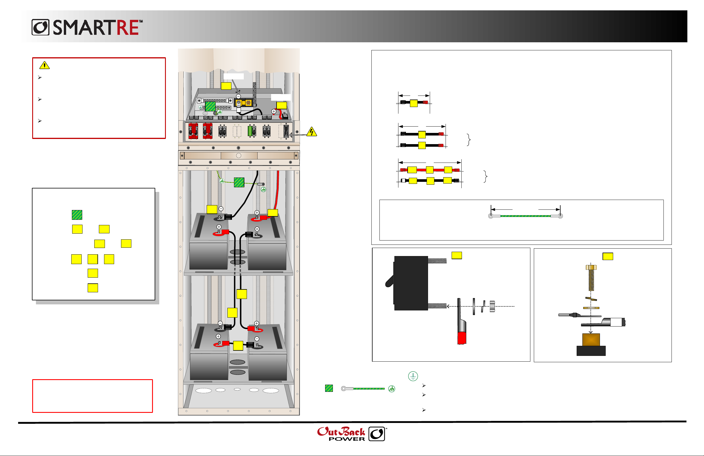
Battery Enclosure Cabling Kit – SRE-BC1
For a 48-volt Battery Bank
Electronics Enclosure
(Factory wiring not shown)
BAT (–)
5a
BAT (+)
6
4a
WARNING:
Shock Hazard
GROUND
CHARGE
SOLAR
INVERTER
AC
LOAD #1ACLOAD #2
BYPASS
INVERTER
GRID
GEN
AC OUT
AC IN
AC IN
DC
FAULT
CONTROL
LOAD
INVERTER
INPUT
CHARGER
Ensure the Inverter
Charger Breaker is in
OFF position BEFORE
making connections.
6
Intended for use as a universal connection kit for four 12-volt batteries,
wired in “series”, using one (1) SmartRE Battery Enclosure. Includes
the following cables:
20"
3/8" Lug 3/8" Lug
3/8" Lug
3/8" Lug
5/16" Lug
3/8" Lug
1
30"
2
3
40"
4a 4b
5a
4
4
5b
5
3/8" Lug
3/8" Lug
20” Black #1/0 AWG with 3/8" lugs on both ends. (x1)
30” Black #1/0 AWG with 3/8" lugs on both ends (x2)
3/8" Lug
3/8" Lug
40” Red #1/0 AWG with one 5/16” lug and one 3/8” lug (x1)
40” Black #1/0 AWG with 3/8" lugs on both ends (x1)
Connecting Cables:
Connecting Cables:
1. Connect .
2. Connect and .
3. Do NOT connect and yet.
4. Connect .
5. Then connect .
6. Then connect .
6
4a 5a
4b
1 2 3
4b
5b
5b
5b
12 Vdc
12 Vdc
NOTES:
4b
1. All cable lengths measure “eye-to-eye.
Eye-to-Eye
2. No hardware for securing the cable to the battery is provided with this kit. Hardware (nuts, bolts, and
washers) for securing the cable to the battery should comply with the specifications from the battery manufacturer.
12 Vdc
3
2
OFF
DC Breaker
1
Hardware Order on
4a
the DC Breaker:
Flat
Washer
BAT (+)
Locking
Washer
Nut
BAT (–)
from CC
SHUNT
Lock
Washer
Bolt
Hardware Order
5a
on the Shunt:
Flat Washer
BAT (–)
with 3/8" lug
with 5/16" lug
12 Vdc
IMPORTANT: All configurations must comply
with local and national electric codes. Consult
your local electric authority to ensure compliance.
Actual wiring requirements may vary. Factory
wiring is not shown.
900-0103-01-00 Rev A
© March 2010 OutBack Power Systems. All Rights Reserved.
Battery Enclosure
(Batteries shown wired in “Series”)
6
#6 AWG THHN recommended
IMPORTANT: Grounding
Battery Negative (–) to Chassis Ground Bond is done through the GFDI.
Proper cabinet grounding may still be required. Ground conductors are not provided with this kit.
Consult local electric code to ensure compliance.
This is intended for a Negative Ground installation. Do not use in a Positive Ground installation.
19009 62nd Avenue NE
Main Office
Arlington, WA USA
1.360.435.6030
 Loading...