

Page 1
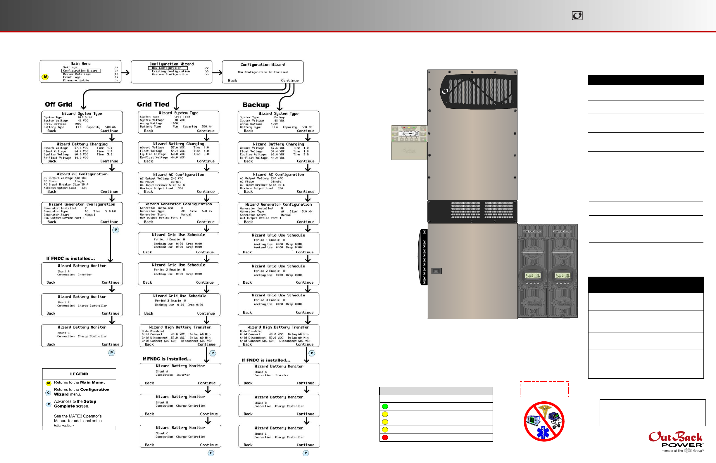
MAT E3 Programming
IM PORT AN T :
Programming should be done by a qualified installer who is trained on programming inverter power systems. Failure to program accurate parameters for the
system could potentially cause equipment damage. Damage caused by inaccurate programming is not covered by the limited warranty for the system.
Components
GS8 0 48 Inve rt e r/Cha rger
RADIAN Series
Ma jor Com pone nt s
Ra dian Syst em Produc t s
Not e : For automatic generator
start features see the MATE3
manual for details.
MATE3
Syste m
Displa y and
Controller
Com m unic ation
Ma na ge r
(H UB1 0)
FLEX m a x 8 0
Charg e C on t rolle rs
(x 2 ) ( Op t ional)
Inverter/Charger
GS Load Center
System Display
and Controller
Communications
Manager
FLEXnet DC Monitor (FNDC)
Surge Protector
Remote Temperature Sensor (RTS)
GS8048
GSLC175-PV-120/240
MATE3 (FW-MB3
mounting bracket)
HUB10
HUB 4
Opt iona l Out Ba c k Compone nt s
Charge Controller
*Including appropriate Mounting Bracket.
PV Combiner Box
FLEXmax 80*
FLEXmax 60*
PV8
PV12
900-0153- 01-00 Rev A.vsd\Page-1\ 2013-01-17
© 2012 OutBack Power Technologies. All Right s Reserved.
Co lo r
Green
Yellow
Yellow
Yellow
GS Loa d Ce nt e r
FN D C LED Ind ica t ors
Ba t t e ry Stat e-of -Ch arge
> 90% (blinks if charge parameters are met)
≥ 80%
≥ 70%
≥ 60%
Red
≥ 60% off, < 60% solid, < 50% blinks
(GSLC)
IM PORT ANT :
Not intended for use with
life support equipment.
Custome r-Supplie d Com pone nt s
AC Source
Main Electrical Panel
(or overcurrent device for
the AC source)
Electrical Distribution Subpanel
(Load Panel)
Battery Bank
Photovoltaic (PV) Array
(with PV Combiner Box [PV8 or PV12])
Contac t T e c hnic a l Support :
Telephone: +1.360.618.4363
Email: Support@outbackpower.com
Website: www.outbackpower.com
Utility Grid, or
AC Generator
Page 2

Mount ing
WARN I NG: Fire /Ex plosion H azard
Do not place combustible or flammable materials within 12 feet (3.7 m) of the equipment. This unit employs mechanical
relays and is not ignition-protected. Fumes or spills from flammable materials could be ignited by sparks.
WARN IN G: Pe rsonal I njury
Use safe lifting techniques and standard safety equipment when working with this equipment.
IM PORT AN T:
Clearance and access requirements may vary by location. Maintaining a 36” (91.4 cm) clear space in front of the system
for access is recommended. Consult local electric code to confirm clearance and access requirements for the specific
location.
Ra dia n Dim ensions (inc lude s M AT E3 a nd 2 FL EX m ax 8 0 Charge Cont rolle rs):
1
Wall Stud
Charge Controller
Mounting Bracket
29.1" (85 cm) tall X 35.4" (50 cm) wide
Ra dia n Mount ing:
1. Ensure the mounting surface is strong enough to handle 3 times the total weight of
1
all the components. Add a piece of plywood if necessary to strengthen the surface.
2
2. Attach the wall bracket to the surface centering the mounting holes on the sides
with the wall studs. Use all 6 mounting screws to secure the bracket.
3
3. Lift the inverter so that the inverter bracket is above the wall bracket.
4
4. Lower the Inverter into place so that the inverter bracket slips into the wall bracket.
5
5. Secure the inverter to the surface using a minimum
of 1 wall screw (or other appropriate hardware).
Wall Stud
Wall Board
Inverter
Bracket
Side View
900-0153- 01-00 Rev A.vsd\Page-2\ 2013-01-17
© 2012 OutBack Power Technologies. All Right s Reserved.
Plywood
(Optional)
3
4
Bracket
5
6
6. Follow the instructions for installing the GS Load Center.
7
7. Follow the instructions for installing the HUB Communication Manager.
8
8. Follow the instructions for installing the brackets for the charge controllers.
9
9. Follow the instructions for installing the bracket for the MATE3.
Wall
MATE3
Mounting
9
HUB
Manager
Bracket
7
MATE3
Communication
Radian Series
Inverter/Charger
6
GS Load Center
16 " (40.6 c m)
Plywood (Optional)
Wall Bracket
Wall Board
Charge Controller
Mounting Bracket
8
Wall Stud
2
FLEXmax 80
Charge Controllers
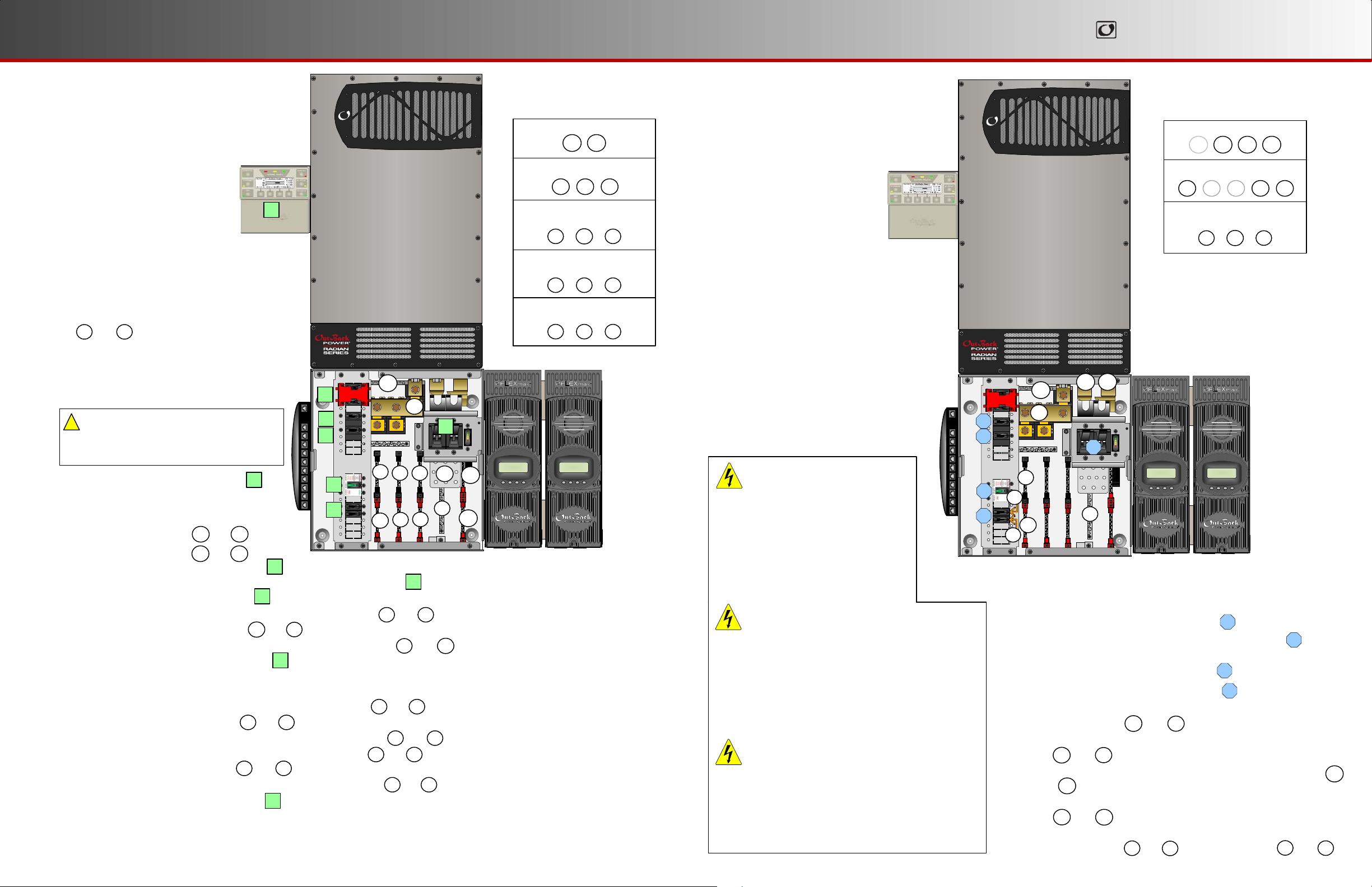
Wire Sizes/Torque
Re quire m e nts
GS80 4 8
MAT E 3
DC
Pla te
ON/OFF
INV
+ -
RELAY
Switch
12V
AUX
INV
AUX
10
1
N
N
L1 L2
L1 L2
E
E
GEN
OUT
U
U
3
5
6
Jum p e r
Battery
Remote
Temp
9
N
L1 L2
E
GRID
U
7
Fla t W ash er
Shu nt
2
20
22
18
1112131415
16
Cont r ol Wiring T e rm in a l Block:
The Inverter ON/OFF terminals are used for connecting an
external ON/OFF switch. To use this feature, the jumper
must be removed. (See Radian manual for details.)
The AUX terminals can be used to start a generator
or to control external devices.
AUX terminals are also available on the charge
controller and the FLEXnet DC. (See the charge
controller or FNDC installation manuals for details.)
9
9
HUB1 0
GSLC
10
Nega t i ve Ba t t e ry Ca ble
Connec t io ns
Ne gat ive (-)
22
2
4
19
17
Bol t 3 /8"
Loc k W ash er
21
21
1
AC Terminals - Inverter
2
DC Terminals - Inverter
AC Circuit Breakers
3
DC Circuit Breakers
4
GFDI
5
6
PV Circuit Breakers
Mechanical Interlock (Bypass)
7
PV Input/Output Terminals
8
Communication Ports
9
Auxiliary Terminals
10
AC OUT Bus Bar L1
11
AC OUT Bus Bar L2
12
13
GRID IN Bus Bar L1
14
GRID IN Bus Bar L2
15
GEN IN Bus Bar L1
16
GEN IN Bus Bar L2
17
AC Neutral
18
Ground
19
DC Positive (+) Plate
20
DC Negative (–) Bus Bar
21
PV Positive (+) Bus Bars
DC Negative (–) Plate (GS-SBUS)
22
8
Ch ar ge
Co nt ro ller # 2
9
10
8
Ch ar ge
Cont rol le r #1
9
10
Posit iv e Ba t t e ry Ca b le
Connec t io ns
Ba tte ry
Ne gat ive (–)
Lug
FN DC
DC Posit ive (+)
19
RADIAN Series
AC Wire Sizes a n d T orque V a lues
Wire Size Tor que
AWG In-lb
#14 - 10 20
#8 25
#6 - 4 35
#3 35
#2 40
#1 50
1/0 50
It is recommended that conductors be #6 AWG
THHN copper, or larger, rated to 75°C
(minimum) unless local code requires otherwise.
Min imum DC Ca b le b a se d on t he
DC Circ uit Bre aker
DC
Circ uit
Ca b le S ize
Bre a k e r
125 1/0 (70 mm2)
175 2/0 (70 mm2)
250 4/0 (120 mm2)
Torque Re qui reme nts
Circ uit Break e r St ud
M8 20 2.3
¼ - 20 35 4.0
5/16 - 18 50 5.6
3/8 - 16 225 25.4
DC P lat e s
3/8 - 16 225 25.4Upper holes (+) 60 6.8
3/8 - 16 225 25.4Lower holes (+) 225 25.4
Lower holes (+) 50 5.6
3/8 - 16 225 25.4Shunt Bolts (–) and GS-SBUS 60 6.8
CAUT I ON : E quipm e nt Dam a ge
!
When connecting cables from the inverter to the battery
terminals, ensure the proper polarity is observed.
Connecting the cables incorrectly can damage or
destroy the equipment and void the product warranty.
Fla t W as her
Pla te
Loc k W as her
mm
2.5 – 6
10
16 – 25
35
35
50
70
2
Tor que
In-l b Nm
35 4.060 #6 AWG (16 mm2)
35 4.080 #4 AWG (25 mm2)
50 5.6
225 25.4
225 25.4
Tor que
In-l b Nm
Bol t 3 /8"
Fla t W as her
Nu t
Nm
2.3
2.8
4.0
4.0
4.5
5.6
5.6
Ba tte ry
Pos itiv e (+ )
Lug
Page 3
Ene rgize/Start up
Proc e dures
De -e ne rgize/Shutdow n
RADIAN Series
Proc e dures
Pre -st a rt up Proc edures:
1. Double-check all wiring connections.
2. Inspect the enclosure to ensure no
tools or debris has been left inside.
3. Disconnect all AC loads at the
backup (or critical) load panel.
4. Disconnect the AC input feed to
the GSLC at the source.
4
To e ne rgize or sta rt t he Ou t Ba c k de vice s:
1. Using a digital voltmeter (DVM), verify 48 Vdc
on the DC input terminals by placing the DVM leads
on and .
1a 1 b
Confirm that the battery voltage is correct for the
inverter and charge controller models.
Confirm the polarity.
2a
5
1b
CAU T ION : Equipm ent Dam a g e
!
Incorrect polarity will damage
6
6
3
the equipment.
3a
2. Turn on (close) the GFDI circuit breaker.
1
1
4a4b5a
3. Verify that the PV output for each charge controller
is in the correct range of open-circuit voltage and
confirm the polarity by:
a) placing the DVM leads on and , and
b) placing the DVM leads on and .
2b2a
2c2 a
4. Turn on (close) the PV input circuit breakers.
2
2
3b
5. Turn on (close) the DC circuit breakers from the battery bank to the inverter.
6. If the inverter is in the Off state, turn it On.
7. Verify 120 Vac on the AC Output L1 TBB by placing the DVM leads on and .
8. Verify 120 Vac on the AC Output L2 TBB and .
9. Verify 240 Vac between the AC Output TBBs by placing the DVM leads on and .
10. Turn on (close) the AC output circuit breakers.
4
3a 3c
3b 3c
3a 3 b
5
11. Start the generator if appropriate. Verify 120/240 Vac on the terminals of the AC input sources.
12. Turn on the AC input feed to the GSLC at the source.
11. Verify 120 Vac on the GRID IN L1 TBB by placing the DVM leads on and .
12. Verify 120 Vac on the GRID IN L2 TBB and .
4b 3 c
13. Verify 240 Vac between the GRID IN TBBs by placing the DVM leads on and .
14. Verify 120 Vac on the GEN IN L1 TBB by placing the DVM leads on and .
15. Verify 120 Vac on the GEN IN L2 TBB and .
5b
3c
16. Verify 240 Vac between the GEN IN TBBs by placing the DVM leads on and .
17. Turn on (close) the AC input circuit breakers.
6
4a 3c
4a 4b
5a
5a 5b
18. Turn on the AC disconnects at the backup (or critical) load panel and test the loads.
900-0153- 01-00 Rev A.vsd\Page-3\ 2013-01-17
© 2012 OutBack Power Technologies. All Right s Reserved.
1a
3c
5b
3
3c
2c
2b
Func tiona l
Te st Points
Battery Voltage Test Points
1a 1b
PV Voltage Test Points
2a 2b 2c
AC OUT Voltage Test Points
(Terminal bus bar = TBB)
3a 3 b 3c
GRID IN Voltage Test Points
(Terminal bus bar = TBB)
4a 3c4b
GEN IN Voltage Test Points
(Terminal bus bar = TBB)
5a 3c5b
In 23.2 V 0.0 A
Out 27.6 V 0.0 A
0.000 kW 0.0 kWH
AUX: OFF Sleeping
In 23.2 V 0.0 A
Out 27.6 V 0.0 A
0.000 kW 0.0 kWH
AUX: OFF Sleeping
WARN I NG: Burn Ha za rd
Internal parts can become hot
during operation. Do not
remove the cover during
operation or touch any internal
parts. Be sure to allow them
sufficient time to cool down
before attempting to perform any
Test points 2d and 2e refer to the
right terminal of each circuit breaker.
maintenance.
WARN I NG: Le t ha l Volta ge
Review the system configuration to identify all
possible sources of energy. Ensure ALL
sources of power are disconnected before
performing any installation or maintenance on
this equipment. Confirm that the terminals are
de-energized using a validated voltmeter
(rated for a minimum 1000 Vac and 1000 Vdc)
to verify the de-energized condition.
WARN I NG: Le t ha l Volta ge
The numbered steps will remove power from
the inverter and charge controllers. However,
sources of energy may still be present inside
the GSLC and other locations. To ensure
absolute safety, disconnect ALL power
connections at the source.
Func tiona l
Te st Points
Battery Voltage Test Points
1a 1b 1c 1 d
PV Voltage Test Points
2b2a 2c 2 d 2 e
AC OUT Voltage Test Points
(Terminal bus bar = TBB)
3a 3 b 3c
1b
2a
2d
1c 1 d
2
3c
1d
2e
1b
3a
In 23.2 V 0.0 A
Out 27.6 V 0.0 A
0.000 kW 0.0 kWH
AUX: OFF Sleeping
3c
1c
In 23.2 V 0.0 A
Out 27.6 V 0.0 A
0.000 kW 0.0 kWH
AUX: OFF Sleeping
1
3
2
4
2a
3b
3c
2a
1
1
4
3
1b
3a
2e
3b
2d
To de -e ne rgize or shut dow n t he Out Ba c k de vice s:
1. Turn off (open) the AC circuit breakers.
2. Turn off (open) the DC circuit breakers for the battery.
Wait 5 minutes for the devices to internally discharge themselves.
3. Turn off (open) the PV circuit breakers.
4. Turn off (open) the GFDI circuit breaker.
5. Verify 0 Vdc on the first DC bus of the inverter by placing the
voltmeter leads on and .
6. Verify 0 Vdc on the second DC bus by placing the voltmeter leads
on and .
7. Verify 0 Vdc on one PV circuit by placing the voltmeter leads on
and .
8. Verify 0 Vdc on the other PV circuit by placing the voltmeter leads
on and .
9. Verify 0 Vac on the AC output circuit breakers by placing the
voltmeter leads on and . Repeat this step for and .
Page 4
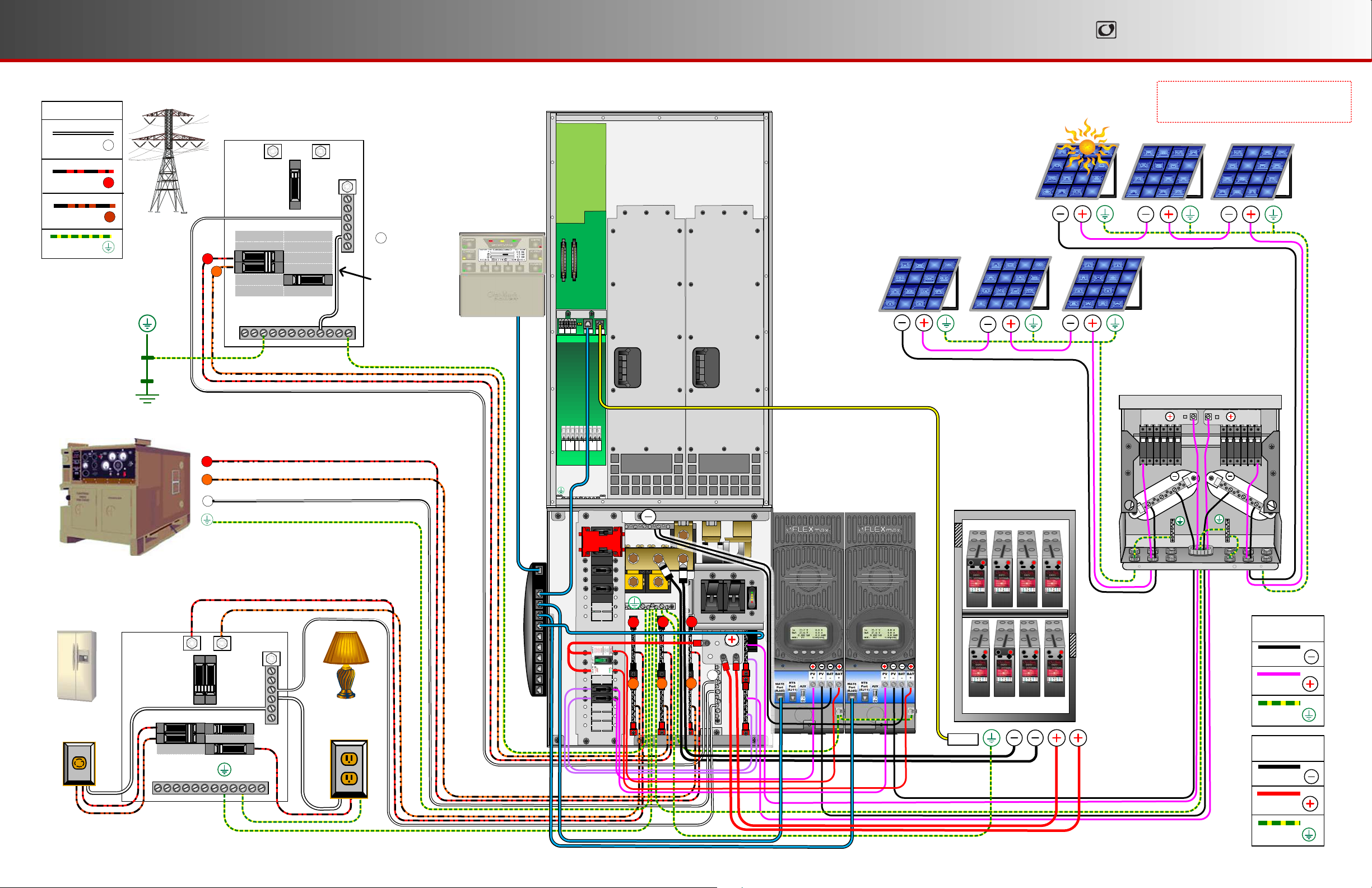
Ge neral Wiring
RADIAN Series
AC LEGEN D
Neutral
HOT L1
HOT L2
N
L1
L2
Ground
Ground
Ele c trode
Conduc t or
(Ground Rod)
AC
Dist ribut ion Pane l
L1
AC
Sou rce
L1
L2
GROUND
L2
NEU
N
Ne ut ra l-Gro und
Bon d
Radia n I nve rt er/Charge r
+ -
RELAY
Switch
Battery
12V
Remote
AUX
INV
Temp
AUX
PV Array # 1
IMPO RT A N T : Example only. Actual wiring
may vary depending on local electric code.
PV Array # 2
PV Arra y # 2
Factory wiring is not shown.
PV Ar ra y #1
AC Ge ne ra tor
Loads
(240 Vac)
AC
Subpa ne l
L1
GROUND
OIOIOIOIO
I
I
I
OIOIOIOIO
O
PV
LEGEN D
N
N
N
L1 L2
L1 L2
L1 L2
E
E
E
GRID
GEN
OUT
U
U
U
L1
L2
N
L1
L1
L1
L2
NEU
Charge
Cont r ol le r #1
Charge
Cont r ol le r #2
Bat t ery Ba nk
I
O
Negative
N
L2
L2
Loads
(120 Vac)
L2
Vented Battery Enclosure
RT S
Positive
Ground
BAT T ERY
LEGEN D
Negative
900-0153- 01-00 Rev A.vsd\ Page-4\2013- 01-17
© 2012 Out Back Power Technolo gies. All Rights Reserved.
Positive
Ground
 Loading...