

OutBack Power GS7048E, GS-IOB-230VAC Owner's Manual

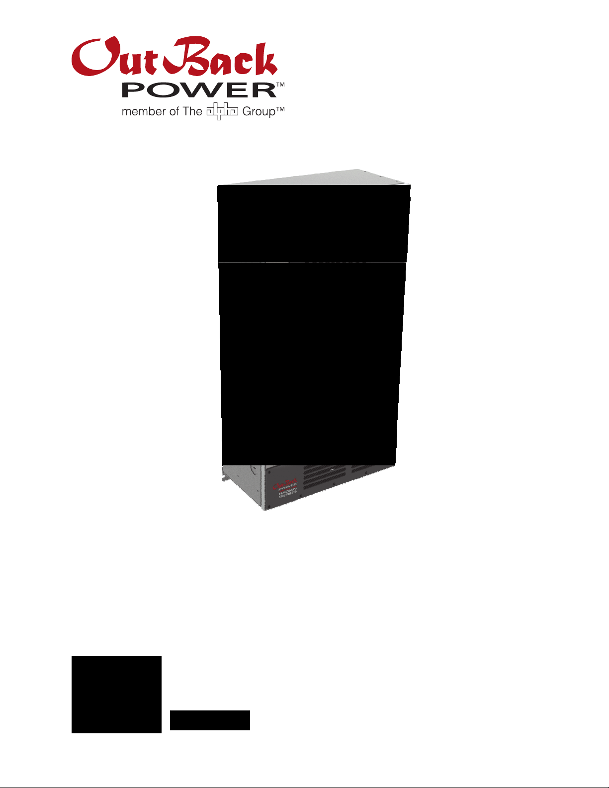
Radian™ Series
GS7048E & GS3548E Inverter/Chargers
Grid-Interactive and Stand-Alone Capability in the Same
Package
GridZero Technology Optimizes the Balance Between
Stored and Renewable Energy Sources, Minimizing Grid
Dependence
Advanced Battery Charging Prole (ABC) Supports
Leading-Edge Battery Technologies Including
Lithium-Ion
7000 and 3500 Watts of Continuous Power, Respectively
Field-Adjustable Input/Output Voltage and Frequency
Boundaries of 50/60Hz, 170-290VAC and 200-260V
Nominal, Respectively
Unsurpassed Surge Capacity
Dual AC Inputs
GS7048E
GS3548E
OutBack Power’s acclaimed Radian Series made the benets of
Grid/Hybrid technology available and accessible in one agile
powerful, platform ideal for nearly all o-grid or grid-connected
system architectures.
The Radian Series GS7048E and all-new GS3548E features dual AC
inputs for grid/generator exibility with no external switching required,
unparalleled surge capability and operational stability, easy eld
upgradeability and stacking capability for large system scaling, simplied
system commissioning through a powerful, easy-to-use conguration
wizard, and multi-mode operational exibility.
In addition, both models have new Advanced Battery Charging (ABC)
prole options to support leading-edge battery technologies such
as Lithium-Ion and others, and enhanced diagnostics for improved
performance. And both incorporate OutBack’s GridZero technology, a
superior level of intelligence in energy management for self-generation
and self-consumption programs, providing precise balancing between
using stored energy, solar and utility power, blending-in the latter to
overcome surges and load spikes when needed. GridZero operation
makes it possible for a smaller inverter and battery system to perform
like a much larger one when required, putting stored and renewable
energy sources to work and minimizing grid dependence.
Field Upgradeable Firmware
Field Serviceable Modular Design
Simplied Stacking Design
GS Load Center Option Allows for Quick and
Easy Installation
As truly global products, the Radian Series GS7048E and GS3548E
inverter/chargers oer selectable voltage and frequency for use in
a wide variety of locations, and innovative grid interface protection,
which allows precision programming and control to accommodate
shifting utility requirements in areas with high PV penetration or specic
interconnection requirements. Complete system interfacing using the
OutBack MATE3 and HUB communications manager enables the Radian
Series to be connected with other OutBack Power electronics providing
industry leading integration and a scalable power solution. Up to 10
units can be connected in parallel for systems up to 70kW continuous
power output.
The GS7048E and GS3548E are IEC certied to meet the most stringent
worldwide PV safety and emission standards.
This product is for Europe, Asia and other global markets.
OutBack reserves the right to make changes to the products and information contained in this document without notice.
Copyright © 2013-2014 OutBack Power. All Rights Reserved. OutBack is a registered trademark of The Alpha Group.
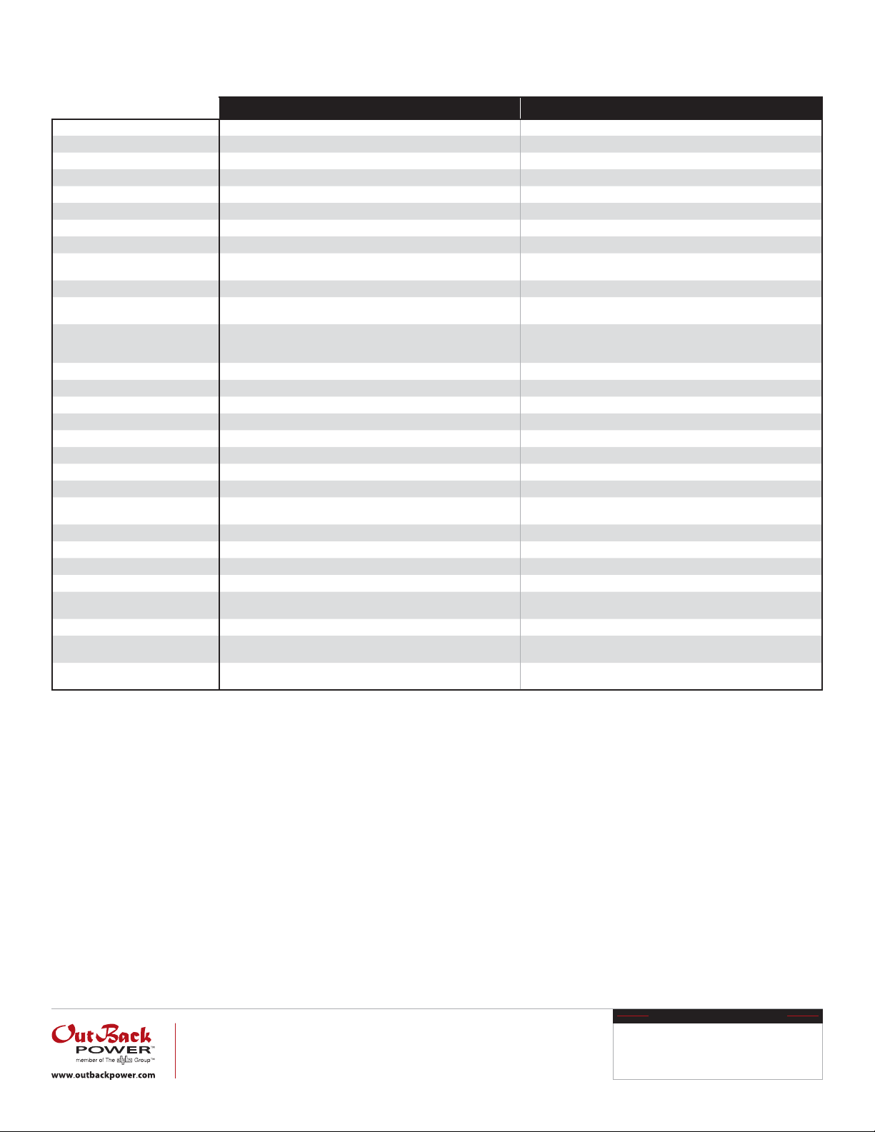
Radian Series International Specications 06/2014
Models
Nominal DC Input Voltage
Continuous Output Power (@ 25°C)
AC Output Voltage (Selectable)
AC Output Frequency (Selectable)
Continuous AC Output Current (@ 25°C)
Idle Consumption (Invert Mode, No Load)
Typical Eciency
CEC Weighted Eciency
Total Harmonic Distortion
Output Voltage Regulation
Maximum Output Current
Overload Capacity
AC Input Voltage Range (Adjustable)
AC Input Frequency Range (Default)
Grid-Interactive Voltage Range (Default)
Grid-Interactive Frequency Range
Maximum AC Input Current
Maximum Utility Interactive Current
Continuous Battery Charge Output
DC Input Voltage Range
Temperature Range
Accessory Ports
Non-Volatile Memory
Field Upgradable Firmware
Chassis Type
Certications
Warranty
Weight (lb/kg)
Dimensions H x W x D (in/cm)
GS7048E GS3548E
48VDC 48VDC
7000VA 3500VA
230VAC (210-250VAC) 230VAC (210-250VAC)
50Hz (60Hz) 50Hz (60Hz)
30AAC 15.2AAC
34W 34W
92% 92%
— —
Max. Total Harmonic: <5%
Max. Single Voltage Harmonic: <2%
±2% ±2%
1ms Peak: 100AAC
100ms RMS: 70.7AAC
100ms Surge: 16.3kVA
5 seconds: 11.5kVA
30 minutes: 7.9kVA
(L-N) 170 to 290VAC (L-N) 170 to 290VAC
45 to 55Hz @ 50Hz (54 to 66Hz @ 60Hz) 45 to 55Hz @ 50Hz (54 to 66Hz @ 60Hz)
(L-N) 208 to 252VAC (L-N) 208 to 252VAC
57.0 to 61.0Hz 57.0 to 61.0Hz
50AAC 50AAC
30A 15A
100.0ADC 50.0ADC
40 to 64VDC 40 to 64VDC
Rated: -20 to 50°C (power derated above 25°C)
Maximum:-40 to 60°C
Remote Temperature Sensor, MATE3 & HUB Communications Remote Temperature Sensor, MATE3 & HUB Communications
Yes Yes
Yes Yes
Vented Vented
IEC 62477-1, AS4777.2, AS477.3, EN61000-6-1, EN61000-6-3, EN61000-3-2, EN61000-3-3,
AS3100, CE, RoHS compliant per directive 2011/65/EU
Standard 5 year Standard 5 year
Unit: 125.0 / 56.7
Shipping: 140.0 / 63.5
Unit: 28 x 16 x 8.7 / 71 x 40.6 x 22.1
Shipping: 34.5 x 21 x 14.5 / 87.6 x 53.3 x 36.8
Max. Total Harmonic: <5%
Max. Single Voltage Harmonic: <2%
1ms Peak: 50AAC
100ms RMS: 35.35 AAC
100ms Surge: 8.2kVA
5 seconds: 5.8kVA
30 minutes: 4.0kVA
Rated: -20 to 50°C (power derated above 25°C)
Maximum:-40 to 60°C
IEC 62109-1, IEC 62477-1, AS4777.2, AS477.3, EN61000-6-1, EN61000-6-3, EN61000-3-2,
EN61000-3-3, AS3100, CE, RoHS compliant per directive 2011/65/EU
Unit: 81.0 / 36.7
Shipping: 93.0 / 42.1
Unit: 28 x 16 x 8.7 / 71 x 40.6 x 22.1
Shipping: 34.5 x 21 x 14.5 / 87.6 x 53.3 x 36.8
Worldwide Corporate Oces
North America
Tel: +1 360.435.6030
Fax: +1 360.435.6019
Latin America
Tel: +1 561.792.9651
Fax: +1 561.792.7157
Europe
Tel: +49 9122.79889.0
Fax: +49 9122.79889.21
AvAilAble From
Asia Pacic
Tel: +852 2736.8663
Fax: +852 2199.7988
Radian Series Inverter/Charger
GS7048E
Operator’s Manual

About OutBack Power Technologies
OutBack Power Technologies is a leader in advanced energy conversion technology. Outback products include true sine
wave inverter/chargers, maximum power point tracking charge controllers, and system communication components, as well
as circuit breakers, batteries, accessories, and assembled systems.
Grid/Hybrid™
As a leader in off-grid energy systems designed around energy storage, OutBack Power is an innovator in Grid/Hybrid system
technology, providing the best of both worlds: grid-tied system savings during normal or daylight operation, and off-grid
independence during peak energy times or in the event of a power outage or an emergency. Grid/Hybrid systems have the
intelligence, agility and interoperability to operate in multiple energy modes quickly, efficiently, and seamlessly, in order to
deliver clean, continuous and reliable power to residential and commercial users while maintaining grid stability.
Designed for FLEXgrid™ Operation
Selected OutBack Power products are designated as designed for FLEXgrid operation for their ability to support the design
and operation of a Grid/Hybrid system. FLEXgrid products perform or manage functions including system communication,
control, programming, charging, energy storage, and power conversion.
Only OutBack Power makes Grid/Hybrid systems and FLEXgrid products.
Contact Information
Address: Corporate Headquarters
5917 – 195th Street N.E.
Arlington, WA 98223 USA
Telephone: +1.360.435.6030
+1.360.618.4363 (Technical Support)
+1.360.435.6019 (Fax)
Email: Support@outbackpower.com
Website: http://www.outbackpower.com
European Office
Hansastrasse 8
D-91126
Schwabach, Germany
+49.9122.79889.0
+49.9122.79889.21 (Fax)
Disclaimer
UNLESS SPECIFICALLY AGREED TO IN WRITING, OUTBACK POWER TECHNOLOGIES:
(a) MAKES NO WARRANTY AS TO THE ACCURACY, SUFFICIENCY OR SUITABILITY OF ANY TECHNICAL OR OTHER
INFORMATION PROVIDED IN ITS MANUALS OR OTHER DOCUMENTATION.
(b) ASSUMES NO RESPONSIBILITY OR LIABILITY FOR LOSS OR DAMAGE, WHETHER DIRECT, INDIRECT, CONSEQUENTIAL OR
INCIDENTAL, WHICH MIGHT ARISE OUT OF THE USE OF SUCH INFORMATION. THE USE OF ANY SUCH INFORMATION WILL BE
ENTIRELY AT THE USER’S RISK.
OutBack Power Technologies cannot be responsible for system failure, damages, or injury resulting from improper
installation of their products.
Notice of Copyright
Radian Series Inverter/Charger Operator’s Manual © 2012 by OutBack Power Technologies. All Rights Reserved.
Trademarks
OutBack Power, the OutBack Power logo, FLEXpower ONE, Grid/Hybrid, and FLEXgrid are trademarks owned and used by
OutBack Power Technologies, Inc. The ALPHA logo and the phrase “member of the Alpha Group” are trademarks owned and
used by Alpha Technologies Inc. These trademarks may be registered in the United States and other countries.
Date and Revision
October 2012, Revision A (firmware revision 001.003 xxx)
Part Number
900-0145-01-00 Rev A

Table of Contents
Introduction.................................................................................................3
Audience .................................................................................................................................................................................3
Symbols Used ........................................................................................................................................................................3
General Safety .......................................................................................................................................................................3
Welcome to OutBack Power Technologies.................................................................................................................4
Functions ............................................................................................................................................................................................5
MATE3 ......................................................................................................................................................................................6
System Display and Controller ........................................................................................................................................6
Commissioning ............................................................................................7
Functional Test......................................................................................................................................................................7
Pre-startup Procedures ..................................................................................................................................................................7
Startup.................................................................................................................................................................................................7
Powering Down................................................................................................................................................................................ 8
Adding New Devices.......................................................................................................................................................................8
Firmware Updates ...........................................................................................................................................................................8
Operation ....................................................................................................9
Description of Input Modes..............................................................................................................................................9
Generator............................................................................................................................................................................................9
Support..............................................................................................................................................................................................10
Grid Tied............................................................................................................................................................................................11
UPS (Uninterruptible Power Supply).......................................................................................................................................13
Backup ...............................................................................................................................................................................................13
Mini Grid............................................................................................................................................................................................13
Description of Functions ................................................................................................................................................ 15
Inverting............................................................................................................................................................................................15
Search ................................................................................................................................................................................................16
Input...................................................................................................................................................................................................16
Generator..........................................................................................................................................................................................18
Transfer..............................................................................................................................................................................................18
Offset..................................................................................................................................................................................................19
Battery Charging ...........................................................................................................................................................................20
Charging Steps................................................................................................................................................................................20
Equalization .....................................................................................................................................................................................24
Battery Temperature Compensation.......................................................................................................................................25
Multiple-Inverter Installations (Stacking)...............................................................................................................................26
Power Save Levels..........................................................................................................................................................................28
Auxiliary Terminals ........................................................................................................................................................................29
System Display-Based Functions.................................................................................................................................32
Advanced Generator Start (AGS) ..............................................................................................................................................32
High Battery Transfer....................................................................................................................................................................32
Grid Use Time ..................................................................................................................................................................................32
Troubleshooting.........................................................................................33
Basic Troubleshooting.....................................................................................................................................................33
Module Select..................................................................................................................................................................................37
Error Messages ...................................................................................................................................................................39
900-0145-01-00 Rev A 1

Table of Contents
Warning Messages............................................................................................................................................................40
Disconnect Messages ...................................................................................................................................................... 42
Sell Status............................................................................................................................................................................. 43
Specifications .............................................................................................45
Electrical Specifications................................................................................................................................................... 45
Mechanical Specifications..............................................................................................................................................46
Environmental Specifications ....................................................................................................................................... 46
Regulatory Specifications...............................................................................................................................................46
Firmware Revision.............................................................................................................................................................47
Default Settings and Ranges......................................................................................................................................... 47
Definitions............................................................................................................................................................................ 49
Index .........................................................................................................51
List of Tables
Table 1 Troubleshooting ..............................................................................................................................33
Table 2 Error Troubleshooting...................................................................................................................39
Table 3 Warning Troubleshooting............................................................................................................40
Table 4 Disconnect Troubleshooting ......................................................................................................42
Table 5 Sell Status Messages ......................................................................................................................43
Table 6 Electrical Specifications for Model GS7048E.........................................................................45
Table 7 Mechanical Specifications for Model GS7048E....................................................................46
Table 8 Environmental Specifications for All Models........................................................................46
Table 9 AS4777.3 Acceptance Settings ..................................................................................................47
Table 10 GS7048E Inverter Settings ...........................................................................................................47
Table 11 Terms and Definitions ...................................................................................................................49
List of Figures
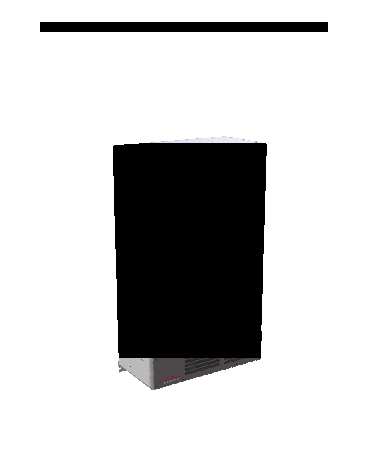
Figure 1 GS7048E Inverter/Charger............................................................................................................. 4
Figure 2 MATE3 System Display and Controller...................................................................................... 6
Figure 3 Charging Stages Over Time.........................................................................................................21
Figure 4 Charging Stages Over Time (Generator mode) ...................................................................21
Figure 5 Repeated Charging Cycles...........................................................................................................23
Figure 6 OutBack HUB4 and MATE3 ..........................................................................................................26
Figure 7 Example of Parallel Stacking Arrangement (Three Inverters) ........................................27
Figure 8 Example of Three-Phase Stacking Arrangement (Three Inverters)..............................27
Figure 9 AC Test Points...................................................................................................................................33
2 900-0145-01-00 Rev A
Introduction
Audience
This manual is intended for anyone required to operate the Radian Series Inverter/Charger. Operators
must be familiar with all the safety regulations pertaining to operating this kind of equipment as
required by local code. Operators must also have a complete understanding of this equipment’s
features and functions. Do not use this product unless it has been installed by a qualified installer in
accordance with the Radian Series Inverter/Charger Installation Manual.
Symbols Used
WARNING: Hazard to Human Life
This type of notation indicates that the hazard could be harmful to human life.
CAUTION: Hazard to Equipment
This type of notation indicates that the hazard may cause damage to the equipment.
IMPORTANT:
This type of notation indicates that the information provided is important to
the installation, operation and/or maintenance of the equipment. Failure to
follow the recommendations in such a notation could result in voiding the
equipment warranty.
General Safety
WARNING: Limitations on Use
This equipment is NOT intended for use with life support equipment or other medical
equipment or devices.
CAUTION: Equipment Damage
Only use components or accessories recommended or sold by OutBack Power
Technologies or its authorized agents.
900-0145-01-00 Rev A 3
Introduction
Welcome to OutBack Power Technologies
Thank you for purchasing the OutBack Radian Series Inverter/Charger. Designed for FLEXgrid™
operation, it offers a complete power conversion system between batteries and AC power. As part of
an OutBack Grid/Hybrid™ system, it provides grid-interactive service, selling excess renewable energy
back to the utility. It can also provide backup power or complete off-grid service if necessary.
Figure 1 GS7048E Inverter/Charger
4 900-0145-01-00 Rev A

Operation
Functions
Designed for FLEXgrid operation as part of an OutBack Grid/Hybrid system
Battery-to-AC inverting which delivers single-phase power (220 to 240 Vac at 50 or 60 Hz)
AC-to-battery charging from any AC source
Uses energy from photovoltaic arrays, wind turbines, and other renewable resources; use of
OutBack FLEXmax or FLEXmax Extreme charge controllers will optimize PV power production as
part of a Grid/Hybrid system.
Dual AC inputs allow direct connection to utility grid and AC generator
Rapid transfer between AC source and inverter output with minimal delay time
Six selectable input modes for different applications
Generator
Support
Grid Tied
UPS (Uninterruptible Power Supply)
Backup
Mini Grid
7000 watts (7 kW) continuous power at 48 Vdc
16.3 kVA peak surge capacity
Stackable in parallel configuration up to ten inverters
Stackable in three-phase configuration with three inverters
Modular internal design allows low idle consumption and high efficiency at both high and low
power operation
Field-upgradeable firmware
Certified by ETL to IEC 62477-1
Uses the MATE3 System Display and Controller (sold separately) for user interface as part of a
Grid/Hybrid system
IMPORTANT:
The Radian Series Inverter/Charger is not intended for use with the OutBack MATE or
MATE2 System Display and Controller. It is only compatible with the MATE3 System
Display and Controller.
: This product has a settable AC output range. In this book, many references to the output refer
NOTE
to the entire range. However, some references are made to 230 Vac or 50 Hz output. These are
intended as examples only.
900-0145-01-00 Rev A 5

Introduction
MATE3 System Display and Controller
The Radian inverter/charger has no external controls. It can operate normally without an external
control or interface. Basic modes and settings are pre-programmed at the factory. (See page 47 for
default settings.) The Radi
status or operating mode without a metering device.
The MATE3 System Display and Controller (sold separately) is an OutBack product designed to
accommodate programming and monitoring of a Grid/Hybrid power system. The MATE3 provides the
means to adjust the factory default settings to correctly match the installation where needed. It
provides the means to monitor system performance and troubleshoot fault or shutdown conditions.
It also has data logging and interface functions using the Internet.
Once settings are modified using a MATE3, the MATE3 can be removed from the installation. The
settings are stored in the nonvolatile memory of the Radian. However, it is highly recommended to
include a MATE3 as part of the system. This provides the means to monitor system performance and
respond quickly should it be necessary to correct a fault or shutdown condition.
The MATE3’s Configuration Wizard is capable of automatically configuring inverters to a series of
preset values. This is often more efficient than attempting to manually program each setting in each
inverter. Affected fields include system type, battery charging, and AC source configuration. (For
more information, see the MATE3 Owner’s Manual).
an inverter has no display or LED indicators. It is not possible to monitor its
NOTE:
002.010.xxx or higher.
The Radian Series Inverter/Charger can only be used with MATE3 firmware revision
IMPORTANT:
Some functions are not based in the inverter, but are part of the MATE3
system display’s firmware. They will not function if the system display is
removed. These functions are listed beginning on page 32. For a detailed
ption of
descri
Manual.
functions and programming, please see the MATE3 Owner’s
Figure 2 MATE3 System Display and Controller
6 900-0145-01-00 Rev A
Commissioning
Functional Test
WARNING: Shock Hazard and Equipment Damage
It is necessary to remove the inverter cover to perform these tests. The components are close together and
carry hazardous voltages. Use appropriate care to avoid the risk of electric shock or equipment damage.
Pre-startup Procedures
1. Ensure all DC and AC overcurrent devices are opened, disconnected, or turned off.
2. Double-check all wiring connections.
3. Inspect the work area to ensure tools or debris have not been left inside.
4. Using a digital voltmeter (DVM) or standard voltmeter, verify battery voltage. Confirm the
voltage is correct for the inverter model. Confirm the polarity.
5. Connect the MATE3 system display, if present.
CAUTION: Equipment Damage
Incorrect battery polarity will damage the inverter. Excessive battery voltage also may damage the inverter.
This damage is not covered by the warranty.
IMPORTANT:
Prior to programming (see step 5 below), verify the operating frequency of the utility or another AC source.
This is necessary for correct AC operation. The default setting is 50 Hz, but this can be changed to 60 Hz.
Startup
If steps are inapplicable, they can be omitted. However, it is highly recommended that all applicable
steps be performed in the following order.
If the results of any step do not match the description, see the Troubleshooting section on page 33.
To start the system:
1.
Close the main DC circuit breakers (or connect the fuses) from the battery bank to the inverter.
Repeat for every inverter present.
2. Confirm that the MATE3 is operational, if present. (See the MATE3 Owner’s Manual for a
description of the menu items that appear on a correctly functioning display.)
3. Turn on the inverter using the MATE3 or external switch. The Radian’s default condition is Off.
4. Using a DVM, verify 230 Vac (or appropriate voltage) between the “L” and “N” OUT terminals. Do
not turn on any AC circuit breakers at this time. (See page 33 for an illustration of AC test points.)
5. Using the MATE3, perfor
current, generator starting, and any oth
on page 9 and the Functions section beginning on page 15. Also refer to the MATE3 Owner’s
Manual and any other literature as needed.
m all programming for input modes, stacking, battery charging, AC
er functions. Refer to the Input Modes section beginning
900-0145-01-00 Rev A 7

Commissioning
After programming (if any) is completed, perform the following steps:
1. If other inverters are on the system, use a DVM to verify correct voltage from the “L” OUT terminal
on one inverter to the next. When stacked in parallel, the wires from one inverter to the next
should read 0 Vac (although individually they should still read full voltage with respect to neutral).
2. Close the AC output circuit breakers. If AC bypass switches are present, place them in the normal
(non-bypass) position. Do not connect an AC input source or close any AC input circuits.
3. Use a DVM to verify correct voltage at the AC load panel.
4. Connect a small AC load and test for proper functionality.
5. Close the AC input circuit breakers and connect an AC source. Using a DVM, check the appropriate
“L” and “N” input terminals for 230 Vac (or appropriate voltage). If a MATE3 system display is
present, confirm that the inverter accepts the AC source as appropriate for its programming.
Check the system display indicators for correct behavior.
6. The inverter may perform a full battery charge when first powered up. This can take several hours.
If restarted after a temporary shutdown, the inverter may skip most or all of the charging cycle. If
the battery charger has been enabled, confirm that it is charging by using the MATE3.
7. Test other functions which have been enabled, such as generator start, selling, or search mode.
8. Compare the DVM’s readings with the MATE3 meter readings. If necessary, the system display’s
readings can be calibrated to match the DVM more accurately. Settings that can be calibrated
include AC input voltage, AC output voltage, and battery voltage.
Powering Down
If steps are inapplicable, they can be omitted. However, it is highly recommended that all applicable
steps be performed in the following order. These steps will completely isolate the inverter.
To Power Down the System:
1. Turn off all load circuits and AC input sources.
2. Turn off all renewable energy circuits.
3. Turn each inverter OFF using the MATE3 system display or external switch.
4. Turn off the main DC overcurrent devices for each inverter.
Adding New Devices
When adding new devices to the system, first power down the system according to the preceding
instructions. After adding new devices, perform another functional test, including programming.
Firmware Updates
Updates to the Radian’s internal programming are periodically available. If multiple inverters are used
in a system, all units must be upgraded at the same time. See the MATE3 Owner’s Manual for details.
IMPORTANT:
All inverters will shut down during firmware updates. If it is necessary to run loads
while updating the firmware, bypass the inverter with a maintenance bypass switch
(if present). During this time, communication cables must remain connected and DC
power must remain on. Lack of network communication will cause the update to fail
and the inverter(s) may not work afterward. Inverters automatically update one at a
time. Updating each inverter requires about 5 minutes.
8 900-0145-01-00 Rev A

Operation
Description of Input Modes
The Radian inverter has two sets of input connections for multiple AC sources. (See the Radian Series
Inverter/Charger Installation Manual for more information.) With the MATE3, each input can be
programmed to a particular operating mode. Six modes are available, each with certain advantages
which make it ideal for a particular application. Some modes contain functions unique to that mode.
Both of the Radian’s inputs,
input can be set in the
Grid
can be set in the
NOTE:
because of inverter requirements. Each input can accept any AC source as long as it meets the
requirements of the Radian inverter and the selected input mode. If necessary, the
accept grid power. The opposite is also true.
When multiple inverters are stacked together (see page 26), the master inverter’s input mode is
impose
that was previously programmed. However, the slave will ignore its own input mode and use that of
the master. This also applies to any parameters in the mode menu (
so on).
The following pages compare the various features of each input mode.
The input terminals are labeled for grid and generator due to common conventions, not
d on all s
Gen AC Input Mode and Limits
lave inverters. The slave menu settings are not changed; they retain any input mode
and
Grid
Grid AC Input Mode and Limits
, can be programmed for separate modes. The mode for the
Gen
menu.
menu. The parameters for the
terminals can
Gen
Voltage Limit, Connect Delay
Gen
input
, and
Generator
The
Generator
waveform. In other modes, a “noisy” or irregular waveform may not be accepted by the inverter. This
mode allows these waveforms to be accepted. The charging algorithm of this mode is designed to
work well with any AC generator regardless of power quality or regulation mechanism. The generator
must still comply with the inverter’s nominal input specifications in the Input section of this manual.
(See page 16.)
mode allows the use of any generator, even one with a rough or imperfect AC
CHARGING
When the charger is enabled, the Radian will use the AC source t
page 20
then remain i
BENEFITS:
The Radian inverter will charge the batteries from the generator even when the generator is undersized, of
low quality, or has other problems. The recommended parameters for sizing a generator are listed on
page 18.
In cases where utility grid power
accept the power.
A programmable delay time is available which will allow a generator to stabilize before connection. In the
MATE3, this menu item is
Gen AC Input Mode and Limits
900-0145-01-00 Rev A 9
:
o charge the battery bank. (See
.) It will proceed through the battery charging cycle until it reaches the Float stage. It will
n the Float stage and maintain the batteries for as long as the AC source is present.
is unstable
Connect Delay
menu, depending on which input is being programmed.
or unreliable,
. It is available in either the
Generator
mode may allow the Radian inverter to
Grid AC Input Mode and Limits
or the

Operation
NOTES
:
The Offset function of the Radian inverter is unavailable in this mode. (See page 19 for more information.)
Any AC fluctuations that are accepted by t
exposed to these fluctuations. It may not be advisable to install sensitive loads under these conditions.
In this mode, the Radian uses “diode charging”. This function uses exact control of the charger, allowing it to
operate normally despite the quality of the input source. (Other modes may temporarily switch to diode
charging, but
Inverter soft key screen. (See the MATE3 Owner’s Manual for more information.)
While charging, the charger will not go silent (see page 22). After completing the charge, it will remain in the
Float charging stage unless this genera
otherwise removed.
Generator
uses it exclusively.) The MATE3 indicates diode charging by displaying
he inverter will be transferred to the output. The loads will be
in the
tor is stopped (either automatically or manually) or AC input power is
Support
The
Support
mode is intended for systems that use the utility grid or a generator. In some cases, the
amount of current available from the source is limited due to size, wiring, or other reasons. If large
loads need to be run, the Radian inverter augments (supports) the AC source, adding inverter and
battery power to ensure that the loads receive the power they demand.
In the MATE3 system display, the
input. The
Gen Input AC Limit
sets the maximum draw for the Gen input. This function takes effect if
Grid Input AC Limit
dictates the maximum AC draw for the Grid
the AC draw on the appropriate input exceeds its setting.
CHARGING
:
When the charger is enabled, the Radian will use the AC source to charge the battery bank. (See
page 20.) It will proceed through the entire battery charging cycle. After the end of the Float timer, it
will continue to alternate between Silent and Re-Float stages.
:
BENEFI
NOTES
TS
The large loads on the system can be powered while staying connected to the input, even if the input is
limited. Battery power prevents overload of the input source, while at the same time limiting the amount of
battery power used.
The inverter will offset the loads with excess renewable energy if it is available from the batteries. (See
page 19 for more information on the Offset function.)
A programma
MATE3, this menu item is
Gen AC Input Mode and Limits
ble delay time is availa
Connect Delay
ble which will allow an AC source to stabilize before connection. In the
. It is available in either the
menu, depending on which input is being programmed.
Grid AC Input Mode and Limits
or the
:
IMPORTANT:
If the AC loads exceed the amperage limit setting, the inverter will draw energy from the
batteries. If the loads are sustained, the batteries may discharge to the point of Low
Battery Cut-Out and the inverter may shut down with a Low Battery error. (See pages
Error! Bookmark not defined.
should be planned accordingly.
Because the inverter limits the current draw from the AC source, it will reduce the charge rate as necessary to
support the loads. If the loads equal the amperage setting, the charge rate will be zero.
If the AC loads
the batteries and use it to support the incoming AC current.
from
The
Support
10 900-0145-01-00 Rev A
exceed
function is not usable in any other input mode.
the amperage setting, the charger will begin operating in reverse. It will take power
and 39.) To prevent the loss of backup power, load use

Grid Tied
IMPORTANT:
Selling power to the utility company requires the authorization of the local
electric jurisdiction. The method used by the local utility company to
accommodate this will depend on their policies on this issue. Some may pay
for power sold; others may issue credit. Some policies may prohibit the use of
this mode altogether. Please check with the utility company and obtain their
permission before using this mode.
Operation
The
Grid Tied
mode allows the Radian inverter to become grid-interactive. This means that in addition
to using power from the utility grid for charging and loads, it can also convert excess battery power
and sell it to the utility grid. Excess battery power usually comes from renewable energy sources, such
as PV arrays, hydroelectric turbines, and wind turbines.
In this mode, the inverter will offset the loads with excess renewable energy if it is available from the
batteries. (See page 19 for more information on the Offset function.) If additional energy is
available
beyond what is consumed by the loads, the energy will be sold to the utility grid.
The grid-interactive function is integrally tied with the battery charger. (See page 20.) Where the
charger draws power from
the AC input and puts it into the batteries, the grid-interactive function
removes power from the batteries (or the DC system) and returns it to the AC input. When a
renewable source of energy raises the batteries above a designated reference point (or “target”), the
inverter exports power in order to bring the voltage back down or to prevent it from rising further.
The inverter uses several set points as targets for selling, particularly the battery charger settings. In the
MATE3, the
If the battery charger is not active, the target voltage used by the Radian inverter is
Grid-Tie Sell
See the MATE3 Owner’s Manual to change any of these settings.)
Unlike the other target voltages, the Radian inverter cannot import AC power to raise the batteries to the
Sell Voltage
The
Maximum Sell Current
the power sold. This item is available in the
Absorb Voltage, Float Voltage
menu. (See page
set point. It can only use excess DC power, if it is available, and export it as AC power.
Error! Bookmark not defined.
can be adjusted between 5 and 30 amps, in the event that it is necessary to limit
, and
Equalize Voltage
for mo
Grid Interface Protection
settings are all used as target voltages.
Sell Voltage
information on charging and selling.
re
menu .
in the
The
Grid Interface Protection
50 and 60 Hz. This changes the inverter’s input acceptance parameters, as well as its output.
CHARGING
:
menu also allows the inverter’s operating frequency to be changed between
When the charger is enabled, the Radian will use the AC source to charge the battery bank. (See
page 20.) It will proceed through the full battery charging cycle. After the end of the Float
continue to alternate between Silent an
BENEFITS
Excess power is returned to the utility grid.
NOTES
The inverter has a delay before selling will begin. This delay has a default setting of one minute, although it is
adjustable. Upon initial connection to the utility grid, the inverter may be required to perform a full battery
charge. This may delay the operation of the grid-interactive function.
The grid-interactive function only operates when excess DC (renewable) power is available.
The grid-interactive function is not available in any of the other input modes.
900-0145-01-00 Rev A 11
:
:
d Re-Float stages, entering the Selling stage as appropriate.
timer, it will

Operation
When power is returned to the utility grid, it may be possible to make the utility meter run backwards. The
net result would be to sell power to the utility company. However, this depends on whether there are other
loads in the system. Loads on the main panel (not on the inverter’s output) may consume this power as fast
as it is generated, preventing the meter from running backwards. In this case, the result of selling would be
to reduce the consumption of AC power, not reverse it.
The amount of power an inverter can sell is not equal to its specified output wattage. Its maximum selling
current is 30 Aac. The overall power will depend on the utility grid voltage. For example, if the voltage is
231 Vac, the inverter will sell 6.93 kVA. If the voltage is 242 Vac, the inverter will sell 7.26 kVA. Additionally,
output will vary with inverter temperature, battery type, and other conditions.
A good guideline is that the renewable source should be sized to continuously deliver no more than
85% of the inverter’s specified wattage (per inverter, in a multi-inverter system).
This recommendation is specifically for the inverter’s grid-interactive function. In some cases, the
source may be sized larger to account for environmental conditions or the presence of DC loads. This
depends on individual site requirements.
The grid-interactive function can only operate while the utility grid power is stable and within specific limits.
In Grid Tied mode, the inverter will operate in accordance with the Grid Interface Protection settings.
The default settings and ranges are listed in Table 10, which begins on page 47.
requ
ency vary outside the Grid Interface Protection limits, the inverter will
Frequency Trip
Over Frequency Trip (Hertz)
Over Frequency Clearance Time (seconds)
Under Frequency Trip (Hertz)
ce Time (seconds)
Under Frequency Clearance Time (seconds)
The
NOTE:
the inverter’s operating frequency, which must be set
correctly. See pages 7 and 49.
Frequency Trip
settings are dependent on
Mains Loss
Clearance Time (seconds)
Reconnect Delay (seconds)
If the inv
Due to va
If the AC voltage or f
disconnect from the utility grid to prevent selling under unacceptable conditions. These limits override
the AC source acceptance limits described on page 17, which are used in other input modes.
stops selling or disconnects due to Grid Interface Protection, the MATE3 will show the
erter
reason. Sell Status messages are listed on page 43. Disconnect messages are listed on page 42. Often
these m
essages will be the same.
rying requirements in different locations around the world, the grid-interactive settings are
adjustable. However, this is only available to operators with installer-level access. There are firm rules
concerning the acceptable voltage range, frequency range, clearance time during power loss, and
reconnect delay when exporting power back to the utility. Generally it is expected that the settings
cannot be altered by the end user. For this reason, it is necessary to change the installer password from
the default in order to get access to these settings. Once this password has been changed, the settings
can only be accessed by using the installer password. See pages 47 and 49 for more information.
erating in Grid Tied mode, contact the utility company that provides power to the installation.
fore op
Be
They can provide information regarding the rules that must be followed in order to export power back
to the utility. The items below are the selectable options for Grid Interface Protection. It may be
necessary to provide these options to the utility company to make certain their standards are met.
The utility may simply name a standard to be followed, as in AS 4777.3 for Australia. If this is the case, it
may be necessary to look up the requirements for this standard and program them accordingly.
STAGE 1 Voltage (basic settings)
Over Voltage Trip (AC Voltage)
Over Voltage Clearance Time (seconds)
Under Voltage Trip (AC Voltage)
Under Voltage Clearan
STAGE 2 Voltage (if required by utility)
Over Voltage Trip (AC Voltage)
Over Voltage Clearance Time (seconds)
Under Voltage Trip (AC Voltage)
Under Voltage Clearance Time (seconds)
See Table 10 for the default settings and ranges.
12 900-0145-01-00 Rev A

UPS (Uninterruptible Power Supply)
Operation
In
times. If the utility grid becomes unstable or is interrupted, the Radian can transfer to inverting in
minimal time. This allows the system to support sensitive AC loads without interruption.
CHARGING
When the charger is enabled, the Radian will use the AC source to charge the battery bank. (See
page 20.) It will proceed through the entire battery charging cycle. After the
timer, it will continue to alternate
BENEFITS
NOTES
mode, the Radian’s parameters have been optimized to reduce the response and transfer
UPS
:
end of the Absorption
between Silent and Re-Float stages.
:
Constant power is provided to the loads with virtually no drop in voltage or current.
The inverter will offset the loads with excess renewable energy if it is available from the batteries. (See
page 19 for more information on the Offset function.)
:
Due to the need for the Radian inverter to react quickly to AC source fluctuations, it must remain fully active
at all times. The inverter requires a continuous consumption of 42 watts.
Backup
The
Backup
This source will pass through the Radian inverter’s transfer circuit and will power the loads unless
utility power is lost. If utility grid power is lost, then the Radian inverter will supply energy to the loads
from the battery bank. When the utility power returns, it will be used to power the loads again.
mode is intended for systems that have utility grid available as the primary AC source.
:
:
between Silent and Re-Float stages.
mode.
UPS
end of the Absorption
e, unlike the
Support
mode. It does
CHARGING
When the charger is enabled, the Radian will use the AC source to charge the battery bank. (See
page 20.) It will proceed through the entire battery charging cycle. After the
timer, it will continue to alternate
BENEFITS
The inverter will offset the loads with excess renewable energy if it is available from the batteries. (See
page 19 for more information on the Offset function.)
This mode will continuously maintain the batteries in a fully-charged stat
not have the overhead consumption of the
Mini Grid
The Radian inverter can be programmed to automatically reject an AC source and run solely from
battery (and renewable) energy. In
(usually the utility grid) when the batteries run too low.
The Radian inverter runs on battery-supplied power for as long as the batteries can be sustained. It is
expected that the batteries will also be charged from renewable sources such as PV. When the
batteries become depleted, the system reconnects to the utility grid to operate the loads.
The inverter will reconnect to the utility grid if the battery voltage decreases to either the
Voltage
grid, if the charger is turned off, the Radian will use its transfer circuit to send grid power to t
If the charger is turned on, it will use the grid to charge the batter
set point (see page 22), or the Re-Bulk voltage (see page 23). Once it reconnects to the utility
Mini Grid
mode, the inverter only connects to the AC source
Re-Float
he loads.
y, as well as powering the loads.
900-0145-01-00 Rev A 13

Operation
While connected to the utility grid, any excess energy from the renewable source will be sent to the
loads and used to “offset” the use of grid power. When the renewable energy is equal to or greater
than the load demand, the utility grid will no longer be required. The Radian inverter will then
disconnect from the utility grid and begin running from batteries again. It will not disconnect until
these conditions are met.
CHARGING
:
The Radian inverter will wait for the batteries to pass through the charging stages until certain internal
charger settings are met (see below). This is true regardless of whether the Radian or the renewable
source is charging. This means that the regulator for the renewable source must be set to the same
settings as the Radian (or higher). See the MATE3 Owner’s Manual to locate the exact settings of the
Radian inverter.
If the reconnection was triggered by the
batteries to pass through the
Float Voltage
Re-Float Voltage
and
Float Time
will then enter Silent (see page 22) and continue repeating this part of the charging cycle u
onnects from the utility grid.
disc
set point, the inverter will only require the
settings (as well as Offset.) The inverter
ntil it
If the reconnection was triggered by the Re-Bulk voltage setting, the inverter will require the charger
to pass through the entire charge cycle, including the
and
Float Time
settings (as well as Offset). The inverter will continue repeating the Float part of the
Absorb Voltage, Absorb Time, Float Voltage
,
charging cycle until it disconnects from the utility grid.
See page 20 for more information on the battery charging cycle.
BENEFITS
Mini Grid
can be minimized or eliminated.
The inverter will offset the loads with excess renewable energy if it is available from the batteries. (See the
previous page and page 19 for more information on the Offset function.)
This mode is similar to to the high-battery transfer (HBX) mode used b
several differences (see below).
:
mode allows a system to take full advantage of renewable energy. Dependence on the utility grid
y the MATE3 sys
tem display, but it has
NOTES
14 900-0145-01-00 Rev A
:
This mode has similar priorities to the high-battery transfer (HBX) mode used by the MATE3 system display.
However, it is not compatible with HBX mode and cannot be used at the same time. When using
mode, HBX mode should be disabled to prevent conflicts.
When deciding whether to use
Mini Grid logic is based in the Radian inverter and can function in the absence of the MATE3. HBX logic
is based in the MATE3 and cannot function unless the MATE3 is installed and operating.
Mini Grid can use utility grid power to fully recharge the batteries on reconnection. HBX can only do so
under specific circumstances.
HBX set points have a wide range of settings. Mini Grid uses settings intended to protect the batteries
from excessive discharge; however, most of its settings are automatic and do not allow customization.
HBX works more efficiently when the renewable source is larger, but there is no specific requirement for
renewable size. Mini Grid is unable to work properly unless the renewable source is larger than the size
of the loads. (See previous page.) If this condition is not met, Mini Grid will not disconnect the inverter
from the utility grid.
HBX can be combined with the settings of any other Radian input mode (Generator, UPS, etc.). The
Mini Grid input mode is naturally limited to its own settings and does not have access to certain
functions of other modes. (See the first bullet above.)
See page 32 and the MATE3 Owner’s Manual for mo
Mini Grid
mode or HBX, the user should consider various advantages of each.
ormation on HBX.
re inf
Mini Grid
Operation
T
Description of Functions
The items in this section are states of operation common to all Radian inverters. These functions can
be used in most or all of the input modes described in the preceding section. Some can be manually
selected or enabled; others are automatic.
All items identified as settable or adjustable have set points which can be accessed using the remote
system display. (See the MATE3 Owner’s Manual for instructions on locating these set points.) The
default settings and ranges of adjustment are listed beginning on page 47 of this manual.
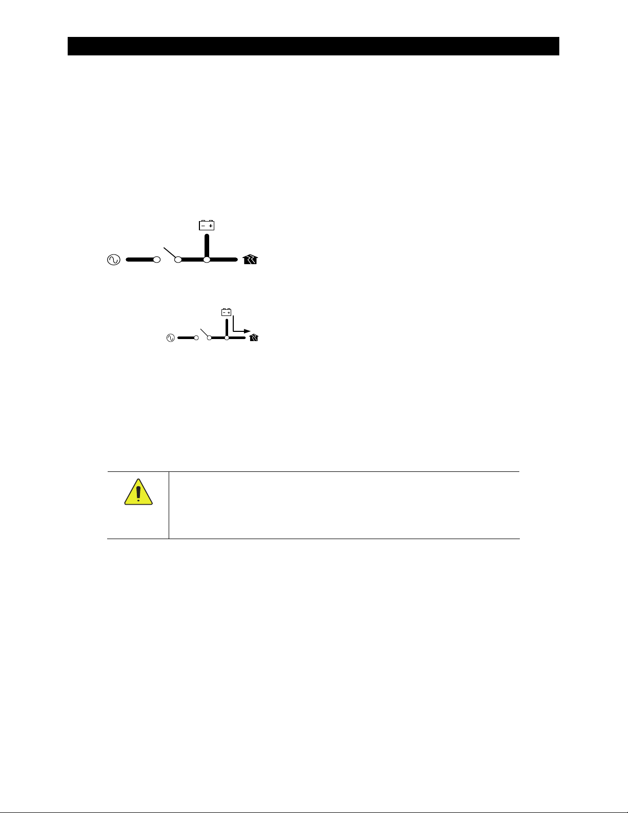
Each function is accompanied by a symbol representing the inve
DC
RANSFER
These items represent the input from the AC
source, the output to the AC loads, DC functions
rter and that function:
(inverting, charging, etc), and the transfer relay.
AC IN
The symbols
for each function may have other features depending on the function.
Inverting
Arrows on each symbol represent current flow.
The Radian inverter converts DC voltage from batteries into AC voltage that is usable by AC
appliances. It will continue to do this as long as the batteries have sufficient energy. The batteries can
be supplied or recharged from other sources, such as solar, wind, or hydroelectric power.
The inverter’s design uses two transformers and two high-frequency H-Bridge FET modules to achieve
the required high-wattage output. When not in use, the dual design allows half the inverter to shut
down for lower idle consumption.
The Radian inverter requires batteries to operate
. Other sources may not maintain DC voltages
that are consistent enough for the inverter to operate reliably.
CAUTION: Equipment Damage
Do not substitute other DC sources in place of the batteries. High or irregular voltages
may damage the inverter. It is normal to use other DC sources in conjunction with the
batteries and the inverter, but not in place of the batteries.
Certain functions will affect the inverter’s operation. These functions only operate when the inverter is
generating AC power on its own. They do not operate when the inverter is being supplied by an
AC source.
Low Battery Cut-Out
DC voltage drops below a specified level for 5 minutes, the inverter will stop functioning. The MATE3 will
give a
Low Battery V
Owner’s Manual. It is one of the error messages described on page 39. This function is intended to protect
both the batteries and the inverter’s output. (Continuing
distorted waveform.) This item is adjustable.
Low Battery Cut-In
point for 10 minutes, the low battery error will clear and the inverter will resume functioning. This item is
adjustable.
Connecting an AC source to charge the batteries will also clear a low battery error.
Output Voltage
to be used for different nominal (single-phase) voltages such as 220 Vac, 230 Vac, and 240 Vac.
900-0145-01-00 Rev A 15
: This function prevents the inverter from draining the batteries completely. When the
error. This appears as an event on the MATE3 system display, as described in the MATE3
to invert
: The recovery point from Low Battery Cut-Out. When the DC voltage rises above this
: The AC output voltage can be adjusted. Along with small changes, this allows the inverter
on a low DC voltage may produce a

Operation
: The inverter’s operating frequency (and AC input acceptance frequency) can be changed, but this
NOTE
requires high-level access. (See page 11 and Table 10, which begins on page 47.)
The invert
level, the inverter will immediately stop functioning and give a
event on the MATE3 system display, as described in the MATE3 Owner’s Manual. This is one of the error
messages displayed on page 39 of this manual. (If the voltage drops bel
automatically recovers.)
For the Radian inverter, the high battery cut-out voltage is 68 volts. It cannot be changed.
This function is intended to protect the inverter’s output and the loads. Continuing to invert on a high DC
voltage may produce a distorted waveform. Note that the inverter’s high battery cut-out does not alleviate
or solve the high battery condition itself; the cause is an external condition.
Search
er is also controlled by a high battery cut-out function. If the DC voltage rises above a certain
High Battery V
error. This appears as an
ow this point,
the inverter
An automated search circuit is available to minimize the power draw when no loads are present.
When enabled, the inverter does not always deliver full output. The output is reduced to brief pulses
with a delay between them. These pulses are sent down the output lines to see if a resistance is
present. Basically, the pulses “search” for a load. If a load is detected on the output, the inverter’s
output increases to full voltage so that it can power the load. When the load is turned off, the inverter
“goes to sleep” and begins searching again.
The sensitivity of Search mode is in increments of approximately 0.1 Aac. The default is 6 increments,
or about 0.6 Aac. A load which draws this amount or greater will “wake up” the inverter.
NOTE:
Due to load characteristics, these increments are only approximate and may not function
exactly as listed.
The pulse duration and the delay both have a time period that is measured in AC cycles. These two
items and the load detection threshold are adjustable.
Search mode may not be useful in larger systems with loads that require continuous power (e.g., clocks,
answering machines, fax machines). Search mode may cause nuisance shutdowns, or it may sleep so rarely
that there is no benefit.
Some devices may not be easily detected by Search mode.
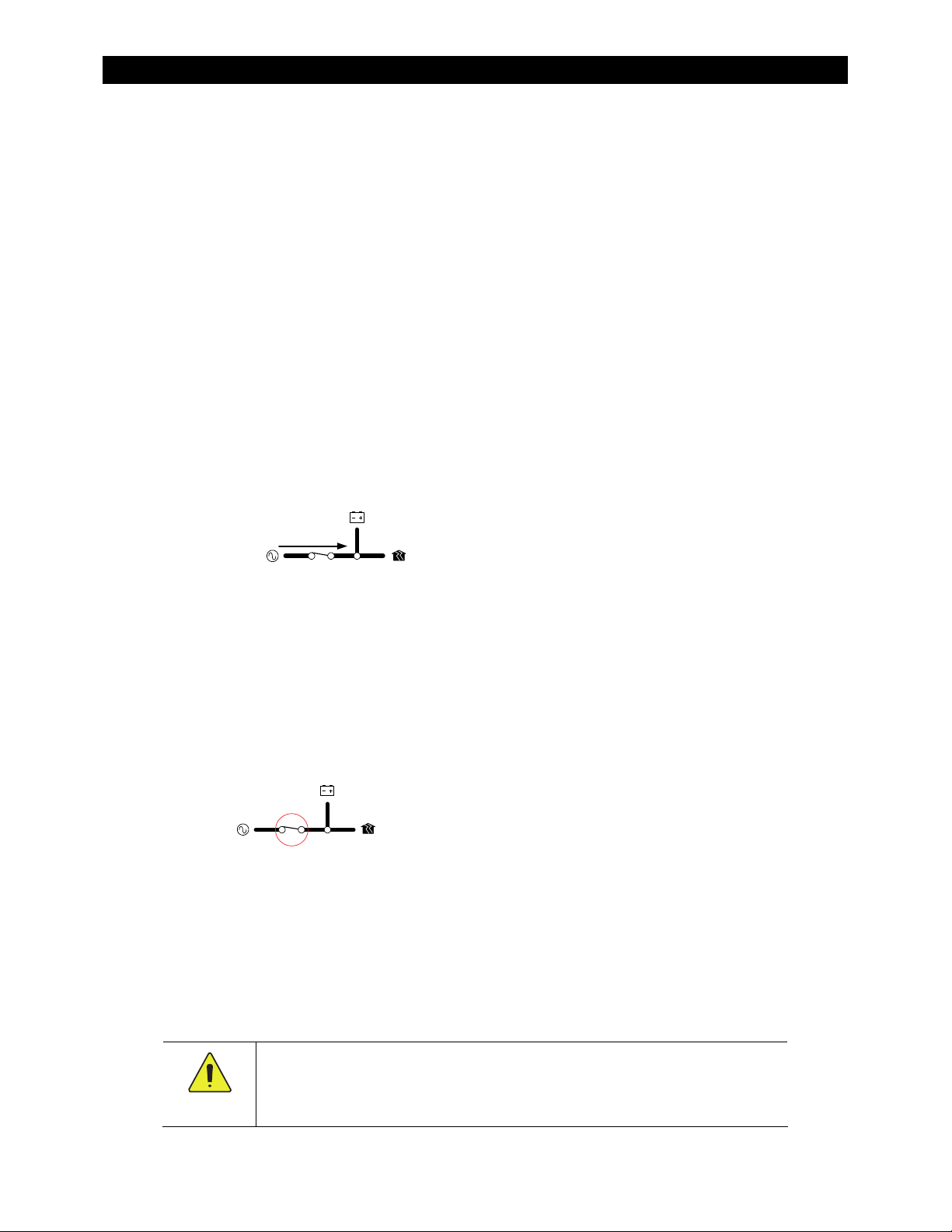
Input
When the Radian inverter input terminals are connected to a stable AC source, the inverter will
synchronize itself with that source and use it as the primary source of AC power. (See AC Source
Acceptance on page 17.) Its transfer relay will engage, linking the AC source directly with the
inverter’s output. It can also use the source
Charging on page 20.)
Two sets of AC input terminals are available. Both inputs are identical and can be used for any AC source.
However, for easy reference, the first input has been labeled
labeled
Each input has a separate set of input criteria and input modes. The programming for each input also has
identical content.
The independent inputs are intended to simplify the connection to multiple AC sources; however, only one
input can be used at a time. If both inputs are powered, the default setting is for the inverter to accept the
GRID
Priority
16 900-0145-01-00 Rev A
(for a generator). These designations are also used in the menus of the MATE3 system display.
GEN
input. This can be changed. In the MATE3 system display, these priorities are selected using
in the
AC Input and Current Limit
to charge batteries. (See Transfer on page 18 and Battery
(for the utility grid). The second input is
GRID
Input
menu.
Operation
Six input modes are available which affect the Radian inverter’s interactions with AC input sources. The
Grid Tied
battery power to assist a smaller AC source. See page 9 for descriptions of these and other input modes.
There ar
entitled Generator on page 18.)
The AC input current is used to powe
exceed the size of the AC overcurrent device or AC source. These devices should be sized appropriately
during planning. (See AC Current Settings on the next page. See the Radian Series Inverter/Charger
Installation Manual for more information.)
The loads powered by the inverter
entitled Transfer on page 18.)
mode allows the Radian to sell power using the input connection. The
e a number of considerations when selecting the type and size of an AC generator. (See the section
r both loads and battery charging. The combined amount should not
must not
CAUTION: Equipment Damage
Current draw in excess of the inverter’s transfer relay rating can damage the transfer
relay. This damage is not covered by warranty.
exceed the size of the inverter’s transfer relay. (See the section
Support
mode can use
AC Current Settings
The AC current settings control the amount of current that the inverter draws from the source(s). The
amount of current is controlled by the grid or generator limit settings. These settings should be
adjusted to match the size of the input circuit breaker. In the MATE3 system display, if the
Support
or
AC Input and Current Limit
, the inverter uses the generator settings.
Gen
input mode allows the Radian inverter to support the AC source with power from the batteries.
are installed with an AC source of limited amperage, the to
Input Priority
If the menus are set to
This is intended to protect a generator or source that may not be large enough to supply enough current for
both charging and loads. If the combined charging and loads exceed this setting, the inverter will reduce its
charge rate and give priority to the loads. If the loads exceed this number on their own, the charge rate will
be reduced to zero.
The
See page 10.
If multiple parallel inverters
amperage settings for all units must be less than the AC input circuit. The Configuration Wizard in the
MATE3 can perform this calculation. However, the inverters do not perform this calculation. If the MATE3 or
the Configuration Wizard are not used, it is necessary to divide the input size by the number of inverters and
assign an equal part of the amperage to each port.
menus are set to
, the inverter uses the grid settings.
Grid
tal combined
Inverter
AC Source Acceptance
The input source must meet the following specifications to be accepted. This is true in all modes
except
Voltage: 208 – 252 Vac (default; see Table 10 on page 47)
Frequency: If output frequency is set to 50 Hz, the input range of acceptance is 45 – 55 Hz. If the output
Grid Tied
frequency is set to 60 Hz, the input acceptance range is 55 – 65 Hz. (See Table 10.)
(see
NOTES
on page 18):
When these conditions are met, the inverter will close its transfer relay and accept the input source.
This occurs after a delay which is specified below. If the conditions are not met, the inverter will not
accept the source. If it was previously accepted and then rejected, the inverter will open the relay and
return to inverting power from the batteries. This occurs after a specified transfer delay, which is an
adjustable menu item.
The voltage limits can be adjusted to allow (or exclude) a source with weak or irregular voltages. These
items are adjustable in the appropriate menu of the MATE3 (
Input Mode and Limits
There can be side effects to changing the range of allowed voltages. See page 18.
). The settings are titled
Voltage Limit Lower
Grid AC Input Mode and Limits
and
Upper
.
or
Gen AC
900-0145-01-00 Rev A 17
Operation
Each of the AC inputs has a settable
input source to stabilize before connection.
The default setting for the Grid input is 0.2 minutes (12 seconds).
The default setting for the Gen input is 0.5 minutes (30 seconds).
These items are adjustable in the appropriate menu of the MATE3 (Grid AC Input Mode and Limits or Gen
AC Input Mode and Limits).
Connect Delay
NOTES:
The
Grid Tied
settings instead. (See page 11 for more information.) The inverter may not accept AC power if it meets the
settings noted her
Certain input modes
conditions are met. (See page 13.)
Several items external to the inverter may prev
conditions are met. One is the High Battery Transfer mode, which is operated by the MATE3 system display.
(See page 32 and the MATE3 Owner’s Manual.) Another is the MATE3’s
order all inverters to disconnect when set to
AC Acceptance is controlled separately between the Radian inverter’s two inputs. An AC source that is
unacceptable on one input may be acceptable on the other if the input mode or settings are different.
input mode does not use these acceptance limits and uses the
e but does not meet the
uch as
s
Mini Grid
Grid Interface Protection
may prevent the inverter from accepting AC power even if electrical
Drop
. This is intended as a warmup period which allows an
Grid Interface Protection
settings.
ent the inverter from accepting AC po
AC IN
PUT
. (See the MATE3 manual.)
wer even if electrical
hot key menu, which can
Generator
A generator should be sized to provide enough power for all inverters, both for loads and for battery
charging. The generator’s voltage and frequency must match the inverter’s acceptance settings.
It is usually recommended that the generator be sized at twice the wattage of the inverter system.
Many generators may not be able to maintain AC voltage or frequency for long periods of time if they
are loaded more than 80% of rated capacity.
The generator is required to have a stable output before its power is accepted by the inverter. Some
generators with less stable or uneven outputs may not be accepted. The use of the
Generator
mode may assist with this problem.
Transfer
The inverter uses a transfer relay to alternate between the states of inverting and of accepting an AC
source. Until the relay energizes, the output terminals are electrically isolated from the input that is in
use. When it closes, the input and output terminals become electrically common. (The terminals for
the unused input remain isolated during this time.) When the relay changes states, the physical
transfer delay is approximately 25 milliseconds (with the exception of the
input mode).
UPS
The relay contacts are limited to 50 amps per phase or leg. The continuous loads on that output
should never exceed this number. When connected to an AC source, the Radian inverter cannot limit
the load current. An overload condition is possible.
input
CAUTION: Equipment Damage
Current draw in excess of the inverter’s transfer relay rating can damage the transfer
relay. This damage is not covered by warranty.
18 900-0145-01-00 Rev A

Operation
The inverter does not filter or clean up the power from the AC source. The voltage and power quality
received by the output loads is the same as that of the source. If the voltage or quality do not meet
the inverter’s input requirements (see page 17), it will disconnect and return to the inverting mode.
NOTES
:
To ensure a smoother transition, it may be advisable to raise the inverter’s lower acceptance limit.
The default setting is 208 Vac. A higher setting will cause the inverter to transfer sooner in the event of a
quality problem.
If the AC source meets the inverter’s requirements but is irregular, any fluctuations will be transferred to the
loads. If the loads are sensitive, it may be necessary to improve the quality of the AC source.
The
Generator
than other modes. This should be considered before using this mode with sensitive loads. (See page 9.)
input mode is intended to accept irregular or unfiltered AC sources and is more likely to do so
In a stacked system, slaves are ordered to transfer at the same time as the master. If a slave does not
sense an AC source at the same time as the master, it will continue inverting, and will experience a
Phase Loss
error (see page 39). This appears as an Event on the MATE3 syste
m display, as described in
the MATE3 Owner’s Manual.
Offset
This function is designed to use excess battery energy to power the loads, even when an AC source is
present. This allows the system to take advantage of renewable energy sources, in effect “offsetting”
dependence on the AC source.
When a renewable source of energy raises the batteries above a designated reference point (or
“target”), the inverter exports power to the loads in order to bring the voltage back down or to
prevent it from rising further.
The inverter uses several set points as targets for the offset function, particularly the battery charger
settings. In the MATE3, the
Absorb Voltage, Float Voltage
, and
Equalize Voltage
settings are all used
as reference voltages. While the battery charger is operating, it will regulate the voltage at a level
appropriate for the target setting.
If none of the battery charger’s timers are active, the target voltage used by the Radian inverter is
Sell Voltage
in the
Grid-Tie Sell
import AC power to raise the batteries to the
menu. Unlike the other target voltages, the Radian inverter cannot
Sell Voltage
set point. It can only use excess DC power,
if it is available, and export it as AC power.
(See page
Error! Bookmark not defined.
charger. See the MATE3 Owner’s Manual to change any of these
NOTES
:
If the Radian inverter is in the
offset by the loads, the inverter will sell the remainder to the utility grid. Although the inverter can use the
Sell Voltage
unless the
If the inverter is in the
available than can be offset by the loads, it means the inverter is capable of running all of its loads using
renewable energy. The inverter will disconnect from the AC source as long as the excess renewable energy
is present.
setting as a target in most input modes (see below), it is unable to sell power to the utility grid
Grid Tied
mode is selected.
Support, UPS, Backup
Grid Tied
for more
information on how Offset relates to the battery
settings.)
input mode and more renewable energy is available than can be
, or
Mini Grid
input modes and more renewable energy is
900-0145-01-00 Rev A 19
 Loading...