

Page 1
FXR Series Inverter/Charger
FXR2012A FXR2524A FXR3048A
VFXR2812A VFXR3524A VFXR3648A
Installation Manual
Page 2

About OutBack Power Technologies
OutBack Power Technologies is a leader in advanced energy conversion technology. OutBack products
include true sine wave inverter/chargers, maximum power point tracking charge controllers, and system
communication components, as well as circuit breakers, batteries, accessories, and assembled systems.
Applicability
These instructions apply to OutBack inverter/charger models FXR2012A, FXR2524A, FXR3048A,
VFXR2812A, VFXR3524A, and VFXR3648A only.
Contact Information
Address: Corporate Headquarters
17825 – 59
Suite B
Arlington, WA 98223 USA
Website: http://www.outbackpower.com
th
Avenue N.E.
European Office
Hansastrasse 8
D-91126
Schwabach, Germany
Disclaimer
UNLESS SPECIFICALLY AGREED TO IN WRITING, OUTBACK POWER TECHNOLOGIES:
(a) MAKES NO WARRANTY AS TO THE ACCURACY, SUFFICIENCY OR SUITABILITY OF ANY
TECHNICAL OR OTHER INFORMATION PROVIDED IN ITS MANUALS OR OTHER DOCUMENTATION.
(b) ASSUMES NO RESPONSIBILITY OR LIABILITY FOR LOSS OR DAMAGE, WHETHER DIRECT,
INDIRECT, CONSEQUENTIAL OR INCIDENTAL, WHICH MIGHT ARISE OUT OF THE USE OF SUCH
INFORMATION. THE USE OF ANY SUCH INFORMATION WILL BE ENTIRELY AT THE USER’S RISK.
OutBack Power Technologies cannot be responsible for system failure, damages, or injury resulting from
improper installation of their products.
Information included in this manual is subject to change without notice.
Notice of Copyright
FXR Series Inverter/Charger Installation Manual © 2017 by OutBack Power Technologies.
All Rights Reserved.
Trademarks
OutBack Power, the OutBack Power logo, and Grid/Hybrid are trademarks owned and used by OutBack
Power Technologies, Inc. The ALPHA logo and the phrase “member of the Alpha Group” are trademarks
owned and used by Alpha Technologies Inc. These trademarks may be registered in the United States and
other countries.
Date and Revision
September 2017, Revision A
Part Number
900-0166-01-01 Rev A
Page 3

Table of Contents
Introduction ...................................................................................................... 5
Audience ......................................................................................................................................... 5
Symbols Used ................................................................................................................................. 5
General Safety ................................................................................................................................ 5
Welcome to OutBack Power Technologies ..................................................................................... 6
Models ............................................................................................................................................ 7
Inverter Model Names ................................................................................................................................ 7
Components and Accessories .................................................................................................................... 7
Planning ........................................................................................................... 9
Applications ..................................................................................................................................... 9
Input Modes .............................................................................................................................................. 10
Renewable Energy ........................................................................................................................ 11
Battery Bank ................................................................................................................................. 11
Generator ...................................................................................................................................... 14
Generator Sizing ....................................................................................................................................... 14
Three-Phase Source ..................................................................................................................... 14
Installation ...................................................................................................... 15
Location and Environmental Requirements .................................................................................. 15
Tools Required .............................................................................................................................. 15
Mounting ....................................................................................................................................... 15
Dimensions ................................................................................................................................... 16
Terminals and Ports ...................................................................................................................... 17
Wiring ............................................................................................................................................ 18
Grounding ................................................................................................................................................. 18
DC Wiring ...................................................................................................................................... 20
AC Wiring ...................................................................................................................................... 23
AC Sources .............................................................................................................................................. 24
ON and OFF Wiring ...................................................................................................................... 25
Accessory Wiring ...................................................................................................................................... 26
AUX Wiring ................................................................................................................................... 26
Generator Control ..................................................................................................................................... 28
AC Configurations ......................................................................................................................... 30
Single-Inverter .......................................................................................................................................... 30
Multiple-Inverter AC Installations (Stacking) ............................................................................................ 31
Stacking Configurations ........................................................................................................................... 33
Commissioning............................................................................................... 45
Functional Test ............................................................................................................................. 45
Pre-startup Procedures ............................................................................................................................ 45
Startup ...................................................................................................................................................... 45
Powering Down ........................................................................................................................................ 47
Adding New Devices ................................................................................................................................ 47
Operation ...................................................................................................................................... 47
Firmware Updates .................................................................................................................................... 48
.GIP File Installation for Grid Support ....................................................................................................... 48
Preventative Maintenance ............................................................................................................ 50
Definitions ..................................................................................................................................... 50
Index .............................................................................................................. 53
900-0166-01-01 Rev A 3
Page 4

Table of Contents
List of Tables
Table 1 Models ............................................................................................................................. 7
Table 2 Components and Accessories ........................................................................................ 7
Table 3 Battery Bank Elements .................................................................................................. 12
Table 4 Ground Conductor Size and Torque Requirements ...................................................... 18
Table 5 DC Conductor Size and Torque Requirements ............................................................. 20
Table 6 Terms and Definitions ................................................................................................... 50
List of Figures
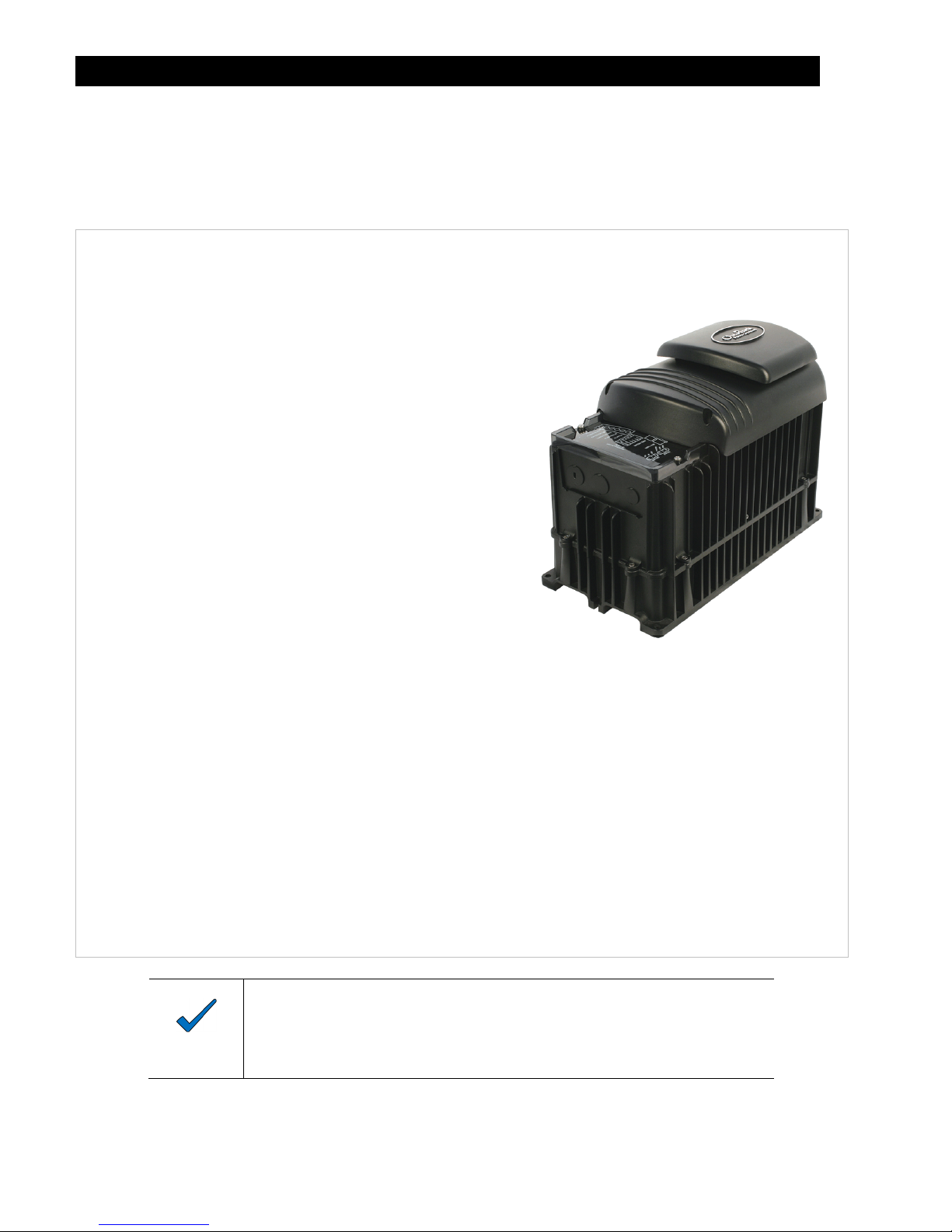
Figure 1 FXR Series Inverter/Charger ........................................................................................... 6
Figure 2 Components .................................................................................................................... 8
Figure 3 Applications (Example) ................................................................................................... 9
Figure 4 Dimensions ................................................................................................................... 16
Figure 5 Terminals, Ports, and Features ..................................................................................... 17
Figure 6 DC Ground Lug ............................................................................................................. 19
Figure 7 Chassis Ground/PE ....................................................................................................... 19
Figure 8 Required Order of Battery Cable Hardware .................................................................. 21
Figure 9 Battery Terminal Covers ............................................................................................... 21
Figure 10 DC Cover Attachment ................................................................................................... 22
Figure 11 Turbo Fan Wiring .......................................................................................................... 22
Figure 12 AC Terminals ................................................................................................................ 23
Figure 13 AC Sources ................................................................................................................... 24
Figure 14 AC Sources and Transfer Relay.................................................................................... 24
Figure 15 ON/OFF Jumper and Connections ................................................................................ 25
Figure 16 Accessory Connections ................................................................................................. 26
Figure 17 AUX Connections for Vent Fan (Example) .................................................................... 27
Figure 18 AUX Connections for Diversion (Example) ................................................................... 27
Figure 19 Two-Wire Generator Start (Example) ............................................................................ 28
Figure 20 Three-Wire Generator Start (Example) ......................................................................... 29
Figure 21 Single-Inverter Wiring .................................................................................................... 30
Figure 22 OutBack Communications Manager and System Display ............................................. 31
Figure 23 Example of Series Stacking Arrangement ..................................................................... 33
Figure 24 Series Wiring (Two Inverters) ........................................................................................ 34
Figure 25 Example of Parallel Stacking Arrangement (Three Inverters) ....................................... 35
Figure 26 Parallel Wiring (Four Inverters) ..................................................................................... 36
Figure 27 Example of Series/Parallel Stacking Arrangement (Four Inverters) .............................. 37
Figure 28 Series/Parallel Wiring .................................................................................................... 38
Figure 29 Example of Three-Phase Stacking Arrangement (Three Inverters) .............................. 39
Figure 30 Example of Three-Phase Stacking Arrangement (Nine Inverters) ................................ 39
Figure 31 Three-Phase Wiring (Three Inverters) ........................................................................... 41
Figure 32 Power Save Levels and Loads ...................................................................................... 42
Figure 33 Power Save Priority (Parallel) ....................................................................................... 44
Figure 34 Power Save Priority (Split-Phase) ................................................................................. 44
Figure 35 AC Terminals ................................................................................................................ 46
Figure 36 Grid Support Screens .................................................................................................... 49
4 900-0166-01-01 Rev A
Page 5
Introduction
Audience
This book provides instructions for the physical installation and wiring of this product.
These instructions are for use by qualified personnel who meet all local and governmental code
requirements for licensing and training for the installation of electrical power systems with AC and
DC voltage up to 600 volts. This product is only serviceable by qualified personnel.
Symbols Used
MORE INFORMATION
When this symbol appears next to text, it means that more information is available in other manuals relating to the
subject. The most common reference is to the FXR Series Inverter/Charger Operator’s Manual. Another common
reference is the system display manual.
WARNING: Hazard to Human Life
This type of notation indicates that the hazard could be harmful to human life.
CAUTION: Hazard to Equipment
This type of notation indicates that the hazard may cause damage to the equipment.
IMPORTANT:
This type of notation indicates that the information provided is important to the installation,
operation and/or maintenance of the equipment. Failure to follow the recommendations in
such a notation could result in voiding the equipment warranty.
NOTE:
This type of notation indicates useful information. This symbol is not always used.
General Safety
900-0166-01-01 Rev A
WARNING: Limitations on Use
This equipment is NOT intended for use with life support equipment or other medical
equipment or devices.
WARNING: Reduced Protection
If this product is used in a manner not specified by FXR product literature, the product’s
internal safety protection may be impaired.
CAUTION: Equipment Damage
Only use components or accessories recommended or sold by OutBack Power Technologies
or its authorized agents.
5
Page 6
Introduction
Welcome to OutBack Power Technologies
Thank you for purchasing the OutBack FXR Series Inverter/Charger. This product offers a
complete power conversion system between batteries and AC power. It can provide backup power,
sell power back to the utility grid, or provide complete stand-alone off-grid service.
12-, 24-, and 48-volt models
Output power from 2.0 kVA to 3.6 kVA
Designed to be integrated as part of an OutBack Grid/Hybrid™
system using FLEXware™ components
Battery-to-AC inverting with single-phase adjustable
output for such standards as 120 Vac, 100 Vac, or 127 Vac
(at 60 or 50 Hz)
AC-to-battery charging (FXR systems are battery-based)
Uses battery energy stored from renewable resources
~ Can utilize stored energy from PV arrays,
wind turbines, etc.
~ OutBack FLEXmax charge controllers will
optimize PV output
Inverter load support for a small AC source
Sell-back to utility (grid-interactive function)
~ Available in 24- and 48-volt models
Rapid transfer between AC source and inverter output
with minimal delay time
Uses the MATE3™ class of System Display and Controller products, or the AXS Port™ SunSpec
Modbus Interface (sold separately) for user interface as part of a Grid/Hybrid system
~ MATE3s system display is required for grid support functionality; requires revision 1.001.000
or greater
1
Supports the OPTICS RE™ online tool
for a cloud-based remote monitoring and control application
~ Requires MATE3-class device or AXS Port
~ Visit www.outbackpower.com to download
Uses the HUB10.3™ Communications Manager for stacking as part of a Grid/Hybrid system
~ Stackable in series, parallel, series/parallel, and three-phase configurations
nd
Listed by ETL to UL 1741 (2
Edition with supplement SA) and CSA 22.2
Figure 1 FXR Series Inverter/Charger
NOTE
This product has a settable AC output range. In this manual, many references to the output
refer to the entire range. However, some references are made to 120 Vac or 60 Hz. These
are intended as examples only.
:
1
Outback Power Technologies Intuitive Control System for Renewable Energy
6
900-0166-01-01 Rev A
Page 7
Introduction
Models
Vented FXR (VFXR) models have an internal fan and use outside air for cooling. On average,
VFXR models have higher power ratings than FXR models due to their greater cooling capabilities.
Sealed FXR models have an internal fan, but do not use outside air for cooling. To compensate,
sealed models are also equipped with the OutBack Turbo Fan assembly, using external air to
remove heat from the chassis. (Vented FXR models are not equipped with the Turbo Fan and
cannot use it.)
IMPORTANT:
All models, sealed or vented, must be installed indoors.
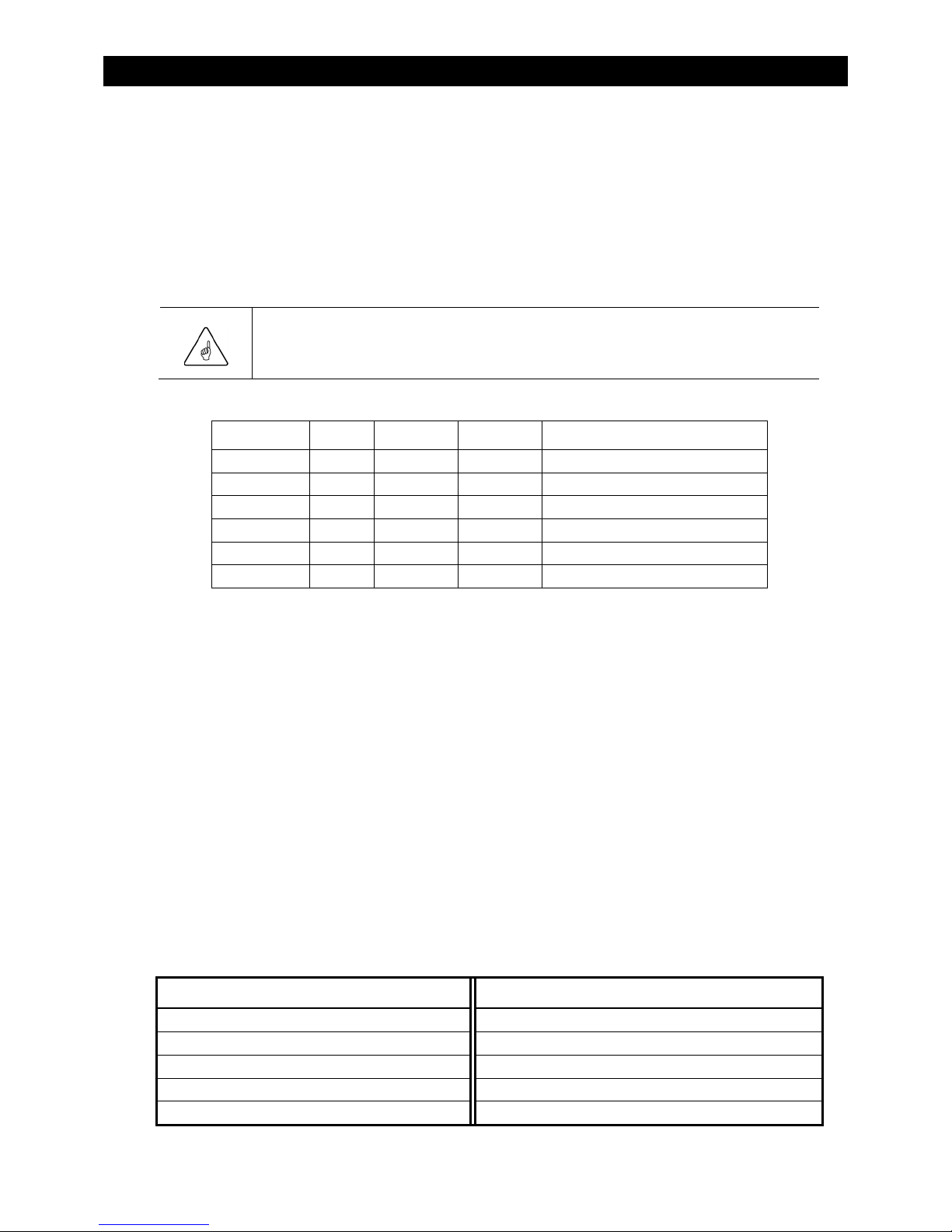
Table 1 Models
Model Type Power Battery Application
FXR2012A Sealed 2.0 kVA 12 Vdc Off-grid, backup
VFXR2812A Vented 2.8 kVA 12 Vdc Off-grid, backup
FXR2524A Sealed 2.5 kVA 24 Vdc Off-grid, backup, grid-interactive
VFXR3524A Vented 3.5 kVA 24 Vdc Off-grid, backup, grid-interactive
FXR3048A Sealed 3.0 kVA 48 Vdc Off-grid, backup, grid-interactive
VFXR3648A Vented 3.6 kVA 48 Vdc Off-grid, backup, grid-interactive
Inverter Model Names
FXR series model numbers use the following naming conventions.
The model number includes “FXR” as the inverter series. “R” indicates that the FXR was designed for
renewable applications. Off-grid and grid-interactive functions are integrated in the same inverter.
Vented models are preceded with “V”, as in “VFXR3648A”. If a model number does not begin with “V”, it
is a sealed model and is equipped with a Turbo Fan. This is not indicated otherwise.
The first two digits show the power of that model. For example, “FXR2012A” is 2000 watts.
The second pair of digits shows the inverter’s nominal DC voltage. For example, “FXR2524A” is 24 volts.
The model number is followed by “A”. This designates the inverter’s output as nominally 120 Vac (used
in North America, Latin America, Asia, and other regions).
Components and Accessories
Table 2 Components and Accessories
Components Included Accessories Included
Battery Terminal Cover, red FXR Series Inverter/Charger Quick Start Guide
Battery Terminal Cover, black “WARNING ELECTRICAL SHOCK” sticker
AC Plate Silicone Grease Packet
DC Cover (DCC) or Turbo Fan
Remote Temperature Sensor (RTS)
900-0166-01-01 Rev A
7
Page 8

Introduction
This plate is used for installations which do not utilize
OutBack’s optional FLEXware conduit boxes. The
knockouts are used to install strain relief for flexible cable.
NOTE: This plate is not to be connected to conduit.
DCC (DC Cover)
This covers the DC terminal area on vented inverters.
The DCC provides space to mount other components
such as a DC current shunt.
AC Plate
Turbo Fan Cover
Included in place of the DCC on sealed inverters. Convectively
cools chassis with the external OutBack Turbo Fan to allow
maximum power.
NOTE: Do not install the Turbo Fan on a vented inverter.
NOTE: The DC Cover or Turbo Fan does not replace the
battery terminal covers. These covers must be installed in
addition to the DCC or Turbo Fan.
Battery Terminal Cover
These protect the terminals from accidental contact. They
are made of stiff plastic with a snap-on design.
Always keep covers installed during normal operation.
8
Figure 2 Components
900-0166-01-01 Rev A
Page 9
r
Planning
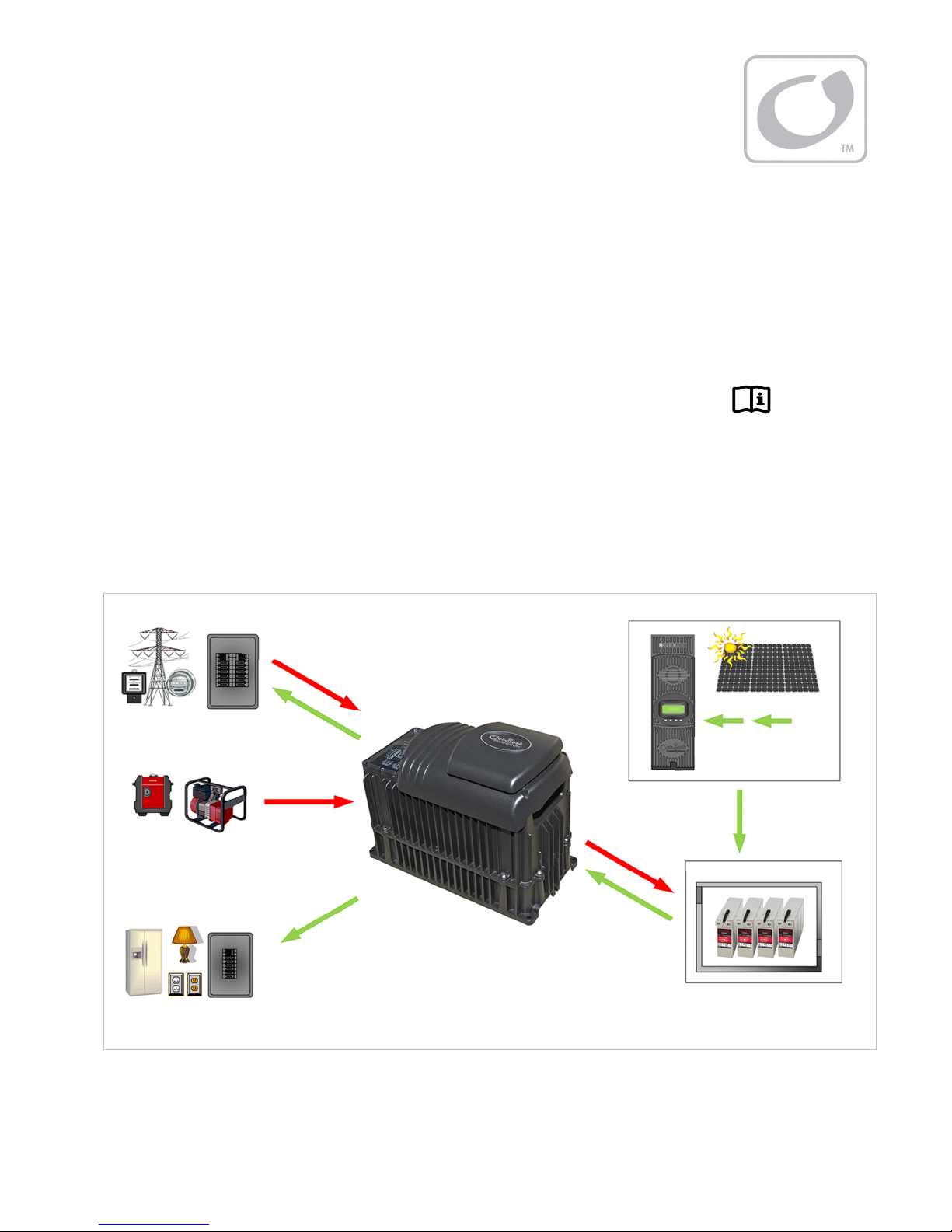
Applications
OutBack inverter/chargers are designed to use a battery bank to store energy. They work together
with power from the utility grid or from renewable energy sources, such as photovoltaic (PV)
modules, wind turbines, and other renewable sources. These sources charge the battery, which is
used by the inverter.
The FXR inverter’s settings can be changed to accommodate many applications.
These include off-grid, backup, and grid-interactive applications.
The FXR inverter has one set of terminals for a single AC source. However, it can use two different
AC sources when an external transfer switch is installed. The inverter can be independently
programmed for each source. It is common to use utility grid power and a gas or diesel generator.
Other combinations of AC sources are possible.
This product includes grid support functionality according to UL1741 SA. See the
Manual
for more information. Contact the utility company for any specific installation requirements.
Utility Grid
AC IN*
OR
AC Generator
AC OUT
AC IN*
Battery
Charging
AC or PV
Operator’s
PV Array
Charge
Controlle
DC IN
PV Harvest
Loads
AC OUT
*Two sources utilizing an AC selector switch on one input
In Figure 3, the inverter uses a bidirectional AC input to sell power back to the utility grid. The
power being delivered to the grid (labeled “AC Out”) is excess AC power not being used by the AC
loads. Selling requires an inverter/charger with
900-0166-01-01 Rev A
DC OUT
Load
Support
Figure 3 Applications (Example)
Grid Tied
mode available and active.
9
Page 10

Planning
Input Modes
The FXR inverter has many modes of operation. See the
Manual
for additional information on these modes, including reasons and considerations for using
FXR Series Inverter/Charger Operator’s
each mode.
The modes determine how the inverter interacts with an AC source. Each mode has functions and
priorities that are intended for a designated application. Each of the inverter’s input selections can
be set to a different operating mode to support different applications.
Generator
performance and waveform irregularities than other modes. The inverter can use generator power even
when the generator is substandard.
Support
of current available from the source is limited due to size, wiring, or other reasons. If large loads need to
be run, the FXR inverter augments (supports) the AC source. The inverter uses battery power and
additional sources to ensure that the loads receive the power they demand.
Grid Tied
charged and protected loads are serve, the inverter will export power to the utility grid. Grid support
functionality is available in this mode.
NOTE: This mode is only available in 24-volt and 48-volt models.
UPS
interruption when switching between AC input and batteries. The response speed has been increased so
that if an AC disconnect occurs the response time will be minimized.
: This mode enables the battery charging function to tolerate a wider range of generator
: This mode is intended for systems using utility grid or a generator. In some cases the amount
: This mode is intended for grid-interactive systems that are net metered. Once the battery is
: This mode is intended for systems primarily intended to maintain power to the loads with minimal
Backup
have specialty requirements such as selling or support. The AC source will flow through the inverter to
power the loads unless power is lost. If power is lost, then the inverter will supply energy to the loads
from the battery bank until the AC source returns.
Mini Grid
of renewable energy. It behaves like an off-grid system using the utility grid as a backup generator. The
system will use the renewable energy until the battery voltage falls to a specified low level. When this
occurs, the inverter will connect to the utility grid to power the loads. The inverter will disconnect from the
utility grid when the batteries are sufficiently recharged.
GridZero
of renewable energy. The loads will remain connected to the utility grid, but will restrict the grid use
except when no other power is available. The default power sources are the batteries and renewable
energy, which attempt to “zero” the use of the AC source. The batteries are discharged and recharged
(from renewable sources) while remaining grid-connected. This mode does not allow the inverter to
charge batteries or sell. Grid support functionality is available in this mode.
See the
: This mode is intended for systems that have the utility grid or a generator available, but do not
: This mode is intended for systems that have the utility grid as an input and a sizable amount
: This mode is intended for systems that have the utility grid as an input and a sizable amount
FXR Series Inverter/Charger Operator’s Manual
for additional information on these modes,
including the reasons and considerations for using each mode.
Programming
Selection of the input modes and all other inverter programming is performed using a system
display such as the MATE3s. This product can customize a wide range of parameters.
10 900-0166-01-01 Rev A
Page 11
Renewable Energy
The FXR inverter cannot connect directly to PV, wind turbines, or other unregulated DC sources.
The batteries are the inverter’s primary source of power.
A renewable energy source is always treated as a battery charger, even if all of its power is used
immediately by the inverter. The renewable source must have a charge controller, or some other
regulation method, to prevent overcharging. OutBack Power’s FLEXmax family of charge
controllers can be used for this purpose, as can other products.
Planning
Battery Bank
When planning a battery bank, consider the following:
Cables
length will determine the placement of the battery bank. Local codes or regulations may apply and may
take priority over OutBack recommendations.
Battery Type
The default inverter/charger settings assume a deep-cycle stationary lead-acid battery, such as
OutBack’s EnergyCell RE or NC series batteries. The charging configuration is highly customizable
so that lithium-ion and other advanced chemistry charging cycles can be accommodated. Consult
the documentation for the specific batteries used in the system to ensure that the settings are
appropriate.
Nominal Voltage
different depending on inverter model. Before constructing a battery bank, check the inverter model and
confirm nominal battery voltage.
Charger Settings and Maintenance
and is usually recommended for safety reasons. It may be necessary to use a fan to ventilate the
battery enclosure.
Batteries must be regularly maintained according to the instructions of the battery manufacturer.
: Recommendations for battery cable size and length are shown on page 20. The maximum
: The FXR inverter/charger uses a three-stage charge cycle.
: These inverters are designed to work with specific battery bank voltages, which are
: A vented battery enclosure may be required by electric code
IMPORTANT:
Battery charger settings need to be correct for a given battery type. Always follow battery
manufacturer recommendations. Making incorrect settings, or leaving them at factory
default settings, may cause the batteries to be undercharged or overcharged.
CAUTION: Hazard to Equipment
Batteries can emit vapors which are flammable and which are corrosive over long periods
of time. Installing the inverter in the battery compartment may cause corrosion which is
not covered by the product warranty. (Sealed batteries may be an exception.)
900-0166-01-01 Rev A
11
Page 12

Planning
Bank Size:
Battery bank capacity is measured in amp-hours. Determine the required bank
specifications as accurately as possible, beginning with the items below. This avoids underperformance
or wasted capacity.
These ten items are obtainable in different places, summarized in Table 3. Some of the information is
specific to the site or application. Some can be obtained from the battery manufacturer. Information on
OutBack products is available from OutBack Power Technologies or its dealers.
A. Size of load:
B. Daily hours of use:
These are the most basic
and essential factors used
to determine bank size.
C. Days of autonomy:
D. Application: This often helps define or prioritize the previous three items. Off-grid systems often
require enough capacity to last for an extended period before recharging. Grid-connected systems
frequently need only enough capacity for short-term backup during outages.
E. Conductor efficiency: Wire size and other factors
will waste power due to resistance and voltage drop.
Typical acceptable efficiency is 96 to 99%.
F. Inverter efficiency: FXR specifications list “Typical
Any losses are essentially amp-hour
capacity that the system cannot use.
The battery bank size can be
increased to account for losses.
Efficiency” to help estimate operating loss.
G. System DC voltage: Each inverter model
requires a specific DC voltage to operate.
H. Battery voltage: Most individual battery
voltages are less than the system DC voltage.
The batteries may need to be placed in series
to deliver the correct voltage.
I. Capacity: Battery capacity, which is measured
in ampere-hours (amp-hours or Ah), is not
usually a fixed number. It is specified based
on the rate of discharge. For example, the
OutBack EnergyCell 200RE is rated at 128.4
Ah when discharged at the 4-hour rate (to
terminal voltage 1.85 Vpc). This is a high rate
of discharge that would hypothetically drain the
battery in 4 hours. The same battery is rated
at 170 Ah when used at the 20-hour rate.
In general, use the 8-hour capacity or less.
The larger the load, the more severe the
discharge. In these cases conservative values
with faster discharge times from the table (for
Battery Bank Elements
Item Source of information
. Load Size
A
. Daily Hours
B
. Days of Autonomy
C
. Application
D
. Conductor Efficiency
E
. Inverter Efficiency
F
. System Vdc
G
. Battery Vdc
H
Capacity Ah
I.
Example:
Model
200RE 82.0 120.0 119.1 128.4 148.8 170.0
220GH 127.3 151.4 162.9 169.6 190.8 206.0
. Maximum DoD
J
Table 3
Site-specific
Site-specific
Site-specific
Site-specific
Site-specific
Inverter manufacturer
Inverter manufacturer
Battery manufacturer
Battery manufacturer
Discharge in Hours
1 2 3 4 8 20
Battery manufacturer
example, the 2- or 3-hour capacity) are better.
To choose accurately, the best method is to divide each Ah figure by the discharge in hours. (An
example from Table 3 for the OutBack 200RE would be 119.1 ÷ 3 hours = 39.7 Adc.) If the number is
equal or greater than the load size (in DC amperes), that column can be used as the capacity.
NOTES:
~ The battery’s selected rated capacity may have little to do with the actual hours of use; this figure
simply reflects the rate of discharge.
~ Use battery specifications for terminal voltage 1.85 Vpc whenever possible.
~ Capacity ratings are for batteries at 25°C. Capacity is reduced at cooler temperatures.
J. Maximum depth of discharge (DoD): Most batteries cannot be discharged below a certain level
without damage. The bank requires enough total capacity to keep this from happening. DoD is
usually described as a percentage, although it is shown as a decimal in calculations.
12 900-0166-01-01 Rev A
Page 13

Planning
To Calculate Minimum Battery Bank Size (refer to previous page for letter designations):
1. The load size, item A, is measured in watts. Compensate this figure for efficiency loss. Multiply the
conductor efficiency by the inverter efficiency (E x F). (These items are represented as percentages, but
may be displayed as decimals for calculation.) Divide item A by the result.
2. Convert the compensated load into amperes (Adc). Divide the step 1 result by the system voltage (G).
3. Determine the best battery capacity (I) by dividing each rated capacity by the time in hours (as shown in
Table 3). This is the estimated discharge rate at that battery capacity. The number is usable if the step 2
result (the actual load rate) does not exceed it. Choose the closest (or smaller) rated amp-hour capacity.
4. Determine the daily load consumption in ampere-hours (Ah). Multiply the step 2 result by the daily usage
hours (item B).
5. Adjust the total for required days of autonomy (the days the system must operate without recharging) and
the maximum DoD. Multiply the step 4 result by C and divide by J.
The result is the total amp-hour capacity required for the battery bank.
6. Determine the number of parallel battery strings required. Divide the Ah figure from step 5 by the
individual battery capacity (I) determined in step 3. Round the result to the next highest whole number.
7. Determine the total number of batteries required. Divide the system voltage by the battery voltage
(G ÷ H). Multiply the result by the step 6 result.
The result is the total required quantity of the chosen battery model.
EXAMPLE #1
. Backup loads: 1.0 kW (1000 W)
A
. Hours of use: 8
B
. Days of autonomy: 1
C
. Grid-interactive system
D
(FXR3048A inverter)
. Conductor efficiency: 98% (0.98)
E
. Inverter efficiency: 93% (0.93)
F
. System voltage: 48 Vdc
G
. Batteries: OutBack EnergyCell
H
220GH (12 Vdc)
. Capacity determined at 8-hour rate: 184.8 Ahr
I
. Maximum DoD: 80% (0.8)
J
EXAMPLE #2
. Backup loads: 720 W
A
. Hours of use: 2.5
B
. Days of autonomy: 2
C
. Off-grid system (VFXR3524A inverter)
D
. Conductor efficiency: 97% (0.97)
E
. Inverter efficiency: 92% (0.9)
F
. System voltage: 24 Vdc
G
. Batteries: OutBack EnergyCell
H
200RE (12 Vdc)
. Capacity determined at 3-hour rate: 119.1 Ahr
I
. Maximum DoD: 50% (0.5)
J
900-0166-01-01 Rev A 13
1. A ÷ [E × F] 1000 ÷ (0.98 × 0.93) = 1097.2 W
2. 1 ÷ G 1097.2 ÷ 48 = 22.9 Adc
3. I = Ah ÷ hours 184.8 ÷ 8 = 23.1 Adc (larger than 22.9;
Compare to 2 this means 184.8 Ah is acceptable)
4. 2 × B 22.9 × 8 = 182.9 Ah
5. [4 × C] ÷ J [182.9 × 1] ÷ 0.8 = 228.6 Ah
6. 5 ÷ I 228.6 ÷ 184.8 = 1.24 (rounded to 2)
7. [G ÷ H] × 6 [48 ÷ 12] × 2 strings = 8 batteries
1. A ÷ [E × F] 720 ÷ (0.97 × 0.9) = 824.7 W
2. 1 ÷ G 824.7 ÷ 24 = 34.4 Adc
3. I = Ah ÷ hours 119.1 ÷ 3 = 39.7 Adc (larger than 34.4;
Compare to 2 this means 119.1 Ah is acceptable)
4. 2 × B 34.4 × 2.5 = 85.9 Ahr
5. [4 × C] ÷ J [85.9 × 2] ÷ 0.5 = 343.6 Ahr
6. 5 ÷ I 343.6 ÷ 119.1 = 2.9 (rounded to 3)
7. [G ÷ H] × 6 [24 ÷ 12] × 3 strings = 6 batteries
Page 14

Planning
Generator
FXR inverters can accept power from a single-phase generator that delivers clean AC power in the range
of voltage and frequency specified for that model.
~ Inverters stacked for split-phase output (120/240 Vac) can work with both output lines of a
split-phase generator.
~ Inverters stacked for three-phase output can work with three-phase (120V/208Y) generators.
The inverter/charger can provide a start signal to control an automatic start generator. If automatic
generator starting is required, the generator must be an electric-start model with automatic choke. It
should have two-wire start capability. For other configurations, additional equipment may be required.
In any configuration, the inverter may need to be specifically programmed using the system display.
Perform all programming according to the specifications of the generator and the required operation of
the inverter. Parameters to be programmed may include generator size, automatic starting requirements,
and potential fluctuations in generator AC voltage.
A generator that is to be installed in a building usually should
ground connections. The generator should only be bonded if there is a specific need. Installations in
North America are expected to bond the neutral and ground at the main electrical panel. See page 18 for
more information on neutral-ground bonding.
have a bond between the neutral and
not
Generator Sizing
A generator should be sized to provide enough power for all expected use.
A conservative estimate assumes that both the loads and charging will be maximized at the same time.
However, this can result in an oversized generator with inefficient operation.
A smaller generator may be used for average loads with the inverter’s
from the batteries during peak loads. The loads can be manually disconnected while charging.
In general, the generator should be sufficiently powerful to handle all necessary load surges.
Support
mode providing support
Other considerations:
Available generator power may be limited by ratings for circuit breakers and/or generator connectors.
Many generators may not be able to maintain AC voltage or frequency for long periods of time if they are
loaded more than 80% of rated capacity. This statement may not apply to inverter-based generators,
which typically have more stable voltage and frequency regulation.
If a split-phase 120/240 Vac generator is powering a single-phase 120 Vac inverter system with no other
compensation, it may suffer from balancing issues. The OutBack FW-X240 or PSX-240 balancing
transformers may compensate for this condition.
Three-Phase Source
As noted above, FXR inverters stacked for three-phase power can accept three-phase (120V/208Y)
sources. In addition, two inverters can accept two phases of a 120V/208Y three-phase source to
power a split-phase load panel if necessary. There are several concerns when operating this way.
The inverters must be stacked in three-phase configuration. One must be designated
other as
The inverters will continue to deliver 120V/208Y output. They can power 120 Vac loads, but cannot
power 120/240 Vac loads.
14 900-0166-01-01 Rev A
B Phase Master
. See page 39 for more information.
Master
and the
Page 15

Installation
Location and Environmental Requirements
FXR and VFXR series inverter/chargers must be located indoors or in a weather-proof enclosure.
They are not designed for exposure to water, salt air, or excessive wind-blown dust and debris.
The inverter can often be mounted in any position or orientation. When inverters are installed with an
OutBack FLEXpower system, the system must be installed in the upright orientation due to the
requirements of the circuit breakers.
These inverters will perform more efficiently in locations offering plenty of air circulation. The minimum
recommended clearance is 2 inches (5 cm) on all sides of the inverter.
These inverters will operate normally in a range of –4°F to 122°F (–20°C to 50°C). Maximum output will
begin to decline at ambient temperatures above 25°F (77°C).
The allowable temperature range for storage is –40°F to 140°F (–40°C to 60°C).
These inverters carry an Ingress Protection (IP) rating of 20 and a Relative Humidity (RH) rating of 93%
(non-condensing).
Inverter specifications are listed in the FXR Series Inverter/Charger Operator’s Manual.
Tools Required
The following tools may be required for this installation:
Wrench and socket sets; should include
~ torque and ratchet wrenches
Wire cutters/strippers
Insulated screwdriver set (flat and Phillips)
Long-nose pliers
High-resolution voltmeter
Mounting
One person can install the FXR inverter, but installation may be easier with two people.
The unit has four mounting holes, one in each corner. Use fasteners in all corners.
Due to the variance in other mounting methods, OutBack only endorses the use of FLEXware mounting
products. Use M6 x 20 mm machine screws, one per corner, to attach the inverter to the mounting plate.
Follow the instructions with each mounting system.
Mount the plate on a flat, solid mounting surface. Ensure the surface is strong enough to handle three
times the total weight of all the components. If using a FLEXware Mounting Plate, avoid large air gaps
behind the plate. These can result in louder mechanical noise during heavy inverting or charging.
Mount and secure each component before attaching any wiring.
When the inverter is used with other metal chassis, make sure that all chassis are grounded
appropriately. (See the grounding instructions on page 18.) Grounding other chassis may involve
metal-to-metal contact, or separate ground wires.
IMPORTANT:
Use correct fasteners to secure the inverter to the mounting surface, regardless of the
type of surface. OutBack cannot be responsible for damage to the product if it is attached
with inadequate fasteners.
900-0166-01-01 Rev A
15
Page 16
Installation
(
(
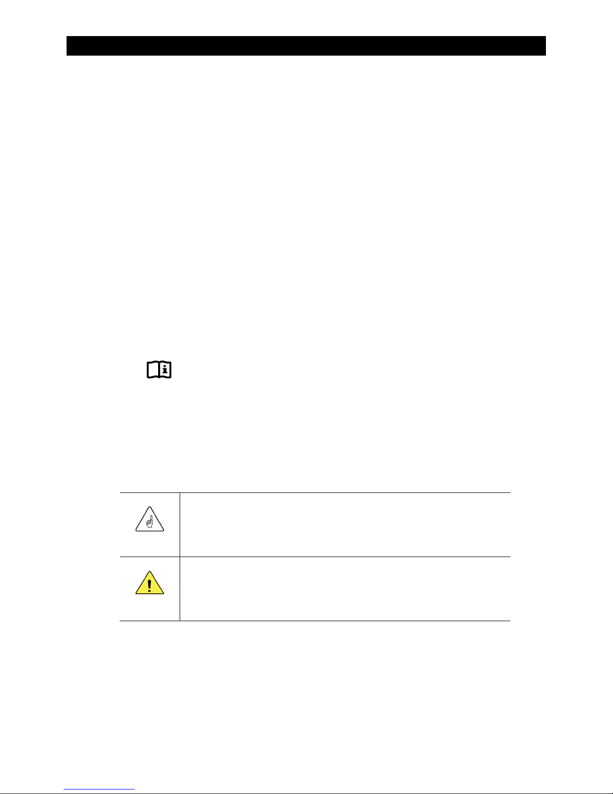
Dimensions
Length 16.25” (41 cm)
Width
8.25”
12” (30.5 cm)
21 cm)
with Turbo
13”
Height
with DCC
Height
33 cm)
Figure 4 Dimensions
16
900-0166-01-01 Rev A
Page 17
Commissioning
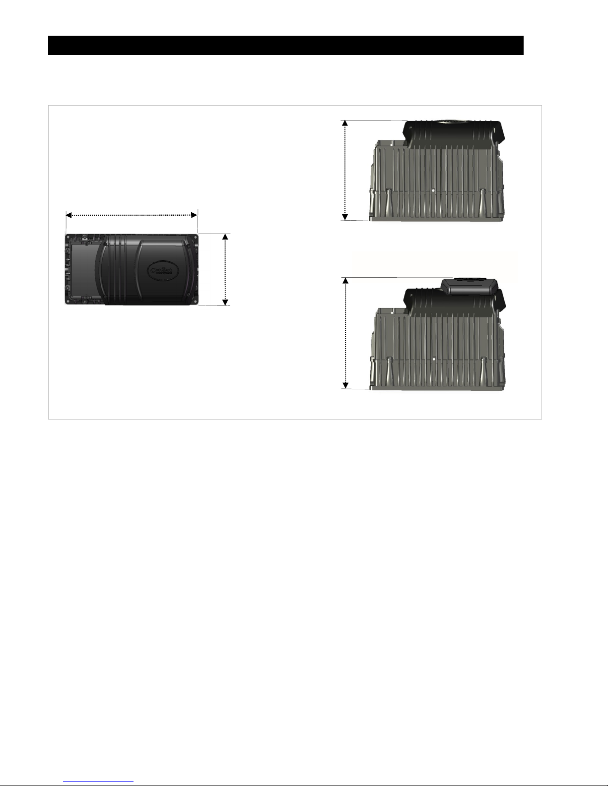
Terminals and Ports
DC TERMINALS
These terminals connect
to the battery cables and
See page 20 for instructions.
CONTROL WIRING TERMINAL BLOCK
These terminals receive control wires for a
variety of functions including generator control.
See pages 26 and 28 for instructions and the
Operator’s Manual for more information.
The Terminal Block can be unplugged from the
AC board for convenience. While installed,
keep screws tight and the block itself secured
tightly to the AC board to prevent malfunction.
These terminals receive wires for a manual
on/off switch to control the inverter.
The jumper alongside these terminals
overrides them and turns the inverter on.
(See page 26 for instructions.) With the
jumper installed, a switch cannot turn the
inverter off, but the system display can turn it
off or on. The system display cannot turn it on
AUX OUTPUT (AUX+/AUX-)
These terminals deliver 12 Vdc up to
0.7 amps (8.4 watts). The output can be
switched on and off for many functions.
The default function is to drive a cooling fan or
the Turbo Fan. See page 26 for details.
The functions for the AUX output can be
programmed using the system display.
the DC system.
INVERTER ON/OFF
ON/OFF JUMPER
if the jumper is not installed.
Figure 5 Terminals, Ports, and Features
NOTE
The
inverter is given an external
:
NVERTER ON/OFF
I
jumper is installed to the
OFF
LED INDICATORS
These indicators display the inverter status and battery voltage.
The three B
The green I
The yellow A
The red E
See the Operator’s Manual for more information.
command at the same time. Its initial state is Off.
DC and AC
GROUND TERMINALS
These terminals connect to
a grounding system for
both batteries and AC. See
page 18 for instructions.
AC TERMINAL BLOCK
These terminals receive AC
input and output wires. See
page 23 for instructions.
XCT+/XCT-
Non-operational
terminals. Do not
connect anything to them.
MATE/HUB and RTS
PORTS
These ports receive the RJ45
and RJ11 plugs from the
system display and Remote
Temp Sensor. See page 26
for instructions.
The ports are mounted
sideways. When viewed from
the left side, they appear as
shown below.
AUX LED INDICATOR
Orange LED indicator turns on
when 12 Vdc output is present.
on DC voltage. They provide a very general idea of battery state.
A Warning is an alert for a problem that is not severe enough for
shutdown. An Error usually accompanies inverter shutdown.
ATTERY LED indicators (green, yellow, and red) are based
NVERTER LED indicator shows if the inverting function is on.
C IN LED indicator shows if an AC source is present.
RROR LED indicator shows either a Warning or an Error.
N
position during manufacture, but the FXR
O
900-0166-01-01 Rev A
17
Page 18

Installation
Wiring
It will be necessary to remove knockouts from the AC Plate to run wires. The AC Plate has one
knockout of ½” size and two knockouts of ¾” size. Install appropriate bushings to protect the wires.
Use copper wire only. Wire must be rated at 75°C or higher.
Grounding
WARNING: Shock Hazard
This unit meets the IEC requirements of Protection Class I.
The unit must be connected to a permanent wiring system that is grounded according to
the IEC 60364 TN standard.
The input and output circuits are isolated from ground. The installer is responsible for
system grounding according to all applicable codes.
For safety, the neutral and ground conductors should be mechanically bonded. OutBack
does not bond these conductors within the inverter. Some codes require the bond to be
made at the main panel only. Make sure that no more than one bond is present in the AC
system at any time.
WARNING: Shock Hazard
For all installations, the negative battery conductor should be bonded to the grounding system
at only one point. If the OutBack GFDI is present, it provides the bond.
IMPORTANT:
Most OutBack products are not designed for use in a positive-grounded system. If it is
necessary to build a positive-grounded system with OutBack products, see the
Grounding
applications note at
www.outbackpower.com
.
Positive
Table 4 Ground Conductor Size and Torque Requirements
Terminal Location Minimum Conductor Size Torque Requirements
Central AC Terminals #10 AWG (0.009 in²) or 6 mm² 25 in-lb (2.8 Nm)
DC Box Lug #6 AWG (0.025 in²) or 16 mm² 45 in-lb (5.1 Nm)
Table 4 contains OutBack’s recommendations for minimum safe cable sizes. Other codes may
supersede OutBack’s recommendations. Consult applicable codes for final size requirements.
18
900-0166-01-01 Rev A
Page 19

Commissioning
The inverter’s DC ground is a box lug located next to the negative DC battery terminal. This lug
accepts up to 1/0 AWG (70 mm² or 0.109 in²) wire. Local codes or regulations may require the DC
ground to be run separately from the AC ground. Also, if present, it will be necessary to remove the
DC Cover or Turbo Fan before making the ground connection. (See page 22.)
Box Lug
Figure 6 DC Ground Lug
CHASSIS GROUND/PE
The two
HASSIS GROUND
C
terminals
/PE
are electrically common. If connecting to an
external ground bus, only one terminal
needs to be used. The other terminal may
be used if connecting to a device with its
own ground wire, such as a generator.
900-0166-01-01 Rev A
Figure 7 Chassis Ground/PE
19
Page 20

Installation
DC Wiring
Table 5 DC Conductor Size and Torque Requirements
WARNING: Shock Hazard
Use caution when working in the vicinity of the inverter’s battery terminals.
CAUTION: Equipment Damage
Never reverse the polarity of the battery cables. Always ensure correct polarity.
CAUTION: Fire Hazard
The installer is responsible for providing overcurrent protection. Install a circuit
breaker or overcurrent device on each DC positive (+) conductor to protect the
DC system.
Never install extra washers or hardware between the mounting surface
and the battery cable lug. The decreased surface area can build up heat.
See the hardware diagram on page 21.
IMPORTANT:
The DC terminals must be encased in an enclosure to meet the requirements of
some local or national codes.
Table 5 contains OutBack’s recommendations for minimum safe cable sizes.
Other codes may supersede OutBack’s recommendations. Consult applicable
codes for final size requirements.
Inverter Nominal DC Amps
(Minimum, per breaker) (Derated 125%)
FXR2012A 200 4/0 AWG (120 mm²) or 0.186 in² 250 Adc
VFXR2812A 280 4/0 AWG (120 mm²) or 0.186 in² 250 Adc
FXR2524A 125 2/0 AWG (70 mm²) or 0.109 in² 175 Adc
VFXR3524A 175 4/0 AWG (120 mm²) or 0.186 in² 250 Adc
FXR3048A 75 1/0 AWG (70 mm²) or 0.109 in² 125 Adc
VFXR3648A 90 1/0 AWG (70 mm²) or 0.109 in² 125 Adc
Terminal Location Torque Requirements
Inverter DC Terminals 60 in-lb (6.9 Nm)
Battery Terminals See battery manufacturer’s recommendations
Conductor Size
(Minimum)
2
Breaker Size
(Minimum)
When installing DC cables:
Battery positive (+) and negative (–) cables should be no longer than 10 feet (3 meters) each. This helps
to minimize voltage loss and other possible effects.
Turn off DC circuit breakers before proceeding.
Tie, tape, or twist cables together to reduce self-inductance. Run positive and negative cables through
the same knockouts and conduit.
The inverter’s battery terminal is a threaded stud which accepts a ring terminal lug. Use crimped and
sealed copper ring lugs with 5/16 inch (0.79 cm) holes, or use compression lugs.
Install all overcurrent devices on the positive cable.
2
Cable sizes are for each inverter in a system. In a system with multiple inverters, each inverter requires its own cables and overcurrent
devices of the size indicated.
20
900-0166-01-01 Rev A
Page 21

Commissioning
To install DC cables and hardware:
1. Install all DC cables.
2. Do not install hardware in a different order from Figure 8. The battery cable lug should be the
first item installed on the stud. It should make solid contact with the mounting surface.
3. Do not close the main DC disconnect until wiring is complete and the system is prepared
for commissioning.
M8 x 1.25 Stud
13 mm Nut
Flat Washer
Mounting Surface
Insulator
Figure 8 Required Order of Battery Cable Hardware
Lock Washer
Battery Cable Lug
CAUTION: Fire Hazard
Never install extra washers or hardware between the mounting surface and the battery
cable lug. The decreased surface area can build up heat.
4. Install the battery terminal covers. These are made of stiff plastic with a snap-on design.
REMOVAL SLOT
If it is necessary to remove the covers,
remove carefully using a flat screwdriver.
Insert the screwdriver into the slot on the
side of each cover and unsnap the cover.
Figure 9 Battery Terminal Covers
900-0166-01-01 Rev A
21
Page 22

Installation
DC Cover or Turbo Fan Attachment
COVER ATTACHMENT
FXR inverters are equipped with either the
DC Cover or the Turbo Fan. To attach
either cover, put the cover in place and
insert a screw at each corner using a
Phillips screwdriver. Make certain the red
and black battery terminals are installed
before attaching the cover.
As part of attaching the Turbo Fan, follow
the wiring instructions in Figure 11.
Figure 10 DC Cover Attachment
TURBO FAN WIRING
Install the wires in the AC Wiring Compartment to
make the Turbo Fan operational. The
UX
– terminals receive the red (+) and black (–)
A
UX
and
A
+
wires. Tighten with a screwdriver.
To safely run the wires into the AC compartment,
pass the wires through the notch in the
compartment cover.
Notch
Edge of Cover
Compartment
If necessary, the green terminal block can be
unplugged by pulling it gently away from the AC board.
Make certain the
correct for proper fan operation.
Figure 11
Turbo Fan Wiring
If it is necessary to remove the Turbo Fan:
1. Remove the screws at the four corners of the Turbo Fan.
2. Remove the compartment cover.
3. Unscrew the
A
UX
+ and
UX
– terminal screws.
A
4. Remove the wires.
5. Remove the Turbo Fan.
UX
programming is
A
22
900-0166-01-01 Rev A
Page 23

f
Commissioning
AC Wiring
WARNING: Shock Hazard
The neutral and ground conductors should be mechanically bonded.
Ensure there is no more than one AC neutral-ground bond at any time.
Local or national codes may require the bond to be made at the main panel only.
IMPORTANT:
The installer is responsible for providing overcurrent protection. The AC input
and output may need to be protected with branch-rated circuit breakers of
maximum 60 Aac size to meet applicable code requirements.
Applicable codes may prevent grid-interactive inverters from using an input circuit
breaker larger than 40 amps. Confirm local requirements before installation.
WARNING: Fire Hazard
Do not install these inverters using a load center that has multiwire branch circuits.
IMPORTANT:
This page contains OutBack’s recommendations for minimum safe cable sizes. Other
codes may supersede OutBack’s recommendations. Consult applicable codes for final
size requirements.
All system wiring must comply with national and local codes and regulations.
The FXR inverter’s AC terminal block has six positions for AC wires. The terminals will accept
conductor sizes up to #6 AWG (16 mm²) or 0.021 in².
AC HOT OUT
The
terminal connects to the
output load panel.
The terminal can carry
up to 60 amps using the
inverter’s transfer relay.
Size the output wiring
and protective devices
according to the size o
the loads and the
applicable code.
HOT OUT
AC
AC HOT IN
AC
HOT IN
terminal brings current from the AC source. It powers both battery
The
charger and loads. Use the source size to determine actual current draw. Size the
input wiring and protective devices accordingly. To support the inverter’s maximum
current draw of 60 Aac, use conductors of #6 AWG (16 mm²) or 0.021 in² size.
NEUTRAL
The two
are electrically common.
If connecting to an external
neutral bus, only one
terminal needs to be used.
An external neutral bus is
often located in the main
electrical panel.
Use the other terminal if
connecting to a device that
has its own neutral wire,
such as a generator.
EUTRAL
N
terminals
Figure 12 AC Terminals
900-0166-01-01 Rev A
23
Page 24

Installation
AC Sources
The inverter has a single set of AC terminals which are intended to connect to a single AC source.
It cannot be directly wired to more than one AC source at the same time.
If multiple sources are used, it is usually required to have a selector switch that changes from one
to the next. The switch should be the “break before make” type which disconnects from one source
before contacting another. This prevents the risk of connecting to two out-of-phase sources at the
same time or connecting them to each other.
Utility Grid Generator
GND NEU HOT
GND NEU HOT
Single-Pole
Double-
Throw
Switch
Inverter
NEU HOT (internal connections)
Internal
Transfer Relay
OUTPUT
NEU
GND
Loads
Figure 13 AC Sources
The inverter’s transfer relay is normally set to provide inverter power to the output. This is shown in
Figure 13, where the internal transfer relay is switched to the inverter function.
Utility Grid
GND NEU HOT GND NEU HOT
Generator
Single-Pole
Double-
Throw
Switch
Inverter
NEU HOT (internal connections)
Internal
Transfer Relay
OUTPUT
NEU
Load
GND
Figure 14 AC Sources and Transfer Relay
When an AC source is connected and accepted, the internal transfer relay switches to transfer the
AC source power to the loads. Figure 14 shows the utility grid switch closed. The internal transfer
relay has switched accordingly so that the loads receive utility power. (See the
for the inverter’s acceptance criteria.)
NOTE
The use of a GFCI-equipped AC source to power either the
recommended.
:
RID
EN
or
G
input is not
G
Operator’s Manual
24
900-0166-01-01 Rev A
Page 25

Commissioning
ON and OFF Wiring
NVERTER ON/OFF
The
I
This jumper parallels the two
jumper bridges two pins.
NVERTER ON/OFF
I
terminals on the Control Wiring Terminal Block.
If either connection is closed, this sets the inverter
to On as long as the internal programming has
not been set to Off with the system display. (The
inverter is given an external
command in the
OFF
factory. Its initial state will be Off.)
An inverter in the Off state will not invert.
However, it may still transfer power to loads and
charge batteries from an AC source.
Jumper Off
Jumper On
If the system display is not present:
To turn the inverter initially On, remove the jumper briefly and then replace it. This requires
long-nose pliers or a similar tool. (This will change the internal programmed state to On.)
After this, removing the jumper will immediately turn the inverter Off.
Once the jumper has been removed, the
NVERTER ON/OFF
I
terminals on the Control Wiring
Terminal Block can be used to wire a manual on/off switch or an emergency shutoff.
Figure 15 ON/OFF Jumper and Connections
900-0166-01-01 Rev A
25
Page 26

Installation
p
Accessory Wiring
The AC Wiring Compartment Board has ports
for both the Remote Temperature Sensor
(RTS) and the system display. The system
display port is labeled
ATE/HUB
M
.
RTS cable
(RJ11, 4-conductor,
telephone)
System Display cable
(RJ45, 8-conductor, CAT5
non-crossover)
RTS port
MATE/HUB port
See the Operator’s
Manual for more
information on
the RTS.
If a HUB Communications Manager is used, it occupies the inverter’s
ATE/HUB
M
port. The system display plugs into the HUB product.
Inverters plug into ports 1 and above. Charge controllers and other
devices plug into unassigned ports not used by inverters.
Additional
ports
MATE
ort
See
Stacking
See the HUB product literature for other devices.
on page 31 for information on connecting inverters.
ATE
:
ATTERY TEMP
ports, make certain to apply silicone grease to
/HUB
B
and
NOTE
When first installing cables on the
M
the connections. A packet is provided with the inverter.
Figure 16 Accessory Connections
AUX Wiring
The AUX+ and AUX– terminals are a switched 12 Vdc supply. The AUX can respond to different
criteria and control many functions. These include cooling fans, vent fans, load diversion, fault
alarms, and the Advanced Generator Start (AGS) function.
The terminals can supply up to 0.7 amps at 12 Vdc (8.4 watts). This is sufficient to drive a small
fan or a relay controlling a larger device. The terminals accept wire up to #14 AWG (2.5 mm²).
The
UX
circuit contains electronic overcurrent protection, which resets after being overloaded.
A
No additional fuses are required for the
The default setting for the A
(See Figure 17.) The A
UX
UX
output can only control one function at a time. It cannot be used for
anything else if the Turbo Fan is connected.
The control logic for the
or another location. FXR
UX
output may be located in the inverter or it may be in the system display
A
UX
functions are located in the inverter and are described accordingly.
A
Although inverter-based functions require the system display for programming, they will function
even if it is removed. However, AGS programming is located within the system display even though
it uses the FXR
UX
terminals. It will not work if the display is removed. (Other devices may also
A
be able to control the terminals.) For generator control, see page 28.
26
UX
terminals.
A
output is to control the Turbo Fan included with sealed models.
900-0166-01-01 Rev A
Page 27

Commissioning
In this example, the
wires on the fan are connected to the
Fan
UX
directly drives a 12-volt vent fan. The + and –
A
UX
and
+
A
AUX–
terminals.
Figure 17 AUX Connections for Vent Fan (Example)
In this example, the
UX
to the
and
+
A
the relay diverts the excess wind power to a water heating element.
UX
output drives a relay that diverts wind power. The relay’s coil is connected
A
terminals. When the
AUX–
UX
output closes the relay (based on battery voltage),
A
A
UX LED INDICATOR
The A
UX indicator
illuminates when the A
output becomes active.
UX
NOTE: Relays and elements shown
are examples only and may vary
depending on the installation.
Figure 18 AUX Connections for Diversion (Example)
Turbine
Relay
Element
900-0166-01-01 Rev A 27
Page 28

Installation
Generator Control
The
function can be
UX
terminals can provide a signal to control an automatic-start generator. The control
A
Advanced Generator Start
(AGS), which is situated in the system display. AGS
can start the generator using settings from the system display, or it can use battery readings from
the FLEXnet DC battery monitor. Note that AGS cannot be used if the system display is removed.
Alternately, the control function can be
Gen Alert
, which is a simpler function based directly in the
FXR inverter. The choice of function depends on system needs and the capabilities of each device.
The generator must be an electric-start model with automatic choke. It is recommended to have
“two-wire” start capability. A two-wire-start generator is the simplest type, where the cranking and
N
starting routine is automated. It usually has a single switch with two positions that is turned
start,
FF
to stop.
O
O
to
Two-Wire Start
The 12 Vdc signal provided by the
signal. It is possible to send a 12-Vdc signal directly to the generator. However, this should never
be done if it connects the
use the
UX
terminals to energize the coil of a 12 Vdc automotive or similar relay.
A
UX
output directly to the generator’s own battery. It is more common to
A
The OutBack FLEXware Relay Assembly depicted in Figure 19 is sold for this purpose. The relay
contacts can serve in place of the generator’s start switch. The battery shown below ( ) is
depicted for clarity. In most cases the battery is part of the generator’s internal starting circuit and is
not an external component.
UX
output can be switched on and off to provide a start
A
The drawing below is one example of a possible arrangement. Specific arrangements, relays, and
other elements depend on the requirements of the installation and of the generator.
Relay
Coil
Relay
Contacts
Generator
Battery
Starting
Terminals
Two-Wire-Start
1
Generator
1
Figure 19 Two-Wire Generator Start (Example)
28
900-0166-01-01 Rev A
Page 29

Three-Wire Start
A “three-wire-start” generator has two or more starting circuits. It usually has a separate switch or
position for cranking the generator. A generator with three-wire start has fewer automated functions
than a two-wire-start generator. It usually requires multiple controls for starting, running, or
Commissioning
stopping. The
two-wire conversion kit.
UX
terminals cannot control this type of generator without using a three-wire to
A
Atkinson Electronics
(http://atkinsonelectronics.com)
is one company that makes these kits. The
Atkinson GSCM-Mini is intended to work with OutBack inverters.
The drawing below is one example of a possible arrangement. Specific arrangements, relays, and
other elements depend on the requirements of the installation and of the generator.
12V AUX
Terminals
Figure 20 Three-Wire Generator Start (Example)
900-0166-01-01 Rev A 29
Atkinson
GSCM-Mini
Three-Wire-Start
Generator
Page 30

Installation
r
AC Configurations
Single-Inverter
When installing an inverter AC system, the following rules must be observed.
All overcurrent devices must be sized for 60 Aac or less.
All output wiring and circuit breakers must be sized appropriately for loads and inverter power.
The AC input (generator or utility grid) must be single-phase and the proper voltage and frequency.
LEGEND
Hot
Neutral
Ground
TBB = Terminal Bus Bar
MATE3s
CAT5 Cable
AC Source
(Utility Grid or AC Generator)
AC Conduit
NEU GND
AC
Neutral
IN
HUB/
MATE
HOT
AC
Hot
IN
Inverter/Charger
AC
Neutral
OUT
GROUND
AC
Hot
OUT
NOTES:
1. Neutral (common) conductor may be
connected from only one inverter
neutral terminal to a common bus bar
in the AC conduit box.
2. Colors depicted here may be different
from wiring standards.
Input
Circuit
Breake
Ground TBB
(may be within
AC Conduit Box)
Primary System
Ground
Figure 21 Single-Inverter Wiring
30
NEU GND HOT
AC Loads
Mechanical
Interlock
Output
Circuit
Breaker
Bypass
Circuit
Breaker
900-0166-01-01 Rev A
Page 31

Commissioning
Multiple-Inverter AC Installations (Stacking)
Installing multiple inverters in a single AC system allows larger loads than a single inverter can
handle. This requires “stacking”. Stacking inverters refers to how they are wired within the system
and then programmed to coordinate activity. Stacking allows all units to work together as a
single system.
Examples of stacking configurations include “series”, “parallel”, “series/parallel”, and “three-phase”.
Stacking Connections
Stacking requires an OutBack HUB10.3 communications manager and a system display.
Make all interconnections between the products with CAT5 non-crossover cable.
HUB10.3
Communications
Manager
Additional Ports
Port 1
MATE
Port
MATE3s
System Display
Figure 22 OutBack Communications Manager and System Display
Each inverter must be assigned a stacking mode, “master” or “slave” of some type depending on
the configuration.
The master inverter provides the primary output phase, L1 (or Phase A in a three-phase system).
Other inverters in the system base their phase on that of the master inverter. If the master shuts off, all
other inverters also shut off. The master must sense and connect to an AC source before other inverters
can connect.
~ In a parallel-stacked system, the master tends to be the most heavily used unit.
~ “Subphase master” inverters are used to control other phases in series or three-phase systems.
A subphase master inverter operates semi-independently of the master inverter. Although the
master inverter sets the phase relationship, the subphase master creates an output independent of
the master.
~ The master on the L1 (or A phase) output cannot measure loads and voltages on any other output.
The subphase masters for each of the other outputs perform monitoring and regulation for the phase
they control.
~ In a series or series/parallel-stacked system, a subphase master is required for the L2 output.
~ In a three-phase system, subphase masters are required for both the B and C phases.
A slave inverter does not create an independent output. It simply assists the master or subphase master
by adding power to the output as needed.
~ The Power Save function can place slave inverters in “Silent” mode when not in use. They are
activated by the master or subphase master when required.
900-0166-01-01 Rev A
NOTE
The FW-X240 and similar transformers are not used for load balancing of stacked
FXR inverters.
:
31
Page 32

Installation
Each inverter is assigned to a particular phase when assigned a port on the HUB10.3
communications manager. Port assignments will vary with the system. The master must be
plugged into port 1. In parallel stacking, any slave inverter can use any other port, beginning with
port 2. In series or three-phase stacking, the port assignments are very specific. See the HUB10.3
literature for more information. Regardless, it is important to keep track of units and ports for
programming purposes.
Programming uses the system display to assign a status and stacking value to the inverter on each
port. As long as the master is plugged into port 1, these assignments can be changed as needed.
IMPORTANT:
The master inverter must always be connected to port 1 on the
communications manager. Connecting it elsewhere, or connecting a
slave to port 1, will result in backfeed or output voltage errors which will
shut the system down immediately.
All stacked FXR inverters must have the same firmware revision. If
inverters are stacked with different firmware revisions, any unit with a
revision different from the master will not function. The system display
will display the following message:
An inverter firmware mismatch has been detected. Inverters X, Y,
3
Z
are disabled. Visit www.outbackpower.com for current inverter
firmware.
FXR-class inverters cannot be stacked with FX-class inverters. If more
than one model class or series is stacked, any inverter different from the
master will not invert or connect to an AC source. The system display
will register an Event in the log. It will display the following message:
A model mismatch has been detected. Inverters are incompatible.
Inverters X, Y, Z
Installing multiple inverters without stacking them (or stacking them
incorrectly) will result in similar errors and shutdown.
Although stacking allows greater capacity, the loads, wiring, and
overcurrent devices must still be sized appropriately. Overloading may
cause circuit breakers to open or the inverters to shut down.
An AC source should provide input to all inverters on all phases.
3
are disabled. Match all models before proceeding.
3
The port designations for the mismatched inverters are listed here.
32
900-0166-01-01 Rev A
Page 33

Stacking Configurations
Commissioning
Series Stacking (Dual-Stack)
In series stacking, two inverters create two separate 120 Vac4 output phases. One phase is the
master. The second inverter is a subphase master. It creates a 120 Vac output that is intentionally
180° out of phase with the master. Each of these outputs can be used to power a separate set of
120 Vac loads. Collectively they form a “split-phase” configuration. This configuration produces
240 Vac, which can be used to power 240 Vac loads when both inverters work together.
The two outputs operate independently of each other. The 120 Vac loads on each output cannot exceed
a given inverter’s size. One inverter cannot assist on the opposite phase.
Both inverters must be the same model.
See page 37 when stacking in series with more than two inverters (series/parallel stacking).
LOAD PANEL
Master
2.0 kVA
2.0 kVA 120 Vac
L2 Phase Master
2.0 kVA 120 Vac
120 Vac
2.0 kVA
120 Vac
OR
4.0 kVA
240 Vac
Figure 23 Example of Series Stacking Arrangement
When installing a series inverter system, observe the following rules.
Series stacking requires both the system display and the communications manager. See the HUB10.3
literature for any required jumper configurations.
The master must be connected to communications manager port 1. It is programmed as
Other inverters must not be assigned as the master.
The second inverter must be programmed as
All wiring and circuit breakers must be sized appropriately for loads and inverter power.
The AC input (generator or utility grid) must be a split-phase source of the proper voltage and frequency.
When wiring the AC source to the inverters, local codes may require the inverter circuit breakers to be
located at the bottom of the main panel. This prevents overloading of the AC bus.
NOTE
: The FW-X240 and similar transformers are not used for load balancing of stacked FXR inverters.
4
Output voltages may vary with regional voltage standards.
900-0166-01-01 Rev A
L2 Phase Master
Master
. It must be connected to port 7.
.
33
Page 34

Installation
r
r
)
HUB 10.3
10 9 8 7 6 5 4 3 2 1 MATE
MATE3s
CAT5 Cables
AC Source
(Utility Grid or AC Generator)
AC Conduit Box
GND
Neutral
TBB
Hot L1
TBB
Hot L2
TBB
Primary
System
Ground
Ground TBB
(may be within
AC Conduit Box
AC
Neutral
IN
AC
Neutral
OUT
HUB/
MATE
Inverter
L1 Master
GND
AC
Hot IN
(L1)
AC
Hot
OUT
Input
Circuit
Breaker
AC
Neutral
IN
Inverter
L2 Subphase
Master
AC
Neutral
OUT
Mechanical
Output
Circuit
Breake
HUB/
MATE
GND
AC
Hot IN
(L2)
AC
Hot OUT
(L2)
Interlock
Input
Circuit
Breaker
Bypass
Circuit
Breake
LEGEND
Hot L1
Hot L2
Neutral
Ground
TBB = Terminal Bus Bar
Figure 24 Series Wiring (Two Inverters)
34
GND
Neutral
TBB
AC Loads
Hot L1
TBB
Hot L2
TBB
NOTES:
1. Neutral (common) conductor
may be connected from only
one neutral terminal (per
inverter) to a common bus
bar in the AC conduit box.
2. Colors shown here may be
different from wiring
standards.
900-0166-01-01 Rev A
Page 35

Commissioning
Parallel Stacking (Dual-Stack and Larger)
In parallel stacking, two or more inverters create a single, common 120 Vac5 bus.
The slave outputs are controlled directly by the master and cannot operate independently.
All inverters share a common input (AC source) and run loads on a common output.
Slave inverters can go into Silent mode when not in use. The master will activate individual slaves based
on load demand. This reduces idle power consumption and improves system efficiency.
Up to ten inverters may be installed in a parallel arrangement. The example on this page shows three
inverters. The wiring diagram on the next page shows four. All inverters must be the same model.
LOAD
PANEL
Master Slave Slave
6.0 kVA
2.0 kVA 120 Vac
2.0 kVA 120 Vac
2.0 kVA 120 Vac
120 Vac
Figure 25 Example of Parallel Stacking Arrangement (Three Inverters)
When installing a parallel inverter system, observe the following rules.
Parallel stacking requires both the system display and the communications manager. See the HUB10.3
literature for any required jumper configurations.
The inverter that is mounted physically lowest is always the master and is programmed as
Master.
Mounting below the other inverters allows the master to avoid heat buildup and remain relatively cool as it
sees the greatest duty cycle.
The master must be connected to port 1 of the communications manager. Other inverters must not be
assigned as master.
All slave inverters, regardless of number, should be assigned as
during programming. Slaves can
Slave
be connected to any port numbered 2 and above.
All wiring and circuit breakers must be sized appropriately for loads and inverter power.
The AC input (generator or utility grid) must be a single-phase source of the proper voltage and
frequency.
When wiring the AC source to the inverters, local codes may require the inverter circuits to be located at
the opposite end of the panel from the main circuit breaker. This prevents overloading of the AC bus.
5
Output voltages may vary with regional voltage standards.
900-0166-01-01 Rev A
35
Page 36

Installation
MATE3s
HUB 10.3
10 9 8 7 6 5 4 3 2 1 MATE
CAT5 Cables
AC
Neutral
IN
Inverter
L1 Master
AC
Neutral
OUT
GND
HUB/
MATE
GND
AC
Hot
IN (L1)
AC
Hot
OUT
Input
Circuit
Breaker
Neutral
Neutral
AC Source
(Utility Grid or
AC Generator)
AC Conduit
Neutral
TBB
AC
IN
HUB/
MATE
Hot L1 TBB
AC
Hot
IN (L1)
Input
Circuit
Breaker
Neutral
AC
IN
HUB/
MATE
Inverter Inverter
L1 Slave
AC
OUT
GND
AC
Hot
OUT
L1 Slave
AC
Neutral
OUT
GND
LEGEND
TBB = Terminal Bus Bar
Input
Circuit
Breaker
AC
Hot
IN (L1)
AC
Neutral
IN
Inverter
L1 Slave
AC
Hot
OUT
AC
Neutral
OUT
Hot L1
Neutral
Ground
HUB/
MATE
GND
Input
Circuit
Breaker
AC
Hot
IN (L1)
AC
Hot
OUT
Ground TBB
(may be within
AC Conduit Box)
Primary
System
Ground
GND Hot L1
Neutral TBB
Figure 26 Parallel Wiring (Four Inverters)
36
AC Loads
Mechanical
Interlock
Output
Circuit
Breakers
Bypass
Circuit
Breakers
NOTES:
1. Neutral (common) conductor may be
connected from only one neutral
terminal (per inverter) to a common
bus bar in the AC conduit box.
2. Colors shown here may be different
from wiring standards.
900-0166-01-01 Rev A
Page 37

Commissioning
Series/Parallel Stacking (Quad-Stack or Larger)
In series/parallel stacking, inverters create separate 120 Vac6 output phases and 240 Vac
collectively, as in series stacking. However, in this configuration, each output uses inverters in
parallel. One output contains the master; the other uses a subphase master. Each output has at
least one slave.
The 120 Vac loads on each output can exceed the size of a single inverter. They can be powered by all
the inverters on that output.
The slave outputs are controlled directly by their respective master inverters. They cannot operate
independently. The slaves can go into Silent mode when not in use.
Up to eight inverters may be installed in series/parallel. All inverters must be the same model.
LOAD PANEL
3 kVA 120 Vac
3 kVA 120 Vac
Master Slave
3 kVA 120 Vac
L2 Phase
Master
3 kVA 120 Vac
Slave
6 kVA
120 Vac
6 kVA
120 Vac
OR
12 kVA
240 Vac
Figure 27 Example of Series/Parallel Stacking Arrangement (Four Inverters)
When installing a multiple-inverter series/parallel system, observe the following rules.
Series/parallel stacking requires both the system display and the communications manager. See the
HUB10.3 literature for any required jumper configurations.
The inverter that is mounted physically lowest is always master and is programmed as
Master
Mounting below the other inverters allows the master to avoid heat buildup and remain relatively cool as it
sees the greatest duty cycle.
The master must be connected to port 1 of the communications manager. Other inverters must not be
assigned as master.
Any other inverter on the L1 output (parallel with the master) should be assigned as
Slave
programming. These can be connected to ports 2 through 4. L1 inverters cannot use other ports.
The subphase master for the L2 output must be assigned as
L2 Phase Master
. It must be connected
to port 7.
Any other inverter on the L2 output (parallel with the subphase master) should be assigned as
during programming. These can be connected to ports 8 through 10. L2 inverters cannot use other ports.
All wiring and circuit breakers must be sized appropriately for loads and inverter power.
The AC input (generator or utility grid) must be a split-phase source of the proper voltage and frequency.
When wiring the AC source to the inverters, local codes may require the inverter circuits to be located at
the opposite end of the panel from the main circuit breaker. This prevents overloading of the AC bus.
.
during
Slave
NOTE
: The FW-X240 and similar transformers are not used for load balancing of stacked FXR inverters.
6
Output voltages may vary with regional voltage standards.
900-0166-01-01 Rev A
37
Page 38

Installation
MATE3s
HUB 10.3
10 9 8 7 6 5 4 3 2 1 MATE
CAT5 Cables
AC
HUB/
Neutral
MATE
IN
Inverter
L1 Master
AC
Neutral
GND
OUT
GND
AC
Hot IN
(L1)
AC
Hot OUT
(L1)
Input
Circuit
Breaker
Neutral
AC Source
(Utility Grid or
AC Generator)
AC Conduit Box
HUB/
MATE
Hot L1
AC
Hot IN
(L1)
Neutral
AC
IN
Inverter
L1 Slave
AC
Neutral
OUT
GND
AC
Hot OUT
(L1)
Hot L2
Input
Circuit
Breaker
AC
Neutral
IN
Inverter
L2 Subphase
AC
Neutral
OUT
HUB/
MATE
Master
Hot OUT
GND
TBB = Terminal Bus Bar
Input
Circuit
Breaker
AC
Hot IN
(L2)
AC
(L2)
Neutral
LEGEND
AC
HUB/
MATE
IN
Inverter
L2 Slave
AC
Neutral
GND
OUT
Hot L1
Hot L2
Neutral
Ground
AC
Hot IN
(L2)
AC
Hot OUT
(L2)
Input
Circuit
Breaker
Ground TBB
(may be within
AC Conduit Box)
Primary
System
Ground
Neutral TBB GND
Figure 28 Series/Parallel Wiring
38
AC Loads
Hot L1
Mechanical
Interlock
Output
Circuit
Breakers
Hot L2 TBB
Bypass
Circuit
Breakers
NOTES:
1. Neutral (common) conductor may
be connected from only one neutral
terminal (per inverter) to a common
bus bar in the AC conduit box.
2. Colors shown here may be different
from wiring standards.
900-0166-01-01 Rev A
Page 39

Commissioning
Three-Phase Stacking
In three-phase stacking, inverters create three separate 120 Vac7 output phases in wye configuration.
The three phases (A, B, and C) operate independently of each other. The inverters on one phase cannot
assist another. Several inverters can be installed in parallel on each phase to power all 120 Vac loads on
each of those phases.
The output of each inverter is 120° out of phase from the others. Any two outputs produce 208 Vac
between them. The outputs can be used to power three-phase loads when all inverters work together.
Up to nine inverters, three per phase, may be installed in a three-phase arrangement. (The wiring drawing
on the next page shows only one inverter per phase.) All inverters must be the same model.
LOAD PANEL
Master
2.0 kVA 120 Vac
B Phase Master
2.0 kVA 120 Vac
C Phase Master
2.0 kVA 120 Vac
2.0 kVA
120 Vac
2.0 kVA
120 Vac
2.0 kVA
120 Vac
OR
6.0 kVA
208
Figure 29 Example of Three-Phase Stacking Arrangement (Three Inverters)
LOAD PANEL
Master
2.0 kVA 120 Vac
B Phase
Master
2.0 kVA 120 Vac
C Phase
Master
2.0 kVA 120 Vac
Slave
2.0 kVA 120 Vac
Slave
2.0 kVA 120 Vac
Slave
2.0 kVA 120 Vac
2.0 kVA 120 Vac
2.0 kVA 120 Vac
2.0 kVA 120 Vac
Slave
Slave
Slave
6.0 kVA
120 Vac
6.0 kVA
120 Vac
6.0 kVA
120 Vac
OR
208 Vac
Figure 30 Example of Three-Phase Stacking Arrangement (Nine Inverters)
18.0
kVA
7
Output voltages may vary with regional voltage standards.
900-0166-01-01 Rev A
39
Page 40

Installation
When installing a three-phase system, observe the following rules.
Three-phase stacking requires both the system display and the communications manager. See the
HUB10.3 literature for any required jumper configurations.
The inverter that is mounted physically lowest is always master and is programmed as
Master
.
Mounting below the other inverters allows the master to avoid heat buildup and remain relatively cool as it
sees the greatest duty cycle.
The master must be connected to port 1 of the communications manager. Other inverters must not be
selected as master.
Any other inverter on the Phase A output (parallel with the master) should be assigned as
Slave
during
programming. These can be connected to ports 2 or 3. Phase A inverters cannot use other ports.
The subphase master for the Phase B output must be programmed as
B Phase Master
. It must be
connected to port 4.
Any other inverter on the Phase B output (parallel with the B subphase master) should be assigned as
during programming. These can be connected to ports 5 or 6. Phase B inverters cannot use
Slave
other ports.
The subphase master for the Phase C output must be programmed as
C Phase Master
. It must be
connected to port 7.
Any other inverter on the Phase C output (parallel with the C subphase master) should be assigned as
during programming. These can be connected to ports 8, 9, or 10. Phase C inverters cannot use
Slave
other ports.
All wiring and circuit breakers must be sized appropriately for loads and inverter power.
The AC input (generator or utility grid) must be a three-phase wye configuration source of the proper
voltage and frequency.
When wiring the AC source to the inverters, local codes may require the inverter circuits to be located at
the opposite end of the panel from the main circuit breaker. This prevents overloading of the AC bus.
40 900-0166-01-01 Rev A
Page 41

Commissioning
HUB
10 9 8 7 6 5 4 3 2 1 MATE
CAT5 Cables
MATE3s
GND
AC
HUB/
MATE
AC
Hot IN
(A)
Neutral
IN
Inverter
Phase A Master
AC
Neutral
OUT
GND
AC
Hot OUT
(A)
AC Source
(Utility Grid or AC Generator)
AC Conduit Box
Neutral
TBB
AC
Neutral
IN
HUB/
MATE
Phase A
TBB
Input
Circuit
Breaker
AC
Hot IN
(B)
Inverter
Phase B
Subphase Master
AC
Neutral
OUT
GND
AC
Hot OUT
(B)
Phase B
TBB
Input
Circuit
Breaker
AC
Neutral
IN
Inverter
Phase C
Subphase Master
AC
Neutral
OUT
Phase C
TBB
Input
Circuit
Breaker
HUB/
MATE
GND
AC
Hot IN
(C)
AC
Hot OUT
(C)
Ground TBB
(may be within
AC Conduit Box)
Primary System
Ground
LEGEND
TBB = Terminal Bus Bar
Figure 31 Three-Phase Wiring (Three Inverters)
900-0166-01-01 Rev A
Phase A
Phase B
Phase C
Neutral
Ground
GND
Neutral
TBB
AC
Loads
Phase A
TBB
Phase B
TBB
Phase C
TBB
Mechanical
Interlock
Output
Circuit
Breakers
NOTES:
1. Neutral (common) conductor
2. Colors shown here may be
Bypass
Circuit
Breakers
may be connected from only
one neutral terminal (per
inverter) to a common bus bar
in the AC conduit box.
different from wiring standards.
41
Page 42

Installation
Power Save
IMPORTANT:
In any system that features slave inverters,
Leaving the inverters at the factory default settings (or setting them incorrectly) will cause erratic system
performance. See the FXR Series Inverter/Charger Operator’s Manual for a table of menu items and
settings. See the system display literature for navigation instructions.
Power Save
must be programmed before commissioning.
Each FXR inverter uses 34 watts of idle power while turned on, even if it is not actively inverting or
charging. The
Power Save
function can put part of a parallel system into a “sleep” state (Silent
mode) to minimize the idle consumption. The inverters will activate again when the loads require
power. (The term “Silent” is also used in an unrelated context during battery charging.)
Every time the load increases by an additional 12 Aac, the master inverter activates an additional slave
inverter for assistance. When the load decreases to 4 Aac or less
the master), one slave is deactivated and returns to Silent mode.
The order in which slaves activate (or return to Silent mode) is controlled by programming in the system
display. The inverters are given a “rank”, or level number. Lower rank numbers activate when lesser
loads are applied. Higher ranks only activate when the load increases to a high level.
The lowest-ranked inverters do not enter Silent mode. This includes the master and subphase master
inverters. They remain active unless specifically turned off. These inverters can still enter Search mode.
Master
Slave 1 Slave 3 Slave 2
per active inverter
(as detected by
Minimal load
Increasing load
High load
Maximum load
On
On
On
On
Off
On
On
On
Off Off
Off Off
On Off
On On
Figure 32 Power Save Levels and Loads
The actual watt and ampere thresholds for activating FXR inverters are depicted on the
following pages.
IMPORTANT:
It is highly recommended to use the Profile Wizard in a MATE3-class system display to set up this
function. It is essential to set the slave
off correctly. The Profile Wizard automatically programs the correct priorities.
Power Save Levels
in sequential order so that they turn on and
To set these items manually without the Profile Wizard:
In the system display, the
Power Save Ranking
assign ranks to the inverter on each port. The screen reads
Power Save Level
, depending on the inverter’s stacking designation.
screen uses
Power Save Level
selections to
Master Power Save Level
or
Slave
The stacking designations also control which ports are used on the HUB10.3 communications
manager. The master inverter must be plugged into port 1. In parallel stacking, any slave inverter
can use any other port, beginning with port 2. In series or three-phase stacking, the port
42
900-0166-01-01 Rev A
Page 43

Commissioning
assignments are very specific. They are also different from each other, as illustrated in the
HUB10.3 literature.
Master Power Save Level
of rank numbers is 0 to 10. The default value is 0. The master is normally left at this value.
The Master Power Save Level function is used for the master inverter on Port 1. It is also used for
any subphase masters in a series or three-phase system. The ranking of a subphase master is
treated the same as the master. If the master is set at 0, subphase masters should also be 0.
appears on an inverter which is set as master (the default setting). The range
Slave Power Save Level
appears on an inverter which is set as slave. The range of rank numbers is 1
to 10. (The default value for all ports is 1.)
When subphase master inverters are in use, the slaves for the additional phases are ranked
identically to the slaves on the master phase. If the master inverter has two slaves ranked 1 and 2,
any other phases should also rank their slaves 1 and 2. Slaves on multiple phases should not be
ranked sequentially (1 through 6 and so on). This would cause delays in output.
The ranks are prioritized so that lower-numbered ranks turn on sooner and higher ranks turn on
later. The lowest-ranked inverter does not go silent and remains on unless ordered otherwise.
The lowest-ranked inverter is expected to be the master. The priorities are the same across both
screens. If Port 1 (master) is set at 0 and Port 2 (slave) is set at 1, the slave will turn on later.
Since the
Master
item is the only one that goes to 0, it is easy to ensure that all slave inverters
go silent. (To force all slaves to be active, simply set the master at a higher rank than the slaves.)
Subphase master inverters are set at 0 because all phases must have at least one inverter that
does not enter Silent mode. The slaves for each phase are set identically to each other so that all
phases receive additional power at the same time as needed.
IMPORTANT:
Set the master (or subphase) rank at 0 and arrange the slave ranks in order (1, 2, 3, 4, etc.). Another
order may defeat the purpose of Power Save mode. Leaving the master at 0 makes power available
from the master; the other inverters should not be active. If a slave is ranked lower (prioritized
higher) than the master, that slave will not go silent.
Disregard this rule if the installation requires some slaves to be continuously active.
:
NOTE
IMPORTANT:
Do not give slave inverters the same rank numbers. If, for example, multiple slaves were all ranked
at 1, they would all come on at the same time. Once they came on, the divided load would cause the
master to detect a minimal load on its output, so it would shut off all the slaves, at which point the
master would read a high load again. This could quickly escalate into a rapid on/off cycling of
inverters and could cause long-term system problems.
NOTE
Power Save
charger is activated at once. Initially the master inverter is the only active charger. The batteries will
absorb current up to the maximum for all chargers. When the batteries (and the master) draw more
than 12 Aac, the master will turn on the first slave charger. The batteries will absorb that additional
current and more. The master will then turn on more slaves until all active chargers are operating.
If the master
the only charger. For more information on charging with stacked inverters, see the FXR Series
Inverter/Charger Operator’s Manual.
:
is used by the battery chargers of stacked systems with slave inverters. Not every
Charger AC Limit
is turned to 11 or less, it will not turn on any slaves and will remain
Figure 33 shows a system of four FXR2012A inverters (the master and three slaves). These
inverters in a parallel system with a common load bus.
The captions at the top indicate the ranking of each inverter.
The captions also show the port assignments on the communications manager (1 through 4).
The notations at the bottom show how the inverter are activated in sequence as loads of 12 Aac
are applied.
900-0166-01-01 Rev A
43
Page 44

Installation
Master Slave 1 Slave 3 Slave 2
Port 1
Master Power
Save = 0
<12 Aac On Off Off Off
12 Aac On On Off Off
24 Aac On On On Off
36 Aac On On On On
16 Aac On On On Off
Figure 33 Power Save Priority (Parallel)
The fourth line shows that loads of 36 Aac or more (approximately 4 to 4.5 kW) are present on the
system. This load causes all four inverters to be activated.
The last line shows that the loads are reduced to 16 Aac. Since this load is distributed among four
inverters, the master reads 4 Aac, the lower threshold for Power Save. This causes one slave to enter
Silent mode. The 16 Aac are distributed among the remaining three inverters. If the loads decreased to
12 Aac, a second slave would go silent.
Port 2
Slave Power
Save = 1
Port 3
Slave Power
Save = 2
Port 4
Slave Power
Save = 3
Figure 34 shows a system of six FXR2012A inverters. In this example the inverters have been
stacked in a split-phase system. The master inverter is on the L1 output while a subphase master
is on L2. Each master has two slave inverters.
The captions at the top indicate the ranking of each inverter.
The captions also show the communications manager port assignments. The L1 inverters use ports 1, 2,
and 3. However, the communications manager requires the L2 inverters to use ports 7, 8, and 9.
The notations at the bottom show how the inverters are activated in sequence as loads are applied. The
loads on L1 and L2 are not applied equally, so they are not activated at the same time.
L1 Master L1 Slave 1 L2 Subphase L1 Slave 2
Port 1
Master Power
Save = 0
Port 2
Slave Power
Save = 1
Port 3
Slave Power
Save = 2
Port 7
Master Power
Save = 0
L1 Load L2 Load
9 Aac On Off Off 9 Aac On Off Off
12 Aac On On Off 9 Aac On Off Off
24 Aac On On On 18 Aac On On Off
36 Aac On On On 36 Aac On On On
11 Aac On On Off 7 Aac On Off Off
L2 Slave 1 L2 Slave 2
Port 8
Slave Power
Save = 1
Port 9
Slave Power
Save = 2
Figure 34 Power Save Priority (Split-Phase)
The fourth line shows that loads of 36 Aac or more (approximately 4 to 4.5 kW) are present on both L1
and L2. This load causes all six inverters to be activated.
The last line shows that the loads on L1 are reduced to 11 Aac. This causes one slave to go silent. The
loads on L2 are reduced to 7 Aac, causing two slaves to go silent.
44 900-0166-01-01 Rev A
Page 45

Commissioning
Functional Test
WARNING: Shock Hazard and Equipment Damage
The inverter’s AC and DC covers must be removed to perform these tests. The components are
close together and carry hazardous voltages. Use appropriate care to avoid the risk of electric shock
or equipment damage.
It is highly recommended that all
steps are inapplicable, they can be omitted.
If the results of any step do not match the description, see the Operator’s Manual for troubleshooting.
Pre-startup Procedures
1. Ensure all DC and AC overcurrent devices are opened, disconnected, or turned off.
2. Double-check all wiring connections.
applicable
steps be performed in the following order. However, if
3. Confirm that the total load does not exceed the inverter’s rated power.
4. Inspect the work area to ensure tools or debris have not been left inside.
5. Using an accurate digital voltmeter (DVM), verify battery voltage. Confirm the voltage is correct
for the inverter model. Confirm the polarity.
6. Connect the system display, if present.
CAUTION: Equipment Damage
Incorrect battery polarity will damage the inverter. Excessive battery voltage also may damage the inverter. This
damage is not covered by the warranty.
IMPORTANT:
Prior to programming (see
correct AC operation. The default setting is 60 Hz, but this can be changed to 50 Hz.
), verify the operating frequency of the AC source. This is necessary for
Startup
Startup
To start a single-inverter system:
1. Close the main DC circuit breakers from the battery bank to the inverter. Confirm that the
system display is operational, if present.
2. If a system display is present, perform all programming for all functions. These functions may
include AC input modes, AC output voltage, input current limits, battery charging, generator
starting, and others.
900-0166-01-01 Rev A
45
Page 46

Commissioning
Figure 35 AC Terminals
3. Turn on the inverter using the system display (or external switch, if one has been installed). The
inverter’s default condition is Off. Do not turn on any AC circuit breakers at this time.
4. Using a DVM, verify 120 Vac (or appropriate voltage) between the AC
N
EUTRAL OUT
terminals. (See Figure 35.) The inverter is working correctly if the AC output
HOT OUT
and AC
reads within 10% of 120 Vac or the programmed output voltage.
5. Proceed past the items below to Step 6 on the next page.
To start a multiple-inverter (stacked) system:
1. Close the main DC circuit breakers from the battery bank to the inverters. Repeat for every
inverter present. Confirm that the system display is operational.
With the system display, perform any programming for stacking and all other functions.
These functions may also include AC input modes, AC output voltage, input current limits,
battery charging, generator starting, and others. When stacking in parallel, all slave inverters
will observe the programming settings of the master inverter. They do not need to be
programmed individually. In a MATE3-class system display, the Profile Wizard may be used to
assist programming.
2. Turn on the master inverter using the system display (or external switch, if one was installed).
The inverter’s default state is Off. Do not turn on any AC circuit breakers at this time.
3. Using the system display, temporarily bring each slave out of Silent mode by raising the Power
Save Level of the master. (See page 43.)
As each slave is activated, it will click and create an audible hum. The green
indicator LED on that slave will illuminate.
TATUS INVERTER
S
Confirm that the system display shows no fault messages.
4. Using a DVM, verify appropriate voltage between the AC H
inverter and the AC
HOT OUT
of 120 Vac or the programmed output voltage. Parallel inverters should read close to zero.
Three-phase inverters should read within 10% of 208 Vac or the designated output voltage.
5. When this test is finished, return the master to its previous Power Save Level.
46
900-0166-01-01 Rev A
OT OUT
terminal on the master
terminal on each slave. Series inverters should read within 10%
Page 47

Commissioning
After output testing is completed, perform the following steps:
6. Close the AC output circuit breakers. If AC bypass switches are present, place them in the
normal (non-bypass) position. Do not connect an AC input source or close any AC
input circuits.
7. Use a high-resolution voltmeter to verify correct voltage at the AC load panel.
8. Connect a small AC load and test for proper functionality.
9. Close the AC input circuit breakers and connect an AC source.
Using a high-resolution voltmeter, check the
(or appropriate voltage) from the AC source.
If a system display is present, confirm that the inverter accepts the AC source as appropriate for its
programming. (Some modes or functions may restrict connection with the source. If one of these
selections has been used for the system, it may not connect.) Check the system display indicators
for correct performance.
10. If the charger is activated, the inverter will perform a battery charging cycle after powering up.
This can take several hours. If restarted after a temporary shutdown, the inverter may skip most
or all of the charging cycle. With the system display, confirm that it is charging as appropriate.
11. Test other functions which have been enabled, such as generator start or search mode.
12. Compare the voltmeter’s readings with the system display meter readings. If necessary, the
system display’s readings can be calibrated to match the voltmeter more accurately. Calibrated
settings include AC input voltage, AC output voltage, and battery voltage.
AC
HOT IN
and AC
EUTRAL IN
N
terminals for 120 Vac
Powering Down
These steps will completely isolate the inverter.
To remove power from the system:
1. Turn off all load circuits and AC input sources.
2. Turn off all renewable energy circuits.
3. Turn each inverter Off using the system display or external switch.
4. Turn off the main DC overcurrent devices for each inverter.
Adding New Devices
When adding new devices to the system, first turn off the system according to the
instructions. After adding new devices, perform another functional test, including programming.
Operation
Once the mounting, wiring, and other installation steps are completed, proceed to the
Inverter/Charger Operator’s Manual
Refer to the system display literature for programming instructions and menus.
900-0166-01-01 Rev A 47
Powering Down
FXR Series
.
Page 48

Commissioning
Firmware Updates
IMPORTANT:
All inverters will shut down during firmware updates. If loads need to be run while updating the
firmware, bypass the inverter with a maintenance bypass switch. Communication cables must
remain connected and DC power must remain on. Interrupted communication will cause the
update to fail and the inverter(s) may not work afterward. Inverters automatically update one at
a time beginning with the highest port. Each requires about 5 minutes.
Updates to the inverter’s internal programming are periodically available at the OutBack website
www.outbackpower.com
the same time. All units must be upgraded to the same firmware revision.
See the system display
. If multiple inverters are used in a system, all units must be upgraded at
IMPORTANT:
All stacked FXR inverters must have the same firmware revision. If multiple stacked inverters
are used with different firmware revisions, any inverter with a revision different from the master
will not function. (See the stacking section on page 31.) The system display will show the
following message:
An inverter firmware mismatch has been detected. Inverters X, Y, Z
disabled. Visit
Overview Guide
NOTE:
The MATE3s system display must be used when upgrading the inverter to firmware
revision 001.006.063 or higher.
www.outbackpower.com
for instructions on performing updates.
for current inverter firmware.
8
are
.GIP File Installation for Grid Support
To enable grid support functionality in different parts of the world, it may be necessary to update
the inverter firmware. The .ZIP files for update can be downloaded from the
section of the
Firmware Update
page at
www.outbackpower.com
FXR Grid Support
. Each .GIP file available
with an update contains a “package” of grid support settings associated with different utility
companies or regional standards.
IMPORTANT:
The MATE3s system display is required for this process.
Make certain to extract (unzip) all the files before loading all of the contents onto the
MATE3s. If the files are loaded to the card in compressed form, they will be unusable.
These contents contain a Readme text file which is necessary to the instructions below.
8
The port designations for the mismatched inverters are listed here.
48
900-0166-01-01 Rev A
Page 49

Commissioning
To install Grid Support .GIP Files:
1. Perform a firmware update as noted above.
NOTES:
The MATE3s should be revision 1.001.000 or greater for Grid Support functionality.
For grid-interactive parameters, the Installer Password is required and may need to be changed from
the default setting of
. See the MATE3s Programming Guide for more information.
1732
2. From the MATE3s Main Menu (A in Figure 36), choose Firmware Update (B) and then FXR
Inverter (C). The display will show that new firmware is present. (The revision should be
001.006.063 or greater.) Press Update (D) to download this firmware into the FXR inverter.
This can take up to ten minutes per inverter. In certain systems it may take up to 20 minutes.
A
G
B
C
H
I
A
E
D
J
K
F
L
Figure 36 Grid Support Screens
3. Press the <Back> soft key and then the UP key to return to the Main Menu A. Select
Settings (E) followed by Inverter (F). Scroll to Grid Interface Protection (G) and press the
MATE3s center button. Press Continue (H) to enter the menu for protected settings.
4. Scroll to Upload Grid Protection (I) and select it with the center button. There are different
files for different regions. Options for Hawai’i, Australia, and other locations are available.
5. In the Upload Grid Protection screen (J), scroll to the .GIP file that is required by the utility.
See the spreadsheet file and ReadMe text file (in the download folder) to identify the correct
.GIP file to be loaded and the values included in each .GIP file.
6. Press the <Restore> soft key (K) to install the selected settings.
7. A confirmation screen will appear. Press Continue (L) to exit to the Main Menu A.
The update and settings are now complete.
900-0166-01-01 Rev A
49
Page 50

Commissioning
Preventative Maintenance
The FXR inverter requires almost no regular maintenance. However, OutBack recommends the
following items on a periodic basis:
Check all electrical connections periodically for tightness using the torque values from pages 18
through 20.
For vented (VFXR) models, clean the air filter inside the DC cover every three months. (See page 22
to remove the cover.) Rinse the filter with warm tap water and allow it to fully air-dry before reinstalling.
Do not use any cleaning solutions.
Check the batteries according to the recommendations and schedule provided by the battery
manufacturer. Perform equalization as appropriate.
Definitions
Table 6 Terms and Definitions
Term Definition
AC Plate Inverter accessory to accommodate flexible cable when conduit is not used
AGS Advanced Generator Start
UX
A
Communications
manager
CSA Canadian Standards Association; establishes Canadian national standards and the
DCC DC Cover; shields the DC terminal area on vented FXR inverters
ETL Electrical Testing Laboratories; short for the company ETL Semko (Intertek);
GFDI Ground Fault Detector Interruptor; a safety device for PV systems
GND Ground; a permanent conductive connection to earth for safety reasons; also known as
Inverter’s 12-volt auxiliary output
Multi-port device such as the OutBack HUB10.3; used for connecting multiple OutBack
devices on a single remote display; essential for stacking inverters
Canadian Electrical Code, including C22.1 and C22.2
refers to a certification issued by ETL to OutBack products indicating that they meet
certain UL standards
Chassis Ground, Protective Earth, and PE
Grid-interactive,
grid-intertie, grid-tie
HUB10.3 An OutBack communications manager product; used for system stacking and coordination
IEC International Electrotechnical Commission; an international standards organization
Invert, inverting The act of converting DC voltage to AC voltage for load use or other applications
LED Light-Emitting Diode; refers to indicators used by the inverter and the system display
Master An inverter which provides the primary output phase of a stacked system; other stacked
50 900-0166-01-01 Rev A
Utility grid power is available for use and the inverter is capable of returning (selling)
electricity back to the utility grid
inverters base their output and on/off state on the master
Page 51

Table 6 Terms and Definitions
Term Definition
NEU AC Neutral; also known as Common
Commissioning
Neutral-to-ground
bond
Off-grid
A mechanical connection between the AC neutral (Common) bus and the ground (PE) bus;
this bond makes the AC neutral safe to handle
Utility grid power
available for use
is not
On-grid Utility grid power is available for use (does not imply grid-interactive capability)
PV Photovoltaic
RE Renewable Energy
RTS Remote Temperature Sensor; accessory that measures battery temperature for charging
Slave An inverter which adds additional power to the master or subphase master in a stacked
system; a slave does not provide an output of its own
Split-phase
A type of utility electrical system with two “hot” lines that typically carry 120 Vac with respect
to neutral and 240 Vac with respect to each other; common in North America
Subphase Master An inverter which provides the output for additional phases of a stacked system; the phase
of a subphase master is based on the output of the master
System display Remote interface device (such as the MATE3s), used for monitoring, programming and
communicating with the inverter; also called “remote system display”
Three-phase, 3-phase A type of utility electrical system with three “hot” lines, each 120° out of phase; each carries
the nominal line voltage with respect to neutral; each carries voltage with respect to each
other equaling the line voltage multiplied by 1.732
Turbo Fan External cooling fan used in place of the DCC on sealed FXR inverters
UL Underwriters Laboratories; refers to a set of safety standards governing electrical products
Utility grid The electrical service and infrastructure supported by the electrical or utility company; also
called “mains”, “utility service”, or “grid”
900-0166-01-01 Rev A 51
Page 52

Commissioning
NOTES:
52 900-0166-01-01 Rev A
Page 53

A
AC Plate ................................................................ 7
AC Terminals ............................................ 9, 17, 23
AC Test Points .................................................... 46
Adding New Devices ........................................... 47
Advanced Generator Start (AGS) ................. 26, 28
Applications ........................................................... 9
AUX Terminals .................................................... 17
AXS Port ................................................................ 6
B
Battery Bank ........................................................ 11
Sizing .............................................................. 12
Battery Terminal Covers ........................... 7, 21, 22
C
Index
Multiple AC Sources ....................................... 24
Parallel-Stacked System .......................... 35, 36
Series/Parallel System ............................. 37, 38
Series-Stacked System ............................ 33, 34
Single-Inverter System ................................... 30
Three-Phase System ..................................... 41
Transfer Relay ................................................ 24
DVM ........................................................ 15, 45, 46
E
Environmental Requirements ............................. 15
F
Features ................................................................ 6
Firmware ....................................................... 48, 49
FLEXware ........................................................... 15
Functional Test ................................................... 45
Caution Symbol ..................................................... 5
Charging Current ................................................. 43
Clearance ............................................................ 15
Commissioning .................................................... 45
Communication Cables ........................... 17, 26, 31
Communications Manager
Connections ........................................ 17, 26, 31
Stacking ........................................ 33, 35, 37, 39
Components .......................................................... 7
Conductor Size
AC Conductors................................................ 23
DC Conductors ............................................... 20
Ground Conductors ........................................ 18
Control Wiring Terminal Block............................. 17
CSA ....................................................................... 6
D
DC Cover (DCC) ....................................... 7, 15, 22
DC Terminals .......................................... 17, 20, 21
DC Wiring ............................................................ 20
Definitions............................................................ 50
Dimensions ......................................................... 16
Diversion Control ................................................. 27
Drawings
AUX Connection ............................................. 27
General System Layout .................................... 9
Generator Control ..................................... 28, 29
900-0166-01-01 Rev A 53
G
Gen Alert ............................................................. 28
Generator .................................... 30, 33, 35, 37, 39
Applications ................................................ 9, 24
Automatic Control ........................................... 26
Requirements ............................................. 14
Three-Wire ................................................. 29
Two-Wire .................................................... 28
Control ...................................................... 28, 29
Sizing .............................................................. 14
Type ............................................................... 14
GFCI ................................................................... 24
GFDI ............................................................. 18, 50
GIP File ......................................................... 48, 49
Grid Support ....................................... 9, 10, 48, 49
Grid-Interactive ............................................... 9, 50
Grounding ..................................................... 17, 18
H
HUB10.3 ....................................................... 26, 31
Page 54

Commissioning
I
IEC ................................................................ 18, 50
Important Symbol .................................................. 5
Ingress Protection (IP) ........................................ 15
Input Modes ........................................................ 10
J
Jumper .......................................................... 17, 25
L
LED Indicators .................................................... 17
Listings .................................................................. 6
Location .............................................................. 15
M
Maintenance Checks .......................................... 50
Master (Stacking) ........................ 31, 33, 35, 37, 39
MATE/HUB Port .................................................. 26
MATE3s, MATE3-class ............................ 6, 42, 49
AUX ................................................................ 26
Stacking .......................................................... 31
Models .................................................................. 7
Modes ................................................................. 10
Mounting ............................................................. 15
Dimensions ..................................................... 16
Plate ............................................................... 15
Multiple AC Sources ........................................... 24
N
Neutral-Ground Bonding ......................... 14, 18, 23
Note Symbol ......................................................... 5
O
On and Off .................................................... 17, 25
OPTICS RE .......................................................... 6
Remote Temperature Sensor (RTS) ......... 7, 17, 26
Renewable Energy .............................................. 11
Revision ........................................................ 48, 49
S
Sealed Models ................................................ 7, 15
Series Stacking ............................................. 33, 34
Series/Parallel Stacking ................................ 37, 38
Silent
Power Save .................................................... 42
Sizing................................................................... 30
Slave (Stacking) ................................ 31, 35, 37, 39
Stacking ........................................................ 31, 48
Commissioning ............................................... 46
Parallel ...................................................... 35, 36
Power Save .................................................... 43
Series ........................................................ 33, 34
Series/Parallel ........................................... 37, 38
Three-Phase ............................................. 39, 41
Startup ................................................................. 45
Subphase Master (Stacking) ....... 31, 33, 34, 37, 39
Switch ............................................................ 17, 25
Symbols Used ....................................................... 5
System Display ............................................. 47, 51
Connections .............................................. 17, 26
Programming ................................ 14, 26, 28, 31
Stacking ........................................ 33, 35, 37, 39
T
Temperatures ...................................................... 15
Terms and Definitions ......................................... 50
Test ..................................................................... 45
Test Points .......................................................... 46
Three-Phase Stacking ................................... 39, 41
Tools Required .................................................... 15
Torque Requirements
DC Terminals .................................................. 20
Ground Terminals ........................................... 18
Transformer ......................................................... 14
Turbo Fan ........................................................ 7, 22
P
Parallel Stacking ........................................... 35, 36
Ports, RJ45 and RJ11 .................................. 17, 26
Positive Grounding ............................................. 18
Power Save ........................................................ 42
Powering Down ................................................... 47
PV ................................................................... 9, 11
R
Ranks, Power Save ............................................ 42
Relative Humidity (RH) ....................................... 15
Remote System Display ..................................... 51
54 900-0166-01-01 Rev A
U
UL 1741 ................................................................. 6
Updating Firmware .............................................. 48
Utility Grid .............................. 30, 33, 35, 37, 39, 51
Applications ................................................ 9, 24
V
Vent Fan .............................................................. 27
Vented Models ................................................ 7, 15
Page 55

Index
W
Warning Symbol .................................................... 5
Website ............................................................... 48
Wiring .................................................................. 18
AC Connections .............................................. 23
AUX Connections ........................................... 26
DC Connections .............................................. 20
Ground Connections ....................................... 18
Parallel Inverters ............................................. 35
Series Inverters ......................................... 33, 34
Single Inverter ................................................ 30
Stacking
Parallel ....................................................... 36
Series ......................................................... 33
Series/Parallel ...................................... 37, 38
Three-phase ............................................... 41
X
XCT ..................................................................... 17
900-0166-01-01 Rev A 55
Page 56

Masters of the Off-Grid.™ First Choice for the New Grid.
Corporate Headquarters
17825 – 59
Suite B
Arlington, WA 98223 USA
900-0166-01-01 Rev A
th
Avenue N.E.
European Office
Hansastrasse 8
D-91126
Schwabach, Germany
 Loading...