

Page 1

Board Replacement Inst ructions for
FLEXmax Charge Controllers
Including Control Board, Button Board,
Power Board, and FLEXmax 60 Fan
Page 2

About OutBack Power Systems
Out Back Power Systems is a leader in advanced energy conversion technology. Our products include
true sine wave inverter/chargers, maximum power point tracking ch arg e con t ro ll ers, syst em
communi cat i on co m p onen t s, as wel l as b r eaker panel s, b r eakers, accessor ies, an d assem bl ed syst em s.
Contact Information
Tel ep hon e: +1.360.435.6030 (Nort h America)
+1.360.618.4363 (Technical Support)
+1.360.435.6019 (Fax)
Address: North America
19009 62nd Avenue NE
Arlington, WA USA
E-mail: Support@outbackpower.com
Web Site: www.outbackpower.com
+34.93.654.9568 (Barcelona, Spain)
Disclaimer
U N L ESS SPEC I F I CA L L Y A GREED TO I N W RI T I N G, O U TB A CK PO W ER SYST EM S:
( a ) M A K ES N O W A RRA N T Y A S T O TH E A CC U RA CY , SU FF I CI EN CY O R SU I T A BILITY OF ANY TECHNICAL
OR OTHER INFORMATION PROVIDED IN ITS MANUALS OR OTHER DOCUMENTATION.
(b) ASSUMES NO RESPONSIBILITY OR LIABILITY FOR LOSS OR DAMAGE, WHETHER DIRECT, INDIRECT,
CONSEQUENTIAL OR INCIDENTAL, WHICH MIGHT ARISE OUT OF THE USE OF SUCH INFORMATION. THE
USE OF ANY SUCH INFORMATION WILL BE ENTIRELY AT THE USER’S RISK.
Notice of Copyright
Board Replacement Instruct ions for FLEXmax Charge Cont rollers © December 2009 by Out Back Power
Syst em s. Al l Rig ht s Reserv ed .
Trademarks
Out Back Power is a register ed t rademark of Out Back Power Systems.
Dat e and Rev i si on
December 2009, Revision A
Part Number
900-0054-01-00 Rev A
Page 3

Important Safety Instructions
READ AND SAVE THESE INSTRUCTI ONS!
This manual contains important safety instructions for replacing parts on the FLEXmax Series Charge
Cont rollers. Read all instruct i ons and caut ionary markings on t he FLEXmax Series Charge Cont roll ers
and on any accessories or addit i onal equipment included in t he installat ion. Failure t o adhere t o t hese
instruct ions could resul t in severe shock or possible electrocut ion. Exercise extreme caution at all
times to prevent accidents.
Sy m b o l s Used
Sy m bo l De scr i p t i o n
Ground
AC Current
DC Current
Single-Phase
Si n e W a v e
WA RNING: Hazar d t o Hu m an Li f e
This type of n ot at ion i ndicates that t he hazard coul d be harmful to human l ife.
CAUTION: Hazar d t o Eq ui pm en t
This type of n ot at ion i ndicates that t he hazard may cause damage t o t he equi pment.
IM PORTANT:
This type of notation indicates that the information provided is i mp ort an t t o
the installation, op eration and/or maint enance of the equip ment . Fail ure t o
follow the recommendations in such a notation could result in voiding the
equipm ent warrant y.
Audience
These instruct ions are f or use by qualified person nel w ho meet all local and governmental code
requirements for licensing and training for the installation of elect rical power systems wit h AC and DC
volt age up to 600 volts.
900-0054-01-00 Rev A 1
Page 4
Important Safety Instructions
Definit ions
Tab le 1 Ter ms and Acr onyms
Acronym Definition
But ton Board Flat board containing the push-buttons and LCD.
Control Board Narrow circuit board containing the unit’s programming.
FET
LCD
Power Board Large circuit board containing the unit’s power-switching circuitry.
PV
ield Effect Tran sistor. The FETs used f or p o w er swit ch i n g in t he FLEXmax are
F
classified as MOSFETs (Met al-Oxide-Semiconductor Field-Effect Transistors).
iquid-Crystal Displ ay; refers to t he FLEXmax d at a readout .
L
hotovoltaic; refers to the photovoltaic panels or modules used with the FLEXmax.
P
Per sonal Saf et y
WARNING: Personal Injury
Use standard safety equi pment such as safet y glasses, ear protection, steel-toed
safet y boots, safet y hard hat s, et c. as prescri bed by t he Occup ational Safety and
Healt h Associat i on (or other l ocal cod es) when w orkin g on t his equip ment.
Use standard safety pract ices when working with elect rical equi pment (e.g., rem ove
all jewelry, use insulated tools, wear cotton clothing, etc.)
Never wor k alo ne when i nstalli ng or servicin g t his equ ipment . Have someone
nearby that can come to your aid if necessary.
PV Saf et y
WARNING: Shock Hazar d
Phot ovolt aic (PV) arrays can be energized wit h minim al ambient light available.
Theref ore t o ensure a safe disconnect from t he system, be sure t o inst all a PV disconnect ,
breaker, or accessible f use box (dep endi ng on l ocal code requirement s).
CAUTION: Equ i p men t Dam ag e
PV Arrays must be wired with correct polarity (positive-to-positive, negative-tonegative). Connecting the cables incorrectly can damage or dest roy t he equi p ment .
2 900-0054-01-00 Rev A
Page 5

Eq u i p m en t Sa f et y
CAUTION: Equ ip men t Dam ag e f r om St at i c Di sch ar ge
A static-safeguarded workspace should be used to preserve the FLEXmax controller’s
static-sensitive components during the removal and installation procedure. This
includes grounding yourself and your workspace t o remove any possi bl e st at i c c har ge .
Practices that will help avoid static include standing on a concret e flo or, preferably on a
rubber flo or m at , doin g t he repai rs on a met al w orkbench, an d avoiding static-causing
synthetic clothing.
WA RNING: Let h al Vol t ag e
Review the system configuration to identify all sources of energy. (PV arrays can be
energized with minimal ambient light available.) Ensure ALL sources of power are
disconnected before performing any installation or maintenance on this equipment.
Confirm that t he terminals are de-energi zed using a vali d at ed volt met er (rat ed for a
minimum 1000 Vac and 1000 Vdc) to verify the de-energized condi tion.
WARNING: Burn Hazard
Int ernal p art s can becom e h ot dur ing o p eration . Do not remove the cover during
op erat i on o r t ouch any int ernal part s. Be sure to all ow t hem sufficient time to cool down
before at tem p t ing t o performance any main t enance.
Important Safety Instructions
WA RNING: Fi re Hazar d
Do n ot place combust ible or f lammab l e mat erials wit hin 12 feet (3.7 m) of
the equip ment.
Use only t he recom mended cabl e sizes (or g reat er) for AC and DC conductors in
compliance with local codes. Ensure all conductors are in good condition. Do not
operate the unit with damaged or substandard cabling.
CAUTION: Equ i p men t Dam ag e
Do n ot perform any servicin g ot her t han t hat speci fied in t hese instructions unless
qu alified t o do so and have b een instruct ed t o do so b y OutBack Power Syst em s
Technical Support personnel.
On ly u se co mp on ent s o r accesso ri es r ecom men de d o r sol d by Ou t Back Power
Systems or its authorized agents.
Thoroughly inspect the equipment prior to energizing. Verify t hat no tools or
equipment have been inadvertently left behind.
Ensur e cl earance requi rements are st rict l y enf orced and t hat all vents are clear of
obstructions that can prevent proper airflow around or through the unit.
900-0054-01-00 Rev A 3
Page 6

Important Safety Instructions
This page intentionally left blank.
4 900-0054-01-00 Rev A
Page 7

Table of Contents
Important Safety Instructions ........................................................................1
Symbols Used ........................................................................................................................................................................1
Audience .................................................................................................................................................................................1
Defi n i tions...............................................................................................................................................................................2
Personal Safet y......................................................................................................................................................................2
General Safet y .......................................................................................................................................................................2
Eq uipmen t Saf ety .................................................................................................................................................................3
PV Safety ......................................................................................................................Error! Bookmark not defined.
Introduction.................................................................................................7
Overview ..................................................................................................................................................................................7
Tools Required.......................................................................................................................................................................8
Prelimi n ary ..............................................................................................................................................................................8
Summary List of Instruct i ons.............................................................................................................................................................8
FLEXmax Charge Controller Disassembly........................................................9
Removi ng t he FLEXmax 80 Fan Cable ..........................................................................................................................9
Removi ng Chassis Screw s.............................................................................................................................................. 10
Removi n g t he Heat Sink ................................................................................................................................................. 11
Removi ng t he FET Bar...................................................................................................................................................... 12
Separat i ng t he Heat Sink from t h e Power Board ...................................................................................................14
Fan and Button Board .................................................................................17
Replacing t he FLEXmax 60 Fan .................................................................................................................................... 17
Removing t he Fan...............................................................................................................................................................................17
Replacing the Fan ...............................................................................................................................................................................17
Fan Test Proced ures ......................................................................................................................................................... 18
Replacing t he But t on Board .......................................................................................................................................... 19
Control Board and Power Board...................................................................23
Removi ng t he Con t rol Board ........................................................................................................................................ 23
Replacing t he Cont rol Board or Pow er Board .........................................................................................................24
Reassembly................................................................................................27
Reseating t he Cont rol or Power Boar d ...................................................................................................................... 27
Reconnect ing t he Heat Sink t o t he Pow er Board .................................................................................................. 28
Reconnect ing t he Heat Sink t o t he Chassis .............................................................................................................30
Reinstalli n g FLEXmax 80 Fan Plug .............................................................................................................................. 31
Syst em Funct ional Test ................................................................................................................................................... 32
Li st of Figu r es
Fi g ur e 1 Component s ........................................................................................................................................................7
Fi g ur e 2 Charg e Cont roller “ At Rest” ............................................................................................................................8
Fi g ur e 3 Removi n g Fan Cover .........................................................................................................................................9
900-0054-01-00 Rev A 5
Page 8

Tab le of Cont en t s
Fi g ur e 4 Removi ng Cable Jack........................................................................................................................................9
Fi g ur e 5 Back Screw Removal ...................................................................................................................................... 10
Fi g ur e 6 Si de Screw Removal (part 1)........................................................................................................................ 10
Fi g ur e 7 Si de Screw Removal (part 2)........................................................................................................................ 10
Fi g ur e 8 Heat Sink Removal........................................................................................................................................... 11
Fi g ur e 9 FET Bar Screw Removal ................................................................................................................................. 12
Fi g ur e 10 FET Bar Removal .............................................................................................................................................. 12
Fi g ur e 11 Freei n g t he FET from t he Insul at or .......................................................................................................... 13
Fi g ur e 12 Freei n g t he FET wit h Pli ers .......................................................................................................................... 13
Fi g ur e 13 Bot tom/ Crad l e Screw Remo val .................................................................................................................. 14
Fi g ur e 14 Removi ng Remaini n g Screw s..................................................................................................................... 14
Fi g ur e 15 Heat Sink Removal .......................................................................................................................................... 15
Fi g ur e 16 Heat Sink Connect ed t o Power Board ..................................................................................................... 15
Fi g ur e 17 Cable Removal ................................................................................................................................................. 16
Fi g ur e 18 Power Board - Top View ............................................................................................................................... 16
Fi g ur e 19 Fan Removal ..................................................................................................................................................... 17
Fi g ur e 20 Fan Replacem ent ............................................................................................................................................ 17
Fi g ur e 21 Fan Test Proced ure......................................................................................................................................... 18
Fi g ur e 22 Locati n g t he But t on Board .......................................................................................................................... 19
Figure 23 Disconnect ing t he Fan .................................................................................................................................. 19
Fi g ur e 24 Exposing the Button Board Mounting Peg............................................................................................ 20
Fi g ur e 25 Grippi ng t he Push-nut .................................................................................................................................. 20
Fi g ur e 26 Deforming t he Push-nut .............................................................................................................................. 21
Fi g ur e 27 Removi ng Push-nut ....................................................................................................................................... 21
Fi g ur e 28 Removi n g t he But t on Board ....................................................................................................................... 21
Fi g ur e 29 Insert i ng t he New But ton Board ................................................................................................................ 22
Fi g ur e 30 Insert i ng New Pu sh-nu t ................................................................................................................................ 22
Fi g ur e 31 Reconnect ing t he Fan ................................................................................................................................... 22
Fi g ur e 32 Lift ing t he Induct or Wires ............................................................................................................................ 23
Fi g ur e 33 Sl iding t he Cont rol Board Out .................................................................................................................... 23
Fi g ur e 34 Bent Pi n on Cont rol Board ........................................................................................................................... 24
Fi g ur e 35 Insert i ng Cont rol Board ................................................................................................................................ 24
Fi g ur e 36 Pins and Con nectors...................................................................................................................................... 24
Fi g ur e 37 FETs and Sil-Pad Insul ator on Heat Sink.................................................................................................. 25
Fi g ur e 38 Reseating Cont rol Board .............................................................................................................................. 27
Fi g ur e 39 Placing Induct or Wires.................................................................................................................................. 27
Fi g ur e 40 Reinstalli n g Ri b bon Cabl e ............................................................................................................................ 28
Fi g ur e 41 Gent ly Pull i ng On Rib bon Cabl e................................................................................................................ 28
Fi g ur e 42 Inst al l ing an d Tight ening Screw s.............................................................................................................. 28
Fi g ur e 43 Aligni ng FETs and Installing t he FET Bar................................................................................................. 29
Fi g ur e 44 Inst al l ing FET Bar Screws .............................................................................................................................. 29
Fi g ur e 45 Reinstalli ng t he Heat Sink onto t he Chassis .......................................................................................... 30
Fi g ur e 46 Replacing t he Chassis Scr ews..................................................................................................................... 30
Fi g ur e 47 Reinstalli n g Cable Jack.................................................................................................................................. 31
Fi g ur e 48 Reinstalli n g Cable Plu g ................................................................................................................................. 31
Fi g ur e 49 Fan Cover ........................................................................................................................................................... 31
6 900-0054-01-00 Rev A
Page 9
Introduction
Overview
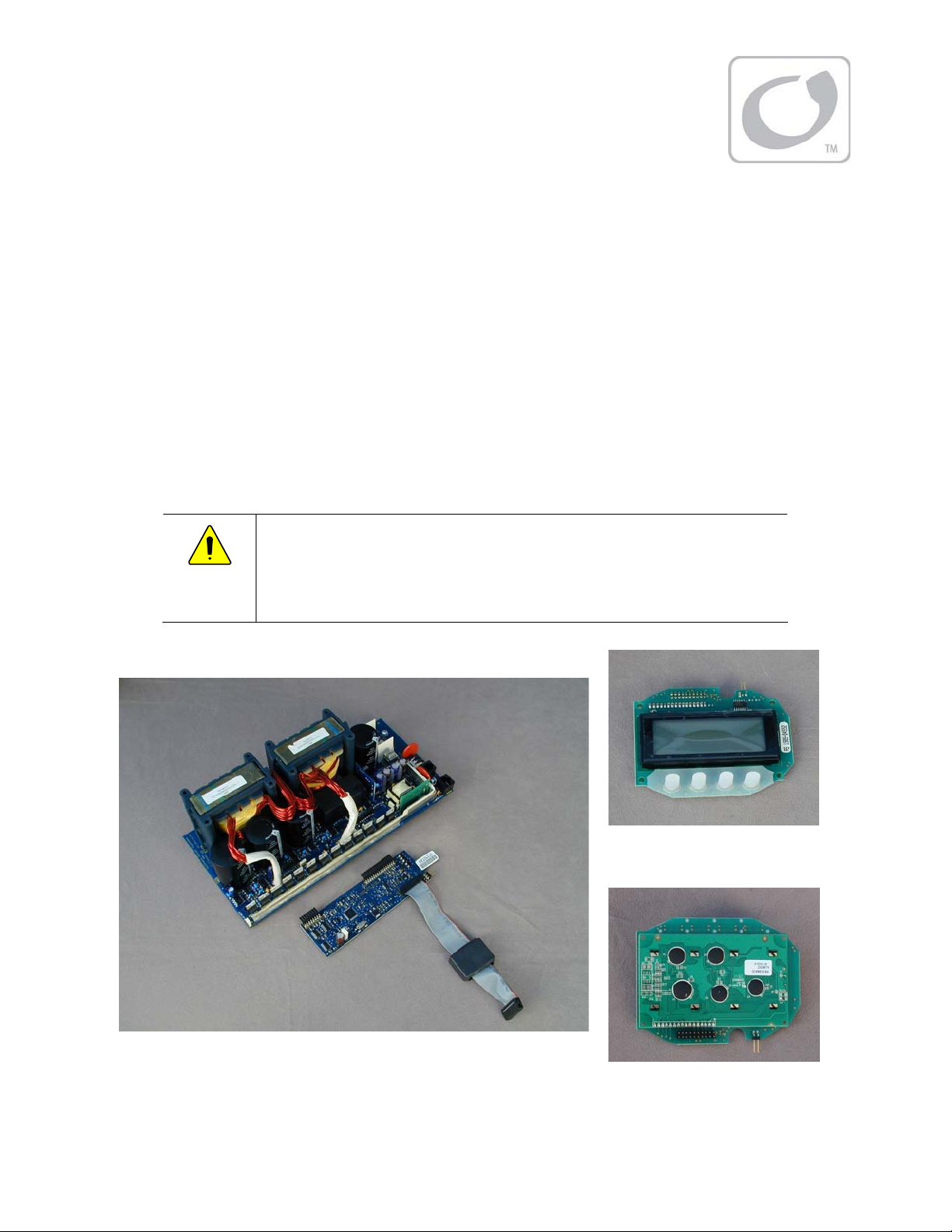
This step-by-step guide illustrates the replacement of the Control Board, Power Board and Button Board
for all FLEXmax Series Charge Controllers. It also illustrates t h e r ep lacement of t he Fan for FLEXmax 60
charg e cont rollers only. It does not cover replacing the f an in a FLEXmax 80 charge controller.
A static-safeguarded workspace should be used to preserve the FLEXmax controller’s static-sensitive
compon ent s during t he removal and i n st al l at ion procedure. See the sect ion t it led Equipment Safet y on
page 3 for more speci f ic i nstruct ions.
Please review this guide and familiarize yourself with the complete repair procedure. OutBack technical
support is also available at
CAUTION: Equ ip men t Dam ag e
This procedure involves sensitive electronics which must be handled gently
and carefully during removal and installation. Applying excess force can
damage the components and cause the FLEXmax controller to malfunction.
(360) 618-4363
or
support@outbackpower.com
.
But t on Boar d
(front )
Power Boar d
Cont rol Board
Power Boar d
(back)
Figure 1 Components
900-0054-01-00 Rev A 7
Page 10
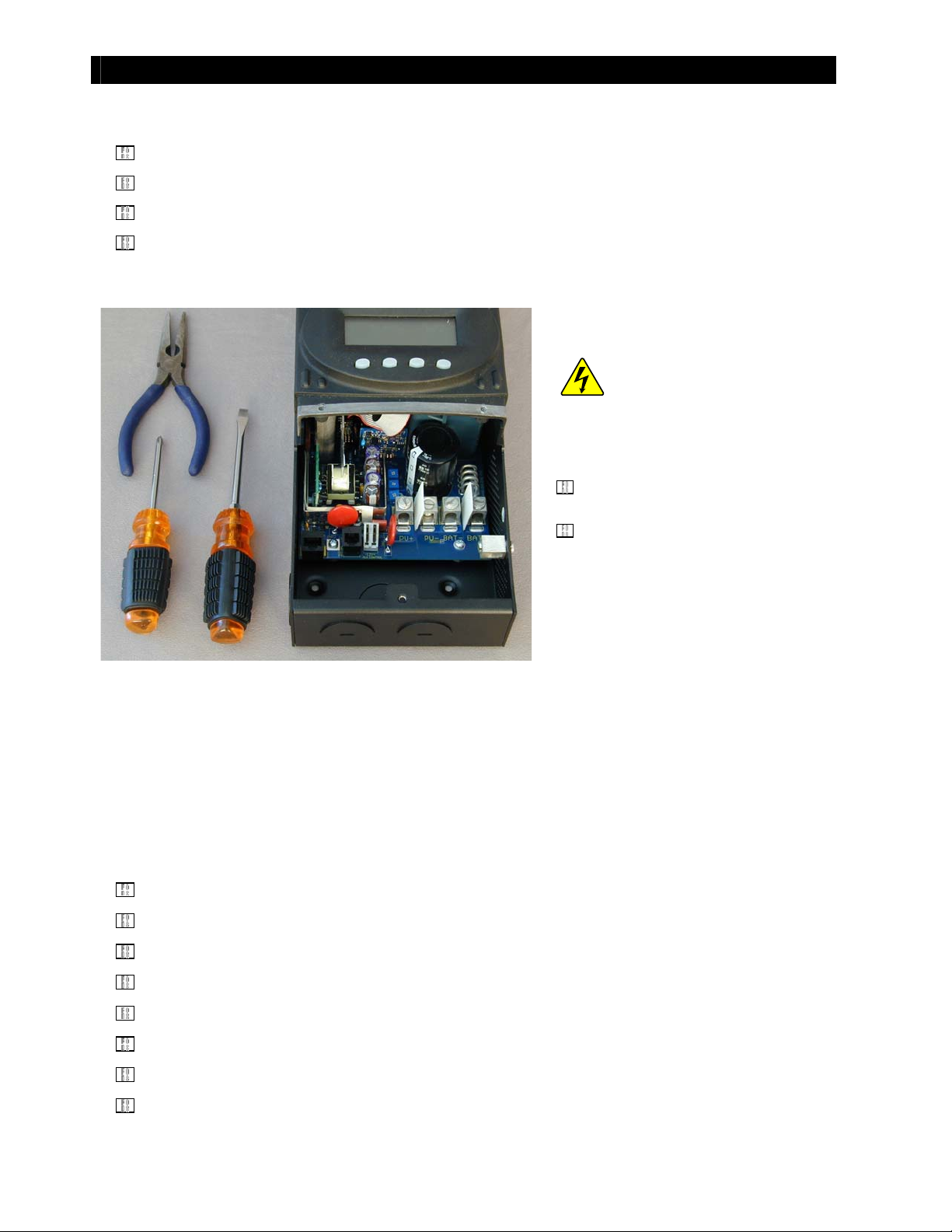
Tools Requi r ed
Phillips Screwdriver
Fl at Scr ew d r i ve r
Long-Nose Pli er s
Diagonal Wire Cutters (not shown)
Preliminary
Introduction
WARNING: Shock Hazar d
If the unit has been in use, power can
still be present even after the unit has
been disconnect ed.
Remove all electrical connections
fro m t he FLEXmax cont roller.
Allow the cont rol ler to “ rest” for
approximately ten minutes to fully
di scharge t he PV inp ut capacit ors.
Figure 2 Charge Controller “ At Rest”
: As many as 33 screws may be removed duri n g t his proced ure. Be sure to put them aside in t he
NOTE
order they are removed.
Summary List of Instructions
The following is a list of the instructions that are included in this document.
For instructions for
For instructions for
For instructions for
For instructions for
For instructions for
For instructions for
For instructions for
For instructions for
Removing the FLEXmax 80 Fan Cable
Di sassem b li ng t he Chassi s
Removing the Heat Sink
Rem ov in g t h e FET Bar
Sep ar at i ng t h e Heat Si nk f ro m t he Po wer Bo ar d
Replacing the Fan and Button Board
Replacing the Control Board and Power Board
Reassembling the Char ge Cont roller
, start on page 10.
, see page 11.
, see page 12
8 900-0054-01-00 Rev A
, see page 9.
, see page 14.
, see page 17.
, see page 23.
, see page 27.
Page 11

FLEXmax Charge Controller Disassembly
p
If you have a FLEXmax 60, proceed w i th removing t he chassis screws as described on page 10.
Removing the FLEXmax 80 Fan Cable
1. Remove t he machine screw t hat secures the
fan cover.
Pre ss
Pr es s
6. Not e the jack for t he fan
cable, whi ch is snapped
into t he f an bracket.
2. Press bot h sides of t he f an cover t o release t h e
tabs. Pull up on the cover.
3. Remove t he fan cover once t he t abs have
cleared t heir slot s. Keep t he fan cover and
machine screw in a safe place.
4. Note the fan cable plugged into the jack.
5.
Rem ove t he fan cable
by squeezing the tabs
on eit her side of t he
plug. You can do this
wit h your f i n gers, or
wit h a pair of longnose
liers.
Figure 3 Removing Fan Cover
7. Remove the cabl e jack by
pinching the retaining
tabs on eit her side of the
jack, using long-nose
pliers. The jack can b e
taken out through the
rear of t he bracket .
Figure 4 Removing Cable Jack
900-0054-01-00 Rev A 9
Page 12

Disassembly
Removing Chassis Screws
1. Set t he unit on it s side t o remove t he t wo back screw s. Keep t he screws and star washers toget her.
Fi gur e 5 Back Scr ew Rem oval
2. With the unit still on its side, remove two side screws.
Figure 6 Side Screw Removal (part 1)
3. Set the unit on its other side and remove the two remaining screws.
Figure 7 Side Screw Removal (part 2)
The heat sink can now be removed from the chassis.
10 900-0054-01-00 Rev A
Page 13

Removing the Heat Sink
Disassembly
1. To remove the heat sink, grip it along
each flank and raise its lower end.
2. Slide t he cont rol board past t he
grounding lug. Make certain the power
board is raised high enough to avoid
the grounding lug
Grounding lug
3. Sli de t he heat sink aw ay f r o m
the chassis.
Fi gur e 8 Heat Sin k Remo val
900-0054-01-00 Rev A 11
Page 14

Disassembly
Remo v i ng t h e FET Bar
1. Set the unit on its side as shown in Figure 9 and remove the 12 screws securing the FET mounting bar
t o t he heat sink.
Fi gu re 9 FET Bar Scr ew Remo val
2. Rem ove t he FET mount i ng bar.
Fi gur e 10 FET Bar Rem o val
Continued on next page.
12 900-0054-01-00 Rev A
Page 15

Fi gur e 11 Fr eei ng t he FET fr om t he In sul at or
Disassembly
3. Lif t t he t ab of t he FETs off
from the Sil-Pad (gray
insulator pad) using your
finger and t humb.
CAUTION! Do not at tempt
to remove the FETs from
the power board. The FET
pins are soldered t o t he
board.
If t he FETs are difficul t to
break free, rock the tabs
gently with long-nose pliers
until they lift off the Sil-Pad.
Fi gur e 12 Fr eei ng t h e FET w it h Pl i er s
900-0054-01-00 Rev A 13
Page 16

Disassembly
Sep ar at i n g t h e Heat Si n k f r om t he Pow er Bo ar d
Place t he charge cont roller upside down and rem ove t he seven screws circled i n whit e in Figure 13, on
t he l eft . Do not remove the f our cradle screw s and w ashers identified wi t h t he X symb ol in Fi g ur e 13 on
the right.
Do NOT Remove the screws
id ent ified here wit h an “X” .
Figure 13 Bottom/Cradle Screw Removal
2. Remove t he last t hree (3)
remaining screws, circled
in whit e i n Figure 14.
Figure 14 Removing Remaining Screws
Continued on next page.
14 900-0054-01-00 Rev A
Page 17

Disassembly
p
3. With all the screws
removed, t he heat sin k can
be separated from the
power board. Set t he unit
up right and carefully pry
and l ift th e heat sink off t he
ower board.
Figure 15 Heat Sink Removal
CA UT I ON !
removal. The heat sin k is
connected to the power board
by a ribbon cable f rom t he
cont rol board.
Do not force t he
Fi gu re 1 6 Heat Sin k Co n nect ed t o Po w er Bo ar d
Continued on next page.
900-0054-01-00 Rev A 15
Page 18

Fi gur e 17 Cab le Remo val
Disassembly
4. Set t he heat sink on it s sid e and t he
power board down flat.
5. Remove the ri bbon cable connect or
from t he LCD connect or.
The connector may have a dollop of
sil i cone sealant o n it which must be
peeled off. When reassembling t he
controller, it is recommended to apply
more silicone sealant if available.)
If you have a FLEXmax 60 controller and
are only replacing the fan, it is not
necessary t o remove t he cable.
Figure 18 Power Board - Top View
For instructions on
For instructions on
For instructions on
For instructions on
Rep l a ci ng t he Fan in a FLEXm ax 60 Char ge Con t ro ll er
Replacing the Button Board
Replacing the Control Board and Power Board
Reassembling the Controller
, see page 17.
, see page 19
, see page 24.
, see page 27.
16 900-0054-01-00 Rev A
Page 19

Fan an d But t on Boar d
Replacing the FLEXmax 60 Fan
Disassemble the controller as described on page 9 through page 16.
Remo v i ng t h e Fan
To remove t he fan:
Disconnect the connector from the LCD. The
1.
Silicone Sealant
connector may have a dollop of silicone sealant to
ensure a firm connection. This should be peeled or
pulled off.
Rem ove t he four screw s holding the f an in place.
2.
The ribbon cable is shown d i sconnect ed
NOTE:
in this illustration for convenience only.
Fan Screw s (x 4)
Fan Connector
Fi gur e 19 Fan Rem ov al
Rep l aci n g t h e Fan
Scr e w Po st
Black Wire
Re d Wi r e
Scr e w Po st
Fi gur e 20 Fan Rep lacem ent
Silicone Sealant
To rep l a ce t h e f an :
1. Insert the new fan aligning the mounting holes to
the heat sink.
2. Al i g n t he connect or so t hat th e red w ire of t he
connector lines up wit h the posit ive (+) pin and the
black w i re wit h t h e neg at ive (-) pin as show n i n
Figure 20. Posit ion the wires bet ween the
scr ew p ost s.
3. Plug in the connector.
4. Tight en t he screw s so t h e f an is snug against t he
heat sink.
5. Reapply silicone sealant to secure the connector
(if possible).
If no other repairs are necessary, see the reassembly instructions on page 27. After reassembly, return to
page 18 for testing procedures.
900-0054-01-00 Rev A 17
Page 20

p
Fan Test Pr ocedures
Test t he fan using t he following procedures:.
1. Remove t he Remot e Temperature
Sensor (RTS) jack f rom the p ort , if
present .
2. Insert a flat screwdriver insid e t he RTS
port. Gently press the screwdriver tip
against all the pins at once. This will
creat e a f al se signal t hat w ill t urn the
fan on.
Fan and Button Board
3. Check t h e LCD. The op erat ional mod e on
the FLEXmax screen should change from
“Sleeping” t o “BatTmpErr” . The fan will
begin running.
4. Once t he fan operat i on has been verified,
remove t he screw driver fro m t he RTS p o rt
and reconnect the RTS, if available.
RTS Po r t
LCD Display
IN 005 V OUT 25.0 V
00.0 A 00.0 A
Watts 0000 AuxOff
kWHrs 00.0 BatTm
Figure 21 Fan Test Procedure
You may now apply PV input to the FLEXmax Charge Controller to resume charging.
Err
18 900-0054-01-00 Rev A
Page 21

Replacing the Button Board
To locate the but t on board:
1. Disassemble the controller as described
on page 11 through page 18.
2. Remove t he Remote Temperature Sensor
(RTS) fro m t he port, if p r esent .
3. The Button Board is located on the inside
of the heat sink.
Fan and Button Board
Figure 22 Locating the Button Board
Fan Connector
But t on Boar d
Silicone Sealant
Fan Connector
To disconnect the fan:
1.
Disconnect the fan by gently pulling the
connector away from the butt on board..
Remove the Silicone Sealant if present.
2.
But t on Boar d
Figure 23 Disconnecting the Fan
900-0054-01-00 Rev A 19
Page 22

Fan and Button Board
The but t on board is mounted t o t he
heat sink on four met al peg s at t he
corn er s of t he b oard. It is retained in
place by push-nuts which slide over
each peg, and which are covered in
t urn by silicone sealant.
To ex p ose t he pegs:
1. Remove the silicone sealant from
all f our pegs.
Figure 24 Exposing the Button Board Mounting Peg
Figure 25 Gripping the Push-nut
Once the push-nuts are exposed,
t hey will need t o be removed wit hout
damaging the metal pegs. The pushnut is very t hin and does not have
much o f an edge. Using a sharp set
of wire cut ters, remove the push-nut s
by squeezing t hem on eit her side so
that they deform.
To remove the push-nut :
1. Carefully grip the push-nut on
either side with the wire cutters.
Be sure not to damage t he peg or
Continued on next page.
20 900-0054-01-00 Rev A
Page 23

Fi gu re 26 Def or mi ng t he Pu sh-n u t
Fan and Button Board
2. Slowly close the wire cutt ers, exerting
enough pressure to crush or deform
the push-nut. The push-nut cannot be
reused aft er doi ng t hi s.
Figure 27 Removing Push-nut
3. Once t he push-nut is deformed,
push t he wi re cut ters beneat h it
and p r y it off t he peg .
4. Fin all y, work t he but ton board free of
t he f our pegs and remove it f rom t he
housing.
Figure 28 Removing the Button Board
Continued on next page.
900-0054-01-00 Rev A 21
Page 24

Fan and Button Board
Figure 29 Inserting the New Button Board
5. Insert t he repl acement board and ali gn
it w i th the f our pegs.
6. Lay a repl acement push-nut over each peg.
The push-nuts are not flat. Make certain to
place t hem so t hat t he edges are lower and
the convex cent er is higher.
7. Using t he wire cut ters or long-nose pliers,
press along both sides of the push-nut so
that it is driven onto the peg. Continue
pressing until the push-nut is firmly against
t he b u t ton b oard.
8. Repeat w i th the ot her t hree push-nuts
and pegs.
Figure 30 Inserting New Push-nut
9. Reattach the connector for t he fan.
10. If possible, reapply silicone sealant to
secure t he fan connect or and t he four
push-nuts.
Pro ceed t o t h e n ext sect i on if you n eed t o
replace t he cont rol board or power board.
If not , p roceed to page 27 to begin
reassembling the charge controller.
Fi gu re 3 1 Reco nn ect i ng t he Fan
22 900-0054-01-00 Rev A
Page 25

Control Board and Power Board
p
Removing the Control Board
Cont rol Board
Do NOT r ai se t he se
inductor wires
1. Raise t he one set of i nduct or wires that
passes over t he cont rol board, to all ow
room for t he control board to move.
Do no t raise the ot her set of wires.
Raise t hese in duct or wir es
Figure 32 Lifting the Inductor Wires
Figure 33 Sliding the Control Board Out
2. Pinch t he ends of t he cont rol board and
pull upward.
3. If t he b oard resist s, gr adu all y p ul l u p o ne
end at a t ime, alt ernat i ng b et ween t he
two ends.
4. Remove the control board by sliding it out
of the power board, avoidi ng any
component s on the board.
The pins of t he cont rol board
CA UTI ON !
should not be obstructed by the components
on the
ower board.
900-0054-01-00 Rev A 23
Page 26

Control Board and Power Board
Replacing the Control Board or Power Board
1. Inspect the connector pins on the
control board for any bends.
St raight en any bent p i ns wi th a flat
screwdriver or your finger.
Figure 34 Bent Pin on Control Board
2. Slide t he cont rol board i nt o t he power
board. Do not hit any components on the
power board.
Figure 35 Inserting Control Board
3. Inspect the pins again before connecting
t he co nt rol board t o t h e p ower board .
4. Carefully align the control board connector
wit h t he power board connect or. Be sur e
t he p in s an d h ol es ar e l i ned up w it h each
other precisely.
5. When the pins and connectors line up,
push t he cont rol board i nt o t h e
power board.
Pi ns
Connector Holes
Continued on next page.
Figure 36 Pins and Connectors
24 900-0054-01-00 Rev A
Page 27

Control Board and Power Board
Scr e w Ho l e on
the Heat Sink
FET
Sil-Pad
Fi gu re 3 7 FETs an d Si l- Pad In sul at or on Heat Si nk
6. Using t he replacement t hat came wit h
t he new b oard, rep lace t he gray Sil-Pad
insulator on the heat sink.
IM PORTANT:
Make cert ai n t he new Sil-Pad i s lined up wit h t he screw hol es on the heat sink.
CAUTION: Equ i p men t Fai l ur e
Always replace t he Sil-Pad even if t he old Sil -Pad appears usable. It could easily
have been damaged when removing the heat sink from the power board. Even
a pin-sized hol e can lead t o cat astrophic board f ai l u re.
900-0054-01-00 Rev A 25
Page 28

Notes:
Control Board and Power Board
26 900-0054-01-00 Rev A
Page 29

Reseating the Control or Power Board
Reassembl y
1. Push on both ends of the
control board to confirm
it is still properly seated
on the power board.
Figure 38 Reseating Control Board
Figure 39 Placing Inductor Wires
2. Bend and move the
inductor wires over the
control board . These are
the same inductor wires
which were bent out of
the way in Figure 32.
Make sure the wires do
not strike the fan or
button board when the
heat sink is reinstalled.
900-0054-01-00 Rev A 27
Page 30

Reconnecting the Heat Sink to the Power Board
1. Wit h t he cont rol board secured t o t he
power board, connect the ribbon cable.
Reassemb ly
Fi gu re 4 0 Rei nst al l in g Ri bb on Cab le
CA UT I ON !
Do no t install it backward. In the correct
or i en t ation , t he red stripe must face t he
heat sink side wall.
In Figure 40, the cab l e is orient ed so t h at
t he red st ri p e i s on t he bot t om.
2. Set and align t he heat sink ont o t he
power board.
3. While aligning t he h eat sin k, t uck one
finger under the ribbon cable and pull
as indicat ed i n Figure 41. This wi l l take
up the slack in t h e ri b b on cable. It
keeps the cable from int erfering with
t he al i g nment of t h e h eat sink and t he
power board.
The ribbon cable i s not keyed.
Figure 41 Gently Pulling On Ribbon Cable
4. Set t he unit upside dow n, and align
the power board screw holes against
the heat sink screw holes.
5. Reinstall al l the screws that had been
removed previously and handtighten them.
Continued on next page.
Figure 42 Installing and Tightening Screws
28 900-0054-01-00 Rev A
Page 31

6. Set t he unit on it s sid e wit h t he FETs in
7. If you are reassembling the unit
Fi gu re 4 3 Al i gn i ng FETs an d I nst al l in g t h e FET Bar
Reassemb ly
between the screw holes on the
heat sink.
If t hey do no t line up, move the t abs on
the FETs to align them bet ween t he
screw holes. The alignment of the FETs
between the screw holes protects them
from damage when reinstalling the FET
mounting bar and screws.
(following fan replacement) and have
not already p erf ormed t hi s step: using
the replacement that came with the fan,
replace the gray Sil-Pad insulator on the
heat sink. Refer to t he illustration on
page 27 i f n ecessary.
CAUTION: Equ i p men t Dam ag e
Always replace t he Sil -Pad even i f t he old Sil-Pad appears usable. It
could easil y have b een damaged w hen removi n g t he heat sink f rom the
power b oard. Even a p in -sized h o l e can lead to cat astrophic board
failure.
Make sure t he new Sil-Pad i s lined up wit h t he screw holes on t he
heat sink.
8. Place the FET mounting bar on
the FETs.
9. Install the FET bar screws and
tighten.
Figure 44 Installing FET Bar Screws
900-0054-01-00 Rev A 29
Page 32

Reconnecting the Heat Sink to the Chassis
1. Slide the reassembled unit into
the chassis working around the
Grounding lug.
Grounding lug
Figure 45 Reinstalling the Heat Sink onto the Chassis
Reassemb ly
3. Replace and tighten down
scr ew s o n t h e si d es o f t he ch assi s.
all
t he
Fig ur e 46 Repl aci ng t he Chassi s Screws
2. Replace and tighten down
screws on t he back of t he chassis.
all
t he
30 900-0054-01-00 Rev A
Page 33

Reassemb ly
For the FLEXmax 80 Controller, follow the st eps on for reinstalling t he fan plug bef ore proceedi ng.
Reinstalling FLEXmax 80 Fan Plug
1. Sn ap t he fan cable j ack int o t he
bracket.
Figure 47 Reinstalling Cable Jack
Fi gu re 4 8 Rei nst al l in g Cab l e Pl ug
2. Sn ap t he fan cable i nt o t he j ack.
3. Replace the FLEXmax 80 fan cover.
Fi gur e 49 Fan Cover
900-0054-01-00 Rev A 31
Page 34

Reassemb ly
Syst em Fun ct i onal Test
Perform a Funct ional Test as fol l ows before putt ing t h e syst em back into full service.
1.
Rei n st al l FLEXmax Charge Cont roller b ack int o t he system.
Initially apply only battery power to the FLEXmax controller.
2.
3.
The display should “boot up” and the soft keys should function properly. Test t he soft keys by
cycling through the menus.
Once proper operation is verified, apply PV input to the FLEXmax Charge Controller to
4.
resume charging.
5.
Using a digital multimeter, test the applicable test points to confirm prop er volt age levels as they
are applied to the system.
6.
Replace all t h e app rop r i ate co m p onent covers and secure t he system for official use by the
customer.
If t he unit does not perform as expect ed or fails the Funct ional Test , di sco nn ect al l p ow er so urces
(i.e. open all breaker s or d i scon nects) and contact Out Back Technical Support f or addit ional assistance.
32 900-0054-01-00 Rev A
Page 35

Notes:
Reassemb ly
900-0054-01-00 Rev A 33
Page 36

Nort h Am erica
19009 62nd Avenue NE
Arlington, WA USA
+1.360.435.6030
900-0054-01-00 Rev A
European Office:
Bar cel o n a, Esp añ a
+34.93.654.9568
 Loading...