

OutBack Power EnergyCell 2200RE, EnergyCell 1100RE, EnergyCell 2000RE, EnergyCell 2700RE, EnergyCell 1300RE Installation Manual And Owner's Manual
...
EnergyCell® RE High Capacity Battery
Installation Guide and Owner’s Manual
Purpose
This document provides the EnergyCell RE High Capacity Installation Guide and Operation Manual.
Scope
This document applies to all models of the EnergyCell RE High Capacity series. The reference table below shows the Outback part
number cross referenced with the manufacturer part number. When using this document for installation and service operations,
please refer to the manufacturer part number when referencing critical information.
Should you have ANY questions concerning how to perform the required maintenance or installation please contact Outback
Power at the oce number listed below and ask for Outback Power Tech Support.
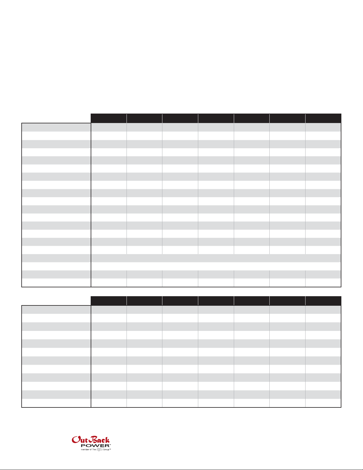
EnergyCell RE High Capacity Specications
Models: 800RE 1100RE 1300RE 1600RE 2000RE 2200RE 2700RE
EnerSys Part Number
Nominal Voltage Per Cell
Capacity 20Hr Rate (1.75VPC)
Capacity 100Hr Rate (1.75VPC)
Watts Per Cell 15min Rate (1.67VPC)
Cycle Life 50% DOD (25°C)
Optimal Operating Temperature Range
OCV Per Cell Limit
Initial Charge Voltage Per Cell
Float Voltage Per Cell (25°C)
Float Voltage Per Cell (35°C)
Equalize Voltage Per Cell (21 to 32°C)
Maximum Charge Current (A)
Shelf Life (25°C)
Short Circuit Current (A)
Internal Resistance (micro Ω)
Terminal Torque (Intercell Connects)
Hardware Specication (Intercell Connects)
Weight Per Cell (lbs)
Dimensions Per Cell L x W x H (in)
Models: 800RE 1100RE 1300RE 1600RE 2000RE 2200RE 2700RE
1 hour
2 hours
3 hours
4 hours
5 hours
6 hours
8 hours
10 hours
12 hours
20 hours
24 hours
100 hours
DDm85-15 DDm85-21 DDm100-21 DDm100-25 DDm125-25 DDm100-33 DDm125-33
2V 2V 2V 2V 2V 2V 2V
672 960 1148 1378 1716 1836 2288
810 1150 1340 1600 2070 2140 2770
1230 1757 1995 2394 3071 3192 4094
1800 cycles 1800 cycles 1800 cycles 1800 cycles 1800 cycles 1800 cycles 1800 cycles
23 to 26°C 23 to 26°C 23 to 26°C 23 to 26°C 23 to 26°C 23 to 26°C 23 to 26°C
*
2.05 2.05 2.05 2.05 2.05 2.05 2.05
**
2.27 2.27 2.27 2.27 2.27 2.27 2.27
2.25 2.25 2.25 2.25 2.25 2.25 2.25
2.21 2.21 2.21 2.21 2.21 2.21 2.21
2.32 2.32 2.32 2.32 2.32 2.32 2.32
148.75 212.5 250 300 375 400 500
6 months 6 months 6 months 6 months 6 months 6 months 6 months
4728 6748 7722 9267 12411 12337 16548
441 309 270 225 167 169 126
88 in-lbs
M8 bolt, lock and at washer
114.3 162.3 188.3 222.3 272.3 290.3 358.3
21.8 x 11.9 x 6.5
21.8 x 8.4 x 6.5 24.5 x 8.4 x 6.5 24.5 x 9.9 x 6.5 23.5 x 9.9 x 8.9 24.5 x 12.9 x 6.5 23.5 x 12.9 x 8.9
Ah Capacity to 1.75VPC @ 25°C
347 495 575 690 886 920 1182
440 631 738 884 1138 1180 1518
492 702 822 987 1260 1317 1680
528 752 876 1052 1332 1404 1776
555 790 920 1105 1390 1470 1850
576 822 954 1146 1440 1524 1914
600 864 1008 1208 1512 1616 2016
610 870 1040 1250 1550 1660 2060
624 888 1068 1284 1584 1704 2112
672 960 1148 1378 1716 1836 2288
676 984 1176 1416 1776 1872 2352
810 1150 1340 1600 2070 2140 2770
The following PowerSafe DDM Modular Battery Systems Installation Manual is copyright 2003 by EnerSys. This document cannot
be copied or reproduced without the express written permission of EnerSys Inc.
Worldwide Corporate Oces
North America
Tel: +1 360.435.6030
Fax: +1 360.435.6019
Latin America
Tel: +1 561.792.9651
Fax: +1 561.792.7157
Europe
Tel: +49 9122.79889.0
Fax: +49 9122.79889.21
Asia Pacic
Tel: +852 2736.8663
Fax: +852 2199.7988

Installation Manual
PowerSafe DDM
Modular Battery Systems
DDm
Publication No. US-DDm-IM-003 November 2003

DDm
Installation Manual
PowerSafe DDm
Modular Battery Systems
IMPORTANT!
Read safety information first
See Safety, Storage, Operating and Maintenance Manual
Publication No. US-DDm-IM-003 November 2003

The installation manual is for reference only. To maximize safety and performance, read the
accompanying Safety, Storage, Operating and Maintenance Manual thoroughly. It provides full
instructions regarding safety, storage, operation and maintenance. Failure to observe the
precautions as presented may result in injury or loss of life.
Copyright ©2003 by EnerSys Inc. All rights reserved.
This document is proprietary to EnerSys Inc. This document cannot be copied or reproduced in
whole or in part, nor can its contents be revealed in any manner or to any person except to meet
the purpose for which it was delivered, without the express written permission of EnerSys Inc.
Please check our website for literature updates.
www.enersysinc.com
Publication No. US-DDm-IM-003
November 2003 www.enersysinc.com
PowerSafe DDm
GENERAL SAFETY INSTRUCTIONS
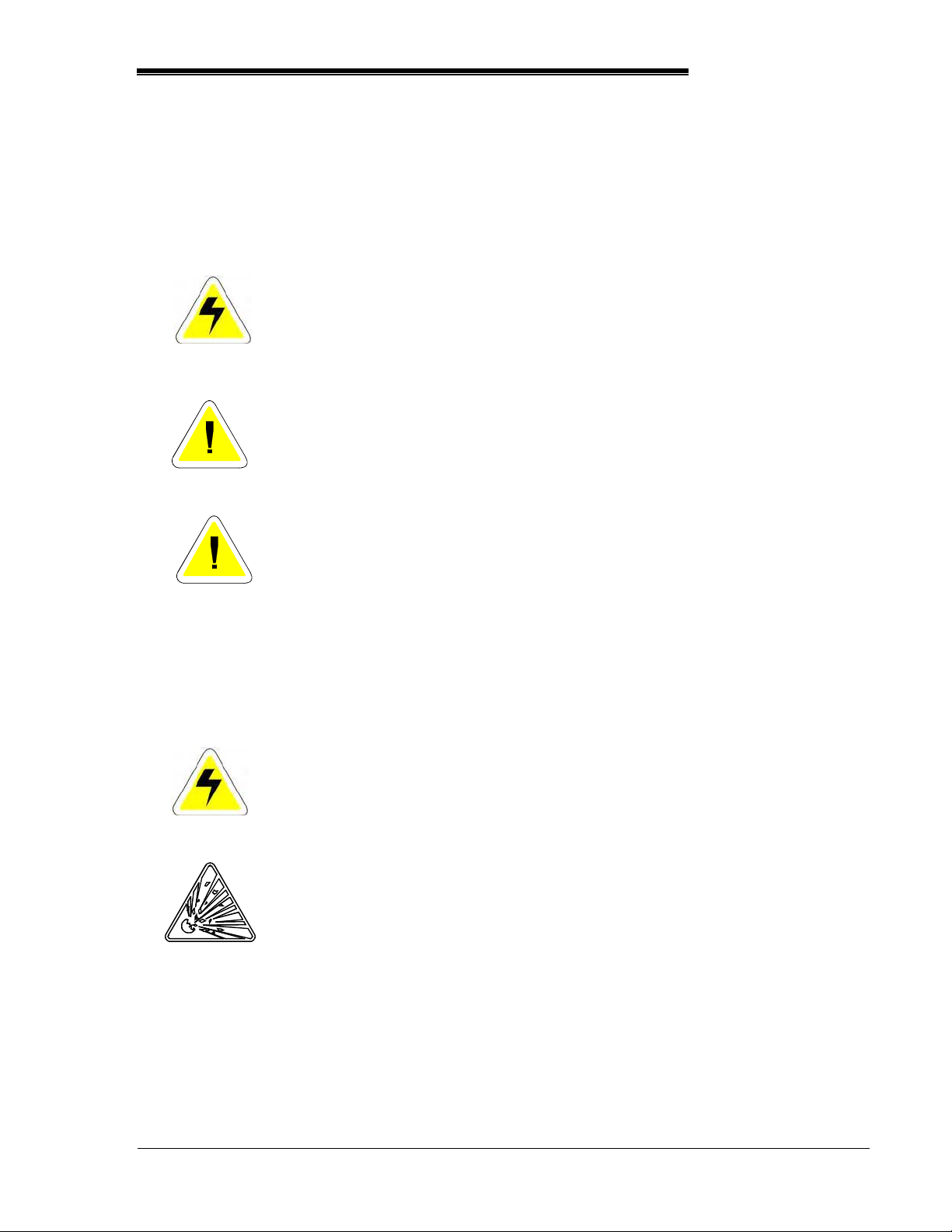
Warnings in this manual appear in any of three ways:
Danger
Warning
Caution
Other warning symbols may appear along with the Danger and Caution symbol and are used to
specify special hazards. These warnings describe particular areas where special care and/or
procedures are required in order to prevent serious injury and possible death:
Electrical
warnings
Explosion
warnings
The danger symbol is a lightning bolt mark enclosed in
a triangle. The danger symbol is used to indicate
imminently hazardous situations, locations and
conditions which, if not avoided, WILL result in death,
serious injury and/or severe property damage.
The warning symbol is an exclamation mark in a
triangle. The warning symbol is used to indicate
potentially hazardous situations and conditions, which,
if not avoided COULD result in serious injury or death.
Severe property damage COULD also occur.
The caution symbol is an exclamation mark enclosed
in a triangle. The caution symbol is used to indicate
potentially hazardous situations and conditions, which,
if not avoided may result in injury. Equipment damage
may also occur.
The electrical warning symbol is a lightning bolt mark
enclosed in a triangle. The electrical warning symbol is
used to indicate high voltage locations and conditions,
which may cause serious injury or death if the proper
precautions are not observed.
The explosion warning symbol is an explosion mark
enclosed in a triangle. The explosion warning symbol is
used to indicate locations and conditions where
molten, exploding parts may cause serious injury or
death if the proper precautions are not observed.
Publication No. US-DDm-IM-003 Page i
November 2003 www.enersysinc.com

IMPORTANT SAFETY INSTRUCTIONS
A battery can present a risk of electrical shock and high short circuit current.
The following precautions should be observed when working with batteries.
1. Verify that the Uninterruptible Power Supply (UPS) is off and that the power cord is
disconnected from the power source.
2. Remove watches, rings or other metal objects.
3. Use tools with insulated handles to prevent inadvertent shorts.
4. Wear rubber gloves and boots.
5. Do not lay tools or metal parts on top of batteries.
6. Determine if the battery is inadvertently grounded. If inadvertently grounded, remove
source of ground. Contact with any part of a grounded battery can result in electrical
shock. The likelihood of such shock will be reduced if such grounds are removed during
installation and maintenance.
7. Verify circuit polarities before making connections.
8. Disconnect charging source and load before connecting or disconnecting terminals.
9. Valve-regulated lead-acid (VRLA) batteries contain an explosive mixture of hydrogen
gas. Do not smoke, cause a flame or spark in the immediate area of the batteries. This
includes static electricity from the body.
10. Use proper lifting means when moving batteries and wear all appropriate safety clothing
and equipment.
11. Do not dispose of lead acid batteries except through channels in accordance with local,
state and federal regulations.
Page ii Publication No. US-DDm-IM-003
www.enersysinc.com November 2003
PowerSafe DDm
IMPORTANT SAFETY INSTRUCTIONS
SAVE THESE INSTRUCTIONS
This manual contains important instructions for PowerSafe DDm Lead-Acid Battery Systems
that should be followed during the installation and maintenance of the battery system.
Only a qualified EnerSys Inc. service representative who is knowledgeable in batteries and
the required precautions should perform servicing of the batteries. Keep unauthorized
personnel away from batteries.
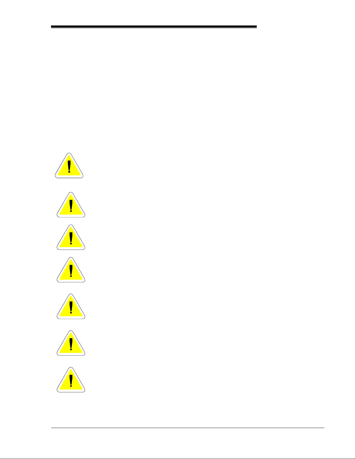
Caution
Caution
Caution
Warning
Warning
Warning
Warning
Misuse of this equipment could result in human injury and
equipment damage. In no event will EnerSys be responsible or
liable for either indirect or consequential damage or injury that may
result from the use of this equipment.
Do not dispose of the batteries in a fire. The batteries may
explode.
Do not open or mutilate the batteries. Released electrolyte is
harmful to the eyes and skin and may also be toxic.
This unit contains sealed lead acid batteries. Lack of preventative
maintenance could result in batteries exploding and emitting
gasses and/or flame. An authorized, trained technician must
perform annual preventative maintenance.
Failure to replace a battery before it becomes exhausted may
cause the case to crack, possibly releasing electrolyte from inside
the battery and resulting in secondary faults such as odor, smoke
and fire.
Installation and servicing of batteries should be performed by
personnel knowledgeable about batteries and the required
precautions. Keep unauthorized personnel away from the
batteries.
Proper maintenance to the battery system of this unit must be done
by a qualified service technician. This is essential to the safety and
reliability of your Uninterruptible Power Supply (UPS) system.
Publication No. US-DDm-IM-003 Page iii
November 2003 www.enersysinc.com

IMPORTANT!
Read safety information first
See Safety, Storage, Operating and Maintenance Manual
Page iv Publication No. US-DDm-IM-003
www.enersysinc.com November 2003

PowerSafe DDm
TABLE OF CONTENTS
GENERAL SAFETY INSTRUCTIONS ...........................................................................................i
GENERAL INFORMATION...........................................................................................................2
RECOMMENDED INSTALLATION EQUIPMENT AND SUPPLIES .............................................4
SYSTEM LAYOUT ........................................................................................................................5
Anchor Spacing .........................................................................................................................6
FRAME ASSEMBLY AND INSTALLATION ..................................................................................7
Base Beams ..............................................................................................................................7
Vertical Channels ......................................................................................................................7
Horizontal Channels ..................................................................................................................8
Cell Support Shelves ...............................................................................................................10
BATTERY CELL INSTALLATION ...............................................................................................11
Module Retainers ....................................................................................................................12
Electrical Bonding Instructions ................................................................................................12
CONNECTIONS..........................................................................................................................13
Terminal Plates........................................................................................................................13
Inter-Cell Connectors...............................................................................................................14
Terminal Bars ..........................................................................................................................15
INITIAL SYSTEM READINGS ....................................................................................................16
SAFETY SHIELDS AND COVERS .............................................................................................17
Safety Shields..........................................................................................................................17
Terminal Plate Covers .............................................................................................................17
Publication No. US-DDm-IM-003
November 2003 www.enersysinc.com
GENERAL INFORMATION
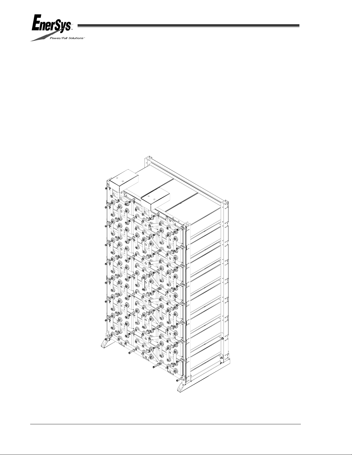
PowerSafe DDm battery systems are modular units that can be installed in a SINGLE STACK
(figure 1), a MULTI-STACK (figure 2), or a MULTI-STACK ZERO SEPARATION (Figure 3).
Systems are available in 24, 48 and other voltage configurations. These systems allow for
assembly at remote locations.
See the ASSEMBLY DRAWING to determine the configuration for your installation.
Before installation: Verify items received versus Bill of Lading. Verify parts against system Bill
of Materials.
SINGLE STACK
FIGURE 1
Page 2 Publication No. US-DDm-IM-003
www.enersysinc.com November 2003

MULTI-STACK
FIGURE 2
PowerSafe DDm
MULTI-STACK ZERO SEPARATION
FIGURE 3
Publication No. US-DDm-IM-003 Page 3
November 2003 www.enersysinc.com

RECOMMENDED INSTALLATION EQUIPMENT AND SUPPLIES
Before working with the battery system, be sure that you have the proper protective clothing,
safety equipment and insulated tools as specified in the Safety, Storage, Operating and
Maintenance Manual for the VRLA Modular Battery Systems.
The following is a recommended list of equipment required for installation of a PowerSafe DDm
Battery System.
TABLE 1
EQUIPMENT REQUIRED
CHECK IF ON HAND
Chalk Line
Torpedo Level (Plastic)
Torque Wrench (10-200 in-lbs) (SAE & Metric)
Torque Wrench (50-100 ft-lbs) (SAE & Metric)
Floor Anchors (User-supplied per battery system)
Floor Shims (User-supplied)
Drive Ratchet Wrench with Minimum 3” Extension (SAE & Metric)
Box Wrenches (SAE & Metric)
Screwdrivers
Wipes, Paper or Cloth
Stiff Bristle Nonmetallic Brush/Pad
Tape Measure (Nonmetallic)
Safety Equipment and Clothing
Small Paintbrush
Standard Allen Wrench Set
Be sure you have all the proper protective clothing, safety tools, and
equipment on hand before starting the installation.
Page 4 Publication No. US-DDm-IM-003
www.enersysinc.com November 2003

SYSTEM LAYOUT
Before installing the battery system, lay out
available floor space including aisles for
installation, maintenance and possible cell
replacement. Consult the local installation
considerations as determined in Section 5 of
the Safety, Storage, Operating and
Maintenance Manual for the VRLA Modular
Battery Systems. Recommended clearance
between these racks and any objects (including
walls and equipment) is 4 inches (102 mm).
1. Layout the system position for either a
SINGLE-STACK (Figure 4), a MULTISTACK (Figure 5), or MULTI-STACK WITH
ZERO SEPARATION (Figures 6, 7 & 8)
configuration with the dimensions defined in
Table 2.
2. Locate the position of the floor anchors
using the frame base beams.
NOTE:
• Floor anchoring is REQUIRED for all
installations.
• Allow sufficient clearance between
adjacent walls or equipment for
proper installation of anchors. Please
check your local codes for clearances
required.
• Floor anchor design (including, but
not limited to size, quantity, and
capacity) and installation are the
responsibility of the user/installer.
• Follow the user’s design and the
manufacturer’s instructions.
3. Mark floor with the position of the floor
anchors.
L
D
D = DISTANCE BETWEEN BASES (VARIABLE)
MULTI-STACK
FIGURE 5
M
M
DDm50 MULTI-STACK
WITH ZERO SEPARATION
FIGURE 6
M
7.67
DDm85/100 MULTI-STACK
WITH ZERO SEPARATION
FIGURE 7
PowerSafe DDm
L
FRONT
FRONT
W
M
FRONT
W=
DDm85 = 17.46
DDm100 = 20.47
SINGLE-STACK
FIGURE 4
“L”
FRONT
M
10.75
M
Dm125 MULTI-STACK
WITH ZERO SEPARATION
19.81
FRONT
FIGURE 8
Publication No. US-DDm-IM-003 Page 5
November 2003 www.enersysinc.com
Anchor Spacing
TABLE 2
Base Beam Anchor Spacing
Cell
Model
L (in) L (cm) L (in) L (cm) L (in) L (cm) L (in) L (cm) M (in) M (cm)
50-09 9.04 23.0 N/A N/A 16.52 42.0 24.01 61.0 L+0.89 L+2.3
50-13 12.04 30.6 N/A N/A 22.52 57.2 33.01 83.8 L+0.89 L+2.3
50-17 15.49 39.3 22.48 57.1 29.26 74.3 43.17 109.7 L+0.89 L+2.3
85-13 12.04 30.6 N/A N/A 22.52 57.2 33.01 83.8 L-2.94 L-7.5
85-15 13.54 34.4 N/A N/A 25.52 64.8 37.51 95.3 L-2.94 L-7.5
85-21 18.48 46.9 26.93 68.4 35.26 89.6 53.71 136.4 L-2.94 L-7.5
85-25 21.48 54.6 31.43 79.8 41.26 104.8 62.68 159.2 L-2.94 L-7.5
85-27 22.98 58.4 33.69 85.6 44.27 112.4 67.22 170.7 L-2.94 L-7.5
85-33 27.48 69.8 40.43 102.7 53.26 135.3 80.71 205.0 L-2.94 L-7.5
100-21 18.48 46.9 26.93 68.4 35.26 89.6 53.71 136.4 L-2.94 L-7.5
100-25 21.48 54.6 31.43 79.8 41.26 104.8 62.68 159.2 L-2.94 L-7.5
100-27 22.98 58.4 33.69 85.6 44.27 112.4 67.22 170.7 L-2.94 L-7.5
100-33 27.48 69.8 40.43 102.7 53.26 135.3 80.71 205.0 L-2.94 L-7.5
125-25 22.09 56.1 31.88 81.0 41.98 106.6 63.29 160.8 L-4.24 L-10.8
125-27 23.59 59.9 34.14 86.7 44.98 114.2 67.83 172.3 L-4.24 L-10.8
125-33 28.09 71.3 40.88 103.8 53.98 137.1 81.32 206.6 L-4.24 L-10.8
2 Cells Wide 3 Cells Wide 4 Cells Wide 6 Cells Wide
Multi-Stack w/
zero spacing
EXAMPLE:
If you are installing a DDm85 MULTI-STACK WITH ZERO SEPARATION and
you have 21 plates/cell, 4 cells wide.
M (inches) = L (in) - 2.94”
35.26” - 2.94” = 32.32”
M (cm) = L (cm) - 7.5 cm
89.6 cm - 7.5 cm = 82.1 cm
Page 6 Publication No. US-DDm-IM-003
www.enersysinc.com November 2003
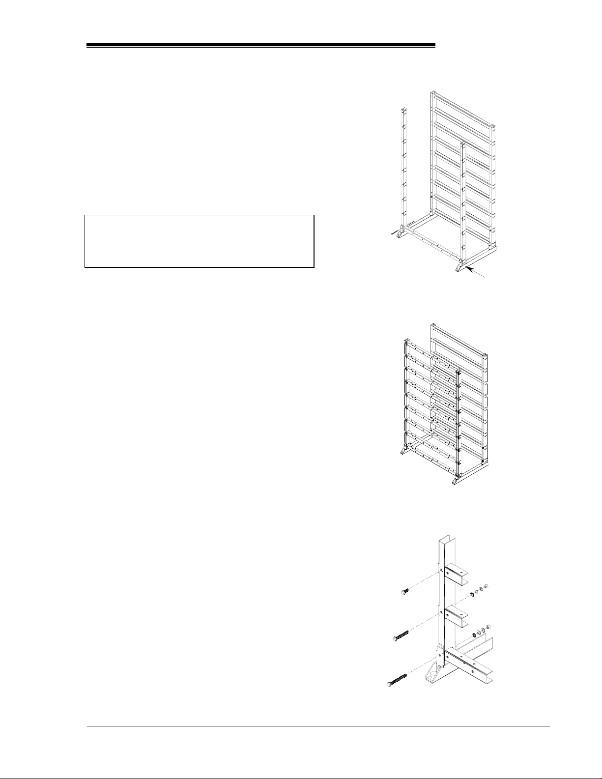
FRAME ASSEMBLY AND INSTALLATION
To assemble and install the frame for the
PowerSafe DDm battery system, follow the
procedure below using the system layout
determined in the “System Layout” section.
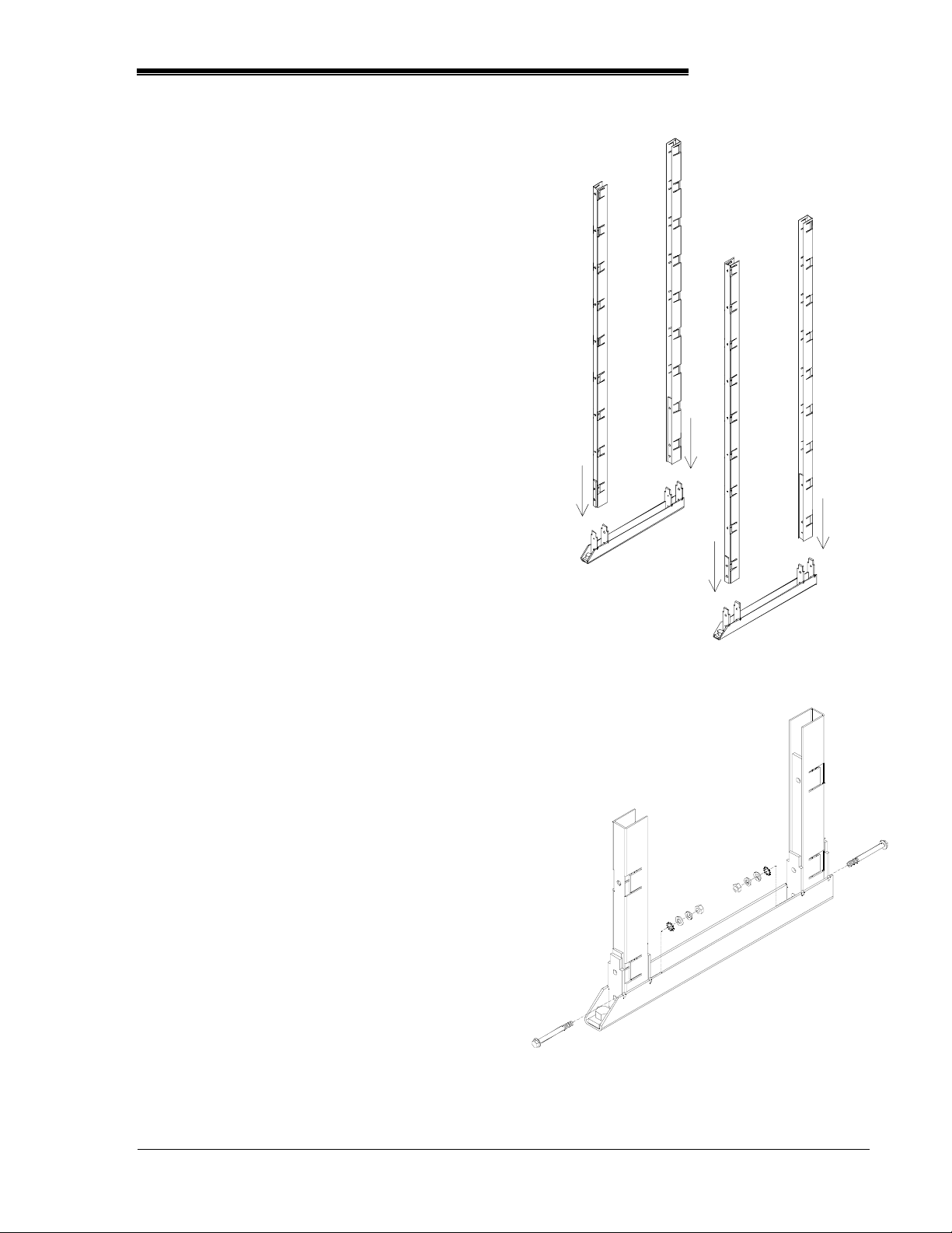
Base Beams
1. LEVEL with customer-supplied floor shims,
and anchor in place. Do NOT torque
anchor bolts until frame assembly is
complete.
2. Install ALL base beams before continuing.
Vertical Channels
1. Insert vertical channels into base beams.
See Figure 9.
2. Bolt vertical channels to base beams. Refer
to below list for hardware order and Figure
10:
• Serrated Hex Bolt (M10x1.5 –
100mm),
• Rack Frame,
• External Tooth Washer,
• Flat Washer,
• Lock Washer,
• Hex Nut
3. Torque all connections (except anchor bolts)
to 40 ft-lbs.
PowerSafe DDm
INSTALL VERTICALS
FIGURE 9
VERTICAL CHANNEL TO BASE
BEAM HARDWARE DETAIL
FIGURE 10
Publication No. US-DDm-IM-003 Page 7
November 2003 www.enersysinc.com
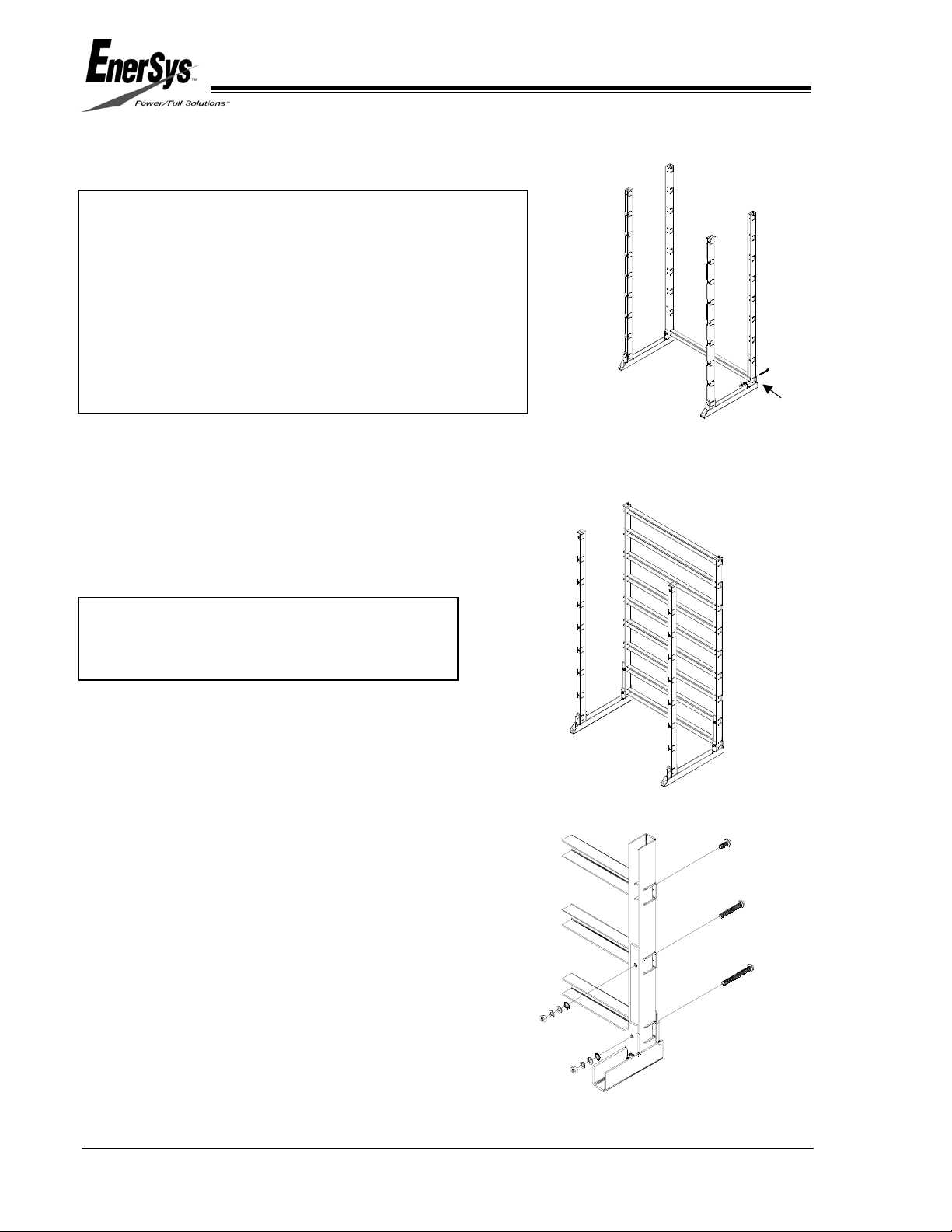
Horizontal Channels
NOTE:
There may be two types of horizontal channels with
your shipment:
1) Rear – have four weld nuts
2) Front – have more than four weld nuts
The front horizontals are universal and, in most
configurations, are substituted for the rear horizontals.
Front horizontals are to be installed with the flange
positioned with the holes facing up.
Starting at the bottom of the REAR verticals:
1. Insert REAR horizontal channels into the
vertical channels. Center the horizontals
between the verticals. See Figures 11a & b.
2. Bolt horizontal channels to vertical channels.
Refer to below list for hardware order and
Figure 12:
NOTE:
The bottom two horizontals require full
thread longer bolts at the vertical channel.
Bottom horizontal:
– Serrated Hex Bolt(M10x1.5 – 100mm
Full Threads),
– Rack Frame,
– External Tooth Washer,
– Flat Washer,
– Lock Washer,
– Hex Nut
Second from bottom horizontal:
– Serrated Hex Bolt (M10x1.5 – 75mm
Full Threads),
– Rack Frame,
– External Tooth Washer,
– Flat Washer,
– Lock Washer,
– Hex Nut
All other horizontals:
– Serrated Hex Bolt (M10x1.5 – 25mm)
3. Finger-tighten connections.
4. Install ALL REAR horizontals before
REAR HORIZONTAL CHANNEL HARDWARE DETAIL
continuing.
INSTALL REAR HORIZONTAL CHANNELS
FIGURE 11A
INSTALL REAR HORIZONTAL CHANNELS
FIGURE 11B
FIGURE 12
Page 8 Publication No. US-DDm-IM-003
www.enersysinc.com November 2003
PowerSafe DDm
Starting at the bottom of the FRONT verticals:
1. Insert FRONT horizontal channels into the
vertical channels. Center the horizontals
between the verticals. See figures 13A &
13B.
2. Bolt horizontal channels to vertical channels.
Refer to below list for hardware order and
Figure 14.
NOTE:
The bottom two horizontals require full
thread longer bolts at the vertical channel.
Bottom horizontal:
– Serrated Hex Bolt (M10x1.5 – 100mm
Full Threads),
INSTALL FRONT HORIZONTAL
CHANNELS
FIGURE 13A
– Rack Frame,
– External Tooth Washer,
– Flat Washer,
– Lock Washer,
– Hex Nut
Second from bottom horizontal:
– Serrated Hex Bolt
(M10x1.5 – 75mm Full Threads),
– Rack Frame,
– External Tooth Washer,
– Flat Washer,
– Lock Washer,
– Hex Nut
All other horizontals:
– Serrated Hex Bolt (M10x1.5 – 25mm)
INSTALL FRONT HORIZONTAL
CHANNELS
FIGURE 13B
3. Finger-tighten connections.
4. Install ALL FRONT horizontals before
continuing.
Publication No. US-DDm-IM-003 Page 9
November 2003 www.enersysinc.com
REAR HORIZONTAL CHANNEL HARDWARE
DETAIL
FIGURE 14
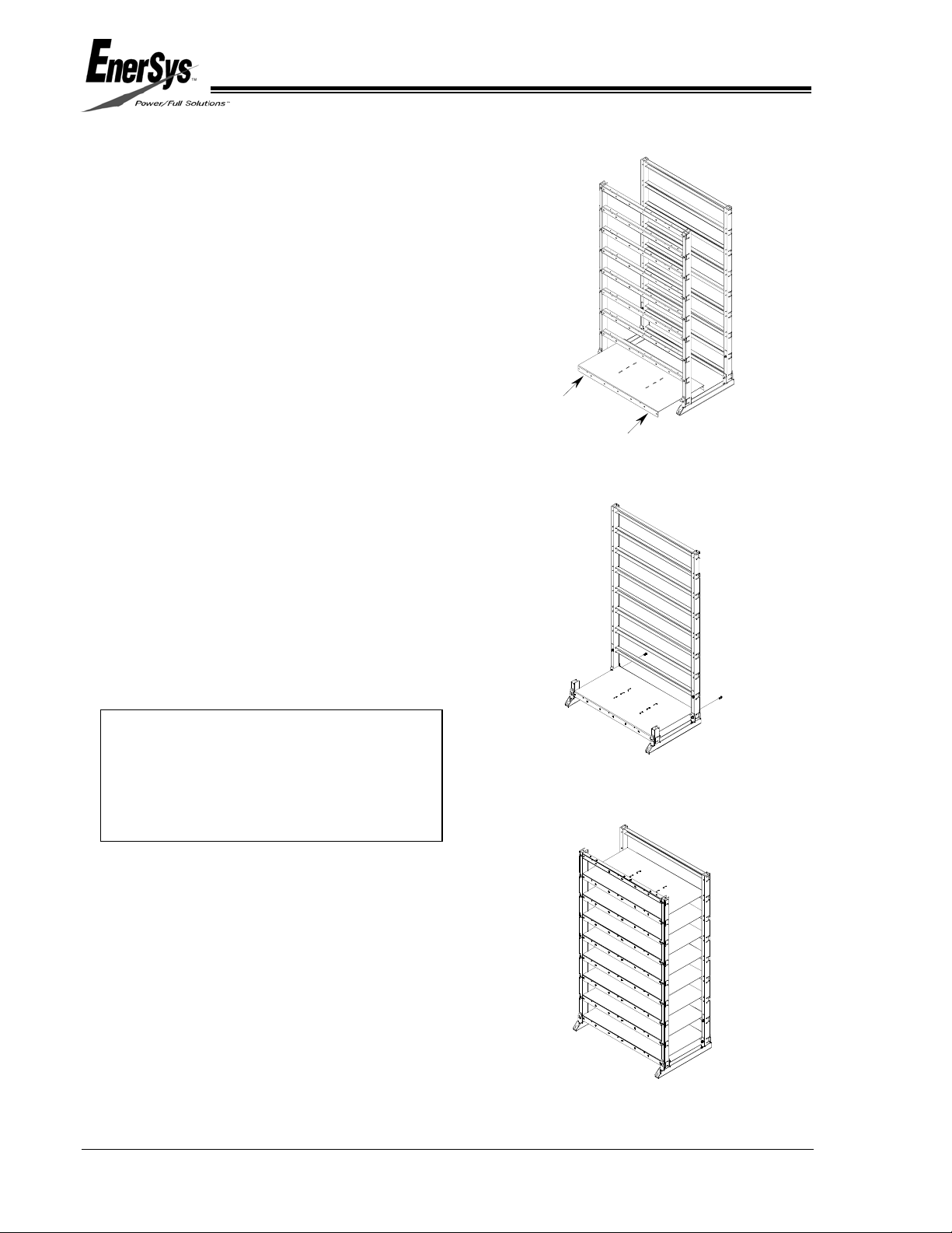
Cell Support Shelves
Starting at the bottom of the rack:
1. Place shelves over FRONT and REAR
horizontals. See Figure 15.
2. Align holes of shelf with holes of horizontal
channels. Bolt the shelf to the REAR
horizontal using (2) M10x1.5 – 25mm
Serrated Hex Bolts in the two OUTSIDE
holes of the shelf. See Figure 16.
3. Torque these bolts to 20 ft-lbs.
4. After ALL shelves for the rack are in place,
position the vertical channels so that the
front and rear horizontals fit tightly against
the shelves. See Figure 17.
5. Torque ALL bolts connecting the horizontals
to the verticals to 20 ft-lbs.
6. If you are installing a MULTI-STACK WITH
ZERO SEPARATION system, repeat
Procedures 1 through 5 until all shelves are
installed.
INSTALL BOTTOM CELL
SUPPORT SHELF
FIGURE 15
NOTE:
MULTI-STACK WITH ZERO
SEPARATION systems are fastened
together at the top front and top rear with
a tie bar.
CELL SUPPORT SHELF
REAR HARDWARE DETAIL
FIGURE 16
7. Torque all anchor bolts according to system
design and manufacturer’s
recommendations.
Page 10 Publication No. US-DDm-IM-003
www.enersysinc.com November 2003
INSTALL CELL SUPPORT
SHELVES
FIGURE 17
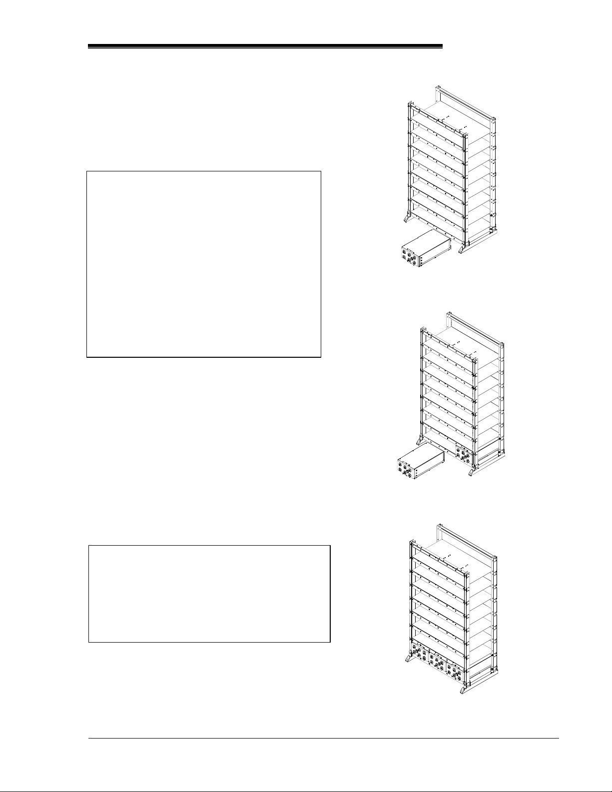
BATTERY CELL INSTALLATION
DDm battery cells are designed for shipment
and use in steel modules.
USE CAUTION WHEN HANDLING THE
DDm MODULES
After a cell has been inserted into a
module at the factory, a loose fit could
develop because of recombination. The
cell could slip very easily from the
module if the module/cell is turned so
that the open end of the module is lower
than the closed end of the module.
Serious personal injury could result if the
cell slides unintentionally from the
module. Keep shipping/installation
retainer in place until modules are safely
positioned on the shelves.
PowerSafe DDm
INSTALL FIRST MODULE
FIGURE 18
1. BEFORE installing the cells, check the
voltages. The minimum acceptable cell
voltage is 2.05 vpc.
If a cell has a voltage below 2.05 vpc, call
your nearest EnerSys sales/service
representative for resolution, or call the
corporate office number listed on the back of
this manual and ask for EnerSys Integrated
Systems & Services.
2. Inspect each terminal for visual signs of
mechanical defects.
INSTALL SECOND MODULE
FIGURE 19
NOTE:
Report any defects to your nearest
EnerSys sales/service representative for
resolution, or call the corporate office
number listed on the back of this manual
and ask for EnerSys Integrated Systems &
Services.
If terminals are acceptable:
3. Place the FIRST DDm module onto the
LOWEST EMPTY shelf, with the terminals
toward the front. See Figure 18.
Publication No. US-DDm-IM-003 Page 11
November 2003 www.enersysinc.com
INSTALL MODULES
FIGURE 20
 Loading...