

Page 1
Alino TL
Power Conditioning Unit
Owner’s Manual
Page 2

About OutBack Power
OutBack Power is a leader in advanced energy conversion technology. OutBack products include true sine wave
inverter/chargers, maximum power point tracking charge controllers, and system communication components, as well
as circuit breakers, batteries, accessories, and assembled systems.
Website: http://www.outbackpower.com
Disclaimer
UNLESS SPECIFICALLY AGREED TO IN WRITING, OUTBACK POWER:
(a) MAKES NO WARRANTY AS TO THE ACCURACY, SUFFICIENCY OR SUITABILITY OF ANY TECHNICAL OR
OTHER INFORMATION PROVIDED IN ITS MANUALS OR OTHER DOCUMENTATION.
(b) ASSUMES NO RESPONSIBILITY OR LIABILITY FOR LOSS OR DAMAGE, WHETHER DIRECT, INDIRECT,
CONSEQUENTIAL OR INCIDENTAL, WHICH MIGHT ARISE OUT OF THE USE OF SUCH INFORMATION. THE
USE OF ANY SUCH INFORMATION WILL BE ENTIRELY AT THE USER’S RISK.
OutBack Power cannot be responsible for system failure, damages, or injury resulting from improper installation of
their products.
Information included in this manual is subject to change without notice.
Notice of Copyright
Alino TL Power Conditioning Unit Owner’s Manual
Trademarks
Alino TL, Alino by OutBack, and the Alino logo are trademarks owned and used by OutBack Power, an EnerSys
company. These trademarks may be registered in the United States and other countries.
© 2019 by OutBack Power. All Rights Reserved.
Date and Revision
March 2019, Revision A
Part Number
900-0248-01-00 Rev A
Page 3

Table of Contents
Symbols Used ........................................................................................................................... 5
General Safety .......................................................................................................................... 5
Introduction .................................................................................................. 7
Audience ................................................................................................................................... 7
Welcome to OutBack Power ..................................................................................................... 7
Product Overview ...................................................................................................................... 7
Features ............................................................................................................................................... 7
Example System ................................................................................................................................... 8
Components .............................................................................................................................. 9
Display Components .......................................................................................................................... 10
Installation ................................................................................................. 11
Dimensions ............................................................................................................................. 11
Preparation ............................................................................................................................. 12
Mounting ................................................................................................................................. 13
Connections ............................................................................................................................ 14
Battery ................................................................................................................................................ 14
AC ....................................................................................................................................................... 16
PV ....................................................................................................................................................... 17
Selecting Modules ......................................................................................................................................... 17
Connecting Modules ...................................................................................................................................... 17
Final Assembly ........................................................................................................................ 18
Remote Display Panel Installation .......................................................................................... 19
Other Communications ........................................................................................................... 20
Operation .................................................................................................. 21
Power ON/OFF ....................................................................................................................... 21
Display Panel .......................................................................................................................... 21
LED Indicators .................................................................................................................................... 21
Buttons ............................................................................................................................................... 22
Display Icons ...................................................................................................................................... 22
Display Readings ................................................................................................................................ 24
Functions ................................................................................................................................ 26
MPPT .................................................................................................................................................. 26
Battery Charging ................................................................................................................................. 27
Three-Stage Charging ................................................................................................................................... 27
Equalization ................................................................................................................................................... 28
Inverting .............................................................................................................................................. 29
Derating ......................................................................................................................................................... 29
Backup Duration ............................................................................................................................................ 30
Transfer .............................................................................................................................................. 30
Settings ..................................................................................................... 31
General Settings ..................................................................................................................... 31
Function Settings .................................................................................................................... 34
USB OTG Functions ........................................................................................................................... 34
Firmware upgrade .......................................................................................................................................... 35
Import settings ............................................................................................................................................... 35
Export data log ............................................................................................................................................... 35
900-0248-01-00 Rev A
3
Page 4

Table of Contents
Output Source Priority Timer .................................................................................................. 36
Charger Source Priority Timer ................................................................................................ 3 7
Auxiliary Contact Settings ....................................................................................................... 38
Troubleshooting .......................................................................................... 39
Errors and Warnings ............................................................................................................... 39
Basic Troubleshooting ............................................................................................................ 41
Specifications ............................................................................................. 43
Device Specifications .............................................................................................................. 43
Regulatory Specifications ....................................................................................................... 44
Certifications ....................................................................................................................................... 44
4 900-0248-01-00 Rev A
Page 5
Important Safety Instructions
READ AND SAVE THESE INSTRUCTIONS!
This manual contains important safety instructions for the Alino product. As with any electrical
equipment, certain precautions must be observed when installing this equipment. To reduce the
risk of personal injury and to ensure safe installation and operation, carefully read and follow all
instructions, cautions and warnings in this manual.
Symbols Used
WARNING: Hazard to Human Life
This type of notation indicates that the hazard could be harmful to human life.
CAUTION: Hazard to Equipment
This type of notation indicates that the hazard may cause damage to
the equipment.
IMPORTANT:
This type of notation indicates that the information provided is important to the
installation, operation and/or maintenance of the equipment. Failure to follow
the recommendations in such a notation could result in voiding the
equipment warranty.
NOTE:
This type of notation indicates that the information provided is important to
understanding the operation and limits of the equipment. Failure to follow the
recommendations in such a notation could result in improper or failed operation.
General Safety
WARNING: Limitations on Use
This equipment is NOT intended for use with life support equipment or other
medical equipment or devices.
WARNING: Explosion, Electrocution, or Fire Hazard
Charge only deep-cycle lead-acid rechargeable batteries. Other battery types
may burst, causing personal injury and damage.
Always use insulated tools.
Avoid dropping tools onto batteries or other electrical parts.
Never charge a frozen battery.
900-0248-01-00 Rev A
5
Page 6

Important Safety Instructions
CAUTION: Equipment Damage
Only use components or accessories recommended or sold by OutBack
Power or its authorized agents.
Follow all wire and cable sizing specifications shown.
All wiring and installation methods must comply with local codes and
regulations.
Do not disassemble this product. If service or repair are required, consult a
qualified service center.
This product must be connected to a permanent grounded wiring system.
Do not reverse the polarity of the battery cables. This will destroy the product.
Ensure that neither the AC nor the DC circuits are allowed to be shortcircuited. Do not connect the system to the utility grid if a short circuit occurs.
This product is not internally isolated. Use it only with single- crystalline,
polycrystalline (class A rated), or copper indium gallium selenide (CIGS)
PV modules. The PV modules should not be grounded.
Use a PV combiner equipped with surge protection. Without this protection,
the product could be subject to lightning damage.
6
900-0248-01-00 Rev A
Page 7

Introduction
Audience
This manual provides instructions for installation, setup, and operation of the product. These
instructions are for use by qualified personnel who meet all local and governmental code
requirements for licensing and training for the installation of electrical power systems with AC
and DC voltage up to 600 volts. This product is only serviceable by qualified personnel.
Welcome to OutBack Power
Thank you for purchasing the Alino TL power conditioning unit. This product combines the
functions of an inverter, uninterruptible power supply (UPS), and charger that can operate from
batteries, utility grid and solar (photovoltaic or PV) power.
Product Overview
Features
o
Pure sine wave inverter
o
Can accept utility grid or generator power
o
Smart battery charger design for optimized battery performance
o
Supports lithium-ion batteries
o
Maximum power point tracking (MPPT) charging from PV
o
Comprehensive detachable display screen with easy navigation
Configurable input voltage range for home appliances and personal computers
Configurable battery charging current based on applications
Configurable AC / PV charger priority
Display module can be set up for remote access
Display information can be seen on mobile phone using Bluetooth app
o
Rugged design with protection against overload, over-temperature, and short circuit
o
Field-upgradable firmware
o
Dual fans with dust filters and individual monitoring
o
Configurable prioritization and usage timer for multiple power sources
o
USB OTG functionality
o
Certified IEC 62109-1:2010 and IEC 62109-2:2011 — Safety of Power Converters for use in
Photovoltaic Systems (2010)
o
EMTEK Certificate of Conformity No. ES181229002P
900-0248-01-00 Rev A
7
Page 8
Introduction
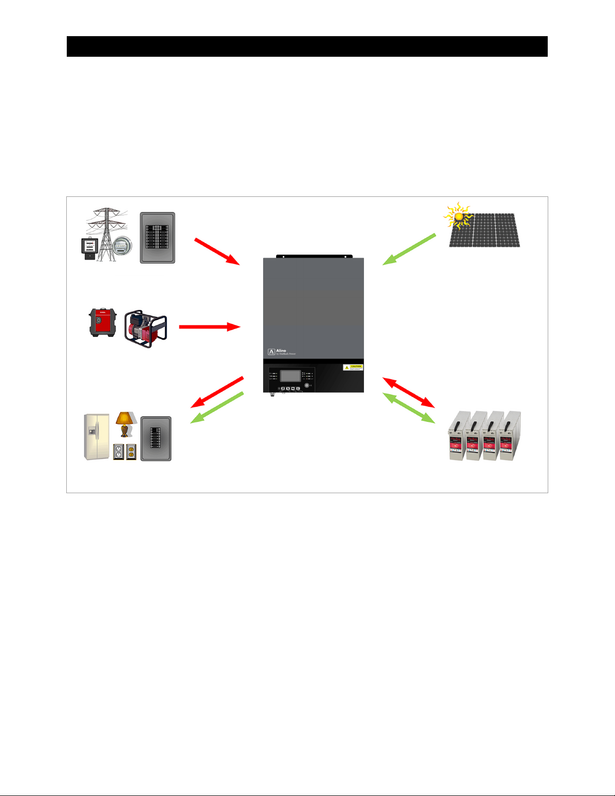
Example System
Figure 1 shows the basic components used in a complete Alino system. For the highest level
of versatility, the system should be equipped with either utility grid or generator input as well as
a PV array.
Other system architectures are possible beyond those shown here. A system integrator can
advise on the best design for a particular requirement.
Figure 1 Example of System
8 900-0248-01-00 Rev A
Page 9
Components
Introduction
1
2
3
4
5
6
7
8
9
10
11
12
Display panel
Removable lower cover
Circuit breaker
Auxiliary dry contacts
USB communication port
BMS communication port
RS-232 communication port
Display communication port
AC input cable opening
AC output cable opening
Battery cable opening
PV cable opening
1
2
3
4
5
9
10
3
7 8
6
11
12
Figure 2 Components
900-0248-01-00 Rev A 9
Page 10
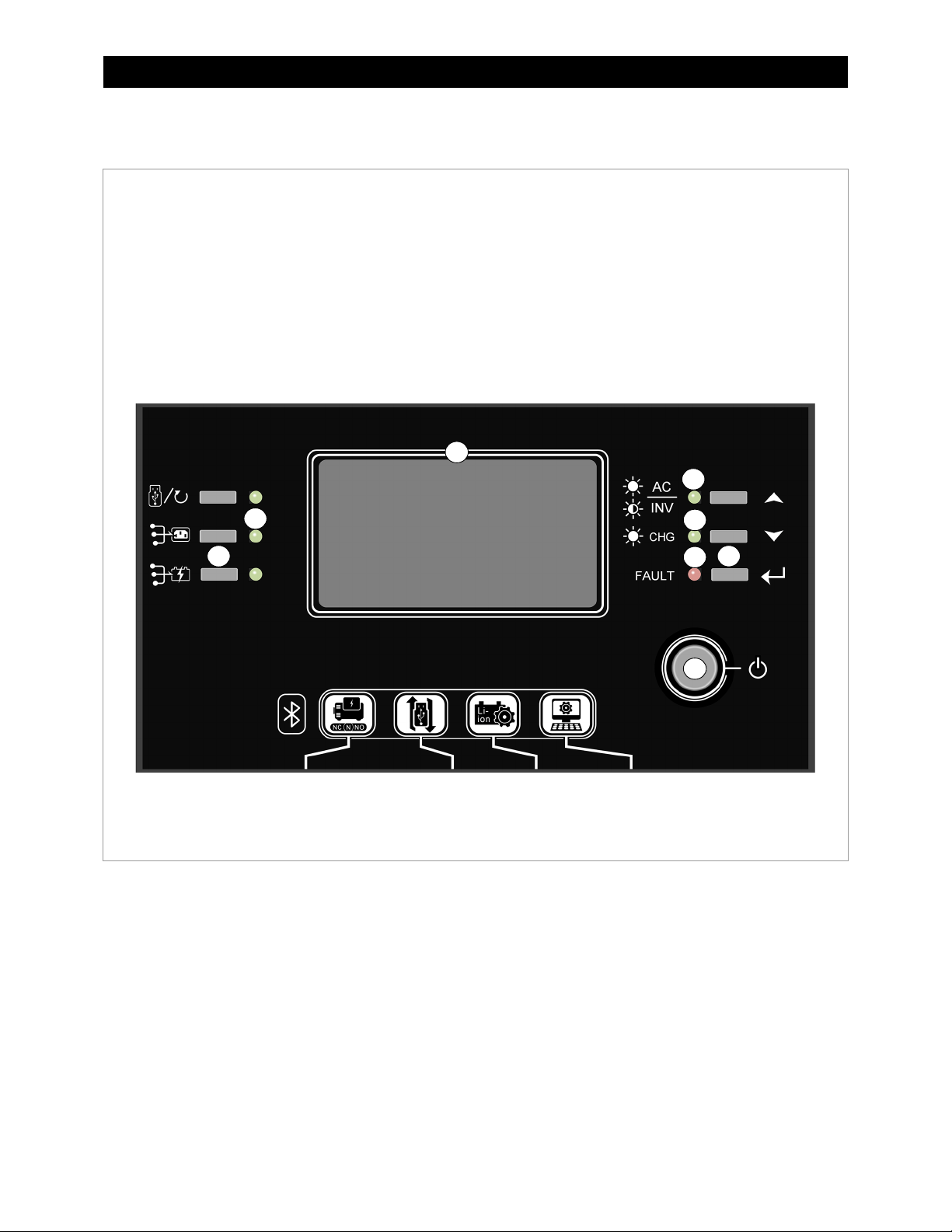
Introduction
Display Components
1
2
3
4
5
6
7
LCD display
Output source LED indicators
Status LED indicator
Charging LED indicator
Fault LED indicator
Function buttons
On/Off button
2
6
1
3
4
6
5
Figure 3 Display Components
7
10 900-0248-01-00 Rev A
Page 11
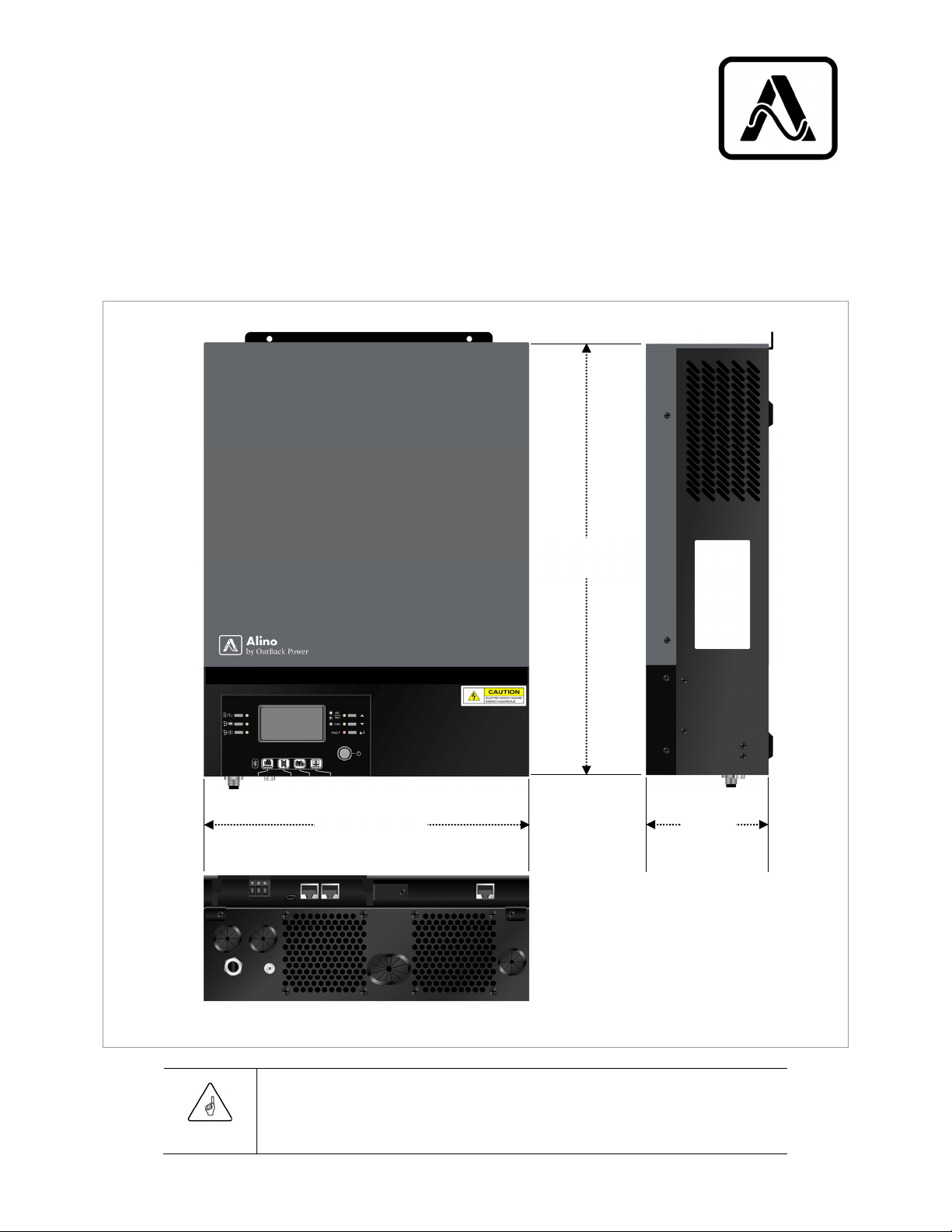
Dimensions
Installation
40.0 cm
(15.7”)
30.0 cm (11.8”)
11.5 cm
(4.5”)4.
Figure 4 Dimensions
IMPORTANT:
For proper ventilation, allow clearances of approximately 20 cm (8") to either side and
50 cm (20") above and below the product.
900-0248-01-00 Rev A
11
Page 12
Installation
Preparation
Remove the lower cover as shown in Figure 5.
1. On the underside of
the unit, remove the
screws holding the
cover in place.
A
2. Loosen the lower cover.
3. Remove the two
communication cables A.
4. Remove the lower cover.
Figure 5 Removing Lower Cover
12 900-0248-01-00 Rev A
Page 13
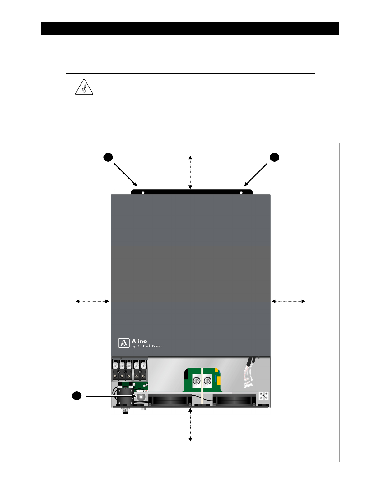
Mounting
(
)
(
)
(8”)
(8”)
IMPORTANT:
Mount this product on a solid surface of concrete or similar non-combustible material.
Install this product at eye level for easy reading of the display panel.
This product will function most effectively if installed upright.
Observe all marked clearance requirements.
Mount this product by inserting screws (M4 or M5 size) at points A, B, and C.
A B
50 cm
20”
Installation
80 cm
C
900-0248-01-00 Rev A
50 cm
20”
Figure 6 Mounting and Clearances
80 cm
13
Page 14
Installation
–
Connections
Battery
To install batteries for this product:
1.
Assemble the batteries in series or parallel as needed for the system nominal voltage.
Install all cables and interconnects.
CAUTION: Hazard to Equipment
Do not reverse the polarity of the positive (+) and negative (–) battery cables.
This will destroy the product. Check the polarity of all connections before applying
battery power.
Do not place any other object or hardware between the inverter terminal surface and the
ring terminal. Overheating may result. This includes antioxidant compound, which must
be applied when connections are complete. See Figure 8 on the next page.
NOTE:
Cables and ring terminals should be sized according to Table 1 on the next page..
Install DC overcurrent protection between this product and the battery. This is
required for both safety reasons and regulatory compliance. A manual disconnect
device may also be required. These devices should be sized according to the cable
size (see Table 1).
Battery management system (BMS) communications, if required, are connected to the
designated BMS port. See Figure 9 on the next page.
For model ATL3024E, minimum recommended battery capacity is 100 Ah. For model
ATL5048E, it is 200 Ah.
2.
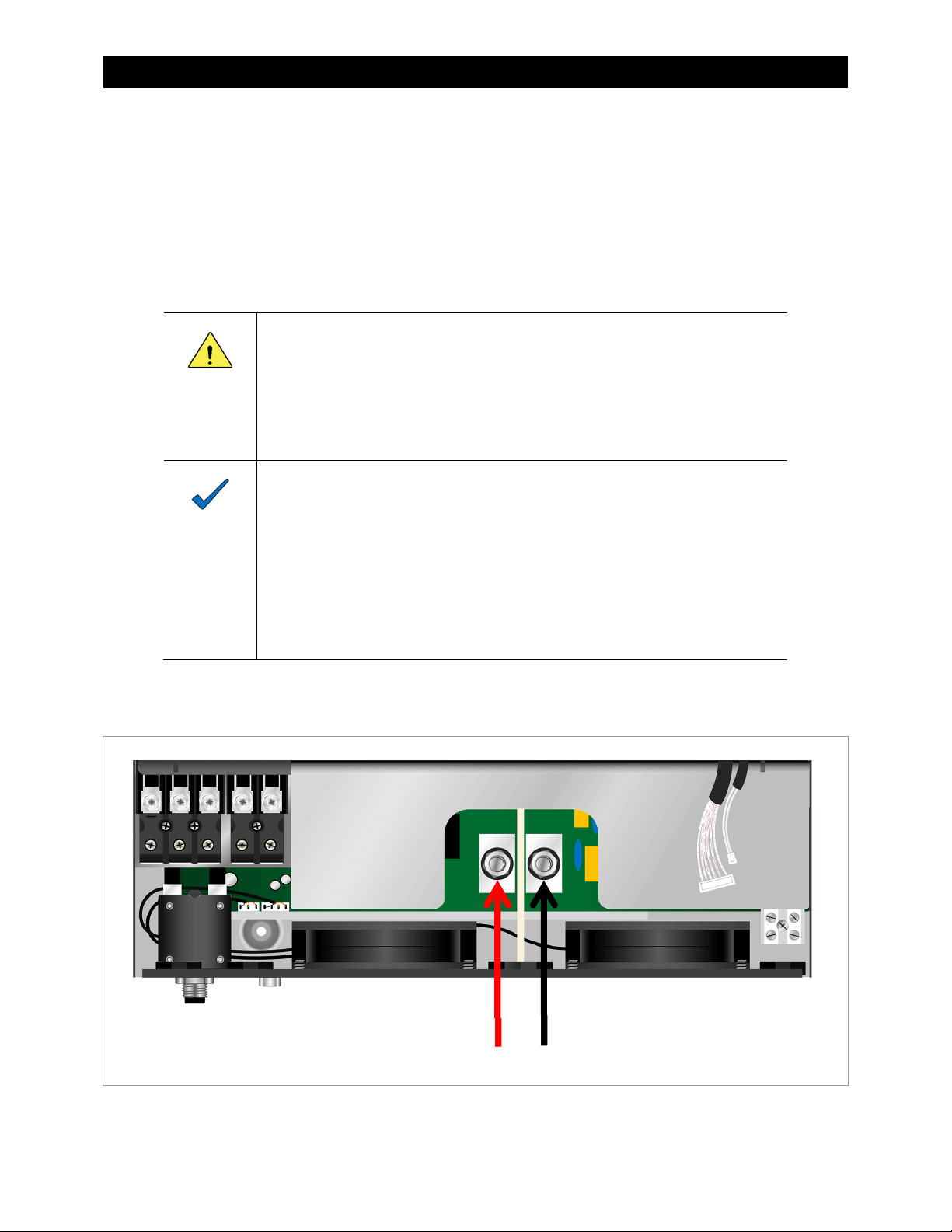
Insert the positive (+) and negative (–) battery cables into the cable opening as shown in
Figure 7. Install the ring terminals on the studs as shown. Observe the polarity.
14
+
Figure 7 Battery Connections
900-0248-01-00 Rev A
Page 15
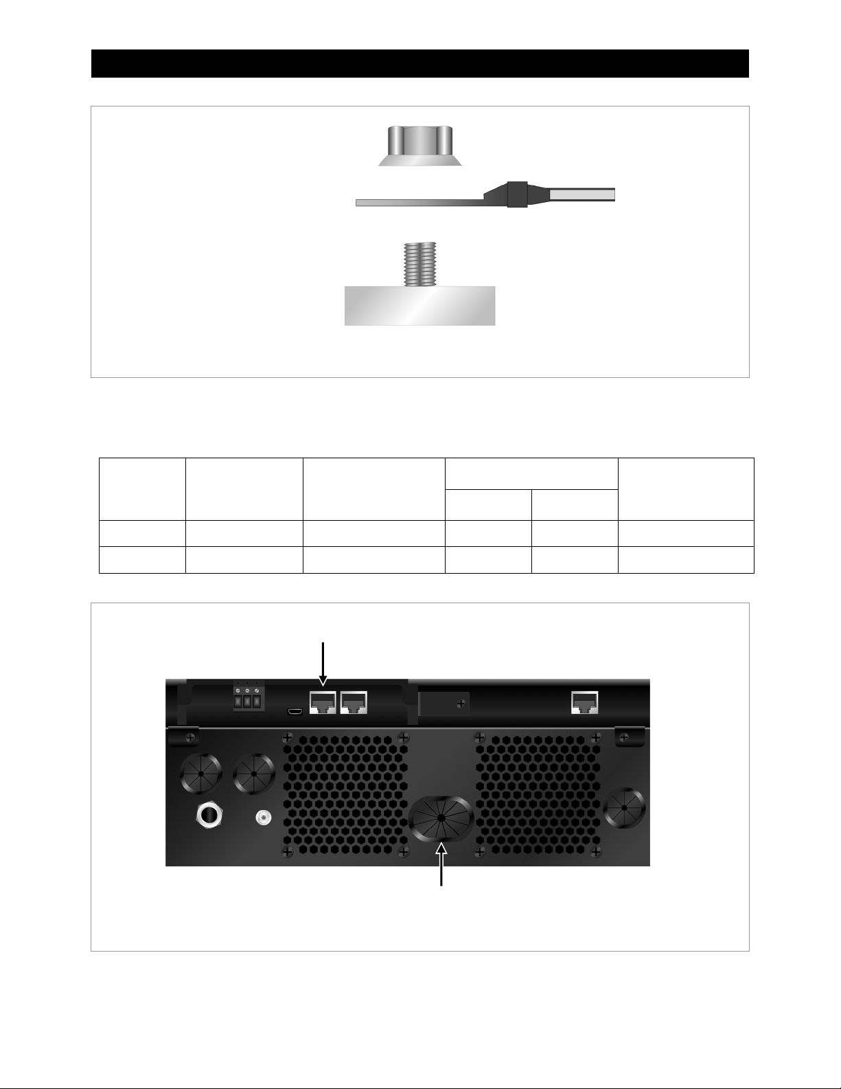
Nut
Battery Ring Terminal
Stud
Inverter Terminal Surface
Figure 8 Battery Terminal Hardware
3. Tighten all connections to the torque values required in Table 1.
Table 1 Battery Conductors
Installation
Model
ATL3024E 142 Adc 38 mm2 (#2 AWG) 8.4 mm 39.2 mm 5 Nm (3.69 in-lb)
ATL5048E 118 Adc 38 mm2 (#2 AWG) 8.4 mm 39.2 mm 5 Nm (3.69 in-lb)
Maximum
Current
Cable Size
BMS Port
Ring Terminal
Diameter Length
Terminal
Torque
Battery Cable Opening
Figure 9 Battery Terminal Features
900-0248-01-00 Rev A 15
Page 16

Installation
W
AC
Before making any connections, open all disconnect devices on both AC and DC sources.
To install AC connections for this product:
NOTE:
AC wires should be sized according to Table 2.
Install a circuit breaker between the AC source and the input terminals. It is needed for
overcurrent protection and also as a manual disconnect device. For model ATL3024E,
the size is 32 Aac. For model ATL5048E, it is 50 Aac.
Do not reverse the connections to the A
connections before applying power.
1.
Remove approximately 10 mm (½”) of the insulation from all AC wires.
2.
Connect the ground (PE) conductor to terminal A.
3.
Connect the input L (line) and N (neutral) conductors to terminals B and C. Connect the
output L and N conductors to terminals D and E. (Use the cable openings as shown.)
4.
Tighten all connections to the torque values required in Table 2.
C IN
and AC OUT terminals. Check all
A
B C
D E
AC Input and
Output Openings
Figure 10 AC Terminals
Table 2 AC Conductors
Model
ATL3024E 4 mm2 (#12 AWG) 1.2 Nm (0.89 in-lb)
ATL5048E 6 mm2 (#10 AWG) 1.2 Nm (0.89 in-lb)
ire Size Terminal Torque
16
900-0248-01-00 Rev A
Page 17

PV
W
–
Selecting Modules
CAUTION: Hazard to Equipment
Do not exceed the maximum Voc under any conditions. This will destroy the product.
IMPORTANT:
Only single-crystalline, multicrystalline (class A rated) or CIGS modules may be used.
When selecting PV modules, observe the following parameters:
o
Maximum permitted open-circuit voltage (Voc) is 500 Vdc
o
Maximum PV array power is 4000 watts
o
Maximum power-point tracking (MPPT) range is 120 to 450 Vdc
o
The Voc should always exceed the battery voltage
Connecting Modules
Installation
NOTE:
PV wires should be sized according to Table 3.
DC overcurrent protection should be installed between the Alino and the PV modules.
A PV combiner with surge protection is recommended.
To install PV modules for this product:
1.
Remove approximately 7 mm (¼”) of the insulation from all PV wires. Optionally, install
bootlace ferrules on the exposed PV wires to assist in connection.
2.
Insert the positive (+) and negative (–) PV wires into the cable opening as shown in Figure
11. Install the PV wires into the terminals as shown. Observe the polarity.
3.
Tighten all connections to the torque values required in Table 3.
+
Figure 11 PV Terminals
PV
Opening
900-0248-01-00 Rev A
Table 3 PV Conductors
Model
ATL3024E 4 mm2 (#12 AWG) 1.2 Nm (0.89 in-lb)
ATL5048E 4 mm2 (#12 AWG) 1.2 Nm (0.89 in-lb)
ire Size Terminal Torque
17
Page 18

Installation
Final Assembly
Replace the lower cover to complete installation.
1. Place the lower
cover near the
Alino housing.
2. Install the two
communication
cables A.
3. Set the lower cover
in place.
4. On the underside of the
unit, attach the screws
to secure the lower
cover in place.
Figure 12 Final Assembly
Installation is complete.
A
18 900-0248-01-00 Rev A
Page 19

Installation
Remote Display Panel Installation
The display panel may be removed and installed at a distance. This may be performed either
before or after the lower cover is replaced.
1. Remove screw A and retaining plate B.
A
2. Slide the display panel out of position.
3. Unplug the RJ-45 cable from the communication port at C.
B
C
D
4. Remove the display panel. Replace the retaining plate B with screw A.
5. Select the place for the panel to be installed. Drill holes and insert screws according to
the E mounting holes. These holes are 70 mm (2.76”) apart.
6. Place the panel on these screws. Add one more screw in location F to secure it.
E
E
F
7. Connect a CAT5 cable between the ports at C and D.
This cable can be up to 15 meters long.
900-0248-01-00 Rev A
C
D
Figure 13 Remote Panel Installation
19
Page 20

Installation
Other Communications
The display can perform several forms of communication.
E
B
A
C
D
Figure 14 Communications Ports and Terminals
Auxiliary (Dry Contact)
For item A, see page 38.
USB
Item B is a Micro-USB B port. It is used for USB connection with a PC.
BMS
Item C is an RJ45 port. It is used for communication with a battery management system (BMS)
to communicate with lithium-ion batteries.
Serial (RS232)
Item D is an RJ45 port. It is used for RS232 communication with a PC. A communications
cable and CD have been included with the Alino product. This CD includes instructions on
installation and operation of the monitoring software.
Bluetooth
The display can use Bluetooth communication to make the display portable at distances of
6 to 7 m (about 20 feet).
20 900-0248-01-00 Rev A
Page 21

Operation
Power ON/OFF
When installation is complete and PV or the utility grid are the power source, the display will turn
on automatically. When batteries are the only power source, press the
on the display.
NOTE:
This product can accept AC power from either the utility grid or a generator.
For simplicity, this manual usually refers to utility power.
On/Off
button 1 to turn
2
3
4
5
6
7
1
On/Off Button
Figure 15 LED Indicators
Display Panel
LED Indicators
The display panel has six LED indicators.
: Green (solid) — loads are powered by utility grid.
2
: Green (solid) — loads are powered by PV.
3
: Green (solid) — loads are powered by battery.
4
: Green (solid) — transfer function is active. See page 30.
5
Green (flash) — transfer is inactive and inverter function is active. See page 29.
: Green (solid) — Battery is fully charged.
6
Green (flash) — Battery is charging.
: Red (solid) — Error (failure). See pages 39 and 40.
7
Red (flash) — Warning. See page 39.
900-0248-01-00 Rev A
21
Page 22

Operation
Buttons
The display panel has six setting and function buttons.
1
2
3
On/Off Button
4
5
6
Figure 16 Buttons
: Escape — exits the present setting.
1
, and 3 are also function keys used to implement special functions:
1, 2
1 — selects the USB OTG functions (see page 34).
2 — sets the timer for the output source priority (see page 36).
3 — sets the timer for the charger source priority (see page 37).
: Goes to the previous selection.
4
: Goes to the next selection.
5
Confirms or enters a selection in the Setting screen mode. This button is also used to enter the
:
6
Setting mode. See page 31.
Display Icons
The LCD display has many icons showing the inverter status and operation.
19
20
7
12
10
8
13
11
9
14
15
Figure 17 Display Icons
22 900-0248-01-00 Rev A
16
18
17
Page 23

Operation
!
RUN TIME EST
: This display section shows the
7
SETTING
followed by the icon. (See 9 and page 31.) This item also shows any warning or error
SETTING
Setting
codes. A Warning code is followed by ⚠. An error code begins with F. See page 39 for more
information on this section.
BATT
AC PV
INPUT
M
kWh
VA
: This display section shows AC input voltage and frequency, PV voltage, charging current and
8
%
Hz
power, and battery voltage. , , or appear, depending on which source is being
BATT
monitored. See page 24 for more information on this section.
OUTPUTBATTTEMP
M
kWh
VA
%
: This display section shows AC output voltage and frequency, load percentage, load in volt-amps
9
C
Hz
and watts, and discharge current. See page 24 for more information on this section. Also, in the
Setting
: This icon indicates that PV is connected. (See 12.)
10
: This icon indicates that the utility grid is connected. (See 13.)
11
: This icon is a DC-DC conversion symbol indicating that the system is harvesting PV energy.
12
The
screen mode, this item shows the value being set. (See page 31.)
indicator means the system is using maximum power point tracking. (See page 26.)
MPPT
This power may be used for several functions. (See pages 27 through 30.)
: This icon is an AC-DC conversion symbol indicating that the utility grid is charging the battery.
13
(See page 27.)
screen mode option numbers. The
AC
PV
Setting
mode is
: This icon is a DC-AC conversion symbol. In a battery-based system, it indicates the inverting
14
function is using battery power to run loads. (See 17 and page 29.) In a non-battery system,
it indicates the system is directly converting PV energy to run loads.
:
15
This icon indicates the estimated battery state of charge. When discharging the batteries,
the number of bars shows the remaining capacity. (The estimate is based on a combination
of battery voltage and load).
o
= 0 to 24%
A
o
A, B
o
A, B, C
o
A, B, C, D
= 25 to 49%
= 50 to 74%
C
A
= 75 to 100%
D
B
When charging (indicated by ), some bars will be on and some will flash. The more bars
that are on, the closer the batteries are to a full charge. When A, B, C, and D are all on, the
batteries are full.
: This icon indicates that the audible alarm is disabled. See page 32.
16
LOAD
: This icon indicates the load level compared to the inverter’s maximum load capacity (0 to 24%,
17
25 to 49%, 50 to 74%, 75 to 100%)
Hi
: This icon indicates the inverter has shut down due to overload. See page 40.
OVERLOAD
18
This icon indicates a USB drive has been connected.
:
19
:
20
This icon indicates Bluetooth service is established.
900-0248-01-00 Rev A 23
Page 24

Operation
Display
Readings
The left side of the LCD display has three fields of readings.
These readings can be switched to display different data.
The and keys (see page 31) proceed through a series
of items. In most cases only two of the three fields are used.
Different markers appear to indicate unit or the type of data.
The items below show examples of each category of display.
The order shown here and on the next page is the order of
the screens when pressing the and keys.
AC
Input and output AC voltage.
V
AC
The marker and the
marker appear in the
INPUT
upper field. The
marker appears in the lower
V
OUTPUT
field. V markers appear for
each field. This is the
default screen.
AC
Input AC frequency (with
decimal) and output AC
Hz
voltage. The upper field
displays the Hz marker.
V
The lower field continues to
display output AC voltage.
PV
PV voltage and output AC
V
voltage. The marker
PV
appears. The upper field
displays a V marker.
V
The lower field continues to
display output AC voltage.
PV
PV current (with decimal) and
A
output AC voltage.
The upper field displays
an A marker.
V
The lower field continues to
display output AC voltage.
PV
W
PV power and output AC
voltage. The upper field
displays a W marker.
The lower field continues to
V
display output AC voltage.
INPUT
OUTPUT
INPUT
OUTPUT
INPUT
OUTPUT
INPUT
OUTPUT
INPUT
OUTPUT
OUTPUT
OUTPUT
BATT
OUTPUT
BATT
OUTPUT
PVBATT
Charging current from AC or
A
PV. The upper field displays
BATT
the marker instead of
INPUT
V
marker, or both, may appear.
. Either the or
AC
PV
The A marker appears.
The lower field continues to
display output AC voltage.
PVBATT
W
Charging power from PV or
AC. Either the or
AC
PV
marker, or both, may appear.
The W marker appears.
V
The lower field continues to
display output AC voltage.
Battery voltage (with decimal).
The upper field displays only
V
BATT
the and V markers.
(See page 23 for the battery
state of charge display.)
V
The lower field continues to
display output AC voltage.
Output frequency (with
V
decimal). This is displayed in
the lower field, which also
displays a Hz marker.
The upper field continues to
Hz
display battery voltage.
24 900-0248-01-00 Rev A
Page 25

Operation
BATT
V
OUTPUT
%
BATT
V
OUTPUT
VA
BATT
V
OUTPUT
k
VA
BATT
V
OUTPUT
W
BATT
V
OUTPUT
kW
BATT
V
BATT
A
900-0248-01-00 Rev A 25
Load in percentage of
inverter capacity. The
lower field displays a %
marker. (See page 23 for
the load level display.)
The upper field continues
to display battery voltage.
Load in volt-amps. The
lower field displays a VA
marker. (See page 23 for
the load level display.)
When the load size
exceeds 1000 VA, the
lower field and marker will
change to
kVA
(with
decimal). This is also
depicted here.
The upper field continues
to display battery voltage.
Load in watts. The lower
field displays a W marker.
(See page 23 for the load
level display.) When the
load size exceeds 1000
watts, the lower field and
marker will change to kW
(with decimal). This is
also depicted here.
The upper field continues
to display battery voltage.
DC discharge current.
The lower field displays the
marker instead of
BATT
OUTPUT
. It also displays
an A marker.
The upper field continues
to display battery voltage.
PV energy and load output
energy in kilowatt-hours.
All three fields are used.
The topmost field shows
the selection of daily energy
(depicted), monthly energy
nON
(
YEA
(
). The total lifetime
screen (in megawatt-hours)
is also depicted (
The middle field shows PV
energy. It displays the
marker and a
Wh
M Wh
The lower field shows
output energy. It displays
Wh
PV
the marker and a
(or
M Wh
Date. The top field shows
the year (two digits only).
The middle field shows the
month. The lower field
shows the day. (See page
33 to set the date.) No
markers are used.
Time. The upper field
shows the hour (using
a 24-hour clock). The
lower field shows the
minute. (See page 33 to
set the time.) No markers
are used.
Firmware version. Three
screens are available. The
first is for the main CPU
firmware (U1, depicted).
The others are for the
secondary CPU (U2) and
Bluetooth (U3). No
markers are used.
OUTPUT
OUTPUT
PV
PV
kWh
kWh
M
M
), or yearly energy,
tOL
).
(or
kWh
) marker.
kWh
) marker.
PV
Page 26

Operation
p
Functions
The Alino can perform a number of functions, most of which work together. These functions,
and their combinations, are represented on the LCD display by icons (as defined on page 22.)
Figure 18 Icons and Functions
MPPT
The Alino can harvest energy from a photovoltaic (PV) array for several purposes. It harvests
PV energy using maximum power point tracking (MPPT) technology.
A PV array does not produce a linear amount of power. The power it delivers follows a curve
between the open-circuit voltage (Voc) and the short-circuit current (Isc). The power delivery
depends on the array’s load and other factors. The Alino places a variable load on the array
and tracks the result to determine the point of maximum power (V
) between Voc and Isc.
mp
MPPT maintains this process so that it can deliver maximum power regardless of the conditions.
MPPT also converts the PV voltage to a DC level usable by the inverter and batteries.
Isc
CURRENT
VOLTAGE
On the display, MPPT and DC-DC conversion
are represented by this series of icons.
I-V Curve
Available
Power
V
OC
MPPT
Isc
I
CURRENT
V
VOLTAGE
The arrows to the right lead to battery charging
and other functions.
m
V
OC
Figure 19 MPPT
26
900-0248-01-00 Rev A
Page 27

Operation
t
Battery Charging
The Alino can convert incoming power to charge the batteries. When charging from PV power,
the process is represented by the A series of icons. When charging from the utility grid, it is
represented by the B series of icons. Both are possible at once (C).
MPPT
A B C
BYPASS
MPPT
BYPASS
Figure 20 Battery Charging
BYPASS
indicates that the transfer circuit (see page 30) can support loads while charging.
NOTE:
The charger can operate if the Alino is not turned on. It can also operate if the system is shut
down with an error code.
Three-Stage Charging
This charger follows a cycle of three stages: Bulk, Absorption, and Float.
o
Bulk: The first stage. It is a constant-current (C.C.) stage which drives the battery voltage to the
Bulk voltage set point. It typically charges the batteries to between 75% and 90% of their capacity.
See item 26 on page 32.
o
Absorption: The second stage. It is a constant-voltage (C.V.) stage with variable current which
holds the batteries at the Bulk voltage. The length of this stage is the duration of the Bulk stage
multiplied by ten. (It has a minimum time of 10 minutes and a maximum of 8 hours.) Absorption
charges the batteries to 100% of their capacity.
o
Float: The third stage. It is a C.V. stage which maintains the batteries in a fully-charged state.
See item 27 on page 32.
VOLTAGE
CURRENT
Bulk Set Poin
Float Set Point
Bulk
Figure 21 Three-Stage Charging
900-0248-01-00 Rev A
Battery Voltage
Charge Current
Absorption
Float
Maximum
Charge
Current
TIME
27
Page 28

Operation
Equalization
Equalization is a controlled overcharge for battery maintenance. It brings the batteries to a
much higher voltage than usual and maintains them there for a time. This removes inert lead
sulfate compounds from the battery plates. It reduces stratification by circulating the electrolyte.
See items 30 through 36 on page 33 for setting and controlling equalization.
Equalization can be either started manually (item 36) or on an automatic “interval” basis
(item 35). Equalization begins when the interval expires and the charger is in float stage.
The equalization cycle is similar to the normal three-stage cycle. The Equalization voltage
1
3
(item
Absorption time. The charger will return to the Float stage once equalization is complete.
The timer is a C.V. stage which requires the batteries to be held at the Equalization voltage for
the entire time. If the voltage drops below this level, the time will be extended to ensure that this
occurs. The time will only be extended until the Equalization Timeout (item 34) is reached.
The charger will then return to Float to prevent battery damage.
) takes the place of the Bulk voltage. The Equalization time takes the place of the
28 900-0248-01-00 Rev A
Page 29

Operation
r
r
Inverting
The Alino can convert DC power to AC output. In a battery-based system, to “invert” means to
convert battery power to run loads. This is represented onscreen by the A series of icons. In a
system without the use of batteries, the Alino can convert PV power to AC output, assisted by
the utility grid. This is represented by the B icons.
Note that in the absence of batteries or grid, the Alino is still capable of running loads with PV
power alone (C). This is not considered a stable mode of operation, as performance depends
directly on the sun. However, it may be useful in the short term or in emergency situations.
A B
LOAD
MPPT
BYPASS
LOAD
MPPT
C
LOAD
Figure 22 Inverting
Derating
If the AC input voltage drops to 170 Vac, the output power will be derated as depicted on the
graph below.
OUTPUT
POWER
Rated Powe
50% Powe
INPUT
90 Vac 170 Vac
280 Vac
VOLTAGE
Figure 23 Derated Output
NOTES:
When PV is the only input source (no batteries or grid), the ATL5048E output is limited to
4 kW. This is the size of the maximum permitted PV input.
900-0248-01-00 Rev A
29
Page 30

Operation
Backup Duration
This table estimates the operating time (in minutes) of a battery backup system based on
inverter model, size of load, and battery bank capacity.
Table 4 Estimated Backup Duration
Model
Load
(VA)
Time (min)
100 Ah 200 Ah 100 Ah 200 Ah
300 449 1100
Model
Load
(VA)
500 613 1288
Time (min)
600 222 525 1000 268 613
900 124 303 1500 158 402
1200 95 227 2000 111 271
1500 68 164 2500 90 215
ATL3024E
1800 56 126 3000 76 182
ATL5048E
2100 48 108 3500 65 141
2400 35 94 4000 50 112
2700 31 74 4500 44 100
3000 28 67 5000 40 90
3200 25 61 5200 38 85
: Exact backup duration depends on the type, age, and quality of the battery. Duration is also affected by
NOTE
many other factors that cannot be displayed here.
Transfer
When connected to the utility grid, the Alino uses a transfer relay to send grid power directly to
the loads. To prevent backfeed, this relay opens when the utility grid is not present or when the
inverter is forced to disconnect.
This function can assist the PV input. If
SUb
is selected in item
1
0
(see page 31) and the PV is
not sufficient, the grid will assist with loads (as well as charging batteries). This is shown by the
series of icons. With no PV present (at night), grid will run loads and charge (the B icons).
A
MPPT
A
BYPASS
B
BYPASS
LOAD
LOAD
MPPT
C
BYPASS
D
BYPASS
LOAD
LOAD
Figure 24 Transfer
In systems with no battery, selecting
SUb
in item
loads if the PV is not sufficient (the C icons) or if the PV is not present (the D icons).
30 900-0248-01-00 Rev A
1
0
will still allow the utility grid to assist the
Page 31

General Settings
Settings
1
2
3
4
5
6
7
8
9
Figure 25 General Setting Items
To enter the
Setting
buttons 4 and 5 proceed up and down through the following table. Pressing 6 a second time
allows the selected item to be set with 4 and 5.
To exit a selected item, press 6 again. To exit the Setting mode, press the
The
Setting
(and sometimes 8) displays the selection.
9
The
Item
mode is displayed in items 7, 8, and 9. 7 displays the numbered program item.
column below also shows the default selection.
screen mode, press and hold button 6 for up to 3 seconds. In this mode,
Escape
button 1.
Table 5 General Settings
Item Description
00
ESC
USb
900-0248-01-00 Rev A
Exit the
Output Source Priority setting. If multiple power sources are available, this controls which source is used
first to power the loads. This item can be set to change depending on time of day. (See page 36.)
Selections:
USb
0 1
02
60
is not available.
SUb
Batteries will be used if neither PV nor grid is available.
SbU
PV. Utility is only used if the battery drops to the low battery warning voltage (see page 43), or if
battery voltage drops to the grid transfer voltage in item
the battery transfer setting (item
Maximum charging current (total for PV + utility sources). Selections: 10 to 80 Adc.
Setting
screen mode.
USb, SUb, SbU
(utility, solar, battery): Utility power is used first. PV and battery provide power only when utility
(solar, utility, battery): PV (solar) power is used first. If it is not enough, utility power assists PV.
(solar, battery, utility): PV (solar) power is used first. If it is not enough, battery power assists
.
1 3
) is reached.
1 2
. It will return to using PV or battery once
31
Page 32

Settings
Table 5 General Settings
Item Description
03
APL
05
AGn
06
Lrd
07
trd
09
50
1 0
230
1 1
30
1 2
23.0
46.0
1 3
27.0
54.0
1 6
SNU
1 8
bOF
1 9
ESP
20
LON
22
AON
23
byd
25
FEN
26
Cv
28.2
56.4
27
FLv
57.0
54.0
Acceptable AC (utility) input voltage range. Selections: 90 to 280 Vac (
Battery type. Selections:
USE
If
Auto restart when overload shutdown occurs. Selections: Disable (
Auto restart when over-temperature shutdown occurs. Selections: Disable (
Output frequency. Selections: 50 Hz or 60 Hz. This item chooses the inverter’s AC output frequency.
Output voltage. Selections: 220 Vac, 230 Vac, or 240 Vac. This item chooses the inverter’s nominal
AC output voltage.
Maximum charge current (from the utility grid). Selection range: 2 to 60 Adc.
If item 02 is less than item 11, the setting for 02 will be used.
Grid transfer voltage. If Item
reaching this low-battery voltage.
Selections (model TL3024E): 22.0 Vdc to 25.5 Vdc
Selections (model TL5048E): 44.0 Vdc to 51.0 Vdc
Battery transfer setting. If the Alino transferred to use the grid after reaching the voltage in item
return to using batteries or PV power upon reaching this high-battery setting.
Selections (model TL3024E):
Selections (model TL5048E):
Charger Source Priority setting. If multiple power sources are available, this item controls which source is
used first to charge the batteries. This item can be set to change depending on time of day. (See page 37.)
Selections:
CSO
SNU
OSO
Alarm control. Selections:
When enabled, this alarm causes the unit to beep due to item 22 or when a fault occurs. (See page 39.)
Return to default display. Selections:
default display after 1 minute if no button is pressed, or to remain on the current screen.
Backlight control. Selections:
Unit beeps when the primary source (according to item
Selections:
Overload bypass. Selections:
when item
Record fault codes. Selections:
Bulk charging voltage. This is the setting for the main stages of constant-voltage (CV) charging. (See
page 27.) This is settable when item 05 is set to
Selection range (model TL3024E): 25.0 to 31.5 Vdc
Selection range (model TL5048E): 48.0 to 61.0 Vdc
Float charging voltage. This is the setting for the float stage of charging. (See page 27.) This is settable
when item 05 is set to
Selection range (model TL3024E): 25.0 to 31.5 Vdc
Selection range (model TL5048E): 48.0 to 61.0 Vdc
is selected, battery charging and low DC cutoff voltages can be set in items 26, 27, and 29.
CSO, SNU, OSO
(charge solar) uses PV as first priority. Utility is used only if PV is not available.
(solar and utility) charges with both sources as available.
(only solar) charges only with PV, regardless of utility.
AON
0 1
is set to
AGn
0 1
bOF
(Alarm on),
SbU
USE
(AGM),
is set to
(alarm off),
LON
AOF
byd
. If overload shutdown occurs while using batteries, unit switches to the grid.
FEN
.
FLd
(flooded),
SbU
, this function transfers the Alino to use the grid upon
FUL
(full) to 29.0 Vdc
FUL
(full) to 58.0 Vdc
.
bON
ESP
(auto return),
(Light on),
(Alarm off).
(Bypass disabled),
(Record enabled),
LOF
USE
(user-defined).
(alarm on). Turns audible alarm on or off (see page 23).
rEP
(Light off). Turns the display backlight on or off.
0 1
) is interrupted.
byE
(Bypass enabled). This function operates
FdS
USE
.
APL
) or 170 to 280 Vac (
Lrd
) or Enable (
trd
(remain). Sets the screen to return to the
(Record disabled).
lre
).
) or Enable (
tre
1 2
UPS
).
, it will
).
32 900-0248-01-00 Rev A
Page 33

Operation
Table 5 General Settings
Item Description
Low battery cut-out voltage. This is the low battery voltage setting which shuts down the inverter. This is
29
COv
2 1.0
42.0
30
EEN
3 1
Ev
29.2
58.4
33
60
34
120
35
30d
36
AdS
37
Nrt
93
Nrt
94
10
95
nIN
96
HOU
97
dAY
98
Non
99
yEA
settable when item 05 is set to
: This item shuts down only the inverting function. If this function shuts down due to low battery
NOTE
cut-out, the charger, transfer, and other functions will still work, as will the display.
Selection range (model TL3024E): 25.0 to 31.5 Vdc
Selection range (model TL5048E): 48.0 to 61.0 Vdc
Equalization function. (See page 28.) Selections:
Allows equalization to take place automatically. This item is settable when item 05 is set to either
FLd
Equalization charging voltage. This is the setting for equalization once enabled in item 30 or item 36.
(See page 28.)
Selection range (model TL3024E): 25.0 to 31.5 Vdc
Selection range (model TL5048E): 48.0 to 61.0 Vdc
Equalization time. This timer begins running once item 31 is reached. (See page 28.)
Selection range: 5 to 900 minutes.
Equalization timeout. The maximum time permitted for equalization. (See page 28.)
Selection range: 5 to 900 minutes.
Equalization interval. The days between automatic equalization cycles. (See page 28.)
Selection range: 0 to 90 days.
Immediate equalization. The main display reads Eq. (See page 28.) Selections:
AdS
This is usable when 30 is set to
If
Reset
Erase data log (all accumulated data). Selections:
Data log storage period. During this period, the Alino logs 1000 status items (voltage readings, etc.) for
analysis. The resulting data is more general if taken across a wider time period. It is more specific if taken
across a narrower period. Selection range: 3 to 60 days.
Time (minute) setting. Selection range: 00 to 59.
Time (hour) setting. This product uses a 24-hour clock. Selection range: 00 to 23.
Date (day) setting. Selection range: 00 to 31.
Date (month) setting. Selection range: 00 to 12.
Date (year) setting. Only two digits are used. Selection range: 17 (2017) to 99 (2099).
USE
or
(Disabled).
AdS
PV accumulation kWh data.
.
is selected, it will cancel equalization until the next automatic cycle based on item 35.
USE
.
EEN
Selections:
.
EEN
Nrt
(Not reset),
Nrt
(Equalize enabled),
rSt
(Reset).
(Not reset),
rSt
(Reset).
EdS
(Equalize disabled).
AEN
(Enabled),
900-0248-01-00 Rev A 33
Page 34

Settings
Function Settings
USB OTG Functions
Several aspects of the Alino can be controlled by inserting a USB device loaded with the
appropriate firmware. See page 9 for the location of the port.
If there is a problem with the USB device, the display may show errors
See page 40 if this occurs.
1
2
3
7
8
U01, U02
4
5
6
, or
U03
.
9
Figure 26 USB OTG Setting Items
To enter the USB OTG functions, insert the USB device and press button 1 for 3 seconds.
Screen items 7, 8, and 9 will show these options.
UPG
SEt
LOG
Each of these options is selected with a different button.
34 900-0248-01-00 Rev A
(upgrade the firmware)
(import new settings)
(export data log)
Page 35

Operation
Firmware upgrade
The Alino’s internal firmware can be upgraded by installing the new version from a USB device.
To upgrade the firmware:
1. Press button 1 to select the upgrade function.
2. When the firmware upgrade is ready, item 9 will display rdY (ready). Press button 1 again
to confirm.
3. Press 2 (Yes) to proceed with the upgrade. (The upgrade will proceed automatically.)
Press 3 (No) to cancel the upgrade process.
4. Press 1 to exit when finished with the process.
Import settings
The Alino can import settings that were saved from an older configuration or another inverter.
These settings will replace the present configuration.
To rewrite these settings:
1. Press button 2 to select the import function.
2. When the rewriting process is ready, item 9 will display rdY (ready). Press button 1 again
to confirm.
3. Press 2 (Yes) to proceed with the importing process. (It will proceed automatically.)
Press 3 (No) to cancel the importing process.
4. Press 1 to exit when finished with the process.
Export data log
The Alino’s recorded data can be exported to the USB drive in the form of a data log.
To export the data log:
1. Press button 3 to select the exporting function.
2. When the rewriting process is ready, item 9 will display rdY (ready). Press button 1 again
to confirm.
3. Press 2 (Yes) to proceed with the rewriting process. (It will proceed automatically.)
Press 3 (No) to cancel the rewriting process.
4. Press 1 to exit when finished with the process.
900-0248-01-00 Rev A 35
Page 36

Settings
Output Source Priority Timer
The Alino can switch between Output Source Priority settings (see
1
2
3
4
7
5
8
6
9
0 1
on page 31) on a timer.
Figure 27 Output Priority Timer Setting Items
When using multiple sources to support loads, the priority of the source usage (
SbU
) can be set to change automatically by time of day. For example, during daylight hours
the system can be set to
SbU
. The inverter will run loads from PV or battery power only.
Utility is used only as a last resort. Then during night hours, the system can be set to
which runs loads primarily from utility power.
To set the Output Source Priority Timers:
USb, SUb
USb
, or
,
1. Press and hold button 2 for 3 seconds. Screen items 7, 8, and 9 will show these options.
USb (utility, solar, battery)
SUb
SbU
2. The USb, SUb, or SbU options are set independently for different blocks of time using
buttons 1, 2, and 3. When each button is pressed, the results will appear in this format.
USb (selection)
(solar, utility, battery)
(solar, battery, utility)
00 (start time)
23 (end time)
3. To change USb settings, press button 1. Once selected, the start and end times can be
set using buttons 4 and 5. The setting range is from 00 to 23 in increments of one hour.
Press button 6 to confirm the setting.
4. To change SUb settings, press button 2. Once selected, the start and end times can be
set using buttons 4 and 5. The setting range is from 00 to 23 in increments of one hour.
Press button 6 to confirm the setting.
5. To change SbU settings, press button 3. Once selected, the start and end times can be
set using buttons 4 and 5. The setting range is from 00 to 23 in increments of one hour.
Press button 6 to confirm the setting.
36 900-0248-01-00 Rev A
Page 37

Charger Source Priority Timer
The Alino can switch between Charger Source Priority settings (see
Operation
6
1
on page 32) on a timer.
1
2
3
4
7
5
6
8
9
Figure 28 Charger Priority Timer Setting Items
When using multiple sources to support loads, the priority of the source usage (
OSO
the system can be set to
hours, the system can be set to
) can be set to change automatically by time of day. For example, during daylight hours
0SO
. The inverter will charge batteries PV only. Then during night
SNU
, which charges from all sources, including utility power.
CSO, SNU
To set the Charge Source Priority Timers:
1. Press and hold button 3 for 3 seconds. Screen items 7, 8, and 9 will show these options.
CSO (charge solar)
SNU
OSO
(solar and utility)
(solar only)
, or
2. The USb, SUb, or SbU options are set independently for different blocks of time using
buttons 1, 2, and 3. When each button is pressed, the results will appear in this format.
SNU (selection)
00 (start time)
23 (end time)
3. To change CSO settings, press button 1. Once selected, the start and end times can be
set using buttons 4 and 5. The setting range is from 00 to 23 in increments of one hour.
Press button 6 to confirm the setting.
4. To change SNU settings, press button 2. Once selected, the start and end times can be
set using buttons 4 and 5. The setting range is from 00 to 23 in increments of one hour.
Press button 6 to confirm the setting.
5. To change OSO settings, press button 3. Once selected, the start and end times can be
set using buttons 4 and 5. The setting range is from 00 to 23 in increments of one hour.
Press button 6 to confirm the setting.
900-0248-01-00 Rev A 37
Page 38

Settings
Auxiliary Contact Settings
Figure 29 shows a set of dry contacts (3 ampere, 250 Vac) which are controlled by battery
voltage and charging. These terminals can serve as a switch for auxiliary devices to indicate
low voltage and other situations.
A
Normally closed (NC)
Common (C)
B
A
B C
Normally open (NO)
C
Figure 29 Auxiliary Dry Contact Terminals
Table 6 Auxiliary Dry Contact States
Unit
Status
Power Off Unit is off and no output is powered. Close Open
Output is powered from utility grid. Close Open
Item
(utility grid first);
see page 31
Power On
Output is powered
from either battery
or PV energy
Item
SbU
utility grid only in
emergency); see
page 31
Condition
0 1
0 1
(solar priority,
USb
set as
is set as
Battery voltage < low
battery warning voltage
(See page 43.)
Battery voltage > Setting
value in item 13 (see
page 32) or battery
charging has reached
float stage (see page 27)
Battery voltage < Setting
value in item
(see page 32)
Battery voltage > Setting
value in item 13
(see page 32) or battery
charging has reached
float stage (see page 27)
12
NC & C NO & C
State
Open Close
Close Open
Open Close
Close Open
38 900-0248-01-00 Rev A
Page 39

Troubleshooting
Errors and Warnings
The Alino has indications for fault (“error” or “warning”) conditions. An error is defined as a
critical fault that shuts the unit down. A warning is a non-critical fault that allows the unit to
continue operating. Some warnings may become errors if unattended.
Faults are shown on the front panel. The red LED indicator flashes to indicate a warning and
is solid to indicate an error. The indicator is accompanied by codes on the display. A warning
code (unit still operating) is followed by
are accompanied by an audible alarm, if enabled.
An error code (unit failure) begins with
.
⚠
Code
Fault
Indicator
F
All faults
.
Figure 30 Error and Warning Indications
Table 7 Warning Codes (with alarm)
Code Beep Reason for Warning
01
02
03
04
07
1 0
1 5
1 6
32
Eq
bP
900-0248-01-00 Rev A
3 times per second One of the unit’s fans has failed.
None Temperature is too high.
Once per second Battery voltage is too high. See page 43.
Once per second Battery voltage is too low. See page 43.
Once every 2 seconds Overloaded output (timeout is in progress)
Twice every 3 seconds Output power has been derated due to conditions.
Twice every 3 seconds PV energy is low.
None High AC input voltage (<280 Vac).
None Internal communications interrupted.
None Battery equalization is occurring.
None Battery is not connected.
NOTE:
Certain warning codes, particularly the last two, are not true faults. They simply note
operation outside of what is considered “normal” for the Alino.
39
Page 40

Troubleshooting
Table 8 Error Codes (with unit failure and alarm)
Code Reason for Failure Notes
F01
F02
F03
F04
F05
F06
F07
F08
F09
F51
F52
F53
F55
F57
F58
F59
Both of the unit’s fans have failed. This may require service.
Temperature is too high.
Battery voltage is too high. This can be corrected externally.
Battery voltage is too low. This can be corrected externally.
Output is short-circuited, or internal over-temperature
is detected.
Output AC voltage is too high. This may require service.
Overloaded output (timeout has expired) or
overloaded PV input.
Internal bus voltage is too high. This may require service.
Internal bus soft start failed. This may require service.
Overloaded output. This can be corrected externally.
Internal bus voltage is too low. This may require service.
Incorrect voltage is present at AC output. This may require service.
Unbalanced AC output. This may require service.
Current sensor failed. This may require service.
Output AC voltage is too low. This may require service.
PV input voltage is too high. This can be corrected externally.
The unit will recover after reaching the set
point in item 07. (See page 32.)
This may be able to be corrected externally.
The unit will recover after reaching the set
point in item 06. (See page 32.)
Table 9 USB Fault Codes
Code Reason for Failure
U0 1
U02
U03
No USB device detected.
Device is copy-protected.
Device contains a document with the wrong format.
NOTE:
These codes may appear when a USB device is inserted and a problem is detected.
They appear for 3 seconds before the display returns to the main screen.
Fault codes
(error or
warning)
displayed here
AC LED Indicator
Fault LED Indicator
Circuit
Breaker
Figure 31 Troubleshooting Features
40
900-0248-01-00 Rev A
Page 41

Troubleshooting
Basic Troubleshooting
These is a list of common symptoms (including LED indications and fault codes). Possible
causes and remedies are listed for each symptom. Note that many items indicate unit failure
and require return to a service center.
The error codes from Table 8 are also included here with additional explanation.
Table 10 Troubleshooting
Symptom Indications Possible Cause Possible Remedy
Unit shuts down
automatically after
applying power.
No response after
applying power.
AC input is present
but unit continues
to operate on
battery power.
LCD screen, LED
indicators, and audible
alarm are active for 3
seconds, then no activity.
No screen or indicators.
LED indicator (green)
AC
flashes; input voltage
reads 0 (see
Figure 31).
LED indicator (green)
AC
flashes (see
Figure 31).
The battery voltage is too
low for operation (<1.91
volts per cell).
The battery voltage is too
low for the unit to respond
(<1.4 volts per cell).
Internal fuse opened.
Input circuit breaker open.
(See Figure
31.)
AC source (grid or
generator) does not meet
requirements.
SUb
item
SbU
or
0
selected in
1
(see page 31).
Recharge or replace the battery.
Make service arrangements to replace
the fuse. One replacement fuse is
supplied with the Alino.
Check input circuit breaker.
Check input wiring. Test voltage on
Alino terminals with a voltmeter.
Check input wiring and conductor size.
Check acceptable input voltage range in
item 03 (see page 32). Change from
UPS
intentional, then no action is required.)
If a generator is present, check the
output power quality.
Change to
intentional, then no action is required.)
to
APL
. (If this setting was
USb
. (If this setting was
When the unit is
turned on, the
internal relay
switches on and
off repeatedly.
Unit has shut down
due to an error.
These items can
also be found in
Table 8.
900-0248-01-00 Rev A 41
LCD screen and LED
indicators flash.
Error code
F07
Fault LED
indicator
(red) is
illuminated
(solid).
Error code
F05
Error code
F02
Poor or intermittent battery
connection.
Overloaded output. The
inverter’s load capacity is
exceeded by more than
110%. The timeout period
has expired.
Short-circuited output. Check all output wiring and loads.
Internal temperature
exceeds 120°C.
Internal temperature
exceeds 100°C.
Check all battery connections. Tighten
all connections, both at the inverter and
at the batteries.
Reduce the loads by disconnecting
or turning off some devices.
Check the inverter’s clearances and
airflow. Check the ambient temperature.
Page 42

Troubleshooting
Table 10 Troubleshooting
Symptom Indications Possible Cause Possible Remedy
Unit has shut down
due to an error.
These items can
also be found in
Table 8.
Fault LED
indicator
(red) is
illuminated
(solid).
Error code
F03
Error code
1
F0
Error code
F06
Error code
F58
Error code
F08, F09
F53, F57
Error code
1
F5
Error code
F52
Error code
F55
Error code
F59
Battery voltage too high.
Both internal fans failed. Make service arrangements.
High output voltage
(<260 Vac).
Low output voltage
(>190 Vac).
,
Internal failure. Make service arrangements.
Overcurrent or surge.
Bus voltage is too low.
Output voltage is
unbalanced.
PV input voltage is
too high.
Check the wiring and output of the
battery bank with a voltmeter.
Make service arrangements.
Reduce loads to avoid loading down
the output. If this does not work,
make service arrangements.
Remove all power, then reconnect and
restart. If this does not work,
make service arrangements.
Reduce the number of PV modules
in series.
42 900-0248-01-00 Rev A
Page 43

Specifications
Device Specifications
Table 11 Electrical Specifications (Inverting)
Specification TL3024E TL5048E
Rated Output Power 3 kVA / 3 kW 5 kVA / 5 kW
Output Voltage Waveform Pure Sine Wave
Output Voltage Regulation 230 Vac ±5%
Output Frequency 50 Hz
Peak Efficiency 93%
Overload Protection 5 seconds @ ≥130% load; 10 seconds @ 105% to 130% load
Surge Capacity 2× rated power for 5 seconds
Nominal DC Input Voltage 24 Vdc 48 Vdc
Low Battery
Warning Voltage
Low Batt. Warning
Recovery Voltage
Low Battery
Cut-out Voltage
Low Battery Recovery Voltage 23.0 Vdc 46.0 Vdc
High Battery Cut-out Voltage 33.0 Vdc 63.0 Vdc
High Battery Recovery Voltage 32.0 Vdc 62.0 Vdc
No Load Power Consumption <35 W <50 W
Table 12 Electrical Specifications (Utility-Connected)
@ load < 50% 23.0 Vdc 46.0 Vdc
@ load ≥ 50% 22.0 Vdc 44.0 Vdc
@ load < 50% 23.5 Vdc 47.0 Vdc
@ load ≥ 50% 23.0 Vdc 46.0 Vdc
@ load < 50% 21.5 Vdc 43.0 Vdc
@ load ≥ 50% 21.0 Vdc 42.0 Vdc
Specification TL3024E TL5048E
Input Voltage Waveform Sinusoidal (utility or generator)
Nominal Input Voltage 230 Vac
Low Loss
Voltage
Low Loss Return
Voltage
High AC Disconnect Voltage 280 Vac ±7 Vac
High AC Recovery Voltage 270 Vac ±7 Vac
Max AC Input Voltage 300 Vac
Nominal Input Frequency 50 Hz / 60 Hz (Auto detection)
Low AC Disconnect Frequency 40 Hz ±1 Hz
Low AC Recovery Frequency 42 Hz ±1 Hz
High AC Disconnect Frequency 65 Hz ±1 Hz
High AC Recovery Frequency 63 Hz ±1 Hz
Output Short Circuit Protection Circuit Breaker
Efficiency >95% ( Resistive load, battery full charged )
Transfer Time
UPS
APL
UPS
APL
UPS
APL
170 Vac ±7 Vac
90 Vac ±7 Vac
180 Vac ±7 Vac
100 Vac ±7 Vac
10 ms typical
20 ms typical
900-0248-01-00 Rev A
43
Page 44

Specifications
Table 13 Electrical Specifications (Charging)
Specification TL3024E TL5048E
Charging Algorithm Three-Stage
AC Charging
AC Charging Current (Max) 60 Aac (@V
PV Charging
Maximum PV Array Power
Nominal PV Voltage
Start-up Voltage
PV Array MPPT Voltage Range
Maximum PV Array Open Circuit Voltage
AC + PV
Maximum Charging Current
4000 W 5000 W
240 Vdc
150 Vdc +/- 10 Vdc
120 to 450 Vdc
500 Vdc
80 Adc
Table 14 Charger Default Settings
= 230 Vac)
I/P
Specification TL3024E TL5048E
Bulk Charging
Voltage
Float Charging Voltage 27.0 Vdc 54.0 Vdc
Flooded Battery 29.2 Vdc 58.4 Vdc
AGM / Gel Battery 28.2 Vdc 56.4 Vdc
Table 15 Mechanical and Environmental Specifications
Specification TL3024E TL5048E
Operating Temperature Range –10°C to 50°C
Storage temperature –15°C to 60°C
Humidity 5% to 95% Relative Humidity (Non-condensing)
Dimension (D×W×H) 11.5 cm × 30.0 cm × 44.0 cm (4.5” × 11.8” × 17.3”)
Net Weight 9 kg (19.8 lb) 10 kg (22 lb)
Regulatory Specifications
Certifications
This product is certified to the following standards:
o
IEC 62109-1:2010 and IEC 62109-2:2011 —
Safety of Power Converters for use in Photovoltaic Systems (2010)
This product has been issued EMTEK Certificate of Conformity
No. ES181229002P
44
900-0248-01-00 Rev A
Page 45

This page intentionally left blank.
Specifications
900-0248-01-00 Rev A 45
Page 46

Specifications
This page intentionally left blank.
46 900-0248-01-00 Rev A
Page 47

This page intentionally left blank.
Specifications
900-0248-01-00 Rev A 47
Page 48

Masters of the Off-Grid.™ First Choice for the New Grid.
Corporate Headquarters
17825 – 59
Suite B
Arlington, WA 98223 USA
900-0248-01-00 Rev A
th
Avenue N.E.
 Loading...