

Page 1
Photographs are not t o sc al e.
Specifications subject to change
without prior notice.
Assembly and Operating Instructions for Outback®
Hunter Stainless Steel Gas Barbecue
0359
WARNING
FOR YOUR SAFETY
If you smell gas:
1. Shut off gas to the appliance.
2. Extinguish any open flame.
3. Open barbecue lid or hood.
4. If odour continues, discontinue use and
contact your local de al er.
FOR YOUR SAFETY
1. Do not store or use petr ol or other fla mmable
vapours or liquid s in t he v icinity of thi s or a ny
other appliance.
2. A gas bottl e n ot co nnected f or u s e s hall not be
stored in the vicinity of this or any other
appliance.
• For outdoor use only.
• Read in struction s b ef ore using the appliance. Failur e to follo w i nst ructions c ould
result in death, serious bodily injury, and/or property loss.
• Warning: accessible parts may be very hot. Keep young children away.
• Do not move the appliance during use.
• Turn off the gas supply at the gas bottle after use.
• Any mod ification of th e appliance , misuse, or f ailure to follo w the instru ctions
may be d angerous and will invalidate your warranty . This does n ot affect your
statutory rights.
• Retain these instructions for future reference.
• Leak tes t annual ly, and whenev er the ga s bottle i s remo ved or replaced . Check
the hose conn ections are ti ght and leak t est each time y ou reconnect t he gas
bottle.
THG3302S
Page 2
2
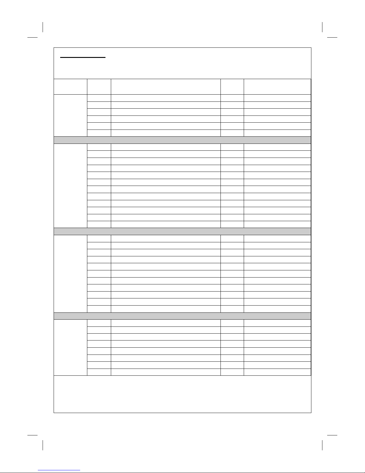
A. Parts List
Quantity varies according to model purchased. Specifications subject to change without prior notice. For
more details on hardware, please see the corresponding ‘Hardware Reference Diagram’.
Pre-Assembled Component
CODE PART QTY
Outback® Hunter
Stai nless Steel
HOOD
A1
Hood (Pre-Assembled to Body)
1
A2 Hood Handle 1
A3 Hood Hinge Pin 2
A4 R-Clip 2
A5 Heat Indicator and Nuts 1
A6 Warming Rack 1
BODY
B1 Barbecue Body 1
B2 Burner 3
B3 Contro l Pane l 1
B4 Knob 3
B5 Hose / Regulator Assembly 1
B6 Lava Rock in basket 2
B7 Large Cooking Grill 1
B8 Small Cooking Grill 1
B9 Cooking Griddle 1
B10 Drip Tray Left Bracket 1
B11 Drip Tray Right Bracket 1
B12 Drip Tray 1
TROLLEY
C1 Side Shelf 2
C2 Left Front Leg 1
C3 Left Rear Leg 1
C4 Right Front Leg 1
C5 Right Rear Leg 1
C6 Front Screen 1
C7 Leg Endcap 2
C8 Wheel 2
C9 Hubcap 2
C10 Axle 1
C11 Trolley Base 1
HARDWARE
D1 M5x15 Bolt 4
D2 Ø5 Washer 4
D3 M5 Nut 4
D4 1/4-20UNCx22 Bolt 24
D5 M6x95 Bolt 8
D6 Ø6 Spacer 8
D7 Axle Washer 2
D8 Locknut 2
Page 3
3
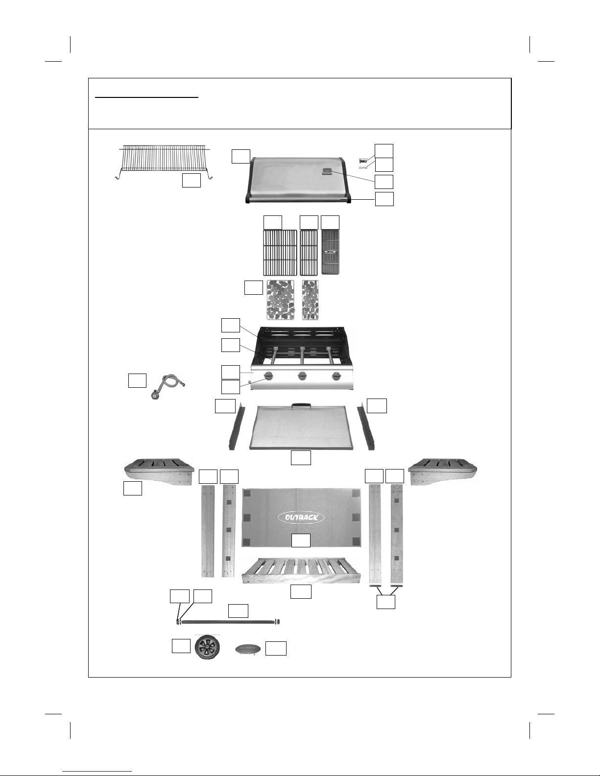
B. Parts Diagram
Quantity varies according to model purchased. Specifications subject to change without prior notice. For
more details on hardware, please see the corresponding ‘Hardware Reference Diagram’.
C1
C5
C2
C10
C8
C9
D7
C6
C11
B5
A1
A4
A3
B3
B2
B4
A5
B1
A6
B6
B7 B9
C3
C4
C7
B10
B11
B12
D8
A2
B8
Page 4
4
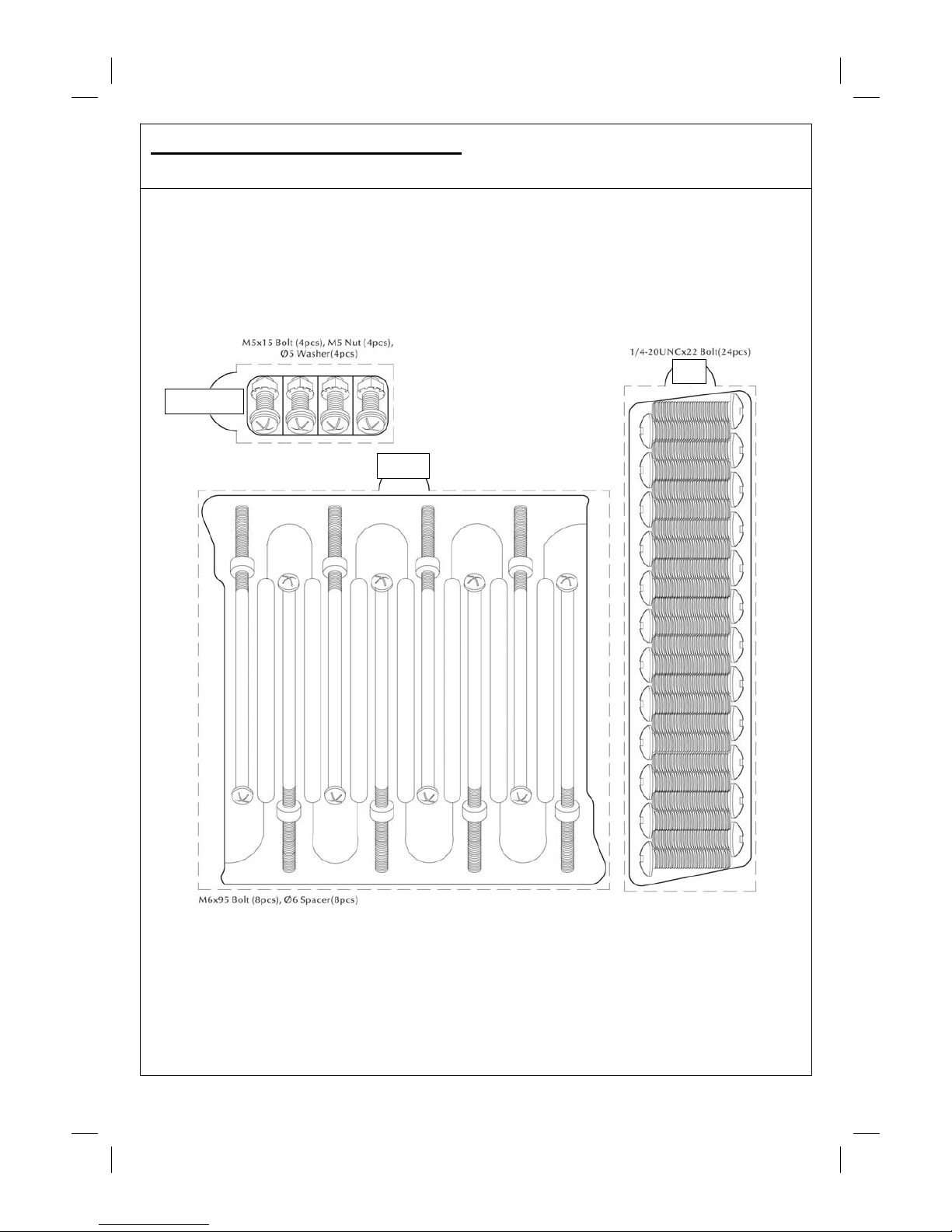
C. Hardware Reference Diagram
Specifications subject to change without prior notice.
D4
D1, D2, D3
D5, D6
Page 5
5
D. Assembly
IMPORTANT!
• TOOLS NEEDED FOR ASSEMBLY: Medium size flat blade or Phillips/Crosspoint screwdriver,
adjustable spanner or metric spanner set.
• The assembly of this barbecue requires 2 people.
• Whilst every care is taken in the manufacture of this product, care must be taken during assembly in
case sharp edges are present.
• Please read the Important Information section carefully before assembly and use of your
barbecue.
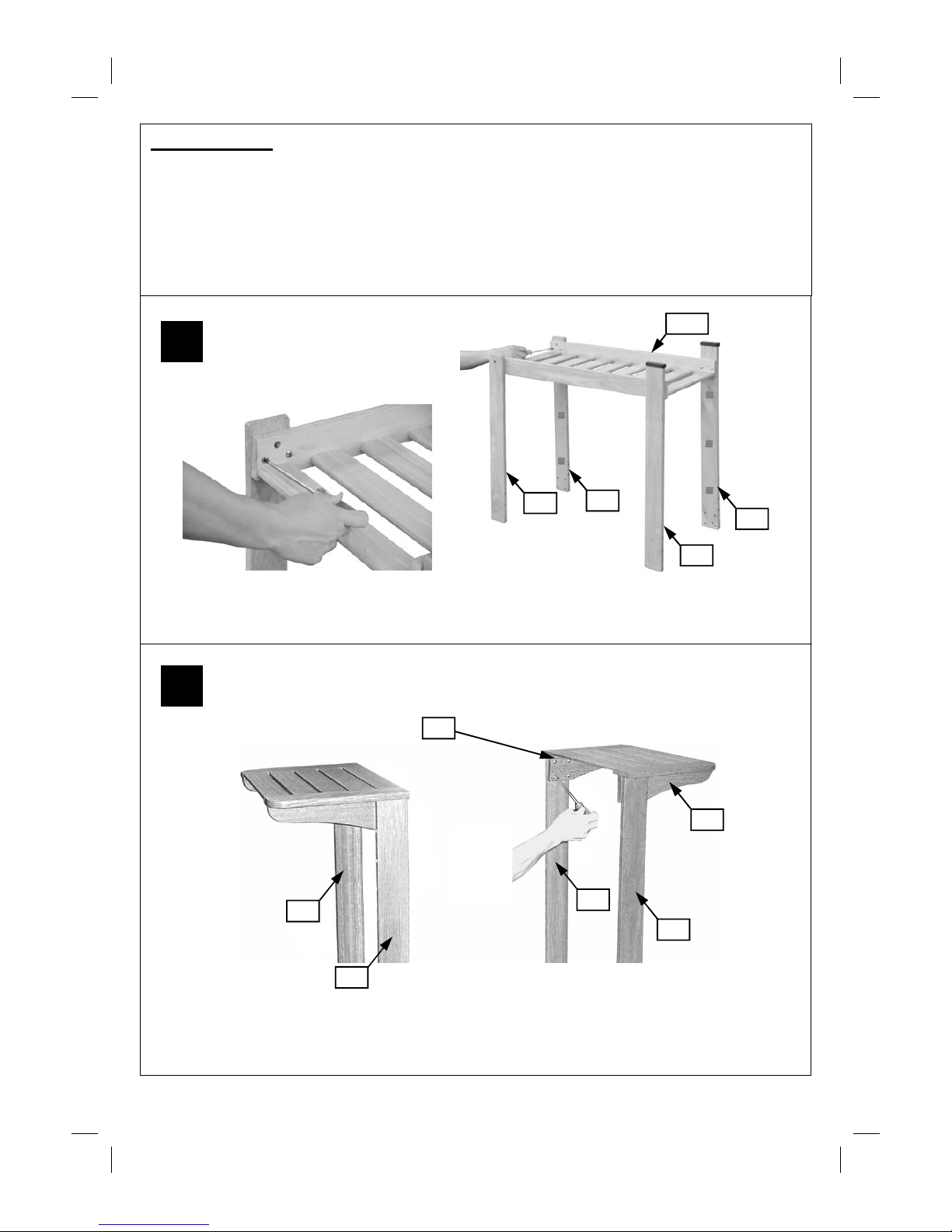
Attach the Legs (C2,C3,C4,C5) to the Trolley Base (C11) using the 1/4-20UNCx22 Bolts (D4).
Ensure that the legs with the Velcro attached to them are at the front of the barbecue, facing
inwards.
1
2
Attach the Side Shelves (C1) to the Front/Rear Left Legs (C2,C3) and Front/Rear Right
Legs (C4,C5) using the 1/4-20UNCx22 Bolts (D4).
D5
C2
C1
C4
C3
C5
(Photo depicts trolley
from the reverse side)
C3
C2
C4
C5
C11
Page 6
6
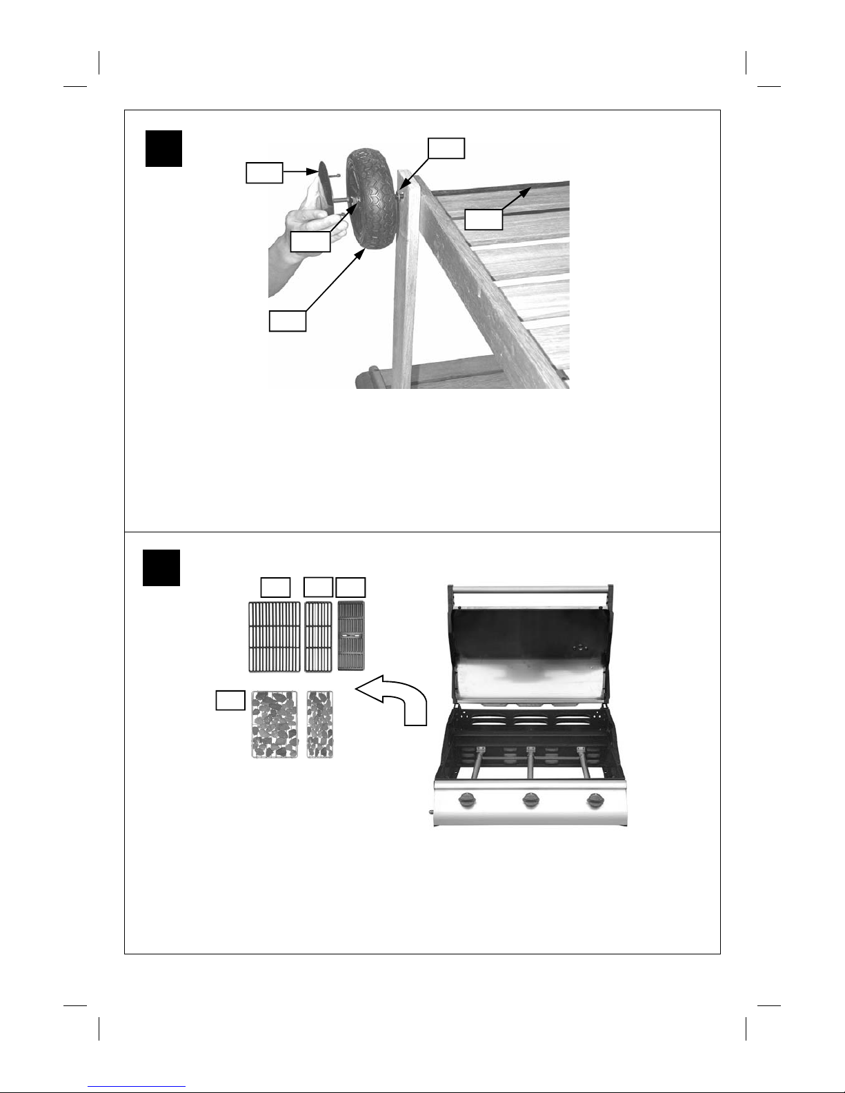
Remove all cooking components, lava rock, a nd any internal packaging from the Barbecue
Body (B1).
3
4
Turn the trolley over so that it stands on its side shelves.
Unscrew the Locknuts (D8) from both ends of the Axle (C10) and remove the Axle Washers (D7).
Slide the axle through the corresponding holes in the left l egs. Place axle was hers on each end of
the axle. Slide the Wheels (C8) over each end of the axle. Secure the wheels into place with the
locknuts. Place the wheel Hubcaps (C9) onto the outsides of the wheels.
Carefully turn the completed trolley over, right side up.
D8
C8
D7
C9
C10
B7
B8
B6
B9
Page 7

7
Lay the assembled trolley on its side. Lay the Barbecue B ody (B1) on its back and slide i nto
position between the trolley legs. CAUTION! Care must be taken to ensure the hood or lid
does not fall open unexpectedly or becomes damaged when it is set on the ground. When
positioning the body of the barbecue, ensure the control panel is on the same side as the legs
with Velcro fastenings.
With the barbecue laid on the ground, insert a M6x95 Bolt (D5) through the front left leg, through
a Spacer (D6), and screw the bolt into the sidewall of t he body completely. Repeat the process
for all the legs until the barbecue body is completely fixed to the trolley.
5
6
B1
B1
D6 D5
Page 8

8
7
8
Carefully stand the barbecue upright, taking care to ensure the hood or lid does not fall open
unexpectedly.
Attach Drip Tray Right Bracket (B11) to barbecue body using M5x15 Bolts (D1), Ø5 Washers (D2)
and M5 Nuts (D3) as shown. Repeat above process for Drip Tray Left Bracket (B10).
Insert the Drip Tray (B12) by sliding it underneath the barbecue body.
D1
D2
B12
Page 9

9
9
10
A6
Carefully lay the Lava Rock (B6) into the body ensuring it lies level within the body. Lay the Grills
(B7, B8) and Griddle (B9) into place.
3 burner model configuration: Left — Cooking Grills, Right — Cooking Griddle,
NOTE: Ensure that the lava rock lies directly underneath the grills.
Insert the Warming Rack (A6) into the hood and barbecue body. Make sure that the
swing legs fix to the body of the barbecue and the shorter fixed legs go through the holes
in the hood.
Page 10

10
11
12
Connect the gas hose to the barbecue.
Ensure the mating faces of the connection are c lean and not damaged. Do not use
any sealing tape, paste, or liquid on the connection. The nut must be tightened with
the use of a spanner. Do not use force which may damage the assembly.
(Rear view of the barbecue trolley.)
Attach the Front Screen (C6) to the front left/right legs as
C6
Page 11

11
13
ASSEMBLY IS NOW COMPLETE.
PROCEED TO THE NEXT PAGE FOR INSTRUCTIONS ON OPERATION AND
MAINTENANCE
Leak Test Diagram
ALL JOINTS AND CONNECTIONS
MUST NOW BE LEAK TESTED
BEFORE USING THE BBQ. FOR
DETAILS OF LEAK TESTING,
PLEASE REFER TO INSTRUCTIONS
ON PAGE 13.
Page 12

12
Model Butane Minimum
Bottle Size
Propane Minimum
Bottle Size
Outback®
Hunter
Stainless
Steel
15kg 10kg
E. Important Information
Please read these instructions carefully before
assembly and use.
nRetain these instructions for future reference.
nFor outdoors use only – do not use indoors.
Do not use below ground level.
nFor use with LPG bottled gas only. A fixed
pressure regulator of 28-30mbar must be used
for butane or 37mbar for propane. The use of
an adjustable regulator is dangerous and must
never be used with this barbecue.
nRemove lava rock from plastic bag before
lighting.
nDo not use within 1m of any flammable
structure or surface.
nLP gas cylinders should not be placed directly
underneath the barbecue.
nLP gas cylinders must not be stored or used in
the horizontal position. A leak would be very
serious and liquid could enter the gas line.
nWhen igniting barbecue open its hood before
lighting.
nDo not move the barbecue while alight.
nThis barbecue must not be left unattended
when lit.
nThe hood handle can become very hot. Grip
only the centre of the handle. Use of a cooking
glove is advised.
nUse caution when opening the hood, as hot
steam inside is released upon opening.
nParts of this barbecue become very hot – care
must be taken when children, elderly people,
and animals are present.
nAlways turn off the gas bottle when the
barbecue is not in use.
nNever cover a barbecue until it has completely
cooled.
nLeak test the barbecue annually. Check that
the hose connection to the barbecue is tight
and leak test whenever the gas bottle is
reconnected.
nDo not store flammable materials near this
barbecue.
nDo not use aerosols near this barbecue.
nFailure to follow the manual’s instructions
could result in serious injury or damage.
nIf you have any queries regarding these
instructions, contact your local dealer.
F. Gas and Regulator
This barbecue, hose and regulator are approved
for use in the UK. The barbecue is also approved
for use in other countries as listed on the control
panel and in the Technical Specifications included
in the barbecue manual. If the barbecue is
intended to be used outside of the UK, the
consumer MUST seek advice from the local
qualified gas supplier as to the suitability of the
barbecue and with regards to the correct hose
and regulator that they should be using.
This barbecue can use either propane or butane
LPG bottled gas. Propane bottles, normally red
coloured, will supply gas all year round, even on
cold winter days. A spanner may be
required to
change gas bottles. Butane bottles, normally blue,
will supply sufficient gas in summer, but
performance of the barbecue may be affected
once the gas tem perature starts to fall below +10°
C. The bottle should never
be stood on the trolley
base and placed directly under the barbecue. Gas
bottles should never be stored or used laid on
their side. Never store gas bottles indoors.
For optimal performance, we suggest the
following:
Suitable regulators for butane must have an outlet
pressure of 28-30mbar. For propane, the regulator
must have an outlet pressure of 37mbar. YOU
MUST HAVE THE PROPER REGULATOR AND
BOTTLE IN ORDER FOR THE BARBECUE TO
OPERATE SAFELY AND EFFICIENTLY. USE OF
AN INCORRECT OR FAULTY REGULATOR IS
DANGEROUS AND WILL INVALIDATE ANY
WARRANTY. If in doubt, please consult your gas
dealer/distributor.
G. Installation
G1. Selecting a Location
This barbecue is for outdoor use only and should
be placed in a well-ventilated area. Take care to
ensure that it is not placed UNDER any
combustible surface. The sides of the barbecue
should NEVER be closer than 1 metre from any
combustible surface. Keep this barbecue away
from any flammable materials!
G2. Precautions
Do not obstruct any ventilation openings in the
barbecue body. Position the gas supply bottle on
level ground next to the barbecue and safely away
from any source of heat. Should you need to
change the gas bottle, confirm that the barbecue
Page 13

13
is switched off, and that there are no sources of
ignition (cigarettes, open flame, sparks, etc.) near
before proceeding. Inspect the gas hose to ensure
it is free of any twisting or tension. The hose
should hang freely with no bends, folds, or kinks
that could obstruct free flow of gas. Apart from the
connection point, no part of the hose should touch
any hot barbecue parts. Always inspect the hose
for cuts, cracks, or excessive wear before use. If
the hose is damaged, it must be replaced with
hose suitable for use with LPG and meet the
national standards for the country of use. The
length of the hose shall not exceed 1.5m. N.B.-
The date on U.K. hose is the date of manufacture,
not the expiry date.
G3. Fixing the Re g ulator to the Gas Bottle
Confirm all barbecue control knobs are in the off
position. Connect the regulator to the gas bottle
according to your regulator and bottle dealer’s
instructions.
G4. Leak Testing (To be performed in a wellventilated area.)
Confirm all control knobs are in the off position.
Detach the barbecue control panel located across
the front of the barbecue body by pulling off the
control knobs and removing the control panel
retaining screws. Open the gas control valve on
the bottle or regulator. Check for leaks by
brushing a solution of ½ water and ½ soap over
all gas system joints, including all valve
connections, hose connections and regulator
connections. NEVER USE AN OPEN FLAME to
test for leaks at anytime. If bubbles form over any
of the joints, there is a leak. Turn off the gas
supply and retighten all joints. Repeat test. If
bubbles form again, do not use the barbecue.
Please contact your local dealer for assistance.
Leak test annually, and whenever the gas bottle is
removed or replaced.
H. Operation
H1. nWarnings
nBefore proceeding, make certain that you
understand the IMPORTANT INFORMATION
section of this manual.
nThis barbecue is not designed to be used with
mor e than 5 0% of th e cook ing ar ea as a so lid
plate. Full coverage of plates will cause
excessive build-up of heat and damage the
barbecue.
H2. Preparation Before Cooking
Line the drip tray with aluminium foil and fill the
drip tray with dry sand. This will absorb excess
cooking fat and make cleaning easier. To prevent
foods from sticking to the porcelain, please use a
long handled brush to apply a light coat of cooking
or vegetable oil before each barbecuing session.
H3. Lighting the Barbecue Using the IntegraSpark Integrated Ignition System
• Open the roasting hood of your barbecue
before lighting.
• Open the gas co ntrol v alve on th e gas bott le
or regulator.
• Push the control knob of the burner you wish
to light and turn it anti-clockwise until you feel
resistance to the turning. Pause 4 seconds,
then continue turning the control knob until a
click is heard and the burner is lit. If burner
does not light, turn off the gas by pushing and
holding the control knob in the “High” position
and turning to “Off”. The lighting sequence
can then be repeated 4-5 times until the
burner is lit. Ignite any of the remaining
burners in any order, as needed. Confirm
each burner is alight before igniting another
burner. If any burner fails to ignite after
following above procedure, turn all the knobs
to the off position. Close the gas valve on the
gas bottle. Wait five minutes. Reattempt all of
the above steps. If the barbecue still fails to
light, please refer to the manual ignition
instructions below.
• After ignition, turn the burners to the high
position for 3-5 minut es in order t o pre heat
the barbecue. This should be done before
each cooking session. When pre heating is
complete, cooking can begin, taking extra
care if burners are left in the high position.
H4. Manual lighting instructions
• Insert lit match through the leftmost match-
lighting hole on the right side of the control
panel and place near leftmost burner
porthole.
• Push and turn the leftmost control knob anti-
clockwise to the high position.
• Wh en t he l ef t b urn er is l it , t urn th e r em aini ng
burne rs o n from left to right.
• Confirm that each burner is alight before
turning on the next burner.
• If leftmost burner fails to light, contact your
local dealer for assistance.
• After lighting, turn the burners to the high
position for 3-5 minut es in order t o pre heat
the barbecue. This should be done before
each cooking session. When pre heating is
complete, cooking can begin, taking extra
care if burners are left in the high position.
H5. Grill Cooking
The burners heat the lava rock under the grill that,
in turn, heats the food. The natural juices
produced during cooking fall onto the flame
Page 14

14
tamers and vaporise to form smoke. The smoke
then rises and ‘bastes’ the food, giving it that
unique barbecued flavour.
When using your barbecue for grill cooking you
may wish to place the hood in the closed position
which will hol d the heat in to aid coo ki n g.
H6. Griddle Plate Cooking
The burners heat the griddle plate directly, which
then cooks the food on contact. Plates allow for
the cooking of smaller items, such as seafood,
whi c h co ul d f al l t hr o ug h th e spa c es of a gri l l. Th ey
are also suitable for cooking items that require
high-temperature/short-duration cooking, such as
vegetables and smaller cuts of fish. Similarly, it
can be used in exactly the same way as a griddle
in the kitchen, for searing steaks, cooking eggs,
etc. Alter nati vely, it can be used f or heati ng pan s
or keeping food warm.
H7. Warming Rack.
Warming racks are a convenient way to keep
cooked food warm or to warm items such as
bread rolls. Care should be taken to ensure that
any items placed on the warming rack are cooked
through and do not continue to cook and drip fat
or m eat juic es, whi ch could drip ont o the li d and
down the back of the barbecue.
H8. Roasting Hood Cooking
Barbecues equipped with a roasting hood give the
option of cooking with hood closed to form an
‘oven’ for roasting food, such as joints of meat,
whole chickens, etc.
When roasting, turn the burner directly under the
food to the OFF position. Turn all other burners to
a LOW to MEDIUM position and close the hood.
Avoid lifting the hood unnecessarily as heat is lost
every time the hood is opened. Use the
temperature gauge to check the heat of the
barbecue. DO NOT ALLOW YOUR BARBECUE
TO OVERHEAT.
H9. Rotisserie Operation Instructions (if
supplied)
1. Carefully remove the cast iron cooking
surfaces and the warming rack from the
barbecue.
2. Slide one of the spit forks onto the spit rod
and tighten its thumb screw to secure it into
place. Insert the pointed end of the spit rod
into the meat being cooked and slide the
meat towards the center of the rod. Make
sure the fork is fully into the meat. Slide the
other fork onto the rod, into the meat, and
tighten the thumb screw once in place. For
optimal rotisserie cooking, food must be
placed securely onto the middle of the spit
rod and balanced so that the rotisserie can
rotate freely without interference from any
barbecue surfaces. Any loose sections of
meat should be secured so they do not hang
down and interfere with the rotation of the spit
rod.
3. Insert the pointed end of the spit rod into the
motor. Lay the other end of the spit rod onto
the opposite bracket.
4. Light the grill as specified in your barbecue’s
instructions.
5. Turn on the rotisserie motor to begin
rotisserie cooking. The hood has been
designed so that it may be closed during
rotisserie cooking.
6. Always cook foods on the lowest flame
setting to avoid burning or overcooking.
H10. Flare-Up Control
Flare-ups occur when meat is barbecued, and its
fat and juices fall upon the hot flame tamers.
Smoke helps give food its barbecued flavour, but
avoid excessive flare-up to prevent food being
burned. To control flare-up, it is advisable to trim
away excess fat from meat and poultry before
grilling. To reduce flare-ups, the burners should
be turned down to the low setting. Fl are–ups can
be extinguished by applying baking soda or salt
directly onto the flame tamers. Always protect
your hands when handling anything near the
coo king sur face o f the bar becue. Flare- ups oc cur
more at the start of cooking, particularly with
processed meat products, and it may be
necessary to turn the burners down to their lowest
setting to start with and then turning up at a later
stage in the cooking process. The barbecue
should also not be overloaded. Some parts of the
cooking area are hotter than others. The hottest
areas will be above the burners which will be
wher e the f la re up s will norm all y star t. By leavi ng
free space you can simply move the food away
fr om th e f la r e u p t o a c oo l er ar ea un ti l t h e fl a r e u p
has subsided.
If a fat fire should occur in the drip tray, turn all
knobs to the off position, turn off the gas at the
bottle, and wait for the fire to go out. Do not pull
out the drip tray or dou se wit h w ater.
H11. End of Cook ing Se ssion
After each cooking session, turn the barbecue
burners to the “high” position and burn for 5
minutes. This procedure will burn off cooking
residue, thus making cleaning easier. Make sure
the hood or lid is open during this process.
H12. Turning Off Your Barbecue
Wh en you ha ve finished using your b arbecue, turn
all the control valves fully clockwise to the “Off”
position. To do this, push and hold in the control
Page 15

15
knob at the “High” position and turn to “Off”. The
gas must then be turned o ff at the bottle.
I. Care and Maintenance
Regularly clean your barbecue between uses and
especially after extended periods of storage.
Ensure the barbecue and its components are
sufficiently cool before cleaning. Do not leave the
barbecue exposed to outside weather conditions
or stored in damp, moist areas.
nNever douse the barbecue with water when its
surfaces are ho t .
nNever handle hot parts with unprotected
hands.
In order to extend the life and maintain the
condition of your barbecue, we strongly
recommend that the unit be covered when left
outside for any length of time, especially during
the winter months. Heavy-duty Outback®
barbecue covers and other accessories are
available from your local Outback® stockist.
Even when your barbecue is covered for its
protection, it must be inspected on a regular basis
as damp or condensation can form which may
result in damage to the barbecue. It may be
necessary to dry the barbecue and the inside of
the cover. Any rust that is found that does not
come into contact with the food should be treated
with a rust inhibitor and painted with barbecue
paint or a heat resistant paint. Wooden parts may
also need to be cleaned and re oiled. Chrome
plat ed warmin g rac ks etc. shoul d be coated with
cooking oil.
I1. Cooking Surfaces
Clean with hot, soapy water. To remove any food
residue, use a mild cream cleaner on a nonabrasive pad. Rinse well and dry thoroughly. W e
do n ot recom mend cleaning grills and griddles in a
dishwasher.
I2. Burner Maintenance
Provided that they are operating correctly, in
normal usage, burning off the residue after
cooking will keep the burners clean. The burners
should be removed and cleaned annually, or
whenever heavy build up is found, to ensure that
there are no signs of blockage (fat, debris or
insects for example) , in either t he bur ner porthol es
or the burner primary air inlet. Use a pipe cleaner
to cl ear obst ructions. When refitti ng the burners,
be careful to check that the neck of the burner fits
over the va lve out let.
Your burners have been preset for optimal flame
performance. You will normally see a blue flame,
possibly with a small yellow tip when the burner is
alight. If the flame pattern is significantly yellow,
this could be a problem caused by grease from
cooking blocking the burner or spiders or other
insects in the burner venturi. This can result in the
flow of the gas and air mixture being restricted or
blocked which may result in a fire behind the
control panel causing serious damage to your
barbecue. If this happens, the gas should be
immediately turned off at the bottle. Burners
should be inspected and cleaned on a regular
basis in addition to the following conditions:
• Bringing the barbecue out of storage.
• One o r m ore of the bur ners do not ign ite.
• The burner flame pattern is significantly
yellow.
• The gas ignites behind the control panel.
To clean a burner, remove it from the barbecue.
The outside of the burner can be cleaned with a
wire brush.
Clean the portholes with a pipe cleaner or piece of
wire. Take care not to enlarge the portholes.
Clean the insect screen on the end of the venturi
tube with a bristle brush (i.e. an old toothbrush).
Clean the venturi tube with a pipe cleaner or piece
of wire. You may need a torch to see into the
venturi tube to make sure it is clear.
Turn the burner up on end and lightly tap against
a piece of wood to dislodge any debris from
inside.
I3. Lave Rock
It is not necessary to remove and wash the lava
rock in order to keep it clean. Burning off the
residue for 3 to 5 minutes after each cooking
session should be sufficient. Heavily impregnated
lava rock should be turned over so that the dirty
side faces the burners in order to burn off any
1
2
3
4
Page 16

16
residue. Replacement lava rock is available from
your local Outback® stock ist.
I4. Drip Tray
Aft er ev er y use, chec k t h e dri p tr ay f or fat b uil d u p
in the sand. Discard any saturated sand and
replace it with fresh sand. Failure to carry out this
procedure can result in a fat fire in the tray. This
can severely damage the barbecue and is not
covered by the warranty. If the barbecue is being
used for extended periods the burners should be
turned off and the drip tray checked before the
end of the cooking session.
I5. Barbecue Body
Regularly remove excess grease or fat from the
barbecue body with a soft plastic or wooden
scraper. It is not necessary to remove all the
grease from the body. If you need to clean fully,
use hot soapy water and a cloth, or nylon-bristled
brush only. Remove cooking surfaces and burners
before full cleaning. Do not immerse the gas
controls or manifold in water. Check burner
operation after carefully refitting into body.
I6. Barbecue Hood
Use a non-abrasive cloth or pad and clean with
hot, soapy water. Do not use scouring pads or
powders as they can permanently damage the
finish. The inside of the hood will also need
cleaning to prevent an excess build up of grease
which can then turn to carbon and start to flake
off. This can resemble paint flaking off but it is not
as the hood is porcelain coated.
I7. LPG Hose
The LPG hose does not have a time-limited inservice life but it is essential that the hose and
end connections are regularly inspected and
replaced if showing signs of:
• Physical damage such as – cuts or abrasion,
cracking, stretching, flattening or kinking;
• Environmental deterioration such as –
stiffening, cracking, de-lamination of outer
covering, chemical degradation i.e. softening
of outer coati ng by con tact with oil;
• Hose service failure such as – blistering, soft
spots, rupture or corrosion or loosening of the
swaged fittings or worm drive clips attaching
the hose.
I8. Trolley
Your trolley is manufactured using a hardwood
suit ed to out door use, provided it is trea ted with
Teak oi l or si m ilar aft er as s em bl y a nd on a reg u l ar
basis thereafter. Hardwood will naturally weather
and change its appearance. It is quite natural for
small cracks to appear on the surface of the
wood.
I9. Fixings
All screws and bolts, etc. should be checked and
tightened on a regular basis.
I10. Storage
Store your barbecue in a cool dry place. It must
be inspected on a regular basis as damp or
condensation can form which may result in
damage to the barbecue. It may be necessary to
dry the barbecue and the inside of the cover if
used. Mould can grow under these conditions and
should be cleaned and treated if required. Any
rust that is found that does not come into contact
with the food should be treated with a rust inhibitor
and painted with barbecue paint or a heat
resistant paint. Wooden parts may also need to be
cleaned and re oiled. Chrome plated warming
racks etc. should be coated with cooking oil. Wrap
the burners in aluminium foil to help prevent
insects or other debris from obstructing the
burners.
The gas bottle must be always be disconnected
fr om the bar becue an d stored in a well ven tilat ed
area at least 1 metre away from any fixed ignition
source. Do not store inside residential
accommodation. Never store cylinders below
ground level (e.g. cellars). Do not let children
tamper with bottles.
J. Technical Specifications
Specifications are subject to change without prior notice.
CE
Approval
Heat
Input
Burners
Injector
Size
Gas /Pressure
Outback®
Hunter
Stainless
Steel
0359
359BR665
11.88
kW
3
1.05mm
1.05mm
0.99mm
0.91mm
Butane: 28-30 mbar
Propane: 37 mbar
LPG mixture: 30 mbar
LPG mixture: 37 mbar
LPG mixture: 50 mbar
Gas Consumption:
Hunter Stainless Steel: 855g/hr
Countries of Use:
I
3+ (28-30/37)
BE, CH, CY, CZ, ES, FR, GB, GR, IE, IT, LT, LU, LV, PT, SK,
SI
I
3B/P(30)
BE, CY, DK, EE, FI, FR, HU, IT, LT, NL, NO, SE, SI, SK, RO,
HR, TR , B G , IS, LU, MT
I
3B/P(37)
PL
I
3B/P(50)
AT, CH, DE, SK
Page 17

17
K. Troubleshooting
Problem Possible Cause Solution
Burners will not light using
the ignition sys tem
LP gas bottle is empty Replace with full bottle
Faulty regulator Have regulator checked or re place
Obstructions in burners Clean burne rs
Obstructions in gas jets or gas hose Clean jets and gas hose
Electrode wire is loose or disconne cted
on electrode or ignition unit
Reconnect wire
Electrode or wire is da mage d Change electrode and wire
Faulty in tegral ignitor Change ignitor
Burner will not light with a
match
LP gas bottle is empty Replace with full bottle
Faulty regulator Have regulator checked or re place
Obstructions in burners Clean burne rs
Obstructions in gas jets or gas hose Clean jets and gas hose
Low flame or flas hback
(fire in burner tube— a
hissin g or roar in g noise
may be heard)
LP gas bottle too small Use larger bottle
Obstructions in burners Clean burne rs
Obstructions in gas jets or gas hose Clean jets and gas hose
Windy conditions Use BBQ in a mo re sheltered position
Gas valve knob difficult to
turn
Integral ignition syste m jammed Replace gas valve
Gas valve jammed Replace gas valve
For reference and c orrespondence,
record your serial number here.
(See sticker on side of barbecue body.)
Serial No.__________________
This number may be required when
ordering spare parts or acc es sories. A
part reference num ber may also be
required where appli c able.
Page 18

18
OUTBACK UK LTD
WARRANTY
OUTBACK barbecues are warrant ed to t he ori ginal purchaser again st def ects i n materi als and
workmanship f or a period of one (1) year from the date of purchase. O UTBACK UK will, within
this period, supply r eplacements for defectiv e parts fr ee of char ge pr ov ided that:
♦ The produc t has not been used for trade, prof essional or hire purposes.
♦ The produc t has not been subjected to misuse or neglect, including fat fires and fl ar e ups
or use of a faulty or incorr ec t regulator.
♦ The produc t has not sustained damage through foreign objects, substances or accidents.
♦ The car e and maintenance instructi ons given in your Outback manual have been followed.
This warranty is offered as an extra benefit and is in addition t o the custom ers’ statutory rights.
Outback UK does not warranty in any way the gas cylinder.
If you have any queries regarding the assembly or use of your barbecue please contact
Outback UK
In t he unli kely event that you experience
problems with this barbeque, please contact:
website: www.outbackbarbecues.com
 Loading...