

Outback Mayfair, Tungsten, SE, Spirit, Titanium Assembly Manual
...
Elite Series Barbecues
Assembly and Operating In str u ctions for Outback® Mayfair/Tungsten,
Outb ack® Spi rit/ Titanium, and Outb ack® Performance/Platinum Hood ed Gas Barb ecu es
0359
Photographs are not to scale.
Specifications subj ect to change
without prior notice.
WARNING
• For outdoor use only.
• Rea d ins truc tio ns bef ore us ing the appl ia nc e. Failu re to fol low i ns t ructions
could result in death, serious bodily injury, and/or property loss.
• Warni ng: accessible parts may be ve ry hot . Keep young c hildren away.
• D o not mo v e th e a pplia nc e du ring us e .
• Turn off the gas supply at the gas bottle after use.
• Any modification of the appliance, misuse, or failure to follow the instructions
may be dangerous and will invalidate your warranty. This does not affect your
statutory rights.
• Retai n these instruction s for future r efer ence.
•
Leak test your barbecu e annu all y. Ch eck the hose connection s ar e tig h t and leak
test each time you reconn ect the g as bo ttle.
FOR YO UR SA FETY
If you smell gas:
1. Shut off gas to the appliance.
2. Extin guish any op en flame.
3. Open barbecue lid or hood.
4. If odour continues, discontinue use and
contact y our loca l deale r.
FOR YO UR SA FETY
1. Do not store or use petrol or other flammable
vapours or liquids in the vicinity of this or any
other appliance.
2. A gas bottle not connected for use shall not be
stored in the vicinity of this or any other
appliance.

2
Part s Li st
Quantit ies vary acc ording to model purc hased. Specif ic ations subject to change without prior not ic e. For more
details on hardware, please see ‘Hardware Ref erenc e Diagram’.
Pre-Assembl ed Component
Quan ti t y var i es ac c or ding to model pur c h as e d
Appear ance, size, and construc tion may differ acc ording to model purchased
Outback® Ti t a ni u m/Pl a t i nu m, th es e t w o mod el s were ap pr ove d b y T UV
CODE PART QTY
Mayfair/
Tungsten
Spirit/
Titanium
Performance/
Platinum
HOOD
A1 Hood Handl e 1
A2 L/H Hood Handle Bracket 1
A3 R/H Hood H andl e Brac ket 1
A4
Hood (Pre-Ass embled to Body)
1
A5 H ood Pa nel 1
A6 Heat Indicator and Nuts 1
BODY
B1 Bar becue Bo dy 1
B2 Burner 2 3 6
B3 Burner Clip 2 3 6
B4 Co nt rol Panel 1
B5 Knob 2 3 6
B6 Drip T ray 1
B7 Drip Pan 1
B8 Foil Liner 1
B9 Lava Rock Basket 2
B10
Lava Rock Pack (in Bask et )
2
B11 Grill 2
B12 Griddle 1
B13 Hose 1
B14 Warmi ng Rack 1
TROLLE Y
C1 L/H Side Shelf 1
C2 Si de Shel f Shi el d 1
C3 Front Left Endcap 1
C4 Rear Left Endc ap 1
C5 Utensil Tray 2
C6 R/H Side Shelf 1
C7 R/H Insert 1
C8 Front Left Leg 1
C9 Rear Left Leg 1
C10 Fr on t Right Leg 1
C11 Rear Right Leg 1
C12 Bottom Slat Assembly 1
C13 Base Tray 1
C14 Gas Bottle Holder 1
C15 Trolley Foot 1
C16 Hubcap 2
C17 Wheel 2
C18 Locknut 2
C19 Ax le 1
C20 Re ta ining Rod 1
C21 Gas Bottle Strap 1
HARDWARE
D1 Countersunk Screw, M4x15 4
D2 Screw, M6x15 24
D3 Washer 4
D4 Screw, M6x35 16

3
Part s Diag rams
Quantit ies vary acc ording to model purc hased. Specif ic ations subject to change without prior not ic e. For more
details on hardware, please see ‘Hardware Ref erenc e Diagram.’
B10
B9
A1
B3 C2
B4
B5
B6
B2
C3
C5 C4 C1
B8
C6
B7
A4
A2 A3
C12
B12
B14
B13
B11
C15
C14
C16
C17
C18
C19
C9
C8
C11
C21
C20
C7
C10
A6
A5
B1
C13
4
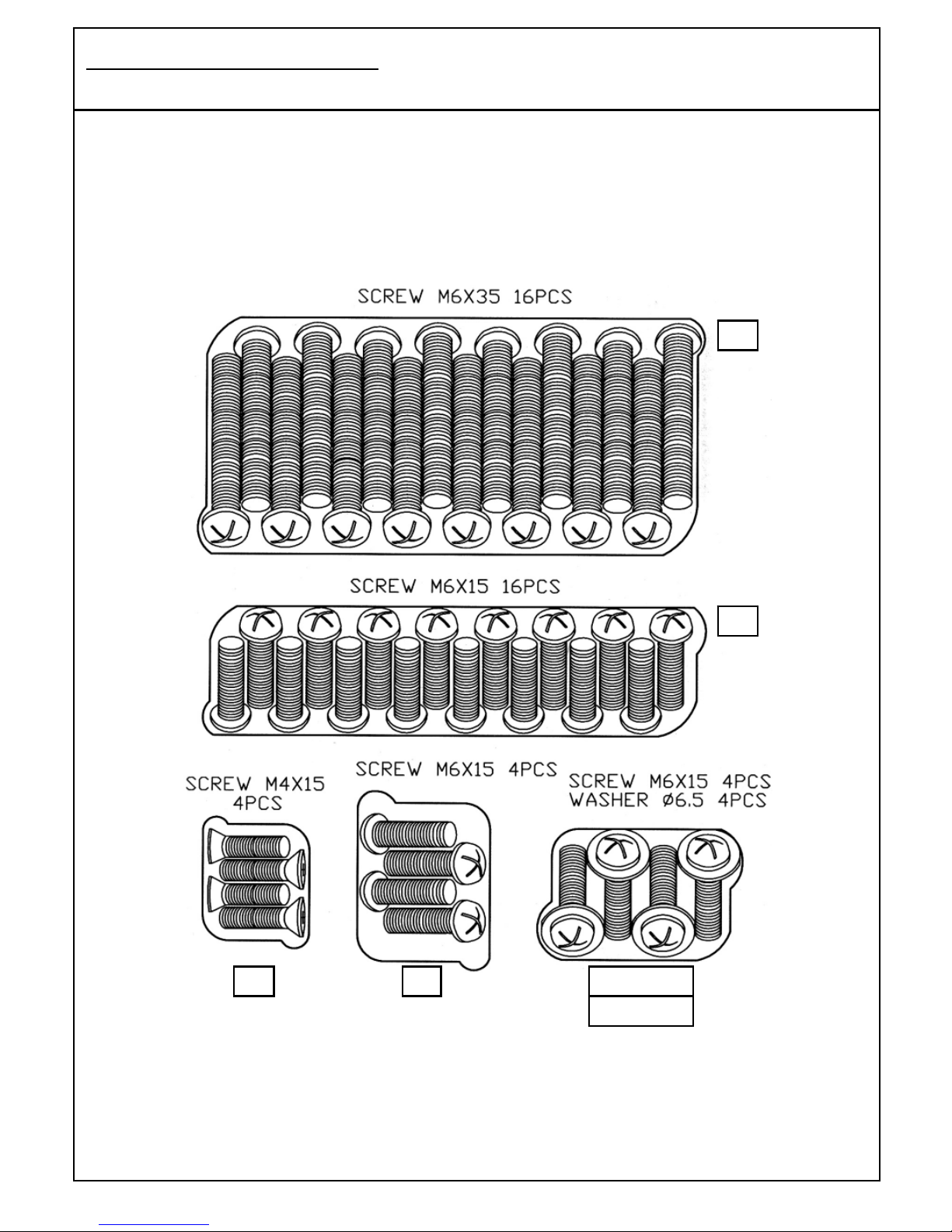
Hardware Reference Diagram
Specif ic ations subject to change without prior notic e.
D1
D2
D2 (s crew)
D3(washer)
D2
D4
5
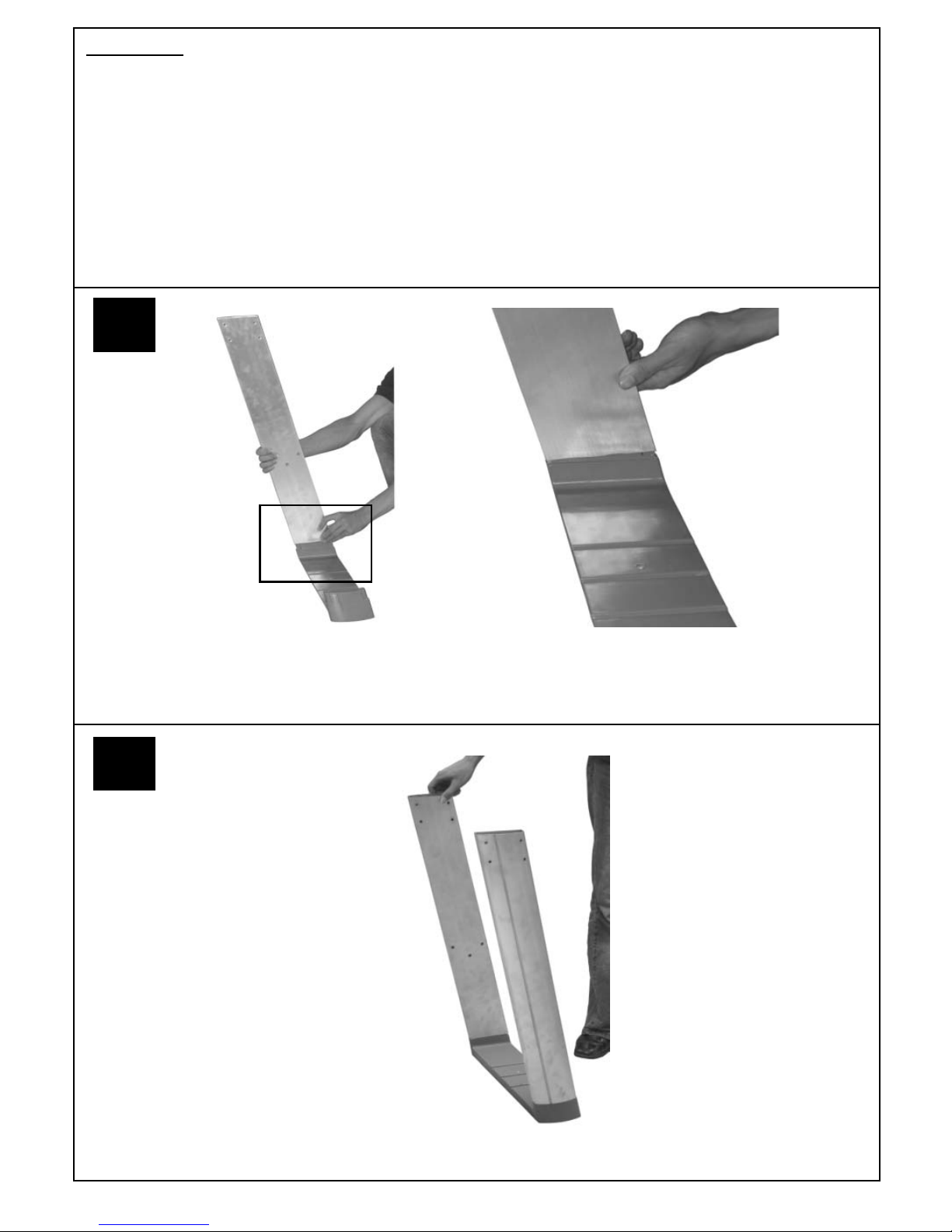
Attach the Front Right Leg (C10) to the Trolley Foot (C15)
Assembly
IMPORTANT!
•
Tools Required: Medium size flat blade or Phillips/Crosspoint screwdriver, adjustable spanner or metric
spanner s et
•
The assem bly of t his barbecue requires 2 people.
•
Caref ully unpack the trolley box and rem ove all internal pac k aging before comm encing ass embly .
•
Caref ully remove the box lid from the body box and remov e all internal packaging and parts inside the body.
•
The inlet connection of t he gas rail as s embly on the BBQ body is lower than the body. Y ou m ust never allow
the pipe to rest on t he ground during as s embly as serious dam age could res ult. We recommend the body is
left sitting in the box until required for assembly to trolley.
•
Whilst ev ery care is taken in the manufacture of this product, care must be taken during assembly in case
sharp edges are present.
1
Att ac h the Rear R ight Leg (C11) to the Trolley Foot (C15). The legs are a push fit ont o the t rolley foot and on
the gas bottle holder. In cas e of diff ic ulty, they may need tapping light ly with a soft f ace mallet. Take care not to
damage parts.
2
6
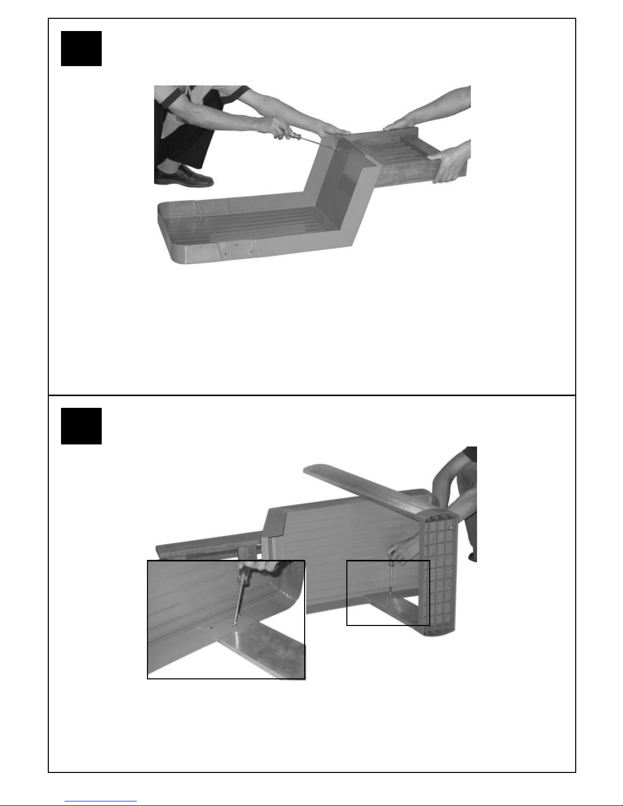
Attach the Bottom Slat Assembly (C12) to the Base Tray (C13) using the Screws (D2).
Attach the leg assembly to the Base Tray (C13) using the Screws (D2).
4
3
7
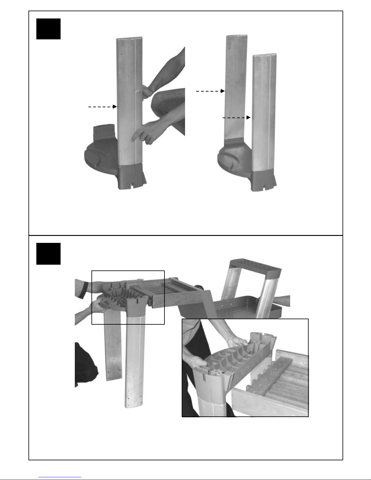
Align the Gas Bottle Holder (C14) with the Slat Assembly (C12).
Attach the Front Left Leg (C8) and Rear Left Leg (C9) to the Gas Bottle Holder (C14).
Threaded
Insert
6
5

8
Attach the Gas Bottle Holder (C14) to the Bottom Slat Assembly (C12) using the Screws (D2)
and Was hers (D3).
Ins ert the axle (C19) through the clam ping brack ets on t he gas bottle holder (C 14) and tighten the clam p
sc rews. Take care not to over t ight en these sc rews which will dam age the plastic Gas Bot t le Holder.
8
7
 Loading...