

Page 1

Elite Series Barbec ues
Assembly and Operating Instructions for Outback®
Sapphire 2 Burner, 3 Burner, 6 Burner Stainless Gas Barbecues
Photographs are not to scale.
Specifications subject to change
without prior notice.
WARNING
• For outdoor use only.
• Read instructions before using the appliance. Failure to follow instructions
could result in death, serious bodily injury, and/or property loss.
• Warning: accessible parts may be very hot. Keep young children away.
• Do not move the appliance during use.
• Turn off the gas supply at the gas bottle after use.
• Any modification of the appliance, misuse, or failure to follow the instructions
may be dangerous and will invalidate your warranty. This does not affect your
statutory rights.
• Retain these instructions for future reference.
• Leak test your barbecue annually. Check the hose connections are tight and
leak test each time you reconnect the gas bottle.
FOR YOUR SAFETY
If you smell gas:
1. Shut off gas to the appliance.
2. Extinguish any open flame.
3. Open barbecue lid or hood.
4. If odour continues, discontinue use and
contact your local dealer.
FOR YOUR SAFETY
1. Do not store or use petrol or other flammable
vapours or liquids in the vicinity of this or any
other appliance.
2. A gas bottle not connected for use shall not be
stored in the vicinity of this or any other
appliance.
0359
Page 2
2
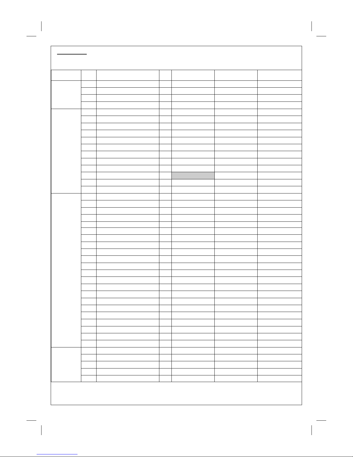
Parts List
Quantities vary according to model purchased. Specifications subject to change without prior notice. For more
details on hardware, pl ease see ‘Hardware Reference Diagram’.
Pre-Assembled Component
Quantit y varies acc ording to mod el pur c h as ed
Appearance, si z e, an d c ons truction m ay differ according to model purchased
CODE PART QTY
Outback® Sapph ire
2 Burner
Outback® Sapph ire
3 Burner
Outback® Sapph ire
6 Burner
HOOD
A1 Hood Handle 1
A2
Hood (Pre-Assembled to Body)
1
A3 Hood Panel 1
A4 Heat Indicator and Nuts 1
BODY
B1 Barbecue Body 1
B2 Burner
2 3 6
B3 Contro l Panel 1
B4 Knob
2 3 6
B5 Drip Tray 1
B6 Drip Pan 1
B7 Foil Liner 1
B8 Flame Tamer
2 2 4
B9 Grill 2
B10 Griddle 1
B11 Hose 1
B12 Warming Basket 1
TROLLEY
C1 L/H Side Shelf 1
C2 Side Shelf Shield 1
C3 Front Left Endcap 1
C4 Rear Left Endc ap 1
C5 Utensil Tray 2
C6 R/H Side Shelf 1
C7 R/H Insert 1
C8 Front Left Leg 1
C9 Rear Left Leg 1
C10 Front Right Leg 1
C11 Rear Ri ght Leg 1
C12 Bottom Slat Assembly 1
C13 Base Tray 1
C14 Gas Bottle Holder 1
C15 Trolley Foot 1
C16 Hubcap 2
C17 Wheel 2
C18 Locknut 2
C19 Axle 1
C20 Retaining Rod 1
C22 Side Shelf Hook 2
HARDWARE
D1 Countersunk Screw, M4x15 4
D2 Screw, M6x15 24
D3 Washer 4
D5 Screw, 1/4UN Cx12 6
C21 Gas Bottle Strap 1
D4 Screw, M6x35 16
Page 3
3
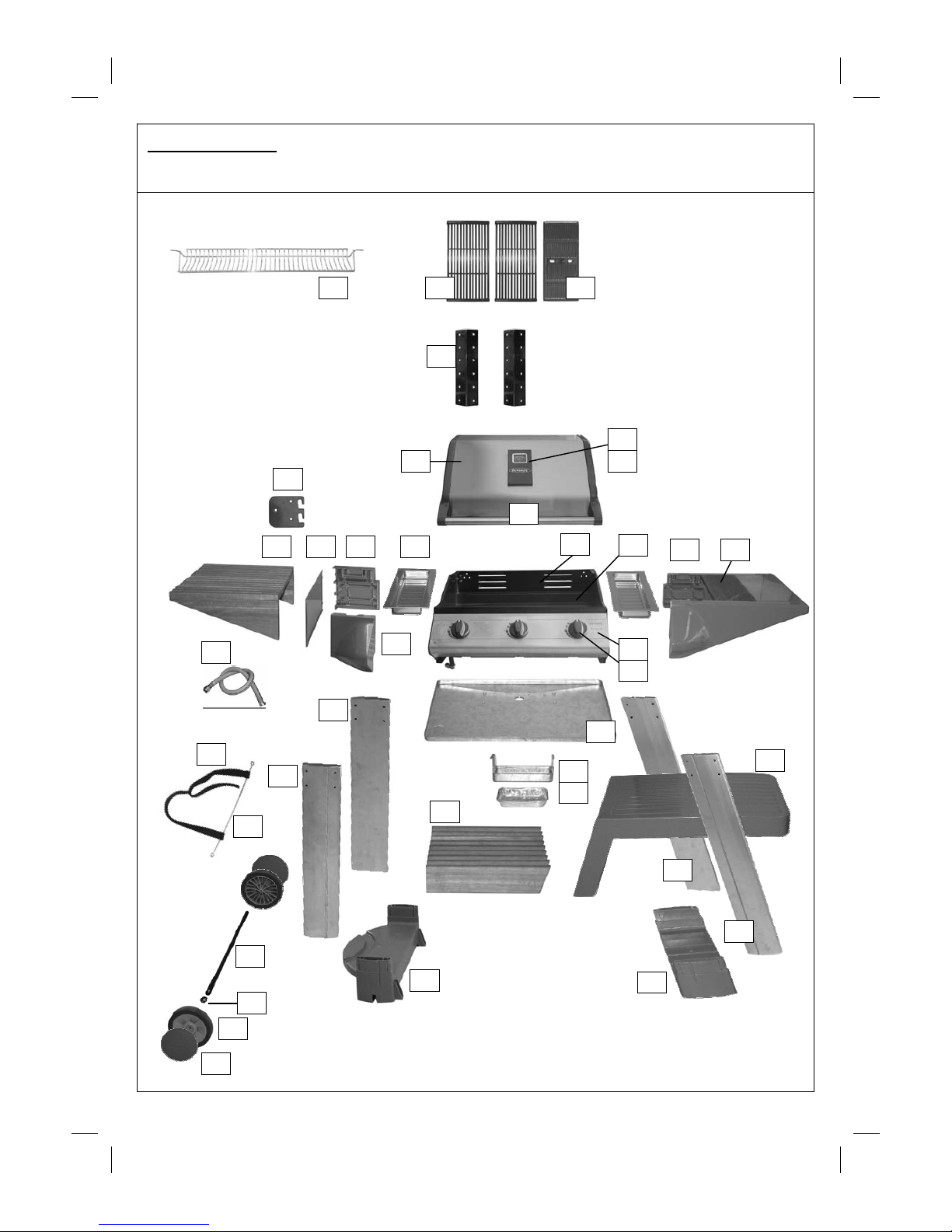
Parts Diagrams
Quantities vary according to model purchased. Specifications subject to change without prior notice. For more
details on hardware, pl ease see ‘Hardware Reference Diagram.’
B8
A1
C2
B3
B4
B5
B2
C3
C5 C4 C1
B7
C6
B6
A2
C12
B10
B11
B9
C15
C14
C16
C17
C18
C19
C9
C8
C11
C21
C20
C7
C10
A4
A3
B1
B12
C13
C22
Page 4
4
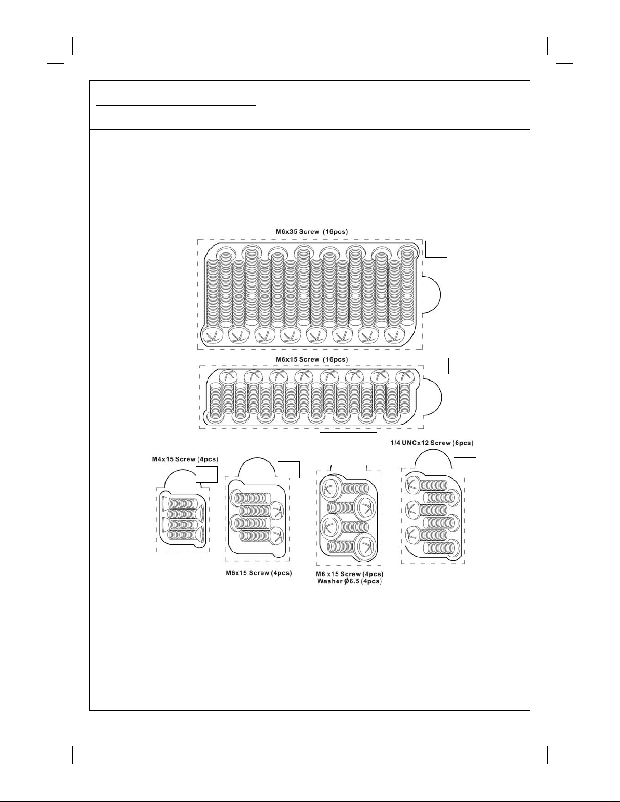
Hardware Refe rence Diagram
Specifications subject to change without prior notice.
D1
D2
D2 (screw)
D3(washer)
D2
D4
D5
Page 5
5
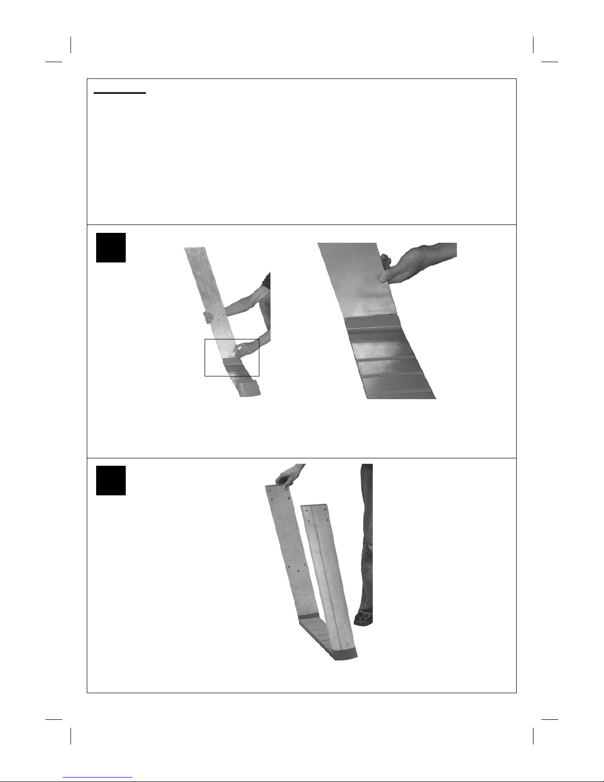
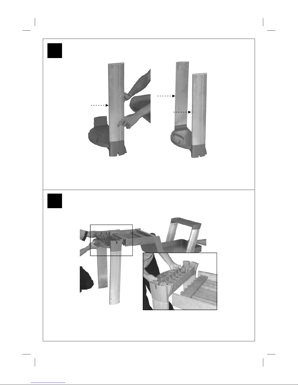
Attach the Front Right Leg (C10) to the Trolley Foot (C15)
Assembly
IMPORTANT!
• Tools Required: Medium size flat blade or Phillips/Crosspoint screwdriver, adjustable spanner or metric
spanner set
• The assembly of this barbecue requires 2 people.
• Carefully unpack the parts from the box and remove all internal packaging before commencing assembly. All
loose items including the grills, griddle, flame tamers and warming basket must be removed from the body.
• The inlet connection of the gas rail assembly on the BBQ body is lower than the body. You must never allow
the pipe to rest on the ground during assembly as serious damage could result. We recommend the body is
left sitting in the box until required for assembly to trolley.
• Whilst every care is taken in the manufacture of this product, care must be taken during assembly in case
sharp edges are present.
2
Attach the Rear Right Leg (C11) to the Trolley Foot (C15). The legs are a push fi t onto the trolley foot and
on the gas bottle holder. In case of difficulty, they may need tapping lightly with a sof t face m allet. Take
care not to damage parts.
1
Page 6

6
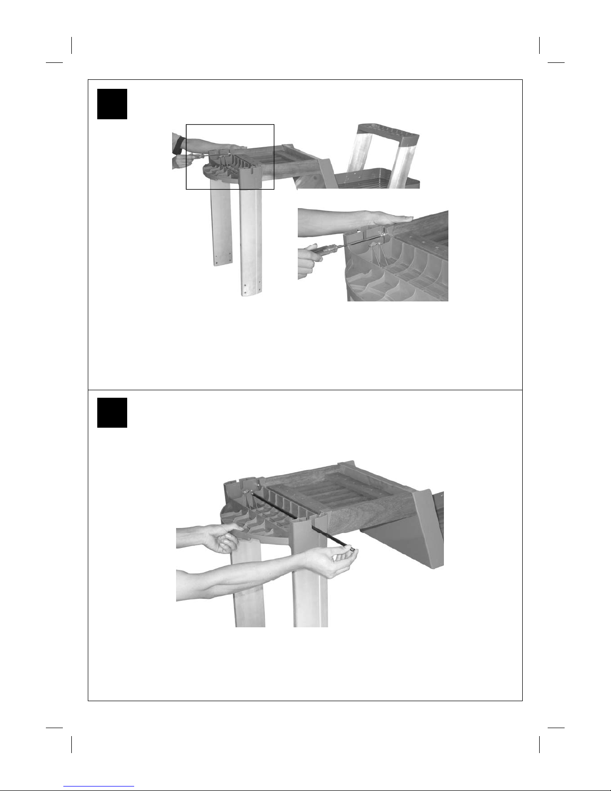
Attach the Bottom Slat Assembly (C12) to the Base Tray (C13) using the Screws (D2).
Attach the leg assembly to the Base Tray (C13) using the Screws (D2).
4
3
Page 7
7
Align the Gas Bottle Holder (C14) with the Slat Assembly (C12).
Attach the Front Left Leg (C8) and Rear Left Leg (C9) to the Gas Bottle Holder (C14).
Note: Threaded inserts must be facing in the direction shown!
Threaded
Insert
6
5
Page 8
8
Attach th e Gas Bottle Ho ld er (C14) to the Bottom Slat Assembly (C12) u sing the Scre w s
(D2) and Washers (D3).
Insert the axle (C19) through the clamping brackets on the gas bottle holder (C14) and tighten the clamp
screws. Take care not to over ti ghten these screws which will damage the plastic Gas Bottle Holder
8
7
Attach the Gas Bottle Holder (C14) to the Bottom Slat Assembly (C12) using the Screws (D2)
and Washers (D3).
Page 9

9
Place the Wheels (C17) onto the Axle (C19) and secure with Locknuts (C18).
Carefully turn the completed trolley over, right side up.
10
9
Page 10

10
CAUTION! Care must be taken to ensure hood does not fall open
unexpectedly or that the hood surface is damaged when set on the ground.
Carefully turn the Bar becue Body (B1) upside down and remove the Drip Tray (B5). Attach the
R/H Side Shelf (C6) to the Barbecue Body (B1) using the Screws (D2).
Attach the Front Left Endcap (C3) to the Body (B1) using the Screws (D2).
12
11
Page 11

11
Attach the Rear Left Endcap (C4) to the Body (B1) using the Screws (D2).
CAUTION! Care must be taken to ensure hood does not fall open unexpectedly.
Carefully turn the Bar becue Body (B1) over right-side-up.
14
13
Page 12

12
Carefully lay the Barbecue Body (B1) onto the tops of the legs. The tops of the legs should slot into the
endcaps. When done correctly, the barbecue should be able to stand on its own weight.
WARNING: DO NOT RELEASE THE BARBECUE BODY WHILE THE BARBECUE HAS NOT BEEN
PROPERLY SEATED. THIS MAY RESULT IN INJURY OR DAMAGE TO YOUR BARBECUE.
Secure the Legs (C8), (C9), (C10), (C11) to the Endcaps (C3), (C4) and the R/H
Side Shelf (C 6) using the Screws (D4).
16
15
Page 13

13
Attach the Side Shelf Shield (C2) to the endcaps using the Countersunk Screws (D1).
Attach the Side Shelf Hook (C22) to the L/H Side Shelf (C1) using the Screws (D5),
Hook the side shelf to the endcaps.
18
17
Page 14

14
Lay the Utensil Trays (C5) into their positions on either side of the barbecue body.
Place the Wheel Hubc aps (C16) onto the sides of the Wheel s (C17)
20
19
Page 15

15
Slide the loops of the Gas Bottle Strap (C21) onto the Retaining Rod (C20). Secure
the Rod (C20) to the trolley legs using the Screws (D2).
Ensure the strap is threaded through the buckle correctly. It must hold the gas bottle
firmly in place onto the barbecue.
Slide the Drip Tray (B5) into place under neath the barbecue body.
22
21
Page 16

16
Place the Foil Liner (B7) into the Drip Pan (B6) and slide into place.
Remove the plastic wrap from the Flame Tamer (B8) and lay them carefully into the body ensuring
that they lie level within the body. Lay the Grills (B9) and Griddle (B10) into place.
2 Bur ner Configuration: Left half - Grill, F lame Tamer ; Right hal f - Grill, Flame Tamer ;
3/6 Burner Con figuration: Left two-t hirds - Grills, Flame Tamer; Right third - Grid dle;
24
23
Page 17

17
Connect the gas hose (B11) to the BBQ. Ensure the mating faces of the connection are clean and not
damaged. Do not use any sealing tape, paste, or liquid on the joint. The nut must be tightened with the
use of a spanner. Do not use force which may damage the assembly.
Asse m b ly is now comp lete.
All joints and connections must now be leak tested before using the barbecue.
For details of leak testing, please refer to instructions on Page 20.
Num ber of valv es to b e l eak t ested wi ll vary with mod el of barbecue.
26
25
Page 18

18
nESSENTIAL INFORMATION
Please read instructions before using your barbecue.
BEFORE YOU USE YOUR BARBECUE (also see installation)
• Perform a leak test. This is the only safe and sure way to detect any gas leaking from joints and
connections of the bar becue after assem bly. Follow the leak test instructions on page 20. Check that the
gas hose is free of any tension, twisting, cuts, or cracks.
• Make sure your barbecue is in a safe place. It must be outdoors, on level ground and not below ground
level. En sure that the barbecu e is at leas t 1 meter away from a ny flam mabl e materials, inclu ding trees and
fences and that there are no heat sources near the barbecue (cigarettes, open flames, spark etc.)
• Check that you have the correct gas bottle and regulator for your barbecue (see recommendations in the
Gas and Regulator section of this manual) and that the gas bottle is placed correctly in the gas bottle
holder provided. Never place the gas bottle directly underneath the bar becue.
GETTING STARTED (also see operation)
• Open the hood of your barbecue. Never light your bar becue with the hood closed. Turn the gas regulator
or gas bottle valve to the ‘on’ position. Push in the control knob of the burner you want to light and turn it
anti clockwise until resistance is felt. Wait 4 seconds and then continue turning the control knob until a
click is heard. Repeat if necessary until the burner is alight. Light all other burners in the same way
making sure each bu rner is ali ght bef ore attempti ng to light the next. I F ANY BURNER FAILS TO LIGHT,
TURN OFF THE GAS AT THE BURNERS AND THE GAS BOTTLE, WAIT FIVE MINUTES AND TRY
AGAIN. If the burners cannot be lit using the ignition system, turn to the manual lighting instructions under
important information.
• Onc e th e bu rn ers are l it, t urn all th e bu rn ers t o t he hi gh set tin g f or 3- 5 min utes t o pr e-h eat th e bar bec ue.
This should be done before each session. W hen pre-heating is complete, cooking can begin taking extra
care if t he burners are used in the hig h posi t ion.
• To prevent food sticking we recommend that you use a long handled brush to apply a light coat of cooking
oil to the grills and griddles before eac h barbecue session.
• Flare-ups may occur during cooking and can be controlled by applying salt directly onto the flame tamer
making sure your hands are protected from the heat.
• If a fat fire should occur during cooking, and if safe to do so, turn of f the burners and the gas at the gas
bottle and wait for the fire to go out. Do not pull out the drip tray or douse with water.
• Never douse a bar becue with water.
• Never move a barbecue when lit.
• Never leave a lit barbecue unattended
• Never handle hot parts with unprotected hands
• Keep children, animals, and elderly people a safe distance from a l it barbecue.
WHEN YOU HAVE FINISHED COOKING (also see Maintenance)
• Turn all the burners to the high position for 3 to 5 minutes to burn off any food residue from the
cooking surfaces and burners. When the barbecue has cooled, the burnt residue can be removed from
the gr ill s , gri ddl e an d flam e tam ers us i ng a pla sti c scr ap er or pl ast ic s cou ri ng pad . A bra ss wir e br ush c an
be used on the burners.
• When the barbecue has cooled, scrape away any food and fat residue from the drip tray and discard.
Empty and clean the Foil Liner. These routines must be completed after each session.
STORAGE
• Ensure the barbecue i s properly cooled.
• Always disconnect the gas bottle and store it in a safe place, never store a gas bottle indoors or on its side.
• Store the barbecue in a cool dry place. The detachable side shelf can be removed to save space during
storage.
• Cover the burners wi th foil to keep the bur ner holes free from insect s or oth er deb r is.
Page 19

19
• If you intend to leave your barbecue outside make sure it is protected from the elements by a heavy duty
cov er, these are avai lable from most Outb ack® st ocki sts.
• Even when your barbecue is covered for its protection, it must be inspected on a regular basis as damp or
condensation can form which may result in damage to the barbecue. It may be necessary to dry the
barbecue and the inside of the cover. Any rust that is found that does not come into contact with the food
should be treated with a rust inhibitor and painted with barbecue paint or a heat resistant paint. Wooden
parts may also need to be cleaned and treated. Chrome plated warming racks etc. should be coated with
cooking oil.
• The gas bottle must be always be disconnected from the barbecue and stored in a well ventilated area at
least 1 metre away from any fixed ignition source. Do not store inside residential accommodation. Never
store cylinders below ground level (e.g. cellars). Do not let children t amper with bottles.
IMPORTANT INFORMATION
• This product is for outdoor use only. Do not use indoors. Do not use below ground level.
• Do not store Gas bottles below ground level. LP gas is heavier than air so if a leak occurs the gas will
collect at a low level and could ignite in t he pres ence of a flame or s park.
• Do not store or use LP gas bottles on their side as this could allow liquid gas into the supply pipes with
serious results.
• Leak test your barbecue annually. Check the hose connections are tight and leak test each time you
reconnect the gas bottle.
• Always turn off the gas at the gas bottle when not in use.
• Do not use aerosols near this barbecue.
GAS, REGULATOR AND HOS E
This barbecue, hose, (and regulator, if included), are approved for use in the UK. The barbecue is also
approved for use in other countries as listed on the control panel and in the Technical Specifications included
in the barbecue manual. If the barbecue i s intended to be used outside of the UK, the consum er MUST seek
advice from the local qualified gas supplier as to the suitability of the barbecue and wi th regards to the correct
hose and regulator that they should be using.
This barbecue can run on propane or butane LPG (liquid petroleum gas) bottled gas. For optimal performance
we recommend the use of propane gas which is supplied under a number of different names and bottle
col ours. Bu tane gas c an be used bu t it may res trict t he heat ou tput av ailable f rom the b urners, particu larly
when the gas temperature falls below +10 degrees Celsius. If in doubt, please consult your gas dealer/
distributor.
For optimal performance, we suggest the following:
Suitable regulator:
Butane – outlet pressure 28-30mbar
Propane – outlet pressure 37mbar The use of an adjustable regulator i s dangerous and must never be used
with this barbecue.
Hose
• Check that the gas hose does not touch any par t of the barbecue that may become hot during operation.
• If the hose shows any sign of damage it must be replaced with a hose that is suitable for use with LPG
(liquid petroleum gas) and m eets British Standards.
• The length of hose should not exceed 1.5 metres.
Please note
: the date on UK or ange hose is the date of manufacture – not the expiry date
MODEL BUTANE MIN IMUM BOTTLE SIZE PROP A NE MIN IMUM BOTTLE SIZE
3 BURNERS x 10kg
6 BURNERS x 10kg
3 BURNERS 13kg 6kg
Page 20

20
You must have the correct gas bottle, regulator, and hose for the barbecue to operate safely and
efficie ntl y. Use of an incorrec t or faulty re gulato r is dangero us and will in valida te the warr anty on this
product. If you are unsure, please check wi t h your local gas dealer.
INSTALLATION
Precautions:
• Only use this barbecue in a well-ventilated outdoor area.
• Check that the barbecue is not pla c ed UNDER any combustib le surface.
• The sides of the barbecue should never be closer than 1 metre to any combustible material.
• Do not obstruct any ventilation openings in the barbecue body
• Confirm all control knobs are in the off position before connecting the regulator.
• Always connect the regulator in accordance with the regulator and gas bottle suppliers instructions.
LEAK TESTING
Alw ays perform a leak tes t in a well-ventilated area.
Step 1 - Confirm al l cont rol knobs are in the off position.
Step 2 - Detach the barbecue control panel located across the front of the barbecue body by pulling off the
control knobs and removing the control panel retaining screws.
Step 3 - Turn on the gas at the gas bottle or regulator
Step 4 - Check for leaks by brushing a solution of ½ water and ½ liquid soap over al l t he gas s yst em j oint s,
including all valve connections, hose connections, and r egulator connections.
Step 5 - If bubbles form over any of the joints there is a leak
• Turn off the gas
• Retighten all joints
• Repeat test
• If bubbl es form again do not use the barbecue and contact your local Outback dealer for assistance or
call Outback customer services on (01622) 671771. Customer services are available during normal
office hours, Monday to Friday, 9am to 5pm.
OPERATION
Your barbecue is not designed to be used with more than 50% of the cooking area as a solid plate – this
includes baking dishes. If more than 50% of your cooki ng area is covered by a solid cooking surface, the
barbecue could over heat causing damage that is not covered by warranty.
Grill cooking
The burners heat the flame tamer beneath the grill that, in turn, heats the food. The natural juices produced
during cooking fall onto the flame tamer and vaporise to form smoke. The smoke then rises and ‘bastes’ the
food, giving it that unique barbecued flavour.
Mor e even co oki ng of f ood wil l be ac hieved wit h the ho od down whic h will al so h old th e heat i n. Thi s shoul d
only be done with the burners on a low to medium setting.
Griddle plate cooking
The burners heat the griddle plate directly, which then cooks the food on contact. Griddle plates enable the
cooking of sm aller items that would, otherwise, fall through the grill. They can also be used f or searing cuts of
meat or cooking food like eggs that would not be possible to cook on a gr ill. Griddles can also be used to heat
pans.
Warming Basket
Warming baskets are a convenient way t o keep cooked food warm or to warm items such as bread rolls. Care
should be taken t o ensure any items placed in the warming basket are cooked through and do not continue to
cook and drip fat or meat juices, which could drip ont o the hood and down the back of the barbecue.
Flare-up control
Flare-u ps will often occur when food is barbecued as fat and juices fall onto the flam e tamer. Some fat is
necessary to give the food its barbecued flavour but excessive fat can r esult in a flare-up. To avoid flare-ups it
is advisable to trim excess fat from meat and poultry before grilling, use cooking sauces and marinades
sparingly, and try to avoid very cheap cuts of meat or meat products as these tend to have high fat and water
contents. Flare-ups occur more at the start of cooking, particularly with processed meat products, and it may
Page 21

21
be n eces s a r y t o t u r n t h e bur n er s do w n t o t heir l ow es t setti ng to s ta rt w it h a nd t h en t ur ning u p a t a l at er s t ag e
in the cooking process. The barbecue should also not be overloaded. Some parts of the cooking area are
hotter than others. The hottest areas will be above the burners which will be where the flare ups will normally
sta rt. By l eaving f ree spa ce you c an simpl y move t he food awa y from the flar e up to a co oler ar ea unti l the
flare up has subsided.
Fat Fires
The Foil Liner must be emptied and the drip tray cleaned of food debris after each cooking session. If the
barbecue is to be used for commercial use or large gatherings, it will be necessary to turn off and cool the
barbecue every two hours to remove food debris from the drip tray and clean out the Foil Liner, the time
between cleaning may need to be reduced if very fatty foods or cheap meat products are being cooked.
Failure to do this may result in a fat fire, which may cause injury and could seriously damage the barbecue .
In the event of a fat fire;
• If safe to do so, turn all control knobs to the ‘off’ position.
• Turn off the gas at the gas bottle.
• Keep everyone at a safe distance from the barbecue and wait until the fire has burnt out.
• Do not close the hood of the barbecue.
• NEVER DOUSE A BARBECUE WITH WATER. IF AN EXTINGUISHER IS USED, IT SHOULD BE A
POWDER TYPE.
• DO NOT REMOVE THE DRIP TRAY.
• If the fire does not seem to be abating or appears to be worsening, contact your local Fire Brigade for
assistance.
Manua l ig nition instructio n s
• Insert a long, lit match through the match-lighting hole in the right hand side of the body of the bar becue
until the lit end is alongside the right hand burner. Push and turn the right hand control knob anti-clockwise
to the high position taking care to protect yourself from flames.
• When the burne r is lit tu rn th e rema ining burne rs from right to left.
• Confirm that each burner is lit before turning on the next burner.
• If the right hand burner fails to light, turn of f the gas and contact your local Outback dealer or our
customer services department on (01622) 671771 for assistance.
MAINTENANCE
nNever handle hot parts of the BBQ with unprotected hands.
nNever douse the BBQ with water when its surfaces are hot.
General
• Regularly clean your BBQ between uses and especially after extended periods of storage.
• Do not leave the BBQ uncovered and exposed to the elem ents when not in use. Heavy duty covers are
available as an accessory from your Outback ® stockist. Even when your barbecue is covered for its
protection, it must be inspected on a regular basis as damp or condensation can form which may result in
damage to the barbecue. It may be necessary to dry the barbecue and the inside of the cover. Any rust
that is found that does not come into contact with the food should be treated with a rust inhibitor and
painted with barbecue paint or a heat resistant paint. Wooden parts may also need to be cleaned and
treated. Chrome plated wa r ming rack s etc. should be c oated with cooki ng oil.
• The wooden shelf, shelf insert and bottom slats are made from hardwood ideally suited to outside
conditions. Hardwood will naturally weather and change its appearance and it is quite natural for small
cracks to appear on the surface of the wood. The wood should be regularly inspected and any weathered
or damaged surfaces should be recoated promptly with Yacht varnish or an external grade Polyurethane
varnish. Follow the varnish manufacturer’s instructions for preparation and application.
• All screws and bolts should be checked and tightened if necessary on a regular basis.
Page 22

22
Burner Removal
To remove the bur ners (see photos):
1. Remove the burner retaining clip from underneath the burner support.
2. Remove the cross channel lighter bar from the burner.
3. Lift the back of the burner upwards and pull away from the opening and the gas valve at the front of the
barbecue.
To re-install the burners (not depicted):
1. Slide the burner into the opening and over the gas valve at the front of the barbecue and lower the back of
the burner into the locating hole onto the burner support.
2. Re fit the burner retaining clip.
3. Re fit the cross channel lighter bar.
• Your burners have been preset for optimal flame performance. You will normally see a blue flame, possibly
with a small yellow tip when the burner is alight. If the flame pattern is significantly yellow, this could be a
problem caused by grease from cooking blocking the burner or spiders or other insects in the burner
venturi. This can result in the flow of the gas and air mixture being restricted or blocked which may result in
a fire behind the control panel causing serious damage to your barbecue. If this happens, the gas
should be immediately turned of f at the bottle.
• Burners should be inspected and cleane d on a regular basis in addition to the following cond itions:
1. Bringing the barbecue out of storage.
2. O ne or more of t he bur ners do not ignite.
3. The burner flame pattern is significantly yellow.
4. The gas ignites behind the control panel.
• To clean a burner, remove it from the barbecue. The outside of the burner can be cleaned with a brass
wire brush.
• C lean the p ortho les with a pipe cleaner or pi ece of w i re. Take ca re not to enlarge the portholes .
• Cl ean the air inlets on the end of the venturi tube with a bristle brush (i.e. an old tooth brush).
• C lean the v entur i tu be wit h a pipe c lea ner or piec e of wir e. You may need a t orch to see in to th e vent uri
tube to make sure it is clear.
• Tur n the burner up on end and li ghtly tap against a piece of wood to dislodge any debris from inside.
1
2 3 4
Page 23

23
Cleaning
Material Where used Cleaning Method Recommended
Stainless Centre hood panel Clean using hot soapy water or with the use of a suitable
Steel cleaning product following the manufactu re rs instruct ion s.
Por celain Grills Enamel i s a thin, glass based co at ing fused onto metal and
enamel Griddles as such needs to be treated with care. Cooking oil, together
Hood with fat from food being cooked can turn to carbon as a
Flame Tamers result of heating and result in black flakes coming away
from the cooking surfaces. These are not harmful.
Porcelain should be cleaned using hot soapy water or with
the use a suitable cleaning product following the
Manufactures instructions. Due to the weight of the grills
and griddle, we do not recommend cleaning in a
dishwasher.
Chromium Warming rack Wash with hot soapy water. A chr om e cleaner may
plated be used if required. To prevent rusting, wipe with
cooking oil after rinsing and drying.
Wood Shelves and Wipe with a cloth wr ung out in hot soapy water and dry.
shelf inserts
Plastic Trolley excluding Wipe with a cloth wrung out in hot soapy wat er and dry.
Paint wooden shelving Excess fat and food debris can be removed from inside the
Body body using a plastic or wooden scraper. Do not use
Utensil trays abrasives. If rust appears on the body it should be treated
with a suitable rust inhibitor and painted with a heat
resistant paint.
Galvanised Drip tray Excess fat and food debris must be removed using a
Foil Liner plastic or wooden scraper . This needs to be carried
out between each use of the BBQ. Excessive build
up is li k ely to lead to a fat fire wh i c h c a n be
hazardous and damage the BBQ. This is not a fault
in the BBQ and therefore is not covered by the
terms of the warranty.
If required, the tray and foil liner can be washed in
hot soapy water.
Stainless Steel Burners Any food debris should be removed on a regular basis.
For detailed burner instructions refer to MAINTENANCE
on Page 22.
Page 24

24
Troubleshooting
Problem Possible Cause Solution
Burners will not light LP gas bottle is empty Replace with fu l l gas bottle
using the ignition system
Faulty regulator Have regulator checked or replace
Obstructions in burners Clean burners
Obstructions in gas jets Clean jets and gas hose
or gas hose
Electrode wire is loose or Reconnect wire
disconnected on electrode
or ignition unit
Electrode or wire is damaged Change electrode and w ire
Faulty integral igniter Replace gas valve complete
with integral igni ter
Incorrect electrode gap/ The gas collector box around the
Bent collector box electrode eeds to b e in line with the
burner with a gap of 3 to 4mm
between the end of the electrode
and the tag on the end of the
collector box. Realign the collector
box as requi re d.
Burner will not light LP gas bottle is empty Replace with full gas bottle
with a match
Faulty regulator Have regulator checked or replace
Obstructions in burners Clean burners
Obstructions in gas jets Clean jets and gas hose
or gas hose
Low flame or flas hback (fire LP gas bottle too small Use larger gas bot tle
In burner tube - a hissing or
roarIn g noise ma y be heard) Obstructions in b urne rs Clean burners
Obstructions in gas jets Clean jets and gas hose
or gas hose
Windy conditions Use BBQ in a more sheltered
position
Gas valve knob difficult Integral ignition system jammed Replace gas valve com plete
to turn Gas va lve ja m med with integral igniter
Page 25

25
Technical Specifications
For reference and c orrespondence, r ec or d y our serial number here.
(See sticker on side of barbecue body.)
Serial No._________________________________________
This number may be required when ordering spare parts or
accessories. A part reference number may also be required where
applicable.
Model Name
CE
Approval
Heat Input Burners
Injector
Size
Gas /
Pressure
1.04
Butane/
28-30mbar
Propane/
37mbar
Outback®
Sapphire 2
Burner
0359
359AS128
7.87kW 2
Outback®
Sapphire 6
Burner
0359
359AS128
15.75kW 6 0.81
Countries of Use:
I
3+ (28-30/37)
BE, CY, CZ, EE, FR, GR, IE, IT, LV, LT, LU, PT, SK, ES, CH, GB, RO
I
3B/P(30)
BG, CY, CZ, DK, EE, FI, GR, LV, LT, LU, MT, NL, NO, SK, SI, SE, TR, IS
I
3B/P(50)
AT, DE, HU, SK, CH
I
3B/P(36)
PL
Outback®
Sapphire 3
Burner
0359
359AS128
11.8kW 3 1.04
Page 26

26
OUTBACK UK LTD
LIMITED 10 YEAR WARRANTY
OUTBACK barbecues are warrant ed to t he ori gi nal purchaser agai n st def ect s in materi als and
workmanship. Porcelain coated barbecue bodies, porcelain coated roasting hoods and
stainless steel roasting hoods are warranted for a period of ten (10) years from the date of
purchase. Stainl ess steel burner s are warranted f or a per iod of two (2) years from the date of
purchase. OUTBACK UK will, wit hin this period, supply replacement s for defective parts free
of charge provi ded that :
♦ The product has not been used for trade, professional or hire pur poses.
♦ The product has not been subjected to misuse or neglect, including fat fires and flare ups
or use of a faulty or incorr ec t regulator.
♦ The product has not sustained dam age through foreign objects, substances or accidents.
♦ The care and maintenance instructions given in your Outback m anual have been followed.
This warranty is offered as an extra benefit and is in additi on to the customers’ statutory rights.
Outback UK does not warranty in any way the gas cylinder.
If you have any queries regarding the assembly or use of your barbecue please contact
Outback UK
Published Septem ber 2007
In t he unlikel y event that you exp erience
problems with this barbeque, please contact:
Customer Serv ice
Outback UK
Unit 2 Farleigh Hill
Tovil
Maidstone
Kent ME15 6RG
Tel: 01622 671771
Fax: 01622 673101
e-mail: customerservice@outbackuk.com
website: www.outbackuk.com
 Loading...