

Outback Trooper Stainless Steel, Hunter Stainless Steel, Ranger Stainless Steel Assembly Manual
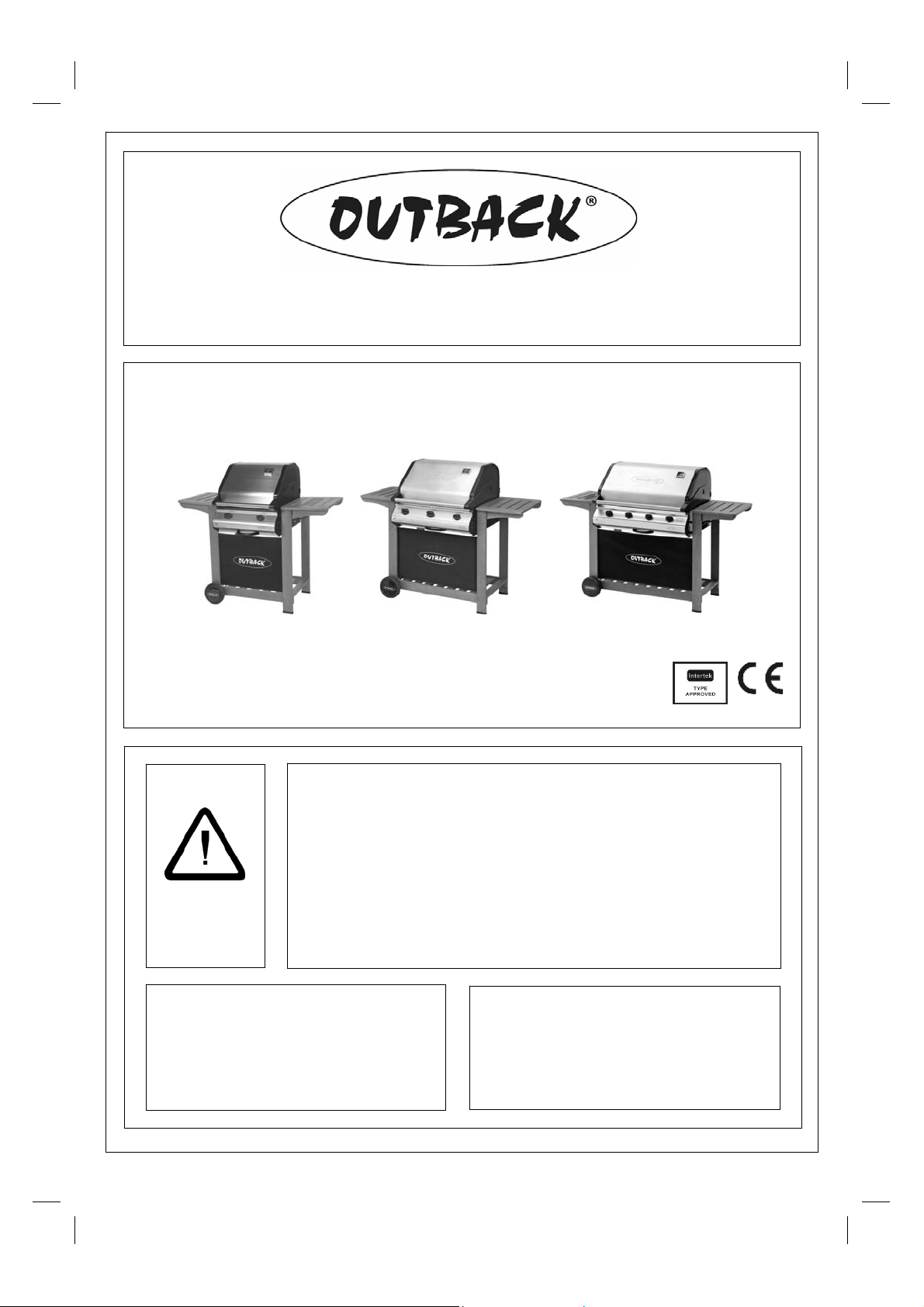
Gas Barbecues
Assembly an d Operati ng I nstruct ions fo r Ou t back®
Trooper/Hunter/Ranger Stainless Steel Gas Barb ecues
EN (Europe)
Photographs are not to scale.
Specifications subject to change
without prior notice. 0359
WARNING
• For outdoor use only. Not for commercial use.
• Read instructions before using the appliance. Failure to follow instructions could
result in death, serious bodily injury, and/or property loss.
• Warning: accessible parts may be very hot. Keep young children away.
• Do not m ove the appliance during use.
• Turn off the gas supply at the gas bottle after use.
• Any modification of the appliance, m is use, or failure to follow the instructions may
be dangerous and will invalidate your warranty. This does not affect your statutory
rights.
• Retain these instructions for future reference.
• Leak test annually , and whenever the gas bottle is removed or replaced.
• For Flare-up control please refer to the ‘OPERATION’ section of this manual.
FOR YOUR SAFETY
If you smell gas:
1. Shut off gas to the appliance.
2. Extinguish any open flame.
3. Open barbecue lid or hood.
4. If odour continues, discontinue use and
contact your local dealer.
FOR YOUR SAFETY
1. Do not store or use petrol or other flammable
vapours or liquids in the vicinity of this or any
other appliance.
2. A gas bottle not connected for use shall not be
stored in the vicinity of this or any other
appliance.
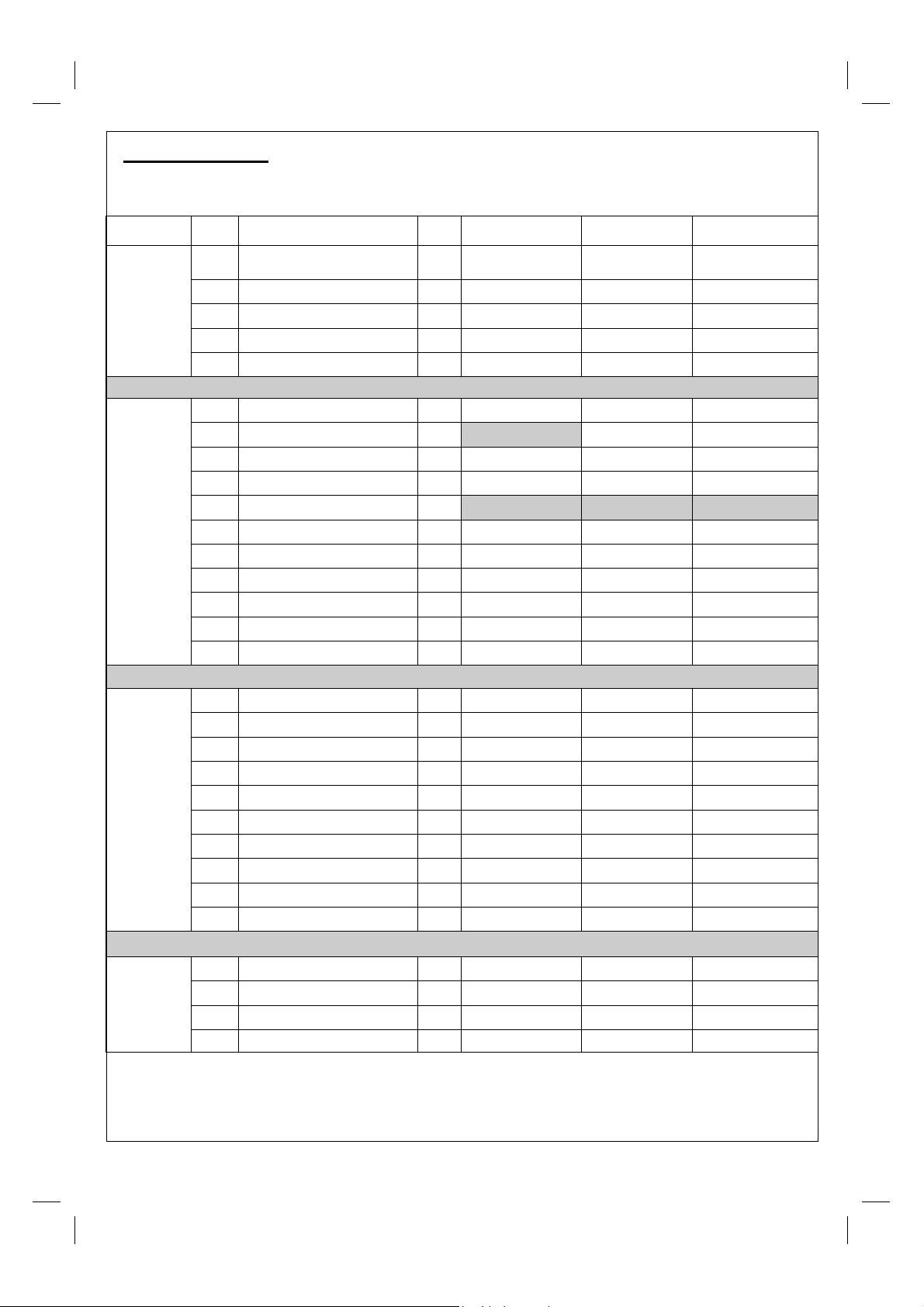
A. Parts List
Specifications s ubject t o change without prior notice. For more det ails o n hardware, please see
‘Hardware Refer ence Diagram ’.
CODE PART QTY
A1 Hood (Pre- Assembled to Body) 1
Outback® Tr ooper
Stainless St eel
Outback® Hunter
Stainless St eel
Outback® Ranger
Stainless St eel
HOOD
BODY
TROLLEY
HARDW ARE
A2 Hood Hinge Pin 2
A3 R-Clip 2
A4 Heat Gauge 1
A5 Warmi ng Rack 1
B1 Cooking Grill
B2 Rev ersible Cookin g Griddl e 1
B3 Lava Rock Basket 2
B4 Lava Rock (Packed in Basket) 2
B5 Hose (if su pplied)
B6 Body 1
B7 Burner
B8 Control Panel 1
B9 Knob
B10 Drip Tr ay 1
B11 Drip Tr ay Hand le 1
C1 Side Shelf 2
C2 Shor t Leg 2
C3 Long Leg 2
C4 Screen 1
C5 Trolley Base 1
C6 Axle 1
C7 Wheel 2
C8 Washer 2
C9 Locknut 2
C10 Wheel Hubcap 2
D1 Trolley Bolt 24
D2 Body Support Bolt 8
D3 Spacer 8
D4 Wingnut 8
2
2
2
2
3
3
1
4
4
Pre-Assembled Component
Quantity varies according to model purchased
Appearan ce, siz e, and construct ion may differ accordin g to model purchas ed
2
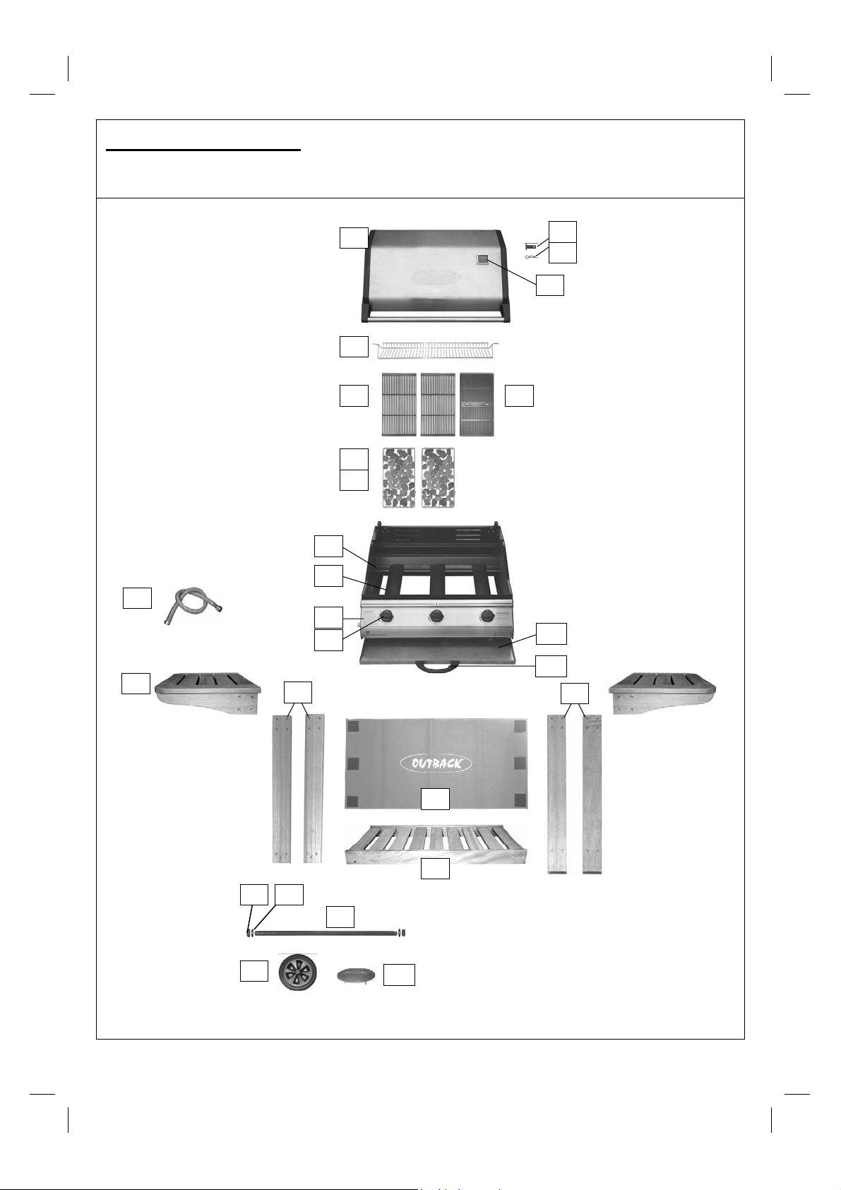
B. Parts Diagrams
Quantities vary accor ding to model purchased. Specificatio ns subject t o c hange without prior notice.
For more details on hardware, please see ‘Hardware Reference Diagram’.
B5
B6
B7
B8
B9
A1
A5
B1
B3
B4
A2
A3
A4
B2
B10
C1
C7
B11
C2
C4
C5
C8 C9
C6
C10
C3
3
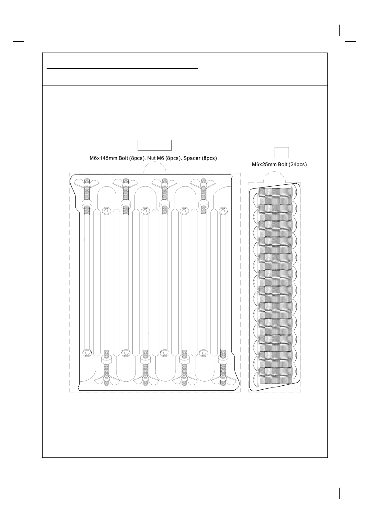
C. Hardware Reference Diagram
Specifications s ubject t o change without prior notice.
D2, D3, D4
D1
4
D. Assem bly
n TOOLS NEEDED FOR ASSEMBL Y:
Medium size flat blade or Philips/cr oss poi nt scr ew dr iver, adjustable spanner or metric spanner set.
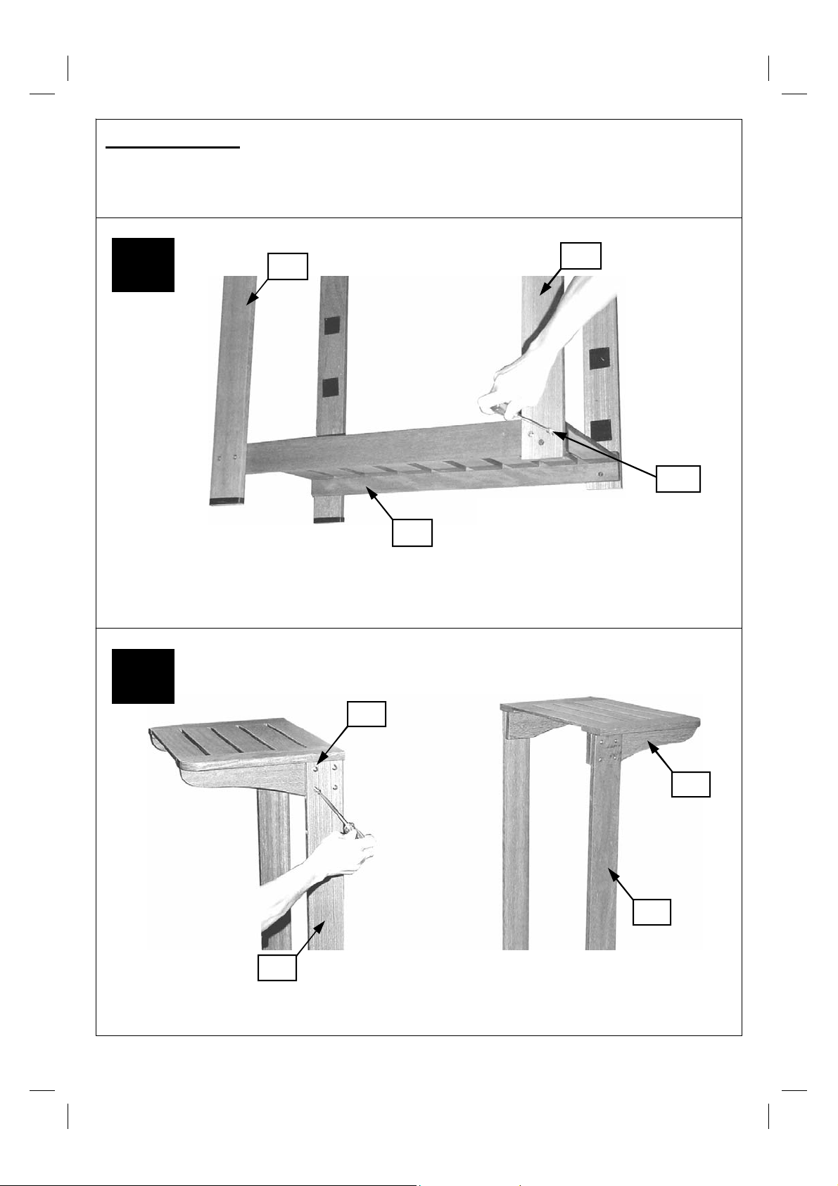
1
Attach the short (C2) and long legs (C3) to t he trolley base (C5) usi ng t he trolley bolts
(D1). Take care to fix the legs with Velcro attached as shown in the illustration.
C3
C5
(Photo depicts troll ey
from the reverse si de)
C2
D1
2
D1
C1
C3
C2
Attach the side shelves (C1) t o the short ( C2) and long (C3) legs using the trolley bolts (D1).
5
 Loading...