

Page 1
Assembly an d Operating In st ructi on s f or Outback®
Prof ession al Range Pro 4 & 6 Burner Gas Barbecues
Photographs are not to scale.
Specifications subject to change
without prior notice.
Gas Barbecues
0359
WARNING
If you smell gas:
1. Shut off gas to the appliance.
2. Exti ngui s h any ope n f l a m e.
3. Open bar bec ue lid or hood.
4. If odour continues, discontinue use and
FOR YOUR SAFETY
contact your local deal er.
• For outdoor use only.
• Read instructio ns be for e using t he appl ian ce . Fa ilure to follo w in stru ction s c ould
result in death, serious bodily injury, and/or property loss.
• Warning: acc essible parts may be very hot. Keep yo ung chi ld ren aw ay.
• Do not move the appliance during use.
• Turn off the gas supply at the gas cylinder after use.
• Any modifi cation of the ap pliance, mis use, or failure to foll ow the instructions
may be dange rous and wi ll invalidate your warranty. This d oes not affe ct your
statutory rights.
• Retain these instructions for future reference.
• Leak t e st your barbe cu e ann u al ly. C he ck th e ho se con n e cti on s ar e ti g ht an d leak
test them each time you reconnect the gas bottle.
FOR YOUR SAFETY
1. Do not store or use petrol or other flammable
vapours or liquids in the vicinity of this or any
other applianc e.
2. A gas cy linder not connected for use shall not
be stored in the vicinity of this or any o ther
appliance.
Page 2

Part s List
Quantities vary accor ding to model purchased. Specificatio ns s ubject to change without prior notice.
For more details on hardware, please see ‘Hardware Refer ence Diagram’.
CODE PART QTY Professional Range Pro 4 Professional Range Pro 6
4 6
5 7
4 6
HOOD
BODY
TROLLEY
ROTISSERIE
HARDW ARE
A1 Hood Handle 1
A2 Hood 1
A3 Heat Indicator Assembly 1
A4 Warming Basket 1
B1 Barbecue Body 1
B2 Burner
B3 Back Burn er 1
B4 Control Panel 1
B5 Knob ( Inclu ded Back Burner Knob)
B6 Drip Tr ay 1
B7 Drip Pa n 1
B8 Foil Lin e r 1
B9 Flame Tamer
B10 Grill 3
C1 Side Burner 1
C2 Side Burner Grid 1
C3 Side Burner Valve 1
C4 L/H Side Burner Shelf with Lid 1
C5 R/H Side Shelf 1
C6 Hose 1
C7 L/H Panel 1
C8 R/H Panel 1
C9 Back Pa nel 1
C10 Botto m Pan e l 1
C11 Body Support 1
C12 Cabinet Support 1
C13 L/ H Door 1
C14 R/H Door 1
C15 Caster 2
C16 Lockabl e Cast er 2
C17 H eat Shield 1
C18 Mounting Bracket 1
C19 Ignition Assembly 1
C20 Side Bur ner Knob 1
D1 Rotisserie Handle 1
D2 Fork 2
D3 Spit Rod 1
D4 Motor 1
D5 L/H Brack et 1
D6 R/H Bracket 1
E1 Scre w, M6x15 50
E2 Nut, M6 16
E3 Scre w, M4x10 8
E4 Screw, ST4.0 x 10 4
E5 Scre w, M5 x 10 4
E6 Nut, M5 4
E7 Screw 2
Pre-Assembled Component
Quantity varies according to model purchased
Appearan ce, siz e, and construct ion may differ accordin g to model purchas ed
2
Page 3
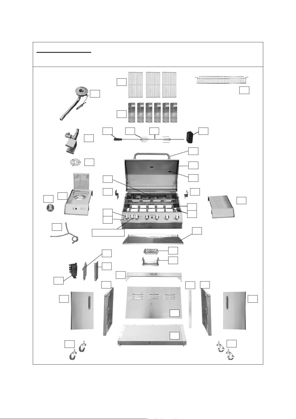
Part s Diagrams
Quantities vary accor ding to model purchased. Specificatio ns s ubject to change without prior notice.
For more details on hardware, please see ‘Hardware Refer ence Diagram’.
B10
C1
B9
D1 D2 D3 D4
C3
A1
A4
C20
C2
B4
C4
B5
B4
C6
Back Burner Knob
C18
C17
C11
C19
C7 C8
C13 C14
B8
B7
A2
A3
D6 D5
C5
B1
B2
B6
C12
C15
C9
C10
C16
3
Page 4
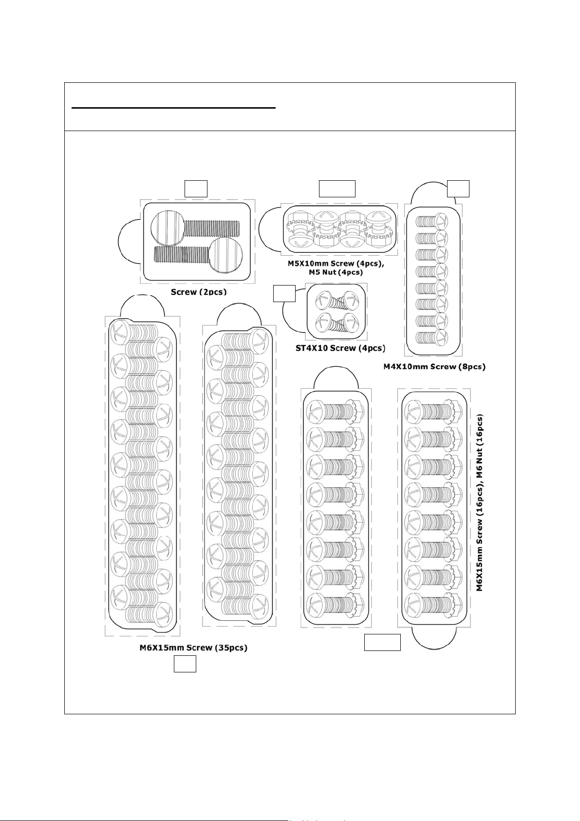
Hard ware Reference Di agram
Specifications s ubject t o change without prior notice.
E7 E5, E6 E3
E4
E1
E1, E2
4
Page 5
Assembly
IMPORTANT!
• Tools Require d: Medium size flat blade or Phillips/Cr osspoint screw driver, adj ustable spa nner or
metric spanner set
• The assembly of this barbecue req uires 2 people.
• Carefully unpack the parts from the box and remove all internal packaging before commencing
assembly. All loose items i ncluding the grills, flame tamers and war ming basket must be removed
from the body.
• Whilst every care is taken in the manufacture of this product, care must be taken during assembly
in case sharp edges are present.
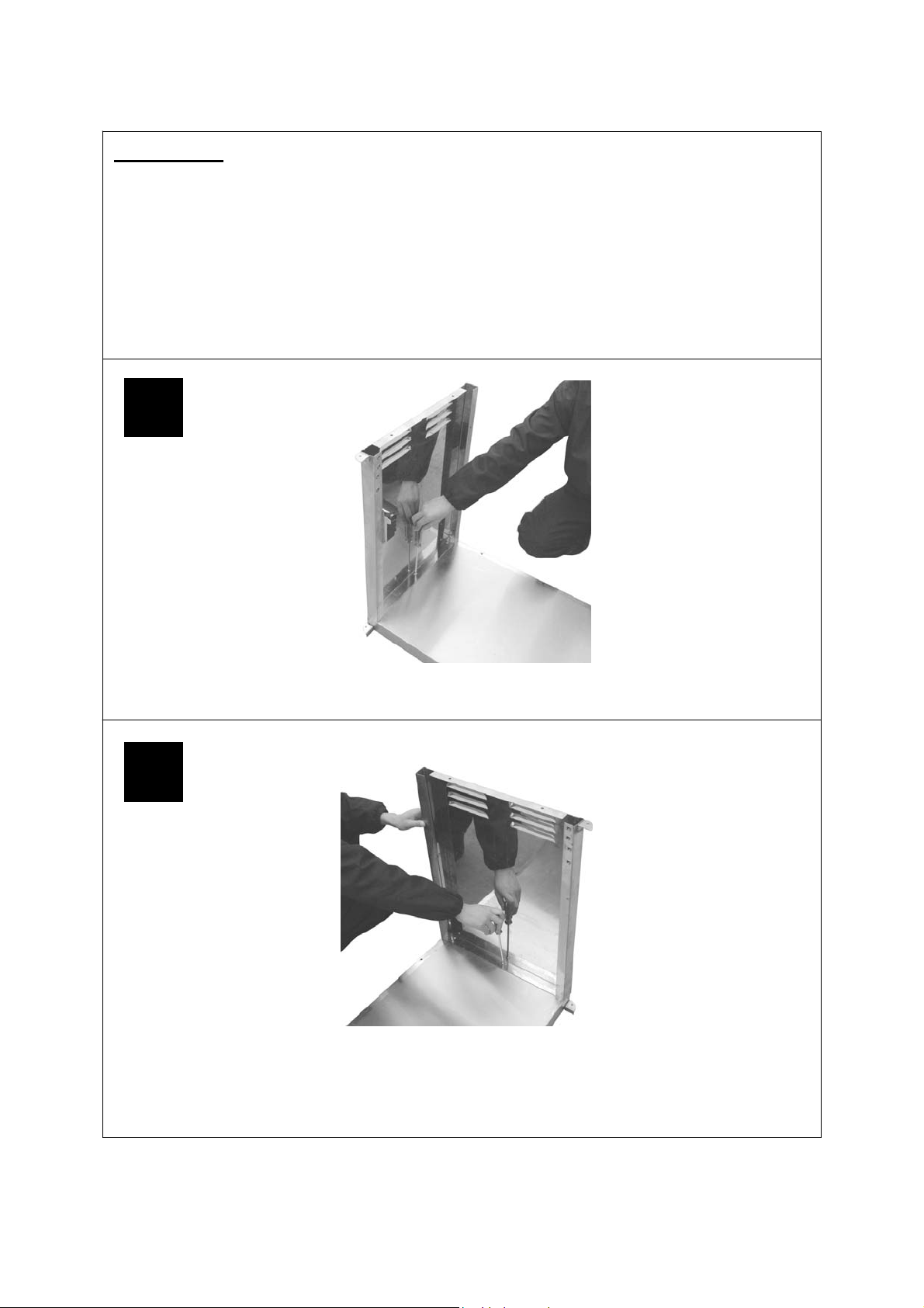
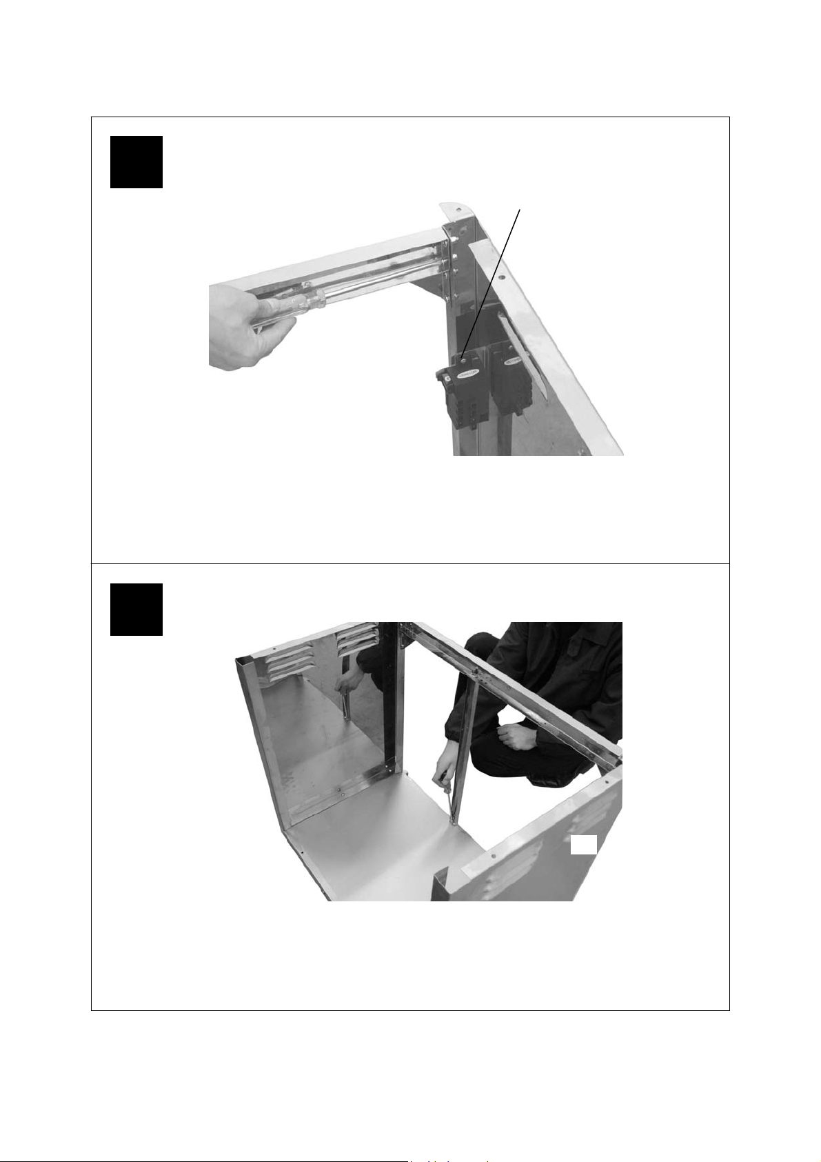
1
L/H
* A sticker on the panels
indicates the position for
easy assembly.
Attach the L/H Panel (C7) to the Bottom Panel (C10) using the Screws (E1) and Nuts (E2).
2
R/H
Attach the R/H Panel (C8) to the Bottom Panel (C10) using the Screws (E1) and Nuts (E2).
5
Page 6
3
I gnition Assembly
L/H
Attach the Body Support ( C11) to the L/H (C7) and R/H (C8) Panels using the Screws (E1) .
4
R/H
L/H
Attach the Cabinet Support ( C12) bet ween the Body Support and Bottom Panel using
the Screws (E1).
6
Page 7

5
L/H
E4
E1
Attach the Back Panel (C9) to the assembled portion of the cabinet using the Screws (E1,E4).
R/H
6
L/H
Turn over the cabinet.
Attached the Casters (C15) and the Lockable Caster s ( C16) t o t he Bottom Panel
(C10) using the Screws( E1) .
7
R/H
Page 8
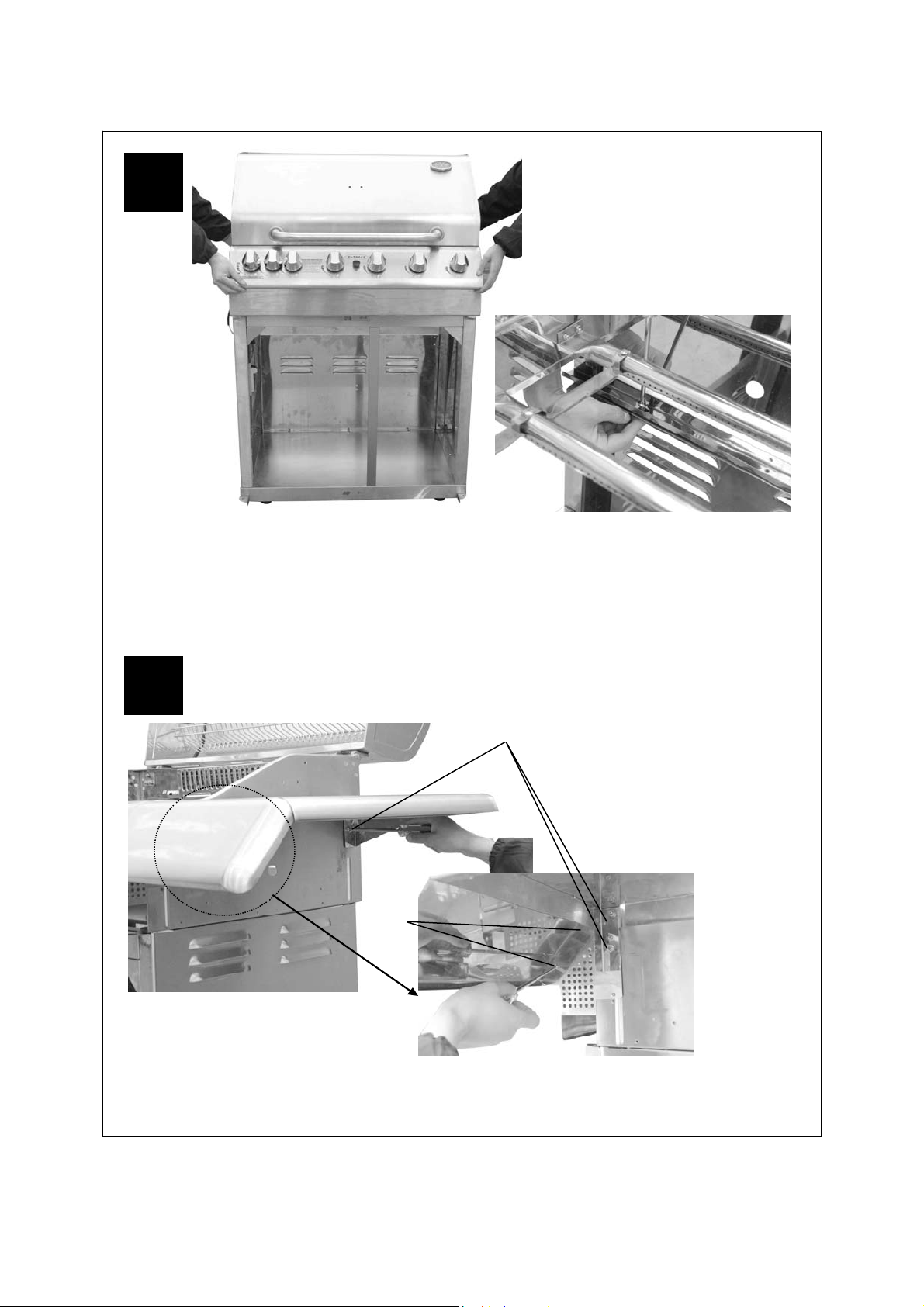
7
Lay the Barbecue Body (B1) onto the supports of the cabinet Carefully . WARNING: DO NOT
RELEASE THE BARBECUE BODY WHILE THE BARBECUE HAS NOT BEEN PROPERLY
SEATED. THIS MAY RESULT IN INJURY OR DAMAGE TO YOUR BARBECUE.
Open Hood(A2), Connect t he Body to the cabinet using the Screw s( E1) .
8
E1
E3
Attach the Side Burner Shelf (C4) and side Shelf (C5) t o side panel of Body using
the Screws(E1, E3).
8
Page 9

9
Valve
Attach the Valve (C3) t o the Side Burner Shelf (C4) using the Screws(E3) .
Then push the Side Burner Knob (C20) o nto the Valve stem.
Side Burner knob
1
Valve
10
Venturi tube of the side burner
side burner bracket
2 3
Feed the venturi tube of the side burner ( C1) t hrough the hole in the side burner shelf, and slide
the end of the venturi tube over the tip of the valve, then connect the burner to side burner
bracket using the Screws (E3) .
9
Page 10

11
Open L/H side burner lid and place the Grid (C2) onto the burner.
12
Connect the wires t o the Ignition Assembly (C19) as shown on t he next page.
Attach the Electronic Ignition Battery in to the Ignitio n.
Note: The Ignitio n Assembly were Assembled on the L/H Panel.
10
Page 11

13
Outback® Professional
Range Pro 4 Electronic
Ignition Assembly Diagram
Red
Red
Blue
Side Burner
Black
Blue
Back Burner
Black
9V Battery
(Included)
Connect the wires as shown in the
diagram.
Outback® Professional
14
Range Pro 6 Electronic
Ignition Assembly Diagram
Ignition
Pushbutton
Yellow Orange
Yellow
Red
Orange
Red
Back
Burner
Side
Burner
9V Battery
(Included)
Connect the wires as shown in the
diagram.
Ignition
Pushbutton
11
Page 12

15
Connect to t he side burner valve Connect to t he valve of Body
Connect the gas hose to t he BBQ Body and L/H Side Burner Shelf. Ensure the mating
faces of t he connectio n are cl ean and not damaged. Do not use a ny seali ng tape, past e, or
liquid on the joint. The nut must be tightened w ith the use of a spanner. Do not us e force
which may damage the assembly.
16
Push down the pins on the inside of the doors and insert the doors (C13,C14) into place.
12
Page 13

17
Remove the plastic wr ap f r om the Flame Tamers (B9) and lay them into the body ensuri ng
that they lie level within the body. Lay the Grills (B10) into p la c e.
18
Attach the L/H and R/H Rotisserie Brackets (D5, D6) to the Barbecue Body using the
Screws ( E5) and Nuts (E6).
13
Page 14

19
Hang the Rotisserie Motor (D4) to the R/H Bracket. Place the Forks (D2) onto the Spit Rod
(D3) and insert the Spit Rod into the Slot in the Motor.
20
Slide the Drip Tray (B6) into place under neat h the barbecue body.
Place the Foil Liner (B8) into the Drip Pan (B7) and slide into place.
14
Page 15

21
Appearance, size, and construction may differ according to model purchased,
Number of gas valves to be tested may vary according to model of barbecue.
Assembly is now complete.
All joints and connections must now be l eak t ested befo r e usi ng the ba r be cue.
For details of leak tes ting, please r efer to instruct ions on P age 19.
15
Page 16

Rotisserie Kit Assembly
Specifications s ubject t o change without prior notice.
D4
D3
D6
D2
D1
D5
E6
PARTS LIST:
D1 Rotisserie Handle 1
D2 Fork 2
D3 Spit Rod 1
D4 Motor 1
D5 L/H Bracket 1
D6 R/H Bracket 1
E5 Screw, M5x10 4
E6 Nut, M5 4
E7 Screw 2
OTHER REQ UIREM ENTS:
2 D-Size Batteries (1.5V) (Not Included)
ASSEMBLY:
1. Mount the R/H motor mounting bracket
(D6) on the right hand side of the barbecue
body. Mount the L/H mounting bracket
(D5) on the other side of the barbeque
body. Both brackets should poi nt outwards
from the outer sides of the barbecue body.
2. Insert batteries into motor. N.B. Mot or can
be also run using 3V DC adaptor.
3. Slide the motor (D4) onto the R/H motor
mounting bracket ( D6).
E5
E7
NOTE: The rotisserie motor should never be
used in the event of rain. We recommend the
motor is detached from the mounting bracket
whe n not in use.
OPERATION:
1. Carefully remove the cooking surfaces and
the warming basket fr om the barbecue.
2. Slide one of the spit for ks onto the spit rod
and tighten its thumb screw to secure it
into place. Insert t he pointed end of t he spit
rod into the meat being cooked and slide
the meat towards the centre of the rod.
Make sure the fork is fully into the meat.
Slide the other fork onto the rod, into the
meat, and tighten the thumb screw once in
place. For optimal rotisserie cooking, food
must be placed securely onto the middle of
the spit rod and balanced so that the
rotisserie can rotate freely without
interference from any barbecue surfaces.
Any loose sections of meat should be
secured so they do not hang down and
interfere with the rotation of the spit rod.
Do not overload the rotisser ie. A chicken or
joint of meat of approximately 2kg should
be the maxi mum.
3. Insert the pointed end of the spit rod into
the motor. Lay the other end of t he spit r od
onto the opposite bracket.
4. Light the grill as specified in your
barbecue’s instructio ns.
5. Turn on the rotisserie motor to begin
rotisserie cooking. The hood has been
designed so that it may be closed during
rotisser ie cooki ng.
6. Always cook foods on the lowest flame
setting to avoid burni ng or overcooking.
7. The handle of the spit rod can be
unscrewed to allow f or simulta neous use of
the side burner.
16
Page 17

nESSENTIAL INFORMATION
Please read instructions before using your barbecue.
BEFORE YOU USE Y OUR BAR BE CUE ( also see installati on)
• Perform a leak test. This is the only safe and sure way to detect any gas leaking from joints and
connections of the barbecue after assembly. Follow the leak test instructions on page 19. Check that the
gas hose is free of any tension, twisting, cuts, or cracks.
• Make sure your barbecue is in a safe place. It must be outdoors, on level ground and not below ground
level. Ensure that the barbecue is at least 1 metre away fro m any fla mmable materials, including tree s
and fences and that there are no heat sources near the barbecue (cigarettes, open flames, spark etc.)
• Check that you have the correct gas bottle and regulator for your barbecue. Never place the gas bottle
inside the trolley cabinet.
GETTI NG STARTE D ( also see o perati on)
• Main Burners - Open the hood of your barbecue. Never light your barbecue with the hood closed. Turn
the gas regulator or gas bottle valve to the ‘on’ position. Push the control knob in on the burner you wish
to light and turn it to the high position. Push and hold in the igniter button in the centre of the control
panel for 4 to 5 seconds to light the burner. Light all other burners in the same way making sure each
burner is alight before attempting to light the next. IF ANY BURNER FAILS TO LIGHT, TURN OFF T HE
GAS AT THE BURNERS AND THE BOTTLE, WAIT 5 MINUTES AND TRY AGAIN. If the burners cannot
be lit using the ignition system, turn to the manual lighting instructions on page.20.
• Once the burners are lit, turn all the main burners to the high setting for 3-5 minutes to pre-heat the
barbecue. This should be done before each session. When pre-heating is co mplete, cooking can begin
taking extra care if the burners are used in the high position.
• To prevent food sticking we recommend that you use a long handled brush to apply a light coat of
cooking oil to the grills before each barbecue session.
• Side Burner - Open the lid of the side burner. Never light the side burner with the lid closed. Turn the gas
regulator or gas bottle valve to the ‘on’ position. Push the side burner control knob in and turn it to the
high position. Push and hold in the igniter button in the centre of the control panel for 4 to 5 seconds t o
light the burner. IF T HE BURNER FAILS T O LIGHT, T URN OFF T HE GAS AT T HE BURNER, WAIT 5
MINUTES AND TRY AGAIN. If the burner cannot be lit using the ignition system, turn to the manual
lighting instructions on page.20.
• Back (Rotisserie) Burner– From off position, push in and turn the back burner control knob anti-clockwise
to high position. Push and hold in the igniter button in the centre of the control panel for 4 to 5 seconds to
light the burner. IF T HE BURNER FAILS T O LIGHT, T URN OFF T HE GAS AT T HE BURNER, WAIT 5
MINUTES AND TRY AGAIN. If the burner cannot be lit using the ignition system, turn to the manual
lighting instructions on P.20. WARNING: T he main burners must never be used while using the back
burner. This could result in overheating the barbecue or starting a fat fire.
• If a fat fire should occur during cooking, and if safe to do so, turn off the burners and the gas at the bottle
and wait for the fire to go out. Do not pull out the drip tray or douse with water.
• Never douse a barbecue with water.
• Never move a barbecue when lit.
• Never leave a lit barbecue unattended
• Never handle hot parts with unprotected hands
• Keep children, animals, and elderly people a safe distance from a lit barbecue.
WHEN Y OU HAVE FINI S HE D COOKING ( also see care and maintenance)
• Turn all the main burners to the high position for 3 to 5 minutes to burn off any food residue from the
cooking surfaces and burners. When the barbecue has cooled, the burnt residue can be easily removed
using a damp, non abrasive cloth on the cooking surfaces and a brass wire brush on the burners and
flame tamers. We do not recommend putting grills in a dishwasher due to their weight.
17
Page 18

• When the barbecue has cooled, scrape away any food and fat residue from the drip tray and discard .
Empty and clean the Foil Liner. These routines must be completed after each session.
STORAGE
• Ensure the barbecue is properly cooled.
• If you intend to leave your barbecue outside, make sure it is protected from the elements with a heavy
duty cover. These are available from most Outback® stockists.
• Store your barbecue in a cool dry place. It must be inspected on a regular basis as damp or
condensation can form which may result in da mage to the barbecue. It may be necessary to dry the
barbecue and the inside of the cover if used. Mould can grow under these conditions and should be
cleaned and treated if required. Chrome plated warming racks etc. should be coated with cooking oil.
Wrap the burners in aluminium foil to help prevent insects or other debris from obstructing the burners.
• The gas bottle must be always be disconnected from the barbecue and stored in a well ventilated area at
least 1 metre away from any fi xed ignition source. Do not store inside residential accommodation. Neve r
store cylinders below ground level (e.g. cellars). Do not let children tamper with bottles.
IMPORTANT INFORMATION
• For use with LPG bottled gas only. A fixed pressure regulator of 28-30mbar must be used for butane o r
37mbar for propane. The use of an adjustable regulator is dangerous and must never be used with thi s
barbeque.
• This product is for outdoor use only. Do not use indoors.
• Do not use below ground level as LP gas is heavier than air so if a leak occurred the gas collected at a
low level could ignite in the presence of a flame or spark.
• Do not use or store gas bottles on their side as this could allow liquid gas into the supply pipes with
serious results.
• Never place the gas bottle inside the trolley cabinet.
• Leak test the barbecue annually. Check that the hose connections to the barbecue are tight and leak test
whenever the gas bottle is reconnected.
• Always turn off the gas at the bottle when not in use.
• Do not use aerosols near this barbecue.
GAS, RE GULATOR AND HOSE
This barbecue, hose, (and regulator, if included), are approved for use in the UK. T he barbecue is also
approved for use in other countries as listed on the control panel and in the Technical Specifications included
in the barbecue manual. If the barbecue is intended to be used outside of the UK, the consumer MUST seek
advice from the local qualified gas supplier as to the suitability of the barbecue and with regards to the
correct hose and regulator that they should be using.
This barbecue can run on propane or butane LPG (liquid petroleum gas) bottled gas. For optimal
performance we recommend the use of propane gas which is supplied under a number of different names
and bottle colours. Butane gas can be used but it may restrict the heat output available from the burners,
particularly when the gas temperature falls below + 10 degrees Celsius. If in doubt, please consult your g as
dealer/distributor.
For optimal performance, we suggest the following:
MODEL BUTANE MINIMUM BOTTLE SIZE PROPANE MINIMUM BOTTLE SIZE
Professional Range Pro 4 x 10kg
Professional Range Pro 6 x 10kg
Suitable regulator:
Butane – outlet pressure 28-30mbar
Propane – outlet pressure 37mbar
18
Page 19

Hose
• Check that the gas hose does not touch any part of the barbecue that may become hot during operation.
• If the hose shows any sign of da mage it must be replaced with a hose that is suitable for use with LP G
(liquid petroleum gas) and meets British Standards.
• The length of hose should not exceed 1.5 metres.
Please note: the date on UK orange hose is the date of manufacture – not the expiry date.
You must have the correct gas bottle , re gulator, and hose for the barbecue to operate safely and
efficiently. Use of an incorrect or faulty regulator is dangerous and will invalidate the warranty on
this product. If you are unsure, please check with your local gas dealer.
INSTALLATION
Precautions:
• Only use this barbecue in a well-ventilated outdoor area.
• Check that the barbecue is not placed UNDER any combustible surface.
• The sides of the barbecue should never be closer than 1 metre to any combustible material.
• Do not obstruct any ventilation openings in the barbecue body
• Confirm all control knobs are in the off position before connecting the regulator.
• Always connect the regulator in accordance with the regulator and gas cylinder suppliers instructions.
• The casters should always have the brakes on when the barbecue is in use.
LEAK TESTIN G
Always perform a leak test in a well-ventilated area.
Step 1 - Confirm all control knobs are in the off position.
Step 2 - Detach the barbecue control panel located across the front of the barbecue body by pulling off the
control knobs and removing the control panel retaining screws.
Step 3 - Turn on the gas at the gas cylinder or regulator
Step 4 - Check for leaks by brushing a solution of ½ water and ½ liquid soap over all the gas system joints,
including all valve connections, hose connections, and regulator connections.
Step 5 - If bubbles form over any of the joints there is a leak
• Turn off the gas
• Retighten all joints
• Repeat test
• If bubbles form again do not use the barbecue and contact your local distributor for assistance.
OPERATION
Your barbecue is not designed to be used with more than 50% of the cooking area as a solid plate – this
includes baking dishes. If more than 50% of your cooking area is covered by a solid cooking surface, the
barbecue could overheat causing damage that is not covered by warranty.
Grill cooking
The burners heat the flame tamers beneath the grill that, in turn, heats the food. The natural juices produced
during cooking fall onto the flame tamers and vaporise to form smoke. The smoke then rises and ‘bastes’ the
food, giving it that unique barbecued flavour. More even cooking of food will be achieved with the hood down
which will also hold the heat in. This should only be done with the burners on a low to medium setting.
Roasting (hooded barbecues only)
If your barbecue is supplied with a roasting hood rather than a lid you are able to roast or bake in a similar
way as in a conventional gas oven. It is advisable not to place fatty food onto the war ming basket to avoid
the possibility of juices and fat running down the back of your barbecue. For best results place the food you
wish to bake or roast in a metal baking tray and set it on one side of the cooking grill. Turn the burners
directly under the food to the ‘OFF’ position and the burners opposite the food to the ‘Medium’ setting. Close
the lid and this will form an oven to cook the food ‘indirectly’. Monitor the temperature using the temperature
19
Page 20

gauge on the lid. If the internal heat becomes too high, turn the burners to the ‘low’ position. It is not
necessary or advisable to have all of the burners on high when the hood is closed. If the hood is opened
during cooking to check on the progress of the food, please allow e xtra cooking time for the barbecue t o
regain its temperature. Take care when opening the hood as hot steam can be released on opening.
Back (Rotisserie) Burner
The barbecue is equipped with a back burner which can be used for cooking with a rotisserie. When using a
rotisserie with the back burner, a baking dish or si milar must be placed on the grills directly under the foo d
being cooked to catch the drips.
Warming Basket
Warming baskets are a convenient way to keep cooked food warm or to war m items such as bread rolls.
Care should be taken to ensure any items placed in the warming basket are cooked through and do not
continue to cook and drip fat or meat juices, which could drip onto the hood and down the back of the
barbecue.
Flare-up control
Flare-ups will often occur when food is barbecued as fat and juices fall onto the fla me ta mers. Some fat is
necessary to give the food its barbecued flavour but excessive fat can result in a flare-up. To avoid flare-ups
it is advisable to trim excess fat from meat and poultry before grilling, use cooking sauces and marinad es
sparingly, and try to avoid very cheap cuts of meat or meat products as these tend to have high fat and water
contents. Flare-ups occur more at the start of cooking, particularly with processed meat products, and it may
be necessary to turn the burners down to their lowest setting to start with and then turning up at a later stage
in the cooking process. The barbecue should also not be overloaded. Some parts of the cooking area are
hotter than others. The hottest areas will be above the burners which will be where the flare ups will normally
start. By leaving free space you can si mply move the food away fro m the flare up to a cooler area until th e
flare up has subsided.
Fat Fires
The foil liner must be e mptied and the drip tray cleaned of food debris after each cooking session. If the
barbecue is to be used for co mmercial use or large gatherings, it will be necessary to turn off and cool th e
barbecue every two hours to remove food debris from the drip tray and clean out the foil liner, the time
between cleaning may need to be reduced if very fatty foods or cheap meat products are being cooked.
Failure to do this may result in a fat fire, which may cause injury and could seriously damage the barbecue.
In the event of a fat fire;
• If safe to do so, turn all control knobs to the ‘off’ position
• Turn off the gas at the cylinder
• Keep everyone at a safe distance from the barbecue and wait until the fire has burnt out.
• Do not close the hood of the barbecue.
• NEVER DOUSE A B ARBECUE W IT H WAT ER. IF AN E XT INGU ISHER IS USED, IT SHOULD BE A
POWDER TYPE.
• DO NOT REMOVE THE DRIP TRAY
• If the fire does not seem to be abating or appears to be worsening, contact your local Fire Brigade for
assistance.
Manual lighting instructions
• Insert a long, lit match through the match-lighting hole in the right hand side of the body of the barbecue
until the lit end is alongside the right hand burner. Push and turn the right hand control knob anticlockwise to the high position taking care to protect yourself from flames.
• When the burner is lit turn on the remaining burners from right to left.
• Confirm that each burner is lit before turning on the next burner
• To light the side burner place the lighted end of a long match alongside the side burner. Push and tur n
the side burner control knob anti-clockwise to the high position taking care to protect yourself from
flames.
• To light the back burner, place the lighted end of a long match in front of the burner. Push and turn th e
back burner control knob anti-clockwise to the high position taking care to protect yourself from flames.
20
Page 21

WARNING: The main burne rs must never be use d while using the back burne r. This could result
in overheating the barbecue or starting a fat fire.
• If the right hand burner or side burner fails to light, turn off the gas and contact your local
Outback dealer or our customer services department on (01622) 671771 for assistance.
WARNING: When using the back burner, the main burner must not be used. Turn off all main burners before
lighting back burner.
CARE AND MAINTENANCE
Do not leave the barbecue uncovered and exposed to the elements when not in use. Heavy duty covers are
available from your Outback® stockist. Even when your barbecue is covered for its protection, it must be
inspected on a regular basis as damp or condensation can form which may result in damage to the
barbecue. It may be necessary to dry the barbecue and the inside of the cover. Any rust that is found that
does not come into contact with the food should be treated with a rust inhibitor and painted with barbecue
paint or a heat resistant paint. Chrome plated warming racks etc. should be coated with cooking oil.
Burner Assembly
To remove the burners (see photos):
1. Remove the cross channel from burner.
2. Remove the bolts/nuts from end of burner.
3. Gently pull the burner mouth away from the valve injector.
4. Lift the burner out and remove the screws from front of burner.
To re-install the burners (not depicted):
1. Slide the burner mouth over the valve injector. The injector should sit centrally within the burner venturi
tube.
2. Install the electrode onto the burner by screws.
3. Install the burner onto the body by bolts/nuts.
4. Install the cross channel onto the burner by screws.
1
2
3 4
• Your burners have been preset for optimal flame perfor mance. You will nor mally see a blue flame,
possibly with a small yellow tip when the burner is alight. If the fla me pattern is significantly yellow, thi s
could be a problem caused by grease from cooking blocking the burner or spiders or other insects in the
burner venturi. This can result in the flow of the gas and air mixture being restricted or blocked which may
result in a fire behind the control panel causing serious damage to your barbecue. If this happens, the
gas should be immediately turned off at the bottle.
• Burners should be inspected and cleaned on a regular basis in addition to the following conditions:
1. Bringing the barbecue out of storage.
2. One or more of the burners do not ignite.
3. The burner flame pattern is significantly yellow.
4. The gas ignites behind the control panel.
• To clean a burner, remove it from the barbecue. The outside of the burner can be cleaned with a brass
wire brush.
• Clean the portholes with a pipe cleaner or piece of wire. Take care not to enlarge the portholes.
• Clean the air inlets on the end of the venturi tube with a bristle brush (i.e. an old toothbrush).
• Clean the venturi tube with a pipe cleaner or piece of wire. You may need a torch to see into the venturi
tube to make sure it is clear.
• Turn the burner up on end and lightly tap against a piece of wood to dislodge any debris from inside.
Injectors locate into the central hole
of the burner venturi tube.
21
Page 22

Troubleshooting
Problem
Burners will n ot light
using the igni tion
system
Burner will no t light
with a match
Possible Cause
LP gas cylinde r is empty Replace with full gas cylinder
Faulty regulator Have regulator checked or replace
Obstructions in burners Clean burners
Obstructions in gas jets or
gas hose
Elect rode or pus hbutt on
Ig niti on wir e i s lo ose or
disconnect ed
Elect rode or w ire is da m age d Change e le ctrod e and wire
Incorrect electrode gap The electr ode needs to have a gap
Flat b at t ery in ignition assembly Replace battery
Poor connect ion of batt ery in
Ignition assembly.
LP gas cylinder is empty Replace with full gas cylinder
Solution
Clea n jets and ga s hose
Reconnect wire
of approximately 3 to 4mm betw een
its tip and the burner. Adjust if
required.
Ensure b attery is firmly
Pushe d onto conne c tors.
Faulty regulator Have regulator checked or replace
Obstructions in burners Clean burners
Obstructions in gas jets or
gas hose
Low flame or
flashback (fire In
burner t ub e - a
hi ssing or roari ng
noi se may be he ard)
Gas valve knob
di fficult to turn
LP gas cylinder too small Use larger gas cylinder
Obstructions in burners Clean burners
Obstructions in gas jets or
gas hose
Windy c ond iti ons Use BBQ in a more s helt ered posit io n
Gas val v e j amm ed Repl ace ga s valv e
Clea n jets and ga s hose
Clea n jets and ga s hose
22
Page 23

Cleaning
Material Where used Cleaning Method Recommended
Chromium
plated
Warm ing basket Wash with hot soapy water. A ch rome cleaner may be used if
required. To prevent rustin g, wipe with cooking oil after
rins ing and drying .
Do not use abrasi ves.
Stainless
Steel
Hood
Cabinet
Side shelves
Control panel
Grills
Burner
Fla m e Tamers
Wipe with a cloth wrung out in hot soapy water.
A stainless steel clea ner ma y be used if required.
Do not use abrasives.
Any food debris should be removed on a regular ba sis.
A brass wir e brush can be used.
Burners should be removed on a regular basis for inspection
and cleani ng as det ailed on P.21.
Flame tamers can be cleaned by scraping off excess
deposits with a plastic or wooden scraper or a brass wire
brush
Galvanised Drip tray Excess fat a nd food debri s m ust be removed using a pl astic
or wooden scraper. Th is needs to b e carri ed out between
each use of the BBQ. Excessive build up is likely to lead to a
fat fi re which can be hazardous and damage the BBQ. This
is not a fault in the BBQ and therefore is not covered by
the t erm s of the warranty.
If required, the dri p tray and foil li ner can be washed in hot
soapy water.
T echn ical Specifications
Model Name
Professional
Range Pro 4
Professional
Range Pro 6
Back Burner 2.9kW 1 0.86mm
Side Burner 2.9kW 1 0.86mm
Countries of Use:
I
BE, CY, CZ, EE, FR, GR, IE, IT, LV, LT, LU, PT, SK, ES, CH, GB, RO
3+ (28-30/37)
BG, CY, CZ, DK, EE, FI, GR, LV, LT, LU, MT, NL, NO, SK, SI, SE, TR, IS
I
3B/P(30)
AT, DE, HU, SK, CH
I
3B/P(50)
PL
I
3B/P(36)
CE
Approval
0359
359BS706
Heat Input Burners
14.1kW 4 0.94mm
17.6kW 6 0.86mm
23
Injector
Size
Gas /Pressure
Butane/28-30mbar
Propane/37mbar
Page 24

OUTBACK UK LTD
LIMITED 10 YEAR WARRANTY
OUTBACK barbecues are warranted to the original pur chas er against defects in materials and
workmanship. Porcelain coated barbecue bodies, porcelain coated roasting hoods and
stainless steel roasting hoods are warranted for a period of ten (10) years from the date of
purchase. Stainless s teel burners ar e warranted for a period of two (2) year s from the date of
purchase. O UTBACK UK will, w ithin this period, s upply replacem ents f or defect ive parts fr ee
of charge provided that:
♦ The prod uct has not bee n used for trade, professional or hire purposes.
♦ The prod uct has not bee n subjected to mis use or neglect, incl uding f at f ir es and flare ups
or use of a faulty or incorrect regulator.
♦ The prod uct has not s ustai ned damage thro ugh for eig n objects, s ubsta nces or accidents.
♦ The care a nd mai nte nance instructi ons given in your Outback manual ha ve been followed.
This warr anty is off er ed as an extra benefit and is in addition to the customers’ statutory rights.
Outback UK does not war r anty in any way t he gas cylinder.
If you have any queries regardi ng the assembly or use of your barbec ue please contact
Outback UK
For reference and correspondence, record your serial number here.
(See sticker on side of barbecue body.)
Serial No.__________________
This number may be required when ordering spare parts or accessories.
A part reference number may also be required where applicable.
In the unlikely event that you experience
problems with this barbeque, please contact:
e-mail: customerservice@outbackuk.com
Customer Service
Outback UK
Unit 2 Farleigh Hill
Tovil
Maidstone
Kent ME15 6RG
Tel: 01622 671771
Fax: 01622 673101
website: www.outbackuk.com
Publ ish ed October 2007
24
 Loading...