

Page 1
0359
Photographs are not to scale.
Specifications s ubject to change
without prior notice.
Elite Series Barbecues
Assembly and Operating Instructions for Outback® Society/Granite,
Outback® Manhattan/Graphite, and Outback® Monarch/Mercury Flatbed Gas Barbecues
WARNING
• For outdoor use only.
• Read instructions before using the appliance. Failure to follow instructions
could result in death, serious bodily injury, and/or property loss.
• Warning: accessible parts may be very hot. Keep young children away.
• Do not move the appliance during use.
• Turn off the gas supply at the gas bottle after use.
• Any modification of the appliance, misuse, or failure to follow the instructions
may be dangerous and will invalidate your warranty. This does not affect your
statutory rights.
• Retain these instructions for future reference.
•
Leak test your barbecue annually. Check the hose connections are tight and
leak test each time you reconnect the gas bottle.
FOR YOUR SAFETY
If you smell gas:
1. Shut off gas to the appliance.
2. Extinguish any open flame.
3. Open barbecue lid or hood.
4. If odour continues, discontinue use and
contact your local dealer.
FOR YOUR SAFETY
1. Do not store or use petrol or other flammable
vapours or liquids in the vicinity of this or any
other appliance.
2. A gas bottle not connected for use shall not be
stored in the vicinity of this or any other
appliance.
Page 2

2
Parts L ist
Quantities vary according to model purchased. Specifications subject to change without prior notice. For more
details on hardware, please see ‘Hardware Reference Diagram’.
Pre-Assembled Component
Quantity varies according to model purchased
Appearan ce, siz e, and construct ion may differ accordin g to model purch ased
CODE PART QTY
Society/
Granite
Manhattan/
Graphite
Monarch/
Mercury
LID
A1 Lid Han dle 1
A2 L/H Lid Handle Bracket 1
A3 R/H Lid Handle Bracket 1
A4 Flat Lid (Pr e- Assembled to Body) 1
BODY
B1 Barbecu e Body 1
B2 Burner
2 3 6
B3 Bu rner Clip
2 3 6
B4 Control Panel 1
B5 Knob
2 3 6
B6 Drip Tray 1
B7 Drip P an 1
B8 Foil Liner 1
B9 Lava Rock Basket 2
B10 Lava Rock Pack (in Basket) 2
B11 Gril l with Cutou t
2 1 1
B12 Grill 1
B13 Griddle with Cutout 1
B14 Warming Rack 1
B15 Hose 1
TROLLEY
C1 L/H Side Shelf 1
C2 Side Shelf Shiel d 1
C3 Fron t Left En dcap 1
C4 Rear Left Endcap 1
C5 Utensil Tray 2
C6 R/H Side Sh elf 1
C7 R/H Ins ert 1
C8 Fron t Left Leg 1
C9 Rear Left Leg 1
C10 Front Right Leg 1
C11 Rear Right Leg 1
C12 Bottom Sl at As s embly 1
C13 Bas e Tray 1
C14 Gas Bottle Holder 1
C15 Trolley Foot 1
C16 Hubcap 2
C17 Wheel 2
C18 Locknut 2
C19 Axle 1
C20 Retaini ng Rod 1
C21 Gas Bottle Str ap 1
HARDWARE
D1 Count er sunk Scr ew, M4x15 4
D2 Screw, M6x15 24
D3 Washer 4
D4 Screw, M6x35 16
Page 3

3
Parts Di agrams
Quantities vary according to model purchased. Specifications subject to change without prior notice. For more
details on hardware, please see ‘Hardware Reference Diagram.’
B12
B10
B9
A1
B3
C2
B4
B5
B6
B2
C19
C3
C5 C4 C1
B8
C6
B7
A4
A2 A3
C18
C17
C16
C15 C14
C13
C12
C11
C10
C9
C8
B11 B13
B14
B15
C20
C21
B12
C7
B1
Page 4
4
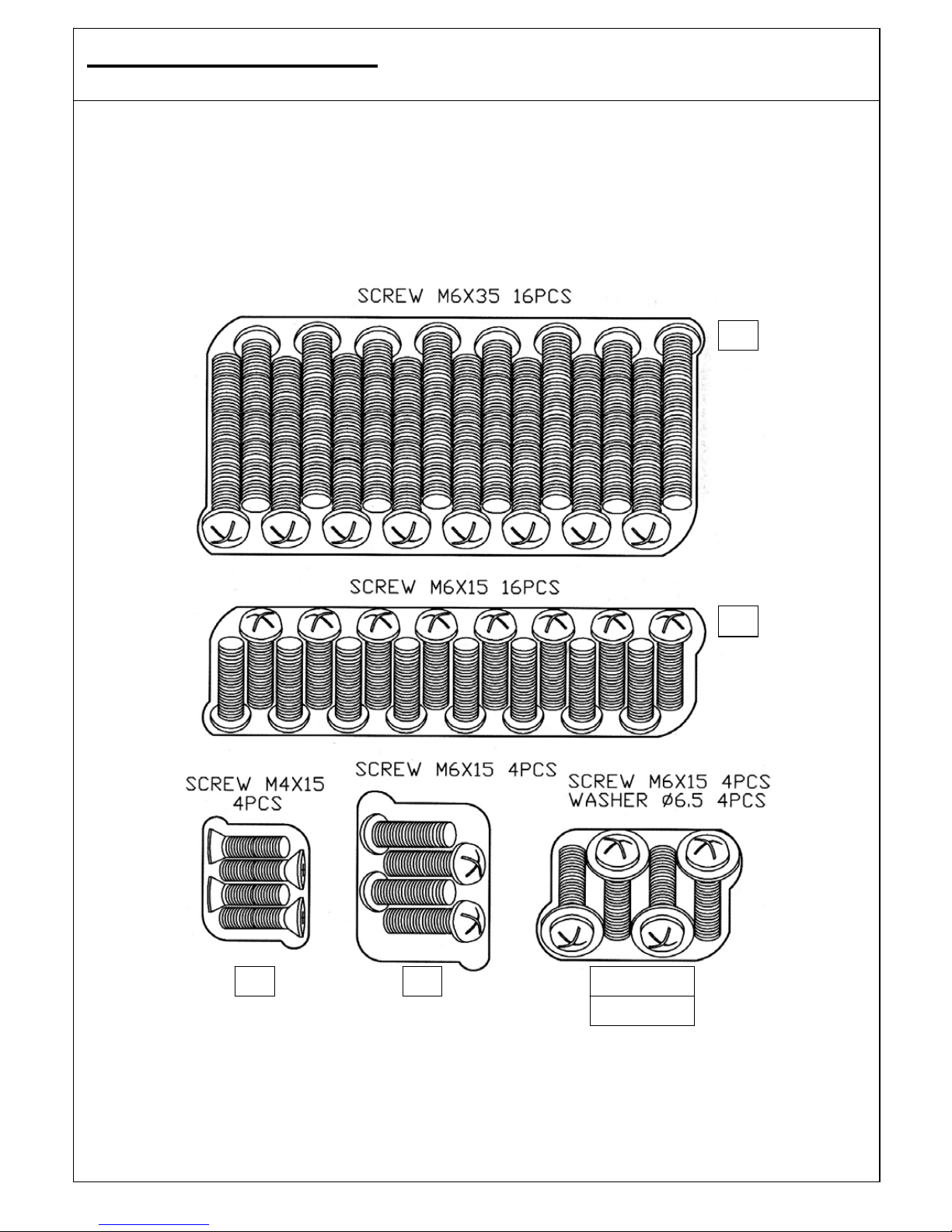
Hardw are Refer ence Diag ram
Specifications subject to change without prior notice.
D1
D2
D2 ( scr ew)
D3(washer)
D2
D4
Page 5
5
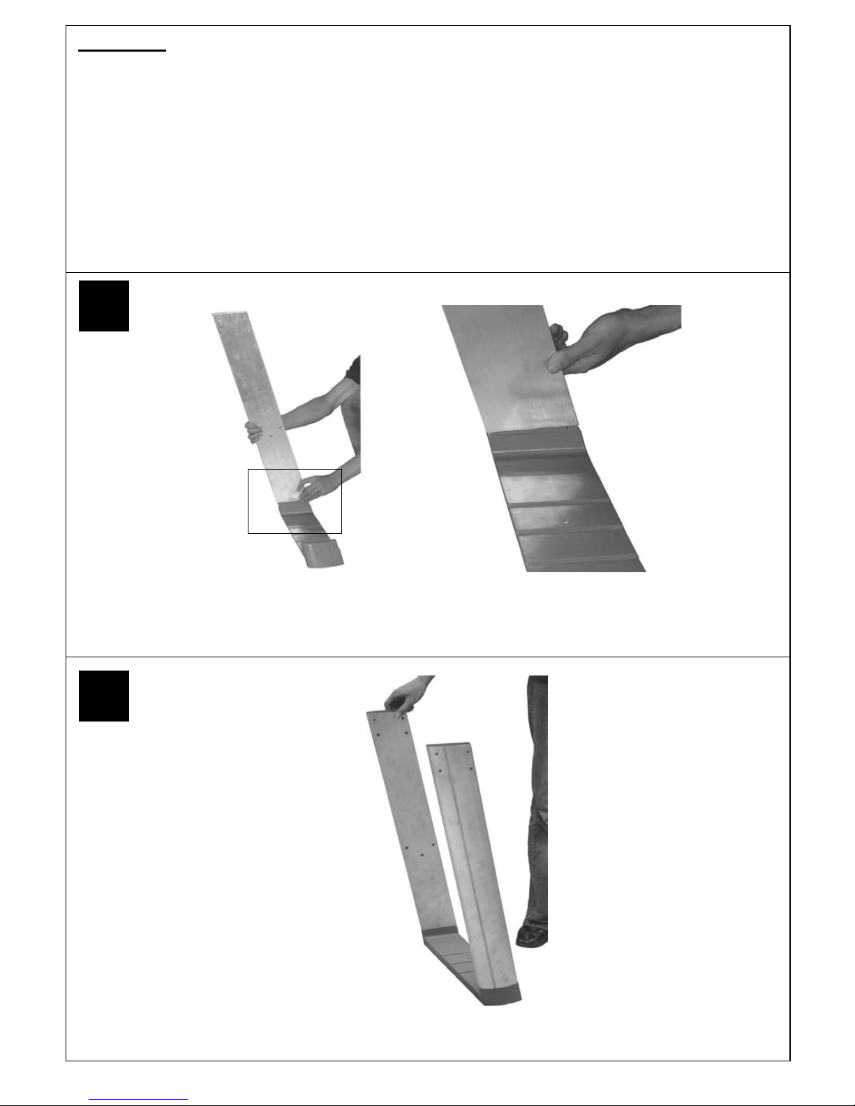
Attach the Rear Right Leg (C11) to the Trolley Foot (C15). T he legs are a push fit onto the trolley foot and
on the gas bottle holder. In case of difficulty, they may need tapping lightly with a soft face mallet. Take care
not to damage parts.
Attach the Front Right Leg (C10) to the Trolley Foot (C15)
Assembly
IMPORTANT!
•
Tools Required: Medium size flat blade or Phillips/Crosspoint screwdriver, adjustable spanner or metric
spanner set
•
The assembly of this barbecue requires 2 people.
•
Carefully unpack the trolley box and remove all internal packaging before commencing assembly.
•
Carefully remove the box lid from the body box and remove all internal packaging and parts inside the body.
•
The inlet connection of the gas rail assembly on the BBQ body is lower than the body. You must never allow
the pipe to rest on the ground during assembly as serious damage could result. We recommend the body is
left sitting in the box until required for assembly to trolley.
•
Whilst every care is taken in the manufacture of this product, care must be taken during assembly in case
sharp edges are present.
1
2
Page 6

6
Attach the Bottom Slat Assembly (C12) to the Base Tray (C13) using the Screws (D2).
Attach the leg assembly to the Base Tray (C13) using the Screws (D2).
4
3
Page 7
7
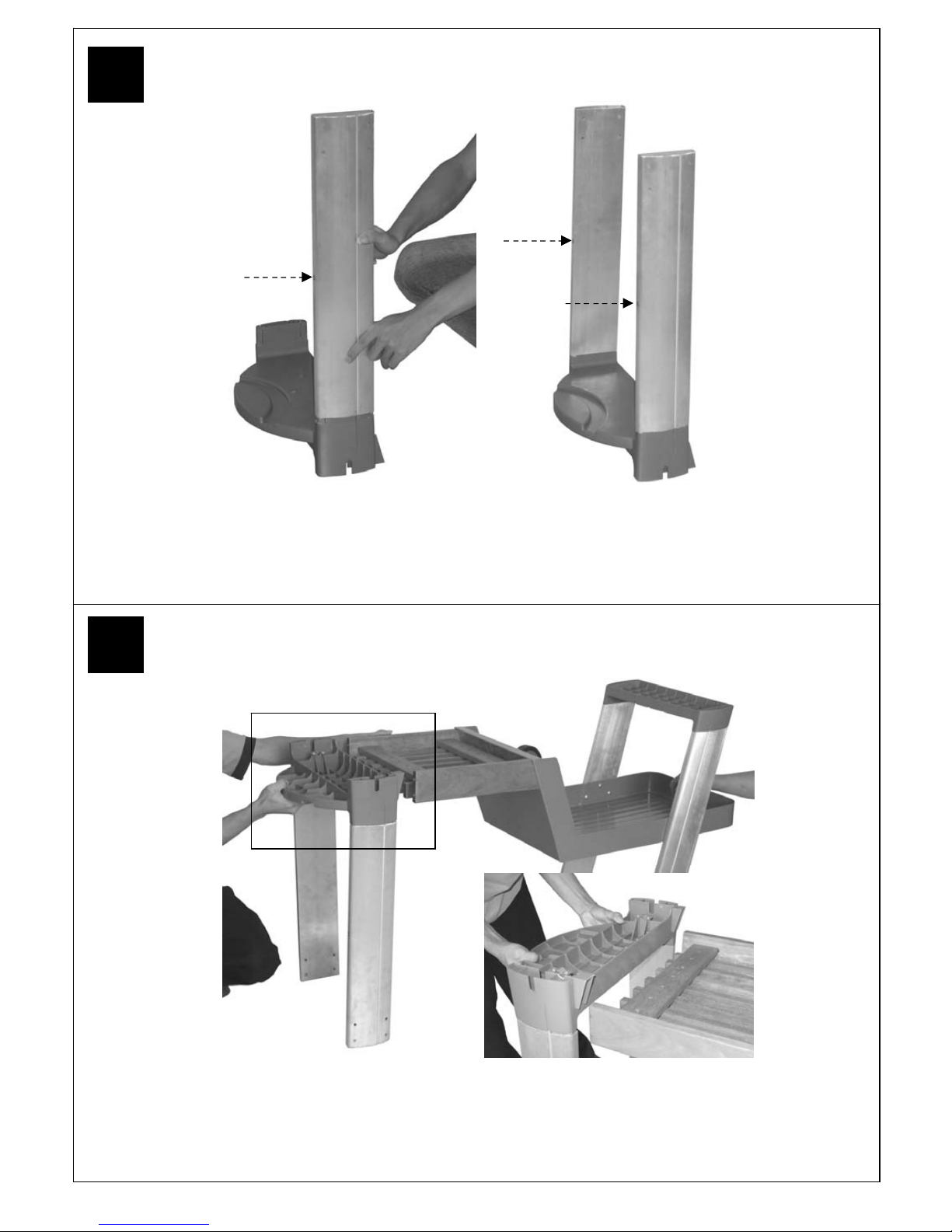
Align the Gas Bottle Holder (C14) with the Slat Assembly (C12).
Attach the Front Left Leg (C8) and Rear Left Leg (C9) to the Gas Bottle Holder (C14).
Note: Threaded inserts must be facing in the direction shown!
Threaded
Insert
6
5
Page 8

8
Attach the Gas Bottle Holder (C14) to the Bottom Slat Assembly (C12) using the Screws
(D2) and Washers (D3).
Insert t he axle ( C19) through t he clampi ng brackets o n the gas bot tle holder (C14) and
tighten the clamp screw s. Take care not to over tighten these screws which will damage
the plastic Gas Bott le Holder.
8
7
Page 9

9
Place the Wheels (C17) onto the Axle (C19) and secure with Locknuts (C18).
Carefully turn the completed trolley over, right side up.
10
9
Page 10

10
CAUTION! Care must be taken to ensure lid does not fall open
unexpectedly or that the lid surface is damaged when set on the ground.
Carefully turn the Barbecue Body (B1) upside down and remove the Drip Tray (B6). Attach the
R/H Side Shelf (C6) to the Barbecue Body (B1) using the Screws (D2).
Attach the Front Left Endcap (C3) to the Body (B1) using the Screws (D2).
12
11
Page 11

11
Attach the Rear Left Endcap (C4) to the Body (B1) using the Screws (D2).
CAUTION! Care must be taken to ensure lid does not fall open unexpectedly.
Carefully turn the Barbecue Body (B1) over right-side-up.
14
13
Page 12

12
Secure the Legs (C8), (C9), (C10), (C11) to the Endcaps (C3), (C4) and the R/H
Side Shelf (C6) using the Screws (D4).
Carefully lay the Barbecue Body (B1) onto the tops of the legs. The tops of the legs should slot into the
endcaps. When done correctly, the barbecue should be able to stand on its own weight.
WARNING: DO NOT RELEASE THE BARBECUE BODY WHILE THE BARBECUE HAS NOT BEEN
PROPERLY SEATED. THIS MAY RESULT IN INJURY OR DAMAGE TO YOUR BARBECUE.
16
15
Page 13

13
Attach the Side Shelf Shield (C2) to the endcaps
using the Countersunk Screws (D1).
Hook the L/H Side Shelf (C1) to the endcaps.
17 18
19 20
Lay the Utensil Trays (C5) into their positions on
either side of the barbecue body.
Place the Wheel Hubcaps (C16) onto the sides of
the Wheels (C17)
Page 14

14
Slide the loops of the Gas Bottle Strap (21) onto the Retaining Rod (C20). Secure the Rod
(C20) to the trolley legs using the Screws (D2).
Ensure the strap is threaded through the buckle correctly. It must hold the gas bottle firmly in
place onto the barbecue.
Slide the Drip Tray (B6) into place underneath the barbecue body.
22
21
Page 15

15
Place the Foil Liner (B8) into the Drip Pan (B7) and slide into place.
Fit the Warming Rack (B14). Re move the plastic wrap fro m the Lava Rock Baskets (B9) and lay the m
carefully into the body ensuring that they lie level within the body. Lay the Grills (B11) (B12) and Griddle
(B13) into place.
2 Burner: Left half - Grill w/cutout, Rock Basket; Right half - Grill w/cutout, Rock Basket
3/6 Burner: Left third - Grill w/cutout, Rock Basket Middle third - Grill, Rock Basket; Right third - Griddle
24
23
Page 16

16
Assembly is now complete.
All joints and connections must now be leak tested before using the barbecue.
For details of leak testing, please refer to instructions on Page 19.
Number of valves to be leak tested will vary with model of barbecue.
Connect the gas hose (B15) to the BBQ. Ensure the mating faces of the connection are clean and not
damaged. Do not use any sealing tape, paste, or liquid on the joint. T he nut must be tightened with the
use of a spanner. Do not use force which may damage the assembly.
26
25
Page 17

17
n
ESSENTIAL INF ORMATION
Please read instructions before using your barbecue.
BEFORE YOU USE YOUR BARBE CUE (also see installation)
•
Perform a leak test. This is the only safe and sure way to detect any gas leaking from joints and
connections of the barbecue after assembly. Follow the leak test instructions on page 19. Check that the
gas hose is free of any tension, twisting, cuts, or cracks.
•
Make sure your barbecue is in a safe place. It must be outdoors, on level ground and not below ground
level. Ensure that the barbecue is at least 1 metre away from any flammable materials, including trees and
fences and that there are no heat sources near the barbecue (cigarettes, open flames, spark etc.)
•
Check that you have the correct gas bottle and regulator for your barbecue (see recommendations in the
Gas and Regulator section of this manual) and that the gas bottle is placed correctly in the gas bottle holder
provided. Never place the gas bottle directly underneath the barbecue.
GETTING STARTED (also see operation)
•
Open the lid of your barbecue. Never light your barbecue with the lid closed. Turn the gas regulator or gas
bottle valve to the ‘on’ position. Push in the control knob of the burner you want to light and turn it anti
clockwise until resistance is felt. Wait 4 seconds and then continue turning the control knob until a click is
heard. Repeat if necessary until the burner is alight. Light all other burners in the same way making sure
each burner is alight before attempting to light the next. IF ANY BURNER FAILS T O LIGHT, TURN OFF
THE GAS AT T HE BURNERS AND THE GAS BOTT LE, WAIT FIVE MINUTES AND T RY AGAIN. If the
burners cannot be lit using the ignition system, turn to the manual lighting instructions under important
information.
•
Once the burners are lit, turn all the burners to the high setting for 3-5 minutes to pre-heat the barbecue.
This should be done before each session. When pre-heating is complete, cooking can begin taking extra
care if the burners are used in the high position.
•
To prevent food sticking we recommend that you use a long handled brush to apply a light coat of cooking
oil to the grills and griddles before each barbecue session.
•
Flare-ups may occur during cooking and can be controlled by applying salt directly onto the lava rock
making sure your hands are protected from the heat.
•
If a fat fire should occur during cooking, and if safe to do so, turn off the burners and the gas at the gas
bottle and wait for the fire to go out. Do not pull out the drip tray or douse with water.
•
Never douse a barbecue with water.
•
Never move a barbecue when lit.
•
Never leave a lit barbecue unattended
•
Never handle hot parts with unprotected hands
•
Keep children, animals, and elderly people a safe distance from a lit barbecue.
WHEN YOU HAVE FINISHED COOKING (also see Maintenance)
•
Turn all the burners to the high position for 3 to 5 minutes to burn off any food residue fro m the cooking
surfaces and burners. When the barbecue has cooled, the burnt residue can be easily re moved using a
damp, non abrasive cloth on the cooking surfaces and a wire brush on the burners. Never use any abrasive
material on porcelain finishes. The grills and griddles are not dishwasher safe.
•
We do not recommend washing lava rock, the step described above should remove most food residue from
the lava rock.
•
When the barbecue has cooled, scrape away any food and fat residue from the drip tray and discard.
Empty and clean the Foil Liner. These routines must be completed after each session.
STORAGE
•
Ensure the barbecue is properly cooled.
•
Always disconnect the gas bottle and store it in a safe place, never store a gas bottle indoors or on its side.
•
Store the barbecue in a cool dry place. T he detachable side shelf can be removed to save space during
Page 18

18
storage.
•
Cover the burners with foil to keep the burner holes free from insects or other debris.
•
If you intend to leave your barbecue outside make sure it is protected from the elements by a heavy duty
cover, these are available from most Outback® stockists.
•
Even when your barbecue is covered for its protection, it must be inspected on a regular basis as damp or
condensation can form which may result in damage to the barbecue. It may be necessary to dry the
barbecue and the inside of the cover. Any rust that is foun d that d oes not co me into cont act with the food
should be treated with a rust inhibitor and painted with barbecue paint or a heat resistant paint. Wooden
parts may also need to be cleaned and treated. Chrome plated warming racks etc. should be coated with
cooking oil. Wrap the burners in alu minium foil to help prevent insects or other debris fro m obstructing the
burners.
•
The gas bottle must be always be disconnected from the barbecue and stored in a well ventilated area at
least 1 metre away from any fi xed ignition source. Do not store inside residential accommodation. Never
store cylinders below ground level (e.g. cellars). Do not let children tamper with bottles.
IMPORTA NT INF ORMATION
•
This product is for outdoor use only. Do not use indoors. Do not use below ground level.
•
Do not store Gas bottles below ground level. LP gas is heavier than air so if a leak occurs the gas will
collect at a low level and could ignite in the presence of a flame or spark.
•
Do not store or use LP gas bottles on their side as this could allow liquid gas into the supply pipes with
serious results.
•
Leak test your barbecue annually. Check the hose connections are tight and leak test each time you
reconnect the gas bottle.
•
Always turn off the gas at the gas bottle when not in use.
•
Do not use aerosols near this barbecue.
GAS, REG ULATOR AND HOSE
This barbecue, hose, (and regulator, if included), are approved for use in the UK. The barbecue is also
approved for use in other countries as listed on the control panel and in the Technical Specifications included in
the barbecue manual. If the barbecue is intended to be used outside of the UK, the consumer MUST seek
advice from the local qualified gas supplier as to the suitability of the barbecue and with regards to the correct
hose and regulator that they should be using.
This barbecue can run on propane or butane LPG (liquid petroleum gas) bottled gas. For optimal performance
we recommend the use of propane gas which is supplied under a number of different names and bottle colours.
Butane gas can be used but it may restrict the heat output available from the burners, particularly when the gas
temperature falls below +10 degrees Celsius. If in doubt, please consult your gas dealer/distributor.
For optimal performance, we suggest the following:
Suitable regulator:
Butane – outlet pressure 28-30mbar
Propane – outlet pressure 37mbar The use of an adjustable regulator is dangerous and must never be used
with this barbecue.
Hose
•
Check that the gas hose does not touch any part of the barbecue that may become hot during operation.
MODEL BUTANE
MINI MUM
BOTTL E SI Z E
PROPANE
MINI MUM
BOTTL E SI Z E
2 BURNERS 13kg 6kg
3 BURNERS x 10kg
6 BURNERS x 10kg
Page 19

19
•
If the hose shows any sign of da mage it must be replaced with a hose that is suitable for use with LPG
(liquid petroleum gas) and meets British Standards.
•
The length of hose should not exceed 1.5 metres.
Please note
: the date on UK orange hose is the date of manufacture – not the expiry date
You must have the correct gas bottle, regulator, and hose for the barbecue to operate safely and
efficiently. Use of an incorrect or faulty regulator is dangerous and will invalidate the warranty on this
product. If you are unsure, please check with your local gas dealer.
INSTALLATION
Precautions:
•
Only use this barbecue in a well-ventilated outdoor area.
•
Check that the barbecue is not placed UNDER any combustible surface.
•
The sides of the barbecue should never be closer than 1 metre to any combustible material.
•
Do not obstruct any ventilation openings in the barbecue body.
•
Confirm all control knobs are in the off position before connecting the regulator.
•
Always connect the regulator in accordance with the regulator and gas bottle suppliers instructions.
LEAK TESTING
Always perform a leak test in a well-ventilated area.
Step 1 - Confirm all control knobs are in the off position.
Step 2 - Detach the barbecue control panel located across the front of the barbecue body by pulling off the
control knobs and removing the control panel retaining screws.
Step 3 - Turn on the gas at the gas bottle or regulator.
Step 4 - Check for leaks by brushing a solution of ½ water and ½ liquid soap over all the gas system joints,
including all valve connections, hose connections, and regulator connections.
Step 5 - If bubbles form over any of the joints there is a leak
•
Turn off the gas
•
Retighten all joints
•
Repeat test
•
If bubbles form again do not use the barbecue and contact your local Outback dealer for assistance or
call Outback customer services on (01622) 671771. Customer services are available during normal
office hours, Monday to Friday, 9am to 5pm.
OPERATION
Your barbecue is not designed to be used with more than 50% of the cooking area as a solid plate – this
includes baking dishes. If more than 50% of your cooking area is covered by a solid cooking surface, the
barbecue could overheat causing damage that is not covered by warranty.
Grill cooking
The cast iron burners heat the lava rock beneath the grill that, in turn, heats the food. The natural juices
produced during cooking fall onto the lava rock and vaporise to form smoke. The smoke then rises and ‘bastes’
the food, giving it that unique barbecued flavour.
Do not attempt to cook with the lid closed. T his will result in severe damage to your barbecue. Ensure all
burners are turned off and the barbecue has cooled down before closing the lid.
Griddle plate cooking
The cast iron burners heat the griddle plate directly, which then cooks the food on contact. Griddle plates
enable the cooking of smaller items that would, otherwise, fall through the grill. They can also be used for
searing cuts of meat or cooking food like eggs that would not be possible to cook on a grill. Griddles can also be
used to heat pans.
Warming Rack
Warming racks are a convenient way to keep cooked food warm or to warm items such as bread rolls. It is
advisable to place food to the front of the war ming rack to avoid the possibility of juices and fat running down
the back of your barbecue. Always check that your warming rack is properly fitted before use.
Page 20

20
Flare-up control
Flare-ups will often occur when food is barbecued as fat and juices fall onto the lava rock. Some fat is
necessary to give the food its barbecued flavour but excessive fat can result in a flare-up. T o avoid flare-ups it
is advisable to trim excess fat from meat and poultry before grilling, use cooking sauces and marinades
sparingly, and try to avoid very cheap cuts of meat or meat products as these tend to have high fat and water
contents. Flare-ups can be extinguished by applying salt directly onto the flaring lava rocks, taking care to
protect yourself from the flames.
Fat Fires
The Foil Liner must be emptied and the drip tray cleaned of food debris after each cooking session. If the
barbecue is to be used for commercial use or large gatherings, it will be necessary to turn off and cool the
barbecue every two hours to remove food debris from the drip tray and clean out the Foil Liner, the time
between cleaning may need to be reduced if very fatty foods or cheap meat products are being cooked. Failure
to do this may result in a fat fire, which may cause injury and could seriously damage the barbecue.
In the event of a fat fire;
•
If safe to do so, turn all control knobs to the ‘off’ position
•
Turn off the gas at the gas bottle
•
Keep everyone at a safe distance from the barbecue and wait until the fire has burnt out.
•
Do not close the lid of the barbecue.
•
NEVER DOUSE A BARBECUE WITH WATER. IF AN EXTINGUISHER IS USED, IT SHOULD BE A
POWDER TYPE.
•
DO NOT REMOVE THE DRIP TRAY
•
If the fire does not seem to be abating or appears to be worsening, contact your local Fire Brigade for
assistance.
Manual ignition instructions
•
Insert a long, lit match through the match-lighting hole in the right hand side of the body of the barbecue
until the lit end is alongside the right hand burner. Push and turn the right hand control knob anti-clockwise
to the high position taking care to protect yourself from flames.
•
When the burner is lit turn the remaining burners from right to left.
•
Confirm that each burner is lit before turning on the next burner
•
If the right hand burne r fails to light, turn off the gas and contact y our local Outback dealer or our
customer services department on (01622) 671771 for assistance.
MAINTENANCE
n
Never handle hot parts of the BBQ with unprotected hands.
n
Never douse the BBQ with water when its surfaces are hot.
General
•
Regularly clean your BBQ between uses and especially after extended periods of storage.
•
Do not leave the BBQ uncovered and exposed to the ele ments when not in use. Heavy duty covers are
available as an accessory from your Outback ® stockist. Even when your barbecue is covered for its
protection, it must be inspected on a regular basis as da mp or condensation can for m which may result in
damage to the barbecue. It may be necessary to dry the barbecue and the inside of the cover. Any rust that
is found that does not come into contact with the food should be treated with a rust inhibitor and painted with
barbecue paint or a heat resistant paint. Woode n parts may also need to be cleaned and treated. Chro me
plated warming racks etc. should be coated with cooking oil.
•
Lava rock can be cleaned by lighting the burners on full for 3 to 5 minutes. This should be done with the lid
in the raised position. Heavily impregnated lava rock should be turned over so that the dirty side faces the
burners in order to burn off any residue. We do not recommend washing lava rock.
•
The wooden shelf, shelf insert and bottom slats are made from hardwood ideally suited to outside
conditions. Hardwood will naturally weather and change its appearance and it is quite natural for small
cracks to appear on the surface of the wood. The wood should be regularly inspected and any weathered or
damaged surfaces should be recoated promptly with Yacht varnish or an external grade Polyurethane
varnish. Follow the varnish manufacturer’s instructions for preparation and application.
•
All screws and bolts should be checked and tightened if necessary on a regular basis.
Page 21

21
Burner removal
To remove the burners (see photos):
1. Remove the burner clip.
2. Lift the burner upwards.
3. Gently pull the burner mouth away from the valve injector.
4. Lift the burner out.
To re-install the burners (not depicted):
1. Slide the burner mouth over the valve injector. The injector should sit centrally within the burner venturi tube.
2. Lower the burner into the body.
3. Insert the locating stud through the support.
Lock into place by inserting the burner clip through the stud.
• Your burners have been preset for optimal flame perfor mance. You will normally see a blue flame, possibly
with a small yellow tip when the burner is alight. If the flame pattern is significantly yellow, this could be a
problem caused by grease from cooking blocking the burner or spiders or other insects in the burner venturi.
This can result in the flow of the gas and air mixture being restricted or blocked which may result in a fire
behind the control panel causing serious damage to your barbecue. If this happe ns, the gas should be
immediately turned off at the bottle.
• Burners should be inspected and cleaned on a regular basis in addition to the following conditions:
1. Bringing the barbecue out of storage.
2. One or more of the burners do not ignite.
3. The burner flame pattern is significantly yellow.
4. The gas ignites behind the control panel.
•
To clean a burner, remove it from the barbecue. It is quite normal for a cast iron burner to rust. The outside
of the burner can be cleaned with a wire brush.
•
Clean the portholes with a pipe cleaner or piece of wire. Take care not to enlarge the portholes.
•
Clean the insect screen on the end of the venturi tube with a bristle brush (i.e. an old toothbrush).
•
Clean the venturi tube with a pipe cleaner or piece of wire. You may need a torch to see into the venturi tube
to make sure it is clear. You will see a pin inside the tube which is part of the burner assembly.
•
Turn the burner up on end and lightly tap against a piece of wood to dislodge any debris from inside.
1
Injectors
2 3 4
Venturi tube
Page 22

22
Cleaning
Material Where used Cleaning Method Recommended
Porcelain Grills Enamel is a thin, glass based coating fused onto metal and
enamel Griddles as such needs to be treated with care. Cooking oil, together
with fat from food being cooked can turn to carbon as a
result of heating and result in black flakes coming away
from the cooking surfaces. These are not harmful.
Porcelain should be cleaned using hot soapy water or with
the use a suitable cleaning product following the
Manufactures instructions. Due to the weight of the grills
and griddle, we do not recommend cleaning in a
dishwasher.
Chromium Warming rack Wash with hot soapy water. A chrome cleaner may
plated be used if required. To prevent rusting, wipe with
cooking oil after rinsing and drying.
Wood Shelves and Wipe with a cloth wrung out in hot soapy water and dry.
shelf inserts
Plastic Trolley excluding Wipe with a cloth wrung out in hot soapy water and dry.
Paint wooden shelving Excess fat and food debris can be removed from inside the
Body body using a plastic or wooden scraper. Do not use
Utensil trays abrasives. If rust appears on the body it should be treated
with a suitable rust inhibitor and painted with a heat
resistant paint.
Galvanised Drip tray Excess fat and food debris must be removed using a
Foil Liner plastic or wooden scraper. This needs to be carried
out between each use of the BBQ. Excessive build
up is likely to lead to a fat fire which can be
hazardous and damage the BBQ. This is not a fault
in the BBQ and therefore is not covered by the
terms of the warranty.
If required, the tray and foil liner can be washed in
hot soapy water.
Cast Iron Burners Any food debris should be removed on a regular basis.
For detailed burner instructions refer to MAINTENANCE on
Page 20.
.
Page 23

23
Troubleshooting
Problem Possible Cause Solution
Bu rn ers wil l no t li gh t LP gas bottle is empty Replace with full gas bottle
using the ignition system
Faulty regulator Have regulator checked or replace
Obstructions in burners Clean burners
Obstructions in gas jets Clean jets and gas hose
or gas hose
Electrode wire is loose or Reconnect wire
disconnected on electrode
or ignition unit
Electrode or wire is damaged Change electrode and wire
Faulty integral igniter Replace gas valve complete
with integral igniter
Incorrect electrode gap/ The gas collector box around the
Ben t co ll ec to r box e le ct ro de eed s to be in lin e wi th the
burner with a gap of 3 to 4mm
between the end of the electrode
and the tag on the end of the
collector box. Realign the collector
box as required.
Burner will not light LP gas bottle is empty Replace with full gas bottle
with a match
Faulty regulator Have regulator checked or replace
Obstructions in burners Clean burners
Obstructions in gas jets Clean jets and gas hose
or gas hose
Lo w fl a me or fl as hb ac k (f ir e LP gas bottle too small Use larger gas bottle
In bur n er tu b e - a hiss in g or
roarIng noise may be heard) Obstructions in burners Clean burners
Obstructions in gas jets Clean jets and gas hose
or gas hose
Windy conditions Use BBQ in a more sheltered
position
Gas val ve k no b di ff ic ul t Integral ignition system jammed Replace gas valve complete
to turn Gas valve jammed with integral igniter
Page 24

24
For ref er ence and corresponde nce, r ecor d your serial number here.
(See sticker on side of barbecue body.)
Serial No.
__________________
This number may be required when ordering spare parts or ac cessor ies.
A part r eference number may also be required where applicab le.
Model Name
CE
Approval
Heat Input Burners
Injector
Size
Gas /
Pressure
Outback®
Society /
Granite
0359
359BR128
9.5kW 2
Butane/
28-30mbar
Propane/
37mbar
Outback®
Manhattan /
Graphite
0359
359BR128
14.5kW 3
Outback®
Monarch /
Mercury
0359
359BR128
19.0kW 6 0.89
Countries of Use:
I
3+(28-30/37)
BE, CY, CZ, EE, FR, GR, IE, IS, IT, LV, LT, LU, PT, SK, ES, CH, GB
I
3B/P(30)
CY, CZ, DK, EE, FI, GR, LV, LT, LU, MT, NL, NO, SK, SI, SE, TR
I
3B/P(50)
AT, DE, HU, SK, CH
I
3B/P(36)
PL
1.12
Published Oct ober 2006’
Customer Service
Outback UK
Unit 2 F arleigh Hill
Tovil
Maidstone
Ken t
ME15 6RG
Tel: 01622 671771
Fax: 01622 673101
e-mail: customerserv ice@outbackuk.com
T ech nical Specificat ions
In the unlikely event t hat you exper ience proble ms wit h t his barbeque, ple ase cont act:
 Loading...