

Outback Meteor Select MT-H4430-3, Meteor Select MS4431 Assembly Manual
0359
Assembly and Operating Instructions for Outback®
Meteor Select 4 Burner Gas BBQ
Drawings are not to scale.
Specifications subject to change
without prior notice.
WARNING
• For outdoor use only. Not for commercial use.
• Read in structions be fore using th e appliance . Failure to fo llow instruct ions could
result in death, serious bodily injury, and/or property loss.
• Warning: accessible parts may be very hot. Keep young children and pets away.
• Do not move the appliance during use.
• Turn off the gas supply at the gas bottle after use.
• Any mod ificat ion of t he app lianc e, mi suse, or fail ure to fo llow the instr uct ions may
be dangerous and wil l invalidat e your w arranty. T his does not affect y our statut ory
rights.
• Retain these instructions for future reference.
• Leak te st annual ly , and whenev er the ga s bot tle i s r emo ved or r eplac ed. Ch eck t hat
the hose connections are tight and leak test each time you reconnect the gas bottle.
• For Flare-up control please refer to the ‘OPERATION’ section of this manual.
FOR YOUR SAFETY
If you smell gas:
1. Shut off gas to the appliance.
2. Extinguish any open flame.
3. Open barbecue lid or hood.
4. If odour continues, discontinue use and
contact your local de al er.
FOR YOUR SAFETY
1. Do not store or use petr ol or other flam mable
vapours or liquid s in t he vi cinity of this or any
other appliance.
2. A gas bottle not connected for use must not be
stored in the vicinity of this or any other
appliance.
MT-H4430-3

2
CODE PART QTY
Outback® Meteor Select 4
Burner Gas BBQ
HOOD
A1
Hood (Pre-Assembled to Body)
1
A2 Hood Handle 1
A3 Warming Rack 1
BODY
B1 Barbecue Body 1
B2 Burner 4
B3 Control Panel 1
B4 Knob 4
B5 Hose and Regulator Assembly 1
B6 Lava Rock 1
B7 Lava Rock Basket 1
B8 Cooking Grill 1
B9 Cooking Griddle 1
B10 Drip Tray Left Bracket 1
B11 Drip Tray Right Bracket 1
B12 Drip Tray 1
B13 Drip Pan 1
B14 Ignition Button 1
TROLLEY
C1 Side Bu rner Shelf 1
C2 Side Burner Shelf Panel 1
C3 Side Burner Grid 1
C4 Knob Bezel 1
C5 Side Burner Knob 1
C6 Side Burner 1
C7 Side Shelf 1
C8 Side Shelf Panel 1
C9 Left Front Leg 1
C10 Left Rear Leg 1
C11 Right Front Leg 1
C12 Right Rear Leg 1
C13 Upper Body Sup port 1
C14 Storage Box Handle 1
C15 Storage Box 1
C16 Front Panel 1
C17 Side Panel 4
C18 Bottom Panel 1
C19 Wheel 2
C20 Wheel Hubcap 2
C21 Axle 1
C22 Electronic Ignition Assembly 1
C23 Heat S hield 1
HARDWARE
D1 ST4.0x10 S c rew 30
D2 M4x10 Bolt 3
D3 M4 Step Bolt 4
D4 M6x15 Bolt 16
D5 M6x40 Bolt 16
D6 M6 Nut 12
D7 Locknut 2
Pre-Assembled Component
Quantity varie s according to model purchase d
Appearance, si z e, an d c ons tr uc t i on m ay differ according to m od el purc hased
Parts List
Quantity varies according to model purchased. Specifications subject to change without prior notice. For
more details on hardware, please see the corresponding ‘Hardware Reference Diagram’.
3
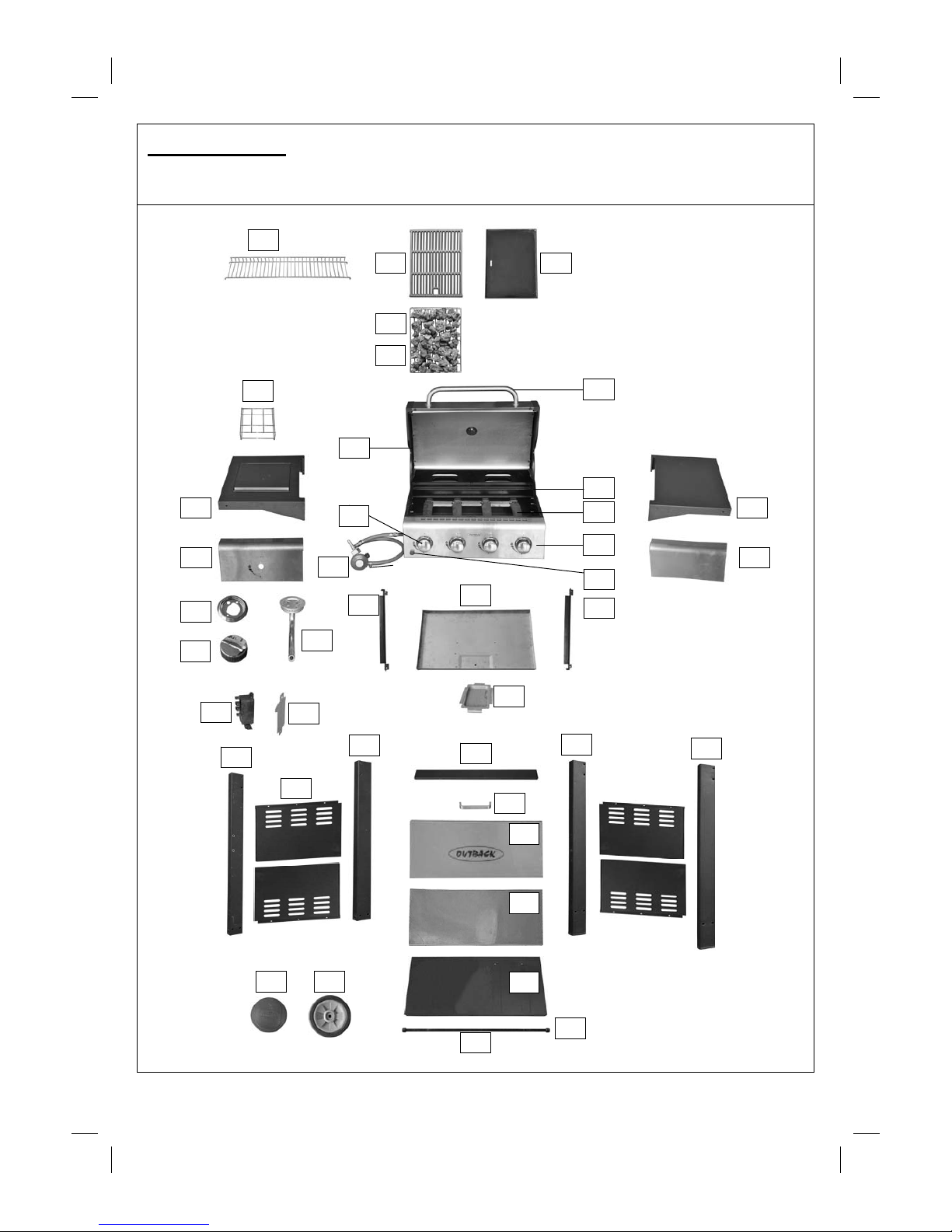
Parts Diagram
Quantity varies according to model purchased. Specifications subject to change without prior notice. For
more details on hardware, please see the corresponding ‘Hardware Reference Diagram’.
A2
A3
B1
B2
B4
B5
B6
B8
B10
B11
C1
C9
C17
C11
C13
C22
C23
C3
B14
C20
B9
B12
C18
C14
C21
B7
C8
C6
C2
C5
C4
C19
C15
C16
C12
B13
C10
B3
A1
C7
D7

4
Hardware Reference Diagram
Specifications subject to change without prior notice.
D1
D2
D3
D4
D5
D6
D4
D6
5
Assembly
IMPORTANT!
• TOOLS NEEDED FOR ASSEMBLY: Medium size flat blade or Phillips/Crosspoint screwdriver,
adjustable spanner or metric spanner set.
• Remove any internal component or packaging from the barbecue body.
• W hilst every care is taken in the manufacture of this product, care must be taken during assembly in
case sharp edges are present.
• Please read the Important Information section carefully before assembly and use of your
barbecue.
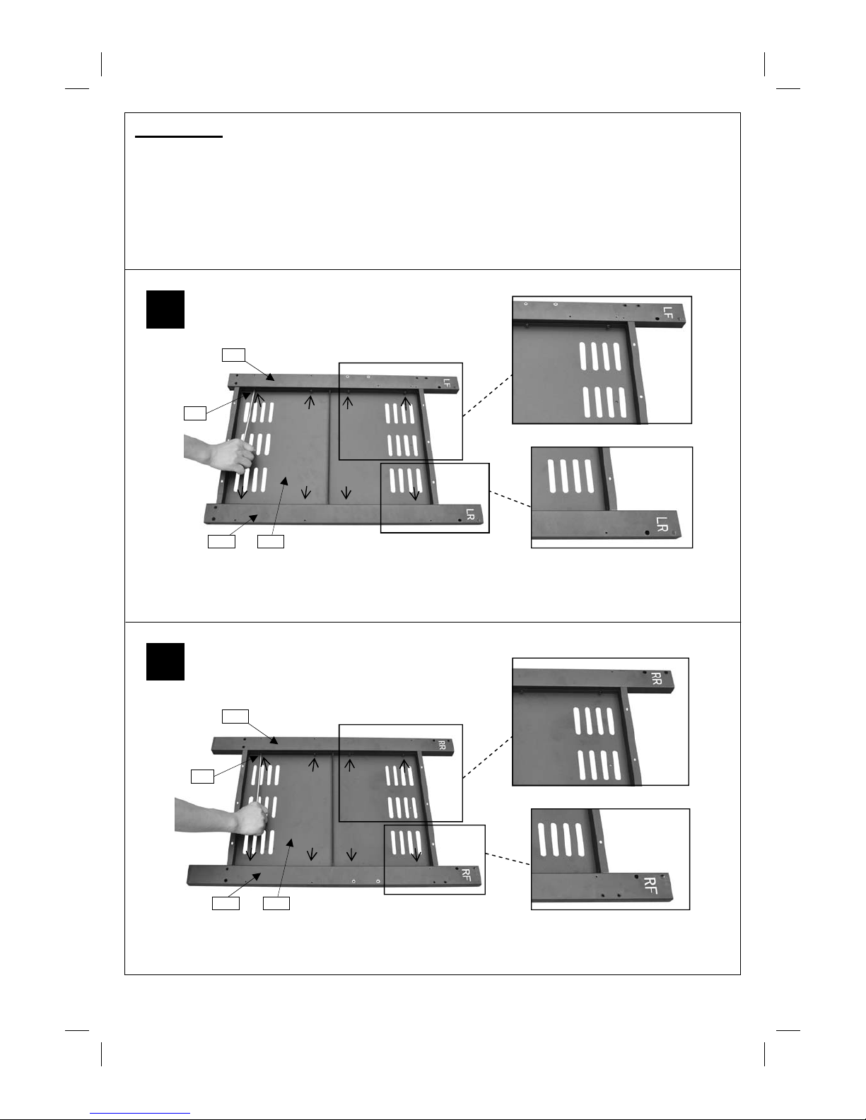
1
2
Attach the Left Legs (C9,C10) to the Side Panels (C17x2pcs) using ST4.0x10 Screws (D1x8pcs)
as shown.
Attach the Right Legs (C11,C12) to the Side Panels (C17x2pcs) using ST4.0x10 Screws (D1x8pcs)
as shown.
Left Ca binet Panel Assembly
Right Cabinet Panel Assembly
C9
C10
D1
C17
C12
C11
D1
C17
6
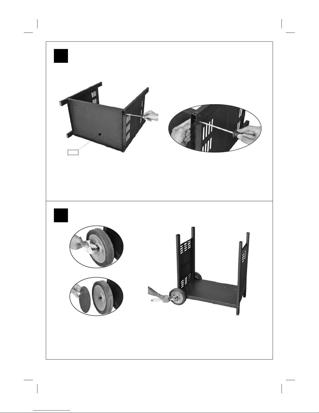
3
4
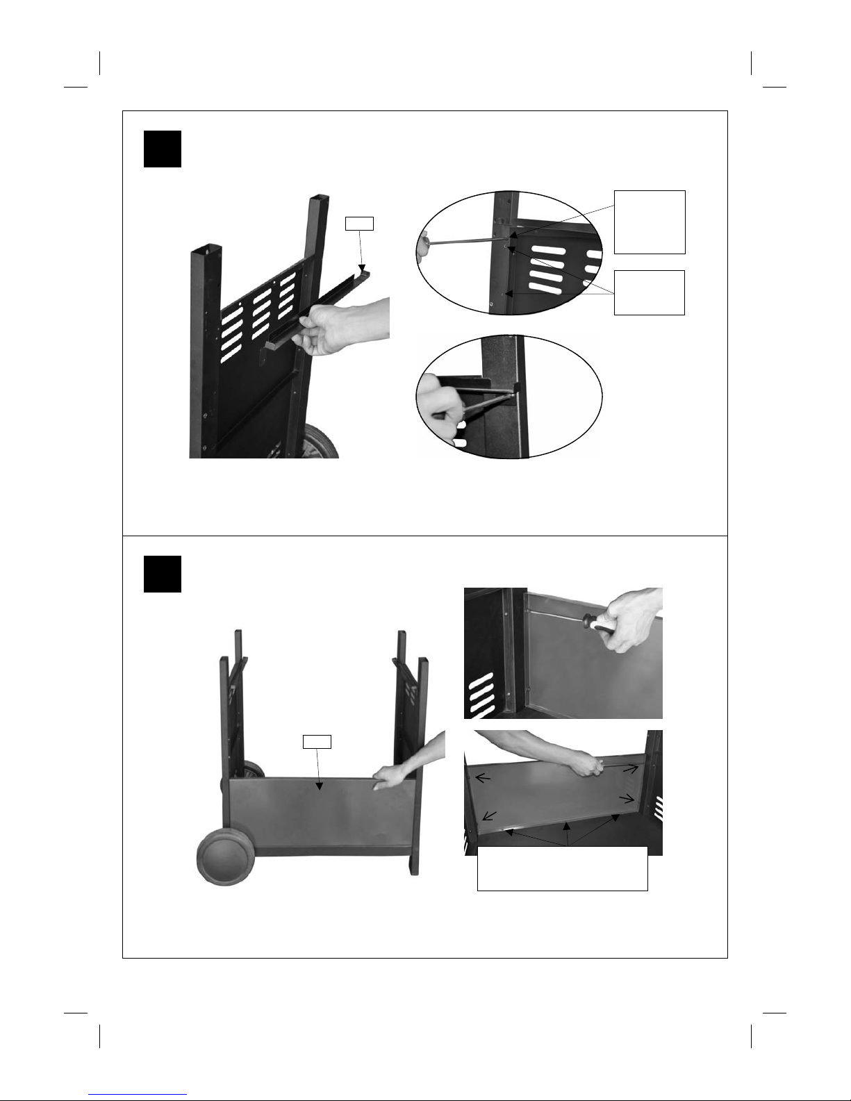
Attach the left / right cabinet panel assembly to the Bottom Panel (C18) using M6x40 Bolts
(D5x8pcs) and M6 Nuts (D6x8pcs) as shown.
Unscrew the Locknuts (D7) from both ends of the Axle (C21).
Slide the axle through t he corresponding holes in the lef t legs. Slide the W heels (C19) over eac h
end of the axle. Secure the w heels into place with the lo cknuts. Place the wheel Hubcaps (C20)
onto the outsides of the wheels.
C18
7
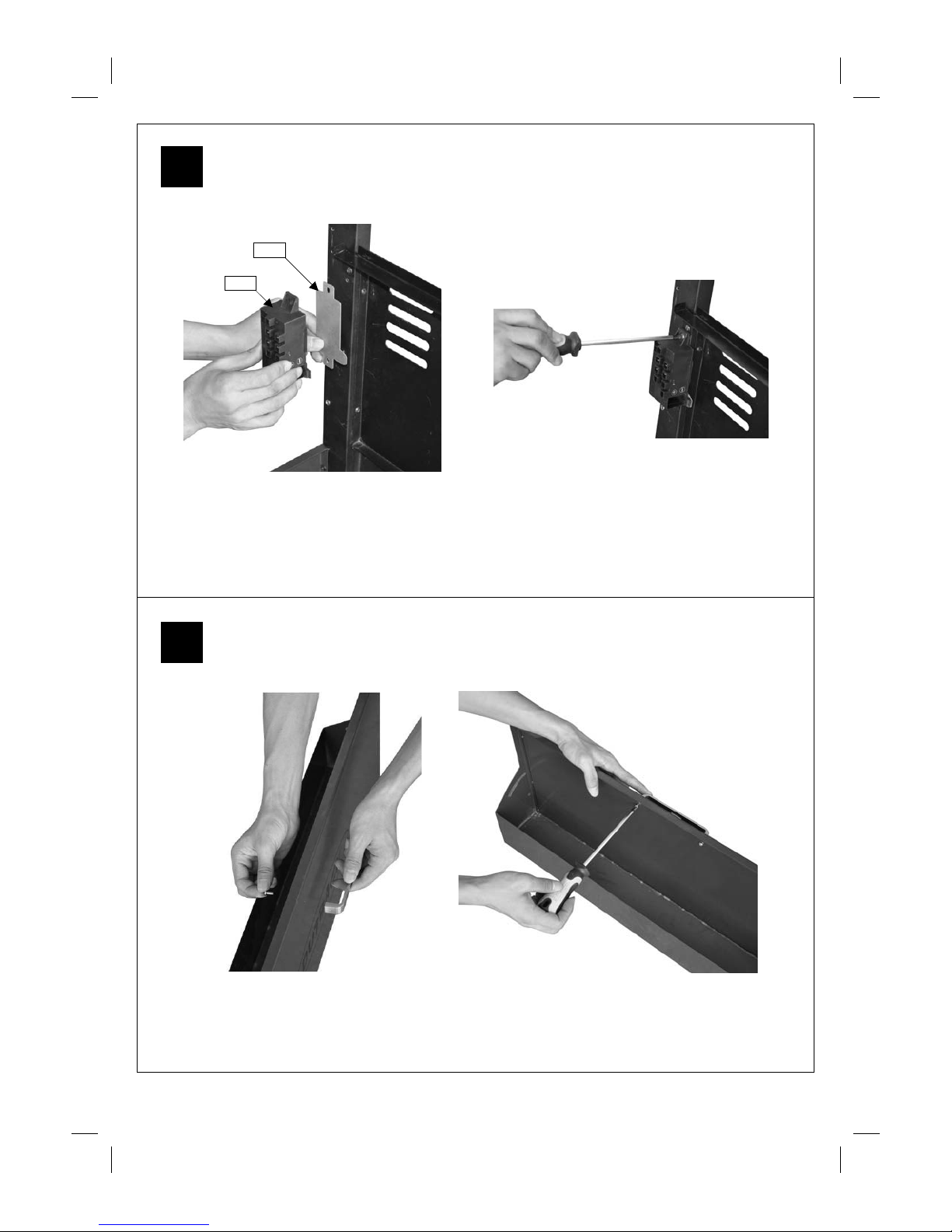
Attach Drip Tray Left Bracket (B10) to the right legs using ST4.0x10 Screws (D1x2pcs) as
shown. Repeat above process for Drip Tray Right Bracket (B11).
Install Front Panel (C16) between left / right front legs using ST4.0x10 Screws (D1x4pcs).
5
6
Front Side
Rear Side
Hole for
assembling
drip tray
bracket
Hole for
assembling
Ignition box
NOTE: Please Ignore Holes at
Base of Front Panel(C16) No
Screws are Required.
B10
C16
8
Fix the Electronic Ignition As sembly (C22) and Heat S hield (C23) to the front left leg by inserting
two ST4.0x10 Screws (D1x2pcs) through the electronic ignition assembly and heat shield and
screwing into the front left leg.
Remove the retaining bolts from Storage Box Handle (C14), and then attach it onto Storage Bo x
(C15) using the retaining bolts.
7
8
C23
C22
 Loading...