

Outback FXR2012A, VFXR2812A, VFXR3524A, FXR2524A, VFXR3648A Owner's Manual
...
FXR Series Inverter/Charger
FXR2012A FXR2524A FXR3048A
VFXR2812A VFXR3524A VFXR3648A
Operator’s Manual

About OutBack Power Technologies
OutBack Power Technologies is a leader in advanced energy conversion technology. OutBack products include true sine
wave inverter/chargers, maximum power point tracking charge controllers, and system communication components, as well
as circuit breakers, batteries, accessories, and assembled systems.
Grid/Hybrid™
As a leader in off-grid energy systems designed around energy storage, OutBack Power is an innovator in Grid/Hybrid system
technology, providing the best of both worlds: grid-tied system savings during normal or daylight operation, and off-grid
independence during peak energy times or in the event of a power outage or an emergency. Grid/Hybrid systems have the
intelligence, agility and interoperability to operate in multiple energy modes quickly, efficiently, and seamlessly, in order to
deliver clean, continuous and reliable power to residential and commercial users while maintaining grid stability.
Applicability
These instructions apply to OutBack inverter/charger models FXR2012A, FXR2524A, FXR3048A, VFXR2812A, VFXR3524A, and
VFXR3648A only.
Contact Information
Address: Corporate Headquarters
17825 – 59th Avenue N.E.
Suite B
Arlington, WA 98223 USA
Telephone:
Email: Support@outbackpower.com
Website: http://www.outbackpower.com
+1.360.435.6030
+1.360.618.4363 (Technical Support)
+1.360.435.6019 (Fax)
European Office
Hansastrasse 8
D-91126
Schwabach, Germany
+49.9122.79889.0
+49.9122.79889.21 (Fax)
Disclaimer
UNLESS SPECIFICALLY AGREED TO IN WRITING, OUTBACK POWER TECHNOLOGIES:
(a) MAKES NO WARRANTY AS TO THE ACCURACY, SUFFICIENCY OR SUITABILITY OF ANY TECHNICAL OR OTHER
INFORMATION PROVIDED IN ITS MANUALS OR OTHER DOCUMENTATION.
(b) ASSUMES NO RESPONSIBILITY OR LIABILITY FOR LOSS OR DAMAGE, WHETHER DIRECT, INDIRECT, CONSEQUENTIAL OR
INCIDENTAL, WHICH MIGHT ARISE OUT OF THE USE OF SUCH INFORMATION. THE USE OF ANY SUCH INFORMATION WILL BE
ENTIRELY AT THE USER’S RISK.
OutBack Power Technologies cannot be responsible for system failure, damages, or injury resulting from improper
installation of their products.
Information included in this manual is subject to change without notice.
Notice of Copyright
FXR Series Inverter/Charger Operator’s Manual © 2015 by OutBack Power Technologies. All Rights Reserved.
Trademarks
OutBack Power, the OutBack Power logo, FLEXpower ONE, Grid/Hybrid, and OPTICS RE are trademarks owned and used by
OutBack Power Technologies, Inc. The ALPHA logo and the phrase “member of the Alpha Group” are trademarks owned and
used by Alpha Technologies Inc. These trademarks may be registered in the United States and other countries.
Date and Revision
February 2015, Revision A (firmware revision 001.006.xxx)
Part Number
900-0167-01-00 Rev A

Table of Contents
Introduction .......................................................................................................... 7
Audience ................................................................................................................................................................................. 7
Symbols Used ........................................................................................................................................................................ 7
General Safety ....................................................................................................................................................................... 7
Welcome to OutBack Power Technologies ................................................................................................................. 8
Inverter Functions ................................................................................................................................................................ 8
Inverter Controls ................................................................................................................................................................... 9
MATE3 System Display and Controller ..................................................................................................................................... 9
On/Off Switch .................................................................................................................................................................................. 10
Commissioning .................................................................................................... 11
Functional Test ................................................................................................................................................................... 11
Pre-startup Procedures ................................................................................................................................................................ 11
Startup ............................................................................................................................................................................................... 11
Powering Down .............................................................................................................................................................................. 13
Adding New Devices ..................................................................................................................................................................... 13
Firmware Updates ......................................................................................................................................................................... 14
Operation ............................................................................................................ 15
LED Indicators ..................................................................................................................................................................... 15
Battery Indicators ........................................................................................................................................................................... 15
Status Indicators ............................................................................................................................................................................. 16
Inverter Functionality ...................................................................................................................................................... 17
AC Input Connection ....................................................................................................................................................... 17
Description of AC Input Modes .................................................................................................................................... 17
Generator .......................................................................................................................................................................................... 18
Support .............................................................................................................................................................................................. 18
Grid Tied ............................................................................................................................................................................................ 19
Grid Interface Protection Menu .................................................................................................................................................................... 20
Frequency and Phase Coordination ............................................................................................................................................................ 21
UPS ...................................................................................................................................................................................................... 21
Backup ............................................................................................................................................................................................... 22
Mini Grid ............................................................................................................................................................................................ 22
GridZero ............................................................................................................................................................................................ 23
Description of Inverter Operations ............................................................................................................................. 27
Inverting ............................................................................................................................................................................................ 27
DC and AC Voltages .......................................................................................................................................................................................... 27
AC Frequency ...................................................................................................................................................................................................... 28
Search ..................................................................................................................................................................................................................... 28
Input ................................................................................................................................................................................................... 29
AC Current Settings ........................................................................................................................................................................................... 30
AC Source Acceptance ..................................................................................................................................................................................... 30
Generator Input .................................................................................................................................................................................................. 32
Transfer .................................................................................................................................................................................................................. 32
Battery Charging ............................................................................................................................................................................ 33
Charge Current .................................................................................................................................................................................................... 33
Charge Cycle ........................................................................................................................................................................................................ 34
Advanced Battery Charging (ABC) ............................................................................................................................................................... 35
Charging Steps .................................................................................................................................................................................................... 35
New Charging Cycle .......................................................................................................................................................................................... 37
900-0167-01-00 Rev A 3

Table of Contents
Equalization .......................................................................................................................................................................................................... 40
Battery Temperature Compensation .......................................................................................................................................................... 41
Offset .................................................................................................................................................................................................. 42
Multiple-Inverter Installations (Stacking) ............................................................................................................................... 43
Stacking Configurations .............................................................................................................................................................. 44
Series Stacking (Dual-Stack) ........................................................................................................................................................................... 44
Parallel Stacking (Dual-Stack and Larger) ................................................................................................................................................. 44
Series/Parallel Stacking (Quad-Stack or Larger) ...................................................................................................................................... 45
Three-Phase Stacking ....................................................................................................................................................................................... 46
Power Save ........................................................................................................................................................................................................... 47
Auxiliary Terminals ........................................................................................................................................................................ 50
System Display-Based Functions ................................................................................................................................. 53
Advanced Generator Start (AGS) .............................................................................................................................................. 53
Grid Functions ................................................................................................................................................................................. 53
High Battery Transfer (HBX) ............................................................................................................................................................................ 53
Grid Use Time ...................................................................................................................................................................................................... 54
Load Grid Transfer ............................................................................................................................................................................................. 54
Metering ............................................................................................................. 55
MATE3 Screens ................................................................................................................................................................... 55
Inverter Screen ................................................................................................................................................................................ 55
Battery Screen ................................................................................................................................................................................. 56
Troubleshooting .................................................................................................. 57
Basic Troubleshooting ..................................................................................................................................................... 57
Error Messages ................................................................................................................................................................... 62
Warning Messages ............................................................................................................................................................ 63
Temperatures .................................................................................................................................................................................. 64
GT Warnings..................................................................................................................................................................................... 64
Disconnect Messages ...................................................................................................................................................... 65
Sell Status ............................................................................................................................................................................. 66
Specifications ...................................................................................................... 67
Electrical Specifications ................................................................................................................................................... 67
Mechanical Specifications .............................................................................................................................................. 70
Environmental Specifications ....................................................................................................................................... 70
Temperature Derating .................................................................................................................................................................. 70
Regulatory Specifications ............................................................................................................................................... 71
Listings ............................................................................................................................................................................................... 71
Certifications .................................................................................................................................................................................... 71
Compliance ...................................................................................................................................................................................... 71
FCC Information to the User .......................................................................................................................................................................... 71
Specification Compliance ............................................................................................................................................................................... 72
Summary of Operating Limits ....................................................................................................................................... 73
Limiting Charge Current (Multiple Inverters) ....................................................................................................................... 73
Firmware Revision ............................................................................................................................................................. 75
Default Settings and Ranges ......................................................................................................................................... 75
Definitions ............................................................................................................................................................................ 82
Index ................................................................................................................... 83
4 900-0167-01-00 Rev A

Table of Contents
List of Tables
Table 1 Battery Indicator Values .............................................................................................................................. 15
Table 2 Summary of Input Modes .......................................................................................................................... 25
Table 3 Charge Currents for FXR Models ............................................................................................................. 33
Table 4 Offset Interaction with AC Source ........................................................................................................... 42
Table 5 Aux Mode Functions .................................................................................................................................... 52
Table 6 Comparison of Grid Functions ................................................................................................................. 54
Table 7 Troubleshooting ............................................................................................................................................ 57
Table 8 Error Troubleshooting ................................................................................................................................. 62
Table 9 Warning Troubleshooting .......................................................................................................................... 63
Table 10 Inverter Temps ............................................................................................................................................... 64
Table 11 GT Warnings .................................................................................................................................................... 64
Table 12 Disconnect Troubleshooting .................................................................................................................... 65
Table 13 Sell Status Messages .................................................................................................................................... 66
Table 14 Electrical Specifications for 12-Volt FXR Models ................................................................................ 67
Table 15 Electrical Specifications for 24-Volt FXR Models ................................................................................ 68
Table 16 Electrical Specifications for 48-Volt FXR Models ................................................................................ 69
Table 17 Mechanical Specifications for FXR Models .......................................................................................... 70
Table 18 Environmental Specifications for all FXR Models .............................................................................. 70
Table 19 Interconnection Response Times to Abnormal Voltages or Frequencies ................................ 72
Table 20 Operating Limits for all FXR Models ....................................................................................................... 73
Table 21 Chargers On
Table 22 Charge Currents for Calculations ............................................................................................................ 75
Table 23 FXR Settings for 12-Volt Models .............................................................................................................. 76
Table 24 FXR Settings for 24-Volt Models .............................................................................................................. 78
Table 25 FXR Settings for 48-Volt Models .............................................................................................................. 80
Table 26 Terms and Definitions ................................................................................................................................. 82
and Current Settings .......................................................................................................... 74
900-0167-01-00 Rev A 5

Table of Contents
List of Figures
Figure 1 FXR Series Inverter/Charger with Turbo Fan .......................................................................................... 8
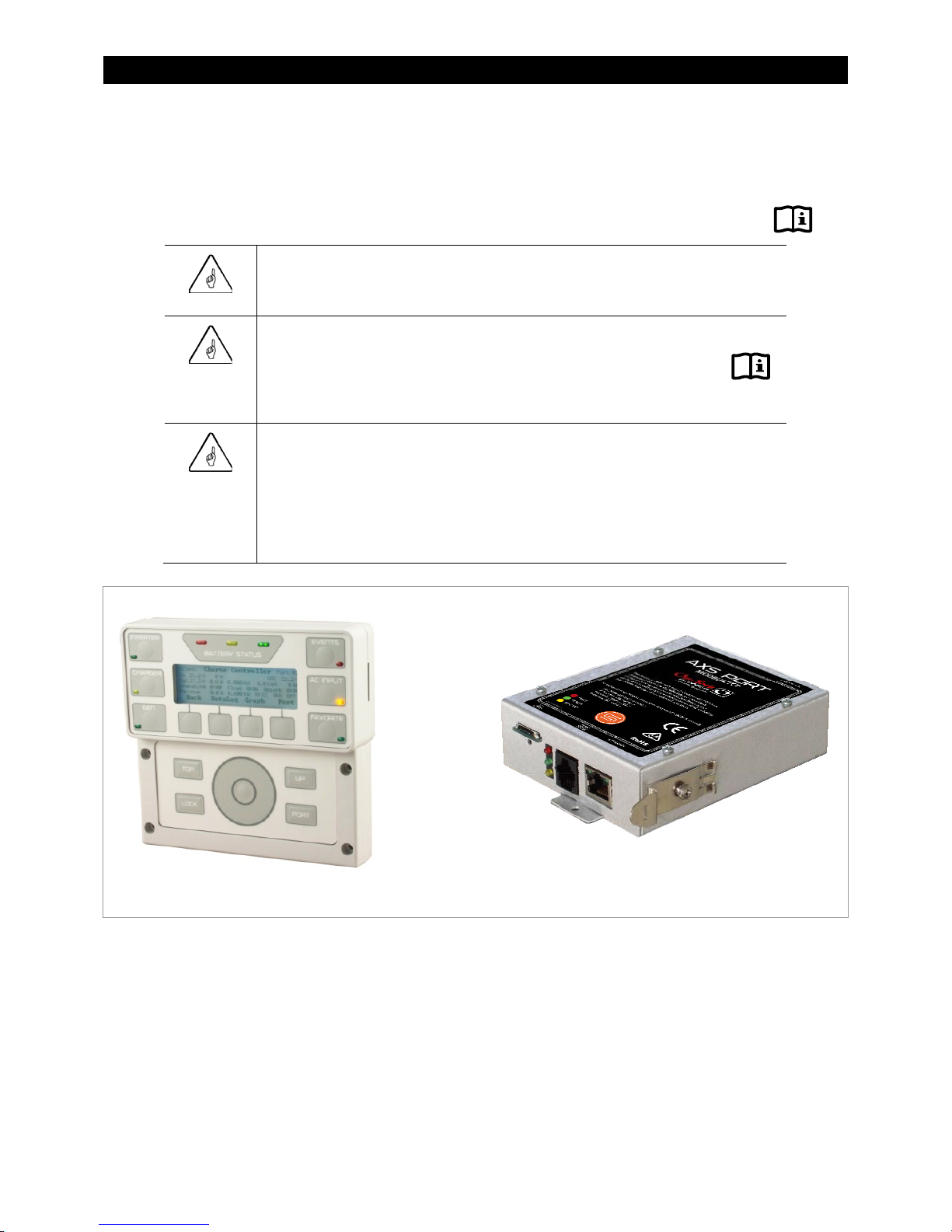
Figure 2 MATE3 and AXS Port .................................................................................................................................... 10
Figure 3 AC Terminals ................................................................................................................................................... 12
Figure 4 LED Indicators ................................................................................................................................................ 15
Figure 5 Inverter Status LED Indicators .................................................................................................................. 16
Figure 6 Charging Stages Over Time ....................................................................................................................... 34
Figure 7 Charging Stages Over Time (24/7) .......................................................................................................... 34
st
Figure 8 Repeated Charging (1
Figure 9 Repeated Charging (3
Figure 10 OutBack HUB10.3 and MATE3 .................................................................................................................. 43
Figure 11 Example of Series Stacking Arrangement ............................................................................................ 44
Figure 12 Example of Parallel Stacking Arrangement (Three Inverters) ....................................................... 45
Figure 13 Example of Series/Parallel Stacking Arrangement (Four Inverters) ............................................ 45
Figure 14 Example of Three-Phase Stacking Arrangement (Three Inverters) ............................................. 46
Figure 15 Example of Three-Phase Stacking Arrangement (Nine Inverters) ............................................... 46
Figure 16 Power Save Levels and Loads ................................................................................................................... 47
Figure 17 Power Save Priority (Parallel) .................................................................................................................... 49
Figure 18 Power Save Priority (Split-Phase) ............................................................................................................ 49
Figure 19 Home Screen .................................................................................................................................................. 55
Figure 20 Inverter Screens ............................................................................................................................................. 55
Figure 21 Battery Screen ................................................................................................................................................ 56
Figure 22 AC Test Points ................................................................................................................................................. 57
Figure 23 Temperature Derating ................................................................................................................................ 71
and 2nd Cycles) ................................................................................................. 38
rd
and 4th Cycles) ................................................................................................. 39
6 900-0167-01-00 Rev A
Introduction
Audience
This manual provides instructions for setup and operation of the product. It does not cover
installation. The manual is intended to be used by anyone required to operate the FXR Series
Inverter/Charger. Operators must be familiar with all the safety regulations pertaining to operating
power equipment of this type as required by local code. Operators are advised to have basic electrical
knowledge and a complete understanding of this equipment’s features and functions. Do not use this
product unless it has been installed by a qualified installer in accordance with the FXR Series
Inverter/Charger Installation Manual.
Symbols Used
WARNING: Hazard to Human Life
This type of notation indicates that the hazard could be harmful to human life.
CAUTION: Hazard to Equipment
This type of notation indicates that the hazard may cause damage to the equipment.
IMPORTANT:
This type of notation indicates that the information provided is important to the
installation, operation and/or maintenance of the equipment. Failure to follow the
recommendations in such a notation could result in voiding the equipment warranty.
MORE INFORMATION
When this symbol appears next to text, it means that more information is available in other manuals relating
to the subject. The most common reference is to the FXR Series Inverter/Charger Installation Manual. Another
common reference is the system display manual.
General Safety
WARNING: Limitations on Use
This equipment is NOT intended for use with life support equipment or other medical
equipment or devices.
WARNING: Reduced Protection
If this product is used in a manner not specified by FXR product literature, the product’s
internal safety protection may be impaired.
CAUTION: Equipment Damage
Only use components or accessories recommended or sold by OutBack Power
Technologies or its authorized agents.
900-0167-01-00 Rev A 7

Introduction
Welcome to OutBack Power Technologies
Thank you for purchasing the OutBack FXR Series Inverter/Charger. It is designed to offer a complete
power conversion system between batteries and AC power.
As part of an OutBack Grid/Hybrid™ system, it can provide off-grid power, grid backup power, or
grid-interactive service which sells excess renewable energy back to the utility.
Figure 1 FXR Series Inverter/Charger with Turbo Fan
Inverter Functions
Battery-to-AC inverting which delivers power to run backup loads and other functions
Provides single-phase output
Adjustable range of output voltage
Settable nominal output frequency
AC-to-battery charging (OutBack systems are battery-based)
Accepts a wide variety of single-phase AC sources
Uses battery energy stored from renewable resources
Can utilize stored energy from many sources (PV arrays, wind turbines, etc.)
OutBack FLEXmax charge controllers will optimize PV power production as part of a Grid/Hybrid system
Rapid transfer between AC source and inverter output with minimal delay time
8 900-0167-01-00 Rev A

Introduction
Uses the MATE3™ System Display and Controller or the AXS Port™ SunSpec Modbus Interface (sold
separately) for user interface as part of a Grid/Hybrid system
MATE3 must have firmware revision 003.002.xxx or higher
Supports the OPTICS RE™ online tool
Requires the MATE3 or the AXS Port
Visit www.outbackpower.com to download
Uses the HUB10.3™ Communications Manager for stacking as part of a Grid/Hybrid system
~ Stackable in series, parallel, series/parallel, and three-phase configurations
Listed to UL 1741 (2
Field-upgradeable firmware (from www.outbackpower.com); requires MATE3 or AXS Port
Seven selectable input modes for different applications
Generator
Support
Grid Tied (available in 24-volt and 48-models only)
UPS
Backup
Mini Grid
GridZero
Single AC input with dual input programming; individualized modes and priorities can be selected when
switching from utility grid to AC generator
external transfer device required
system display required for individual programming
: This product has a settable AC output range. In this book, many references to the output refer
NOTE
nd
Edition) and CSA 22.2 by ETL
to the entire range. However, some references are made to 120 Vac or 60 Hz output. These are
intended as examples only.
1
for a cloud-based remote monitoring and control application
Inverter Controls
The FXR inverter has no external controls. It can operate normally without an external control or
interface. Basic modes and settings are pre-programmed at the factory. (See the menu tables
beginning on page 76.) However, external communication devices such as the OutBack MATE3 or
AXS Port can be used to operate or program the inverter.
MATE3 System Display and Controller
The MATE3 System Display and Controller (sold separately) is designed to accommodate
programming and monitoring of a Grid/Hybrid power system. The MATE3 provides the means to
adjust the factory default settings to correctly match the installation where needed. It provides the
means to monitor system performance and troubleshoot fault or shutdown conditions. It also has
data logging and interface functions using the Internet.
Once settings are modified using a MATE3, the MATE3 can be removed from the installation. The
settings are stored in the nonvolatile memory of the FXR inverter. However, it is highly recommended
1
Outback Power Technologies Intuitive Control System for Renewable Energy
900-0167-01-00 Rev A 9
Introduction
to include a MATE3 as part of the system. This provides the means to monitor system performance
and respond quickly should it be necessary to correct a fault or shutdown condition.
The MATE3’s Configuration Wizard is capable of automatically configuring inverters to a series of
preset values. This is often more efficient than attempting to manually program each setting in each
inverter. Affected fields include system type, battery charging, and AC source configuration.
IMPORTANT:
The MATE3 system display must have firmware revision 003.002.xxx or higher.
IMPORTANT:
Some functions are not based in the inverter, but are part of the MATE3 firmware.
They will not function if the system display is removed. These functions are listed
beginning on page 53.
IMPORTANT:
The FXR inverter is only compatible with the MATE3 System Display and Controller.
It is not intended for use with the OutBack MATE or MATE2 products.
The FXR inverter can use the OPTICS RE online tool as a system display.
OPTICS RE must be used in conjunction with the MATE3 or with the AXS Port
SunSpec Modbus Interface.
On/Off Switch
If a system display is not in use, the inverter can be equipped with a switch to turn it on and off. This
switch is not sold as an inverter accessory; a common toggle switch can be used. The switch is wired
to the
INVERTER ON/OFF
for more information on wiring the switch.)
This switch turns only the inverter on and off. It does not turn the charger or any other function on or
off. All inverter functions will operate according to their programmed settings. Functions included
with a system display will not be available.
10 900-0167-01-00 Rev A
auxiliary terminals. (See the FXR Series Inverter/Charger Installation Manual
Figure 2 MATE3 and AXS Port
Commissioning
Functional Test
WARNING: Shock Hazard and Equipment Damage
The inverter’s AC and DC covers must be removed to perform these tests. The components are close
together and carry hazardous voltages. Use appropriate care to avoid the risk of electric shock or
equipment damage.
It is highly recommended that all applicable steps be performed in the following order. However, if
steps are inapplicable, they can be omitted.
If the results of any step do not match the description, see the Troubleshooting section on page 57.
Pre-startup Procedures
1. Ensure all DC and AC overcurrent devices are opened, disconnected, or turned off.
2. Double-check all wiring connections.
3. Confirm that the total load does not exceed the inverter’s rated power. (See page 27 and the
specifications tables beginning on page 67.)
4. Inspect the work area to ensure tools or debris have not been left inside.
5. Using a digital voltmeter (DVM) or standard voltmeter, verify battery voltage. Confirm the
voltage is correct for the inverter model. Confirm the polarity.
6. Connect the system display, if present.
CAUTION: Equipment Damage
Incorrect battery polarity will damage the inverter. Excessive battery voltage also may damage the inverter.
This damage is not covered by the warranty.
IMPORTANT:
Prior to programming (see Startup), verify the operating frequency of the AC source. This is necessary for
correct AC operation. The default setting is 60 Hz, but this can be changed to 50 Hz.
Startup
To start a single-inverter system:
1. Close the main DC circuit breakers (or connect the fuses) from the battery bank to the inverter.
Confirm that the system display is operational, if present.
900-0167-01-00 Rev A
11
Commissioning
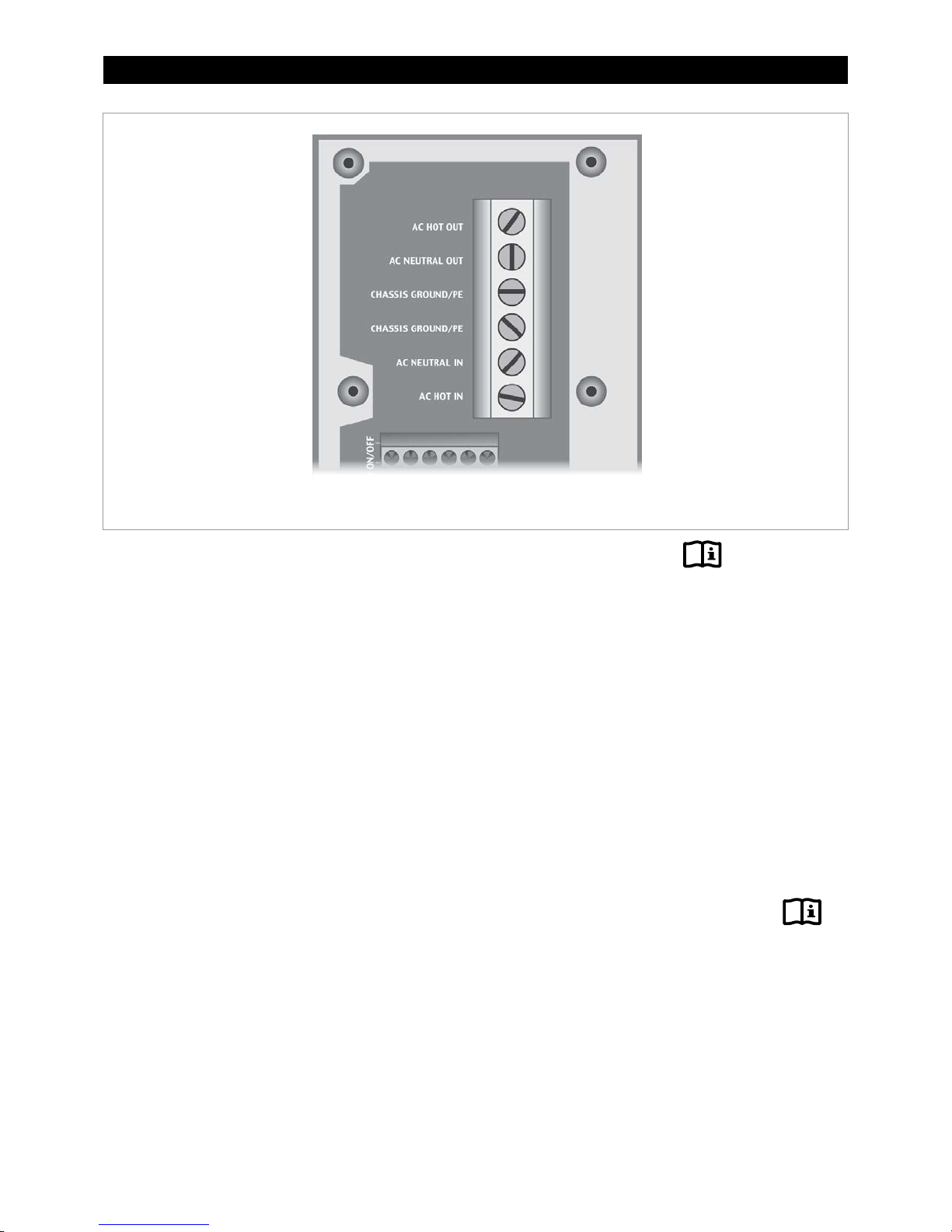
Figure 3 AC Terminals
2. If a system display is present, perform all programming for all functions.
These functions may include AC input modes, AC output voltage, input current limits, battery
charging, generator starting, and others.
AC input modes are described beginning on page 17 and are summarized on page 25. The
inverter’s individual operations are described beginning on page 27.
3. Turn on the inverter using the system display (or external switch, if one has been installed).
The inverter’s default condition is Off. Do not turn on any AC circuit breakers at this time.
4. Using a DVM or voltmeter, verify 120 Vac (or appropriate voltage) between the AC HOT OUT
and AC NEUTRAL OUT terminals. (See Figure 3 for AC terminals.) The inverter is working
correctly if the AC output reads within 10% of 120 Vac or the programmed output voltage.
5. Proceed past the items below to Step 6 on the next page.
To start a multiple-inverter (stacked) system:
1. Close the main DC circuit breakers (or connect the fuses) from the battery bank to the inverter.
Repeat for every inverter present. Confirm that the system display is operational.
With the system display, perform any programming for stacking and all other functions.
These functions may also include AC input modes, AC output voltage, input current limits,
battery charging, generator starting, and others. When stacking in parallel, all slave inverters will
observe the master programming settings. They do not need to be programmed individually.
The MATE3 Configuration Wizard may be used to assist programming.
AC input modes are described beginning on page 17 and are summarized on page 25. The
inverter’s individual operations are described beginning on page 27. Stacking is described
beginning on page 43.
2. Turn on the master inverter using the system display (or external switch, if one has been
installed). The inverter’s default state is Off. Do not turn on any AC circuit breakers at this time.
12 900-0167-01-00 Rev A

Commissioning
3. Using the system display, temporarily bring each slave out of Silent mode by raising the Power
Save Level of the master. (See page 47.)
As each slave is activated, it will click and create an audible hum.
Confirm that the system display shows no fault messages.
4. Using a DVM or voltmeter, verify appropriate voltage between the AC HOT OUT terminal on
the master inverter and the AC HOT OUT terminal on each slave. Series inverters should read
within 10% of 120 Vac or the programmed output voltage. Parallel inverters should read
close to zero. Three-phase inverters should read within 10% of 208 Vac or the designated
output voltage.
When this test is finished, return the master to its previous Power Save Level.
After output testing is completed, perform the following steps:
6. Close the AC output circuit breakers. If AC bypass switches are present, place them in the
normal (non-bypass) position. Do not connect an AC input source or close any AC input circuits.
7. Use a DVM to verify correct voltage at the AC load panel.
8. Connect a small AC load and test for proper functionality.
9. Close the AC input circuit breakers and connect an AC source.
Using a DVM or voltmeter, check the AC HOT IN and AC NEUTRAL IN terminals for 120 Vac (or
appropriate voltage) from the AC source.
If a system display is present, confirm that the inverter accepts the AC source as appropriate for its
programming. (Some modes or functions may restrict connection with the source. If one of these
selections has been used for the system, it may not connect.) Check the system display indicators
for correct performance.
10. If the charger is activated, the inverter will perform a battery charging cycle after powering up.
This can take several hours. If restarted after a temporary shutdown, the inverter may skip
most or all of the charging cycle. Confirm that it is charging as appropriate by using the
system display.
11. Test other functions which have been enabled, such as generator start, selling, or search mode.
12. Compare the DVM’s readings with the system display meter readings. If necessary, the system
display’s readings can be calibrated to match the DVM more accurately. Calibrated settings
include AC input voltage, AC output voltage, and battery voltage.
Powering Down
These steps will completely isolate the inverter.
To remove power from the system:
1. Turn off all load circuits and AC input sources.
2. Turn off all renewable energy circuits.
3. Turn each inverter OFF using the MATE3 system display or external switch.
4. Turn off the main DC overcurrent devices for each inverter.
Adding New Devices
When adding new devices to the system, first turn off the system according to the Power Down
instructions. After adding new devices, perform another functional test, including programming.
900-0167-01-00 Rev A 13
Commissioning
Firmware Updates
IMPORTANT:
All inverters will shut down during firmware updates. If loads need to be run while
updating the firmware, bypass the inverter with a maintenance bypass switch.
Communication cables must remain connected and DC power must remain on.
Interrupted communication will cause the update to fail and the inverter(s) may not work
afterward. Inverters automatically update one at a time beginning with the highest port.
Each requires about 5 minutes.
Updates to the inverter’s internal programming are periodically available at the OutBack website
www.outbackpower.com. If multiple inverters are used in a system, all units must be upgraded at the
same time. All units must be upgraded to the same firmware revision.
IMPORTANT:
All stacked FXR inverters must have the same firmware revision. If multiple stacked
inverters are used with different firmware revisions, any inverter with a revision different
from the master will not function. (See the stacking section on page 43.) The MATE3 will
display the following message:
An inverter firmware mismatch has been detected. Inverters X, Y, Z 2 are disabled. Visit
www.outbackpower.com for current inverter firmware.
NOTES:
2
The port designations for the mismatched inverters are listed here.
14
900-0167-01-00 Rev A
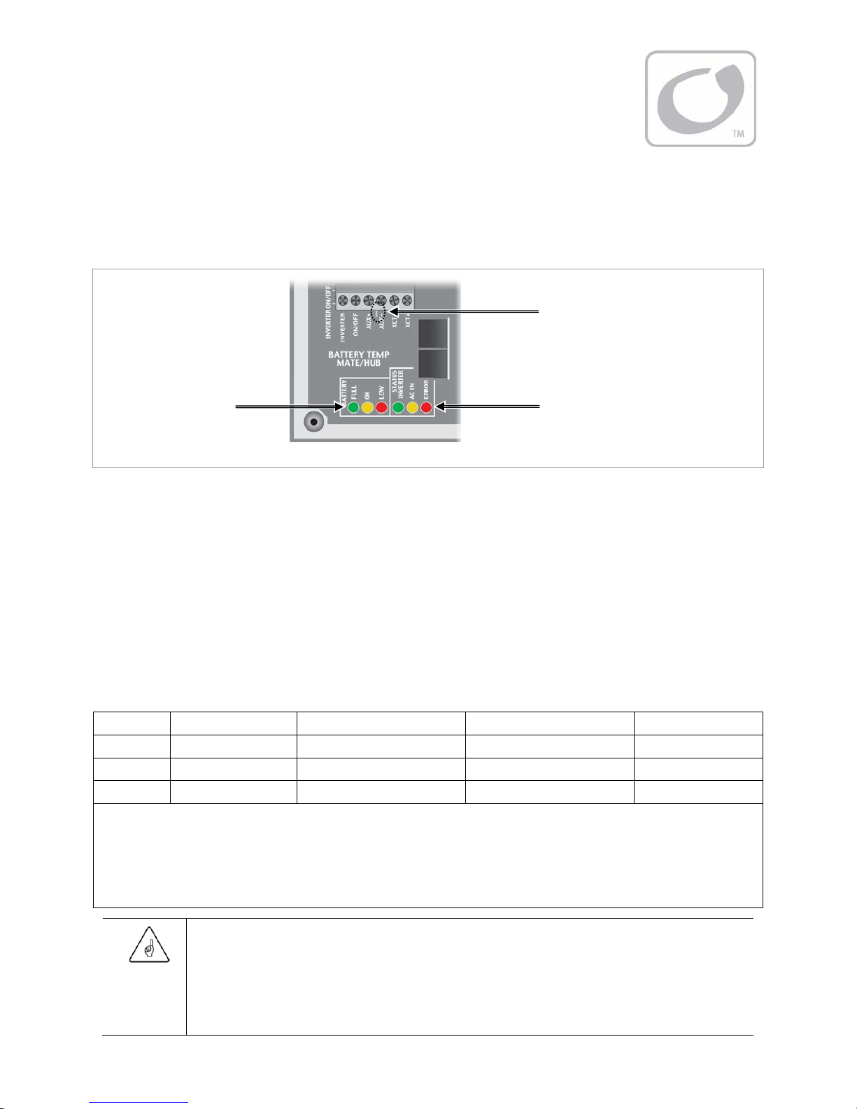
LED Indicators
Operation
AUX Indicator (see page 50)
Battery
Indicators
Status Indicators
Figure 4 LED Indicators
Battery Indicators
The Battery LED indicators show the approximate battery state. (See
Battery indicators and the Inverter Status indicators are independent. They may accompany each other
depending on conditions. Common combinations are noted on page 16.
A green indicator (FULL) means the batteries have an adequate charge at that time. It does not always mean
they are full. It may be accompanied by a yellow Status indicator when an AC source is charging.
A yellow indicator (OK) means the batteries are somewhat discharged.
A red indicator (LOW) means the batteries are greatly discharged and may require attention. It may be
accompanied by a red Status indicator to indicate a low battery error.
Color 12 Vdc Unit 24 Vdc Unit, ± 0.2 Vdc 48 Vdc Unit, ± 0.4 Vdc Battery Status
GREEN 12.5 Vdc or higher 25.0 Vdc or higher 50.0 Vdc or higher ACCEPTABLE
YELLOW 11.5 to 12.4 Vdc 23.0 to 24.8 Vdc 46.0 to 49.6 Vdc MARGINAL
RED 11.4 Vdc or lower 22.8 Vdc or lower 45.6 Vdc or lower LOW
IMPORTANT
Table 1 Battery Indicator Values
note below.) The
NOTES
900-0167-01-00 Rev A
:
Gaps in the table (higher-voltage units) are due to the resolution of the inverter’s DC meter.
These voltage settings are not the same as the Low Battery Cut-Out (LBCO) set point. (See page 27.) The Battery indicator
settings cannot be changed.
Voltages higher than shown in the GREEN row usually show that the batteries are charging.
IMPORTANT:
Due to different system states, battery voltage does not always indicate an accurate state of charge. It is
accurate if batteries have been at rest for several hours at room temperature (25°C or 77°F, or as specified
by the battery manufacturer). If they have
their voltage may not reflect their true state. The OutBack FLEXnet DC is a battery monitor that can be
added to the system to provide accurate measurements.
loads, a charging source, or are at another temperature,
any
15

Operation
Status Indicators
STATUS INVERTER (Green):
Solid: The FXR inverter is on and providing power.
If accompanied by a solid yellow
inverter is also connected to the utility grid with an AC input
mode that uses both inverter power and grid power
(
Support, Grid Tied
See page 17 for descriptions of AC input modes.
, or
GridZero
indicator (2), the
AC IN
).
Flashing: The inverter has been turned on but is idle.
The inverter is likely in Search mode. See page 28.
Off: The inverter is off. It is not waiting to provide power.
See Startup on page 11, or the system display manual, to turn
the inverter on.
Any power present is from another source such as the utility grid
or generator.
The inverter may also be a slave that is in Silent mode due to the
Power Save function. If so, the master inverter may still be
providing power to the system.
See page 47 for a description of Power Save.
AC IN (Yellow):
Solid: The AC source is connected and providing power.
The FXR inverter may or may not be charging the batteries, depending on settings.
May be accompanied by green
STATUS INVERTER
indicator (1).
Flashing: The AC source is present but has not been accepted.
If flashing continues, the FXR inverter is refusing the source. See the Troubleshooting section on page 57.
Off: No AC source is detected.
If a source is supposed to be present, see the Troubleshooting section on page 57.
ERROR (Red):
Solid: Error. The inverter has shut down due to a critical problem which may be internal or external.
This indicator is accompanied by an error message in the system display.
See page 62 for a description of error messages.
Flashing: Warning. The inverter has detected a non-critical problem but has not yet shut down.
A warning does not always lead to a shutdown — if it does, it becomes an error.
This indicator is accompanied by a warning message in the system display.
See page 63 for a description of warning messages.
Off: No problems are detected.
Figure 5 Inverter Status LED Indicators
16 900-0167-01-00 Rev A
Operation
T
Inverter Functionality
The FXR inverter can be used for many applications. Some of the inverter’s operations occur
automatically. Others are conditional or must be enabled manually before they will operate.
Most of the inverter’s individual operations and functions can be programmed using the system
display. This allows customization or fine tuning of the inverter’s performance.
Before operating the inverter:
The operator needs to define the application and decide which functions will be needed. The FXR
inverter is programmed with many AC input modes. Each mode has certain advantages which make it
ideal for a particular application. Some modes contain functions unique to that mode.
The modes are described in detail following this section. To help decide which mode will be used, the
basic points of each mode are compared in Table 2 on page 25.
Apart from the input modes, FXR inverters possess a set of common functions or operations. These
operations are described in detail beginning on page 27. Most of these items operate the same
regardless of which input mode is selected. The exceptions are noted where appropriate.
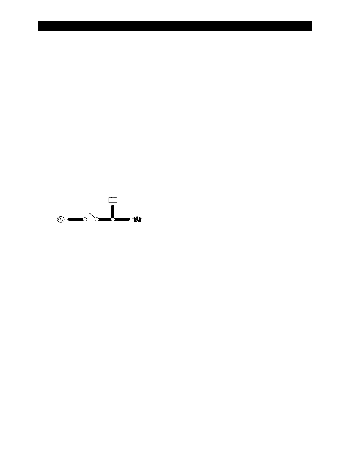
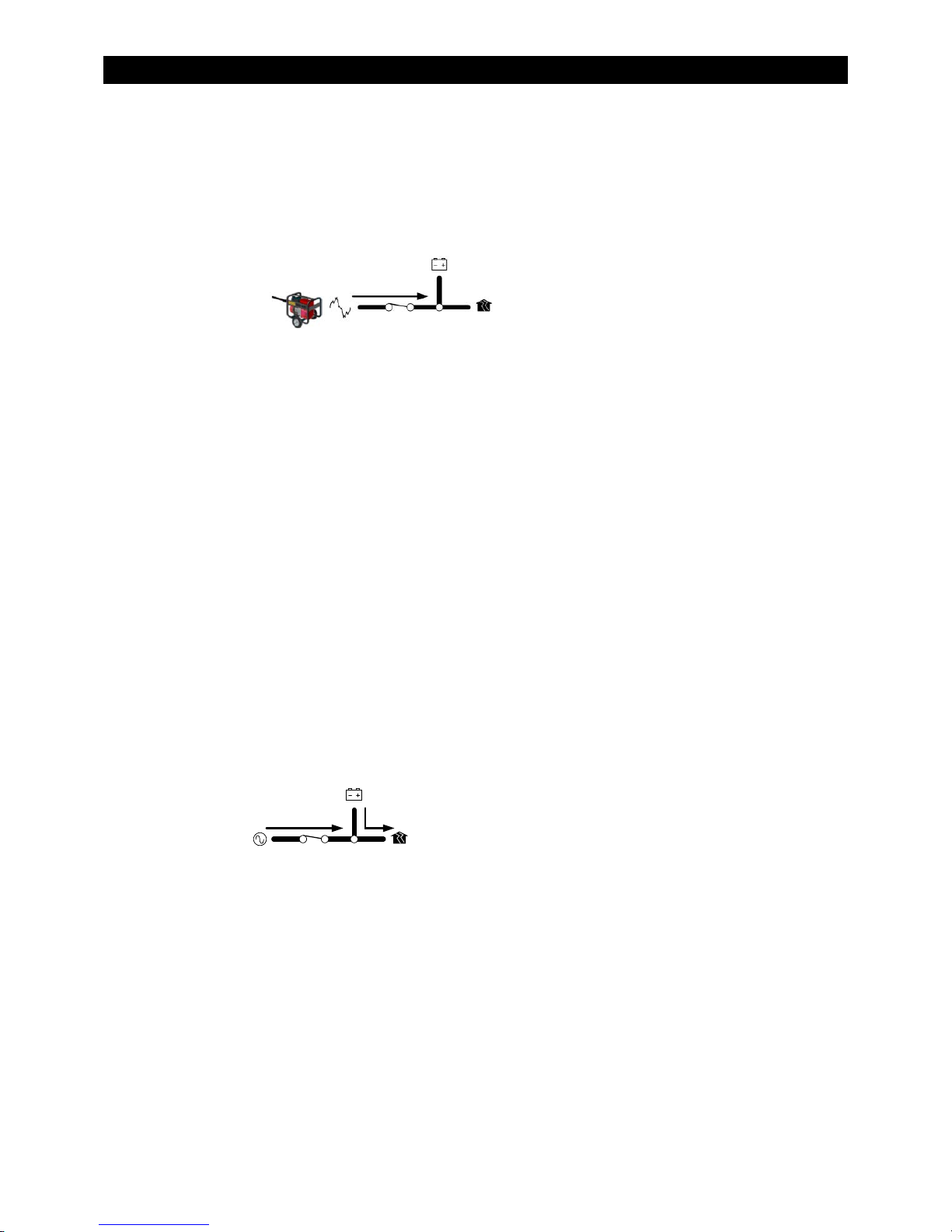
Each distinct mode, function, or operation is accompanied by a symbol representing the inverter and
that operation:
DC
RANSFER
AC IN AC OUT
These items represent the input from the AC
source, the output to the AC loads, DC functions
(inverting, charging, etc.), and the transfer relay.
Arrows on each symbol represent power flow.
The symbols may have other features depending on the operation.
AC Input Connection
The FXR inverter has one set of input connections. Only one AC source can be physically wired to it at
any time. However, two different AC sources can be used with an external transfer switch. It is
common for backup or grid-interactive systems to use the utility grid as the primary source, but switch
to a gas- or diesel-powered generator in emergencies. The inverter can be programmed with separate
input criteria for each source.
The inverter’s two input selections can be programmed for separate input modes (see below). The
selection (
beginning on page 76.)
NOTE:
of inverter requirements. Each selection can accept any AC source as long as it meets the
requirements of the FXR inverter and the selected input mode. If necessary, the
accept grid power. The opposite is also true.
The input types are labeled for grid and generator due to common conventions, not because
Grid
or
) can be chosen in the
Gen
AC Input and Current Limit
menu. (See the menu tables
selection can
Gen
Description of AC Input Modes
These modes control aspects of how the inverter interacts with AC input sources. Each mode is
intended to optimize the inverter for a particular application. The names of the modes are
Support, Grid Tied, UPS, Backup, Mini Grid
in Table 2. See page 25.
, and
GridZero
. The modes are summarized and compared
Generator
,
900-0167-01-00 Rev A 17
Operation
When multiple inverters are stacked together in parallel, the master inverter’s input mode is imposed
on all slaves. (See the stacking section on page 43.) The slave settings are not changed; they retain
any mode that was previously programmed. However, the slave will ignore its programmed mode
and use that of the master. This also applies to any parameters in the mode menu (
Connect Delay
, and so on).
The following pages compare the various functions of each input mode.
Generator
Voltage Limit
,
The
Generator
mode allows the use of a wide range of AC sources, including generators with a rough
or imperfect AC waveform. In other modes, a “noisy” or irregular waveform may not be accepted by
the inverter. (Self-excited induction generators may require this mode when used with the inverter.)
Generator
allows these waveforms to be accepted. The charging algorithm of this mode is designed
to work well with AC generators regardless of power quality or regulation mechanism. The generator
must still comply with the inverter’s nominal input specifications. (See page 29.)
:
Generator
Generator
Connect Delay
menus, depending on which input is being programmed.
mode does not mean that the inverter requires a generator input when using this
. It is available in both the
mode may allow the inverter to accept the power.
Grid AC Input Mode and Limits
input type; either selection can be used.
Gen
and the
BENEFITS:
The FXR inverter can charge the batteries from the generator even when the generator is undersized, of low
quality, or has other problems. See page 32 for recommended parameters for sizing a generator.
If the utility grid is unstable or unreliable,
A programmable delay time is available which will allow a generator to stabilize before connection. In the
MATE3, this menu item is
Gen AC Input Mode and Limits
NOTES
Any AC fluctuations that are accepted by the inverter will be transferred to the output. The loads will be
exposed to these fluctuations. It may not be advisable to install sensitive loads under these conditions.
The name of
mode. The use of this mode does not require the use of the
Conversely, the inverter is not required to be placed in this mode because a generator is installed.
Support
The
Support
amount of current available from the source is limited due to size, wiring, or other reasons. If large
loads are required, the FXR inverter augments (supports) the AC source. The inverter uses battery
power and additional sources to ensure that the loads receive the power they demand.
In the MATE3 system display, the
input. The
effect if the AC demand on either input exceeds the
BENEFITS
Large inverter loads can be powered while staying connected to the AC input, even if the input is limited.
The added battery power prevents overload of the input source, but the batteries are not in constant use.
The FXR inverter will offset the loads with excess renewable energy if it is available from the batteries. See
page 42 for more information.
18
mode is intended for systems that use the utility grid or a generator. In some cases the
Gen Input AC Limit
:
Grid Input AC Limit
dictates the maximum AC draw for the Grid
sets the maximum draw for the Gen input. The Support function takes
AC Limit
setting.
900-0167-01-00 Rev A

Operation
NOTES
:
IMPORTANT:
The inverter will draw energy from the batteries when the loads exceed the
appropriate
discharge to the Low Battery Cut-Out point. The inverter will shut down with a Low
Battery error. (See pages 27 and 62.) To prevent the loss of power, load use should be
planned accordingly.
IMPORTANT:
A “noisy” or irregular AC source may prevent
inverter will transfer the power, but will not support the source, charge the batteries, or
interact with the current in any other way. This problem is more common with
generators smaller than the wattage of the inverter.
AC Limit
A programmable delay time is available which will allow an AC source to stabilize before connection. In the
MATE3, this menu item is
Gen AC Input Mode and Limits
Connect Delay
menus, depending on which input is being programmed.
Because the inverter limits the current draw from the AC source, it will reduce the charge rate as necessary
to support the loads. If the loads equal the appropriate
If the AC loads
exceed
the
AC Limit
inverter will take power from the batteries and use it to support the incoming AC current.
. With sustained loads and no other DC source, the batteries may
Support
. It is available in both the
AC Limit
from working normally. The
Grid AC Input Mode and Limits
setting, the charge rate will be zero.
setting, the Support function is activated. Instead of charging, the
and the
The
Support
function is not available in any other input mode.
Grid Tied
IMPORTANT:
Selling power to the utility company requires the authorization of the local electric
jurisdiction. How the utility company accommodates this will depend on their policies
on the issue. Some may pay for power sold; others may issue credit. Some policies may
prohibit the use of this mode altogether. Please check with the utility company and
obtain their permission before using this mode.
The
Grid Tied
using power from the utility grid for charging and loads, the inverter can also convert excess battery
power and sell it to the utility grid. Excess battery power usually comes from renewable energy
sources, such as PV arrays, hydroelectric turbines, and wind turbines.
NOTE:
This mode is not available in 12-volt FXR models. It does not appear on the system display’s
list of available input modes.
The grid-interactive function uses Offset operation. See page 42 for more information.
mode allows the FXR inverter to become grid-interactive. This means that in addition to
BENEFITS
Excess power is returned to the utility grid.
:
The inverter will offset the loads with excess renewable energy if it is available from the batteries.
If the excess energy is greater than the AC demand (the load size), the excess will be sold to the grid.
900-0167-01-00 Rev A
19

Operation
NOTES
:
The inverter has a delay before selling will begin. This function, the
setting of five minutes. During this time, the inverter will not connect to the utility grid. The timer is adjustable
in the
Grid Interface Protection
Upon initial connection to the utility grid, the inverter may be required to perform a battery charging cycle.
This may delay the operation of the grid-interactive function.
The grid-interactive function only operates when excess DC (renewable) power is available.
The grid-interactive function is not available in any of the other input modes.
When power is returned to the utility grid, it may be possible to reverse the utility meter. However, this
depends on other loads in the system. Loads on the main panel (not on the inverter’s output) may consume
power as fast as it is sold. The meter would not run backwards, even if the system display showed the
inverter selling power. The result of selling would be to reduce AC power consumption, not reverse it.
The amount of power an inverter can sell is not necessarily equal to its specified output wattage. The
Maximum Sell Current
the
Grid Interface Protection
The amount of power that is sold is controlled by the utility grid voltage. The wattage sold equals this
voltage multiplied by the current. For example, if the inverter sells 15 amps and the voltage is 116 Vac,
the inverter will sell 1.74 kVA. If the voltage is 125 Vac, the inverter will sell 1.88 kVA. Additionally,
output will vary with inverter temperature, battery type, and other conditions.
This recommendation is specifically for the inverter’s grid-interactive function. In some cases, the
source may be sized larger to account for environmental conditions or the presence of DC loads. This
depends on individual site requirements.
can be decreased if it is necessary to limit the power sold. This item is available in
menu (see below).
menu (see below).
Re-Connect Delay Timer
, has a default
Grid Interface Protection Menu
Due to varying requirements in different locations around the world, the grid-interactive settings are
adjustable. These adjustments are made in the
This menu is only available to operators with installer-level access. There are firm rules concerning the
acceptable voltage range, frequency range, clearance time during power loss, and reconnect delay when
exporting power to the utility. Generally it is expected that the end user cannot alter the settings.
The installer password must be changed from the default in order to get access to these settings. Once this
password has been changed, the settings can only be accessed with the MATE3 installer password.
See the tables beginning on page 76 for the locations of all menu items in the MATE3 menus.
The grid-interactive function can only operate while the utility grid power is stable and within specific limits.
In Grid Tied mode, the inverter will operate in accordance with the Grid Interface Protection settings.
The default settings and ranges are listed in the tables which begin on page 76.
If the AC voltage or frequency vary outside the Grid Interface Protection limits, the inverter will
disconnect from the utility grid to prevent selling under unacceptable conditions. These limits override
the AC source acceptance limits described on page 30, which are used in other input modes. The
inverter will not reconnect until the source is acceptable for the duration of the Re-Connect Delay Timer.
If the inverter stops selling or disconnects due to Grid Interface Protection, the MATE3 will show the
reason. Sell Status messages are listed on page 66. Disconnect messages are listed on page 65. Often
these messages will be the same.
Before operating in Grid Tied mode, contact the utility company that provides power to the installation.
They can provide information regarding the rules that must be followed in order to export power back
to the utility. The items in the following list are the selectable Grid Interface Protection options. The
utility company may need to review these items to make certain their standards are met.
Grid Interface Protection
menu.
20 900-0167-01-00 Rev A

Operation
The utility may simply name a standard to be followed, as with UL1741 for the United States. It may be
necessary to look up the requirements for a local standard and program them accordingly.
STAGE 1 Voltage (basic settings)
Over Voltage Clearance Time (seconds)
Over Voltage Trip (AC Voltage)
Under Voltage Clearance Time (seconds)
Under Voltage Trip (AC Voltage)
STAGE 2 Voltage (if required by utility)
Over Voltage Clearance Time (seconds)
Over Voltage Trip (AC Voltage)
Under Voltage Clearance Time (seconds)
Under Voltage Trip (AC Voltage)
See the tables beginning on page 76 for the default settings and ranges.
Frequency Trip
Over Frequency Clearance Time (seconds)
Over Frequency Trip (Hertz)
Under Frequency Clearance Time (seconds)
Under Frequency Trip (Hertz)
NOTE: The Frequency Trip settings are dependent on
the inverter’s operating frequency, which must be set
correctly. See page 11.
Mains Loss
Clearance Time (seconds)
Reconnect Delay (seconds)
Frequency and Phase Coordination
Several other inverter adjustments are located in the
Grid Interface Protection
items can only be changed with installer-level access.
The FXR inverter’s operating frequency can be selected to either 50 or 60 Hz using the
Protection
See page 28 for more information on the inverter’s frequency.
The FXR inverter’s stacking function includes the option called
menu item is
source is required to deliver appropriate input to all inverters in a stacked system. If the master or subphase
master inverters do not sense an acceptable AC source, the entire system disconnects from the source.
None of the inverters will reconnect until the source is acceptable for the duration of the appropriate timer.
If the inverter is in Grid Tied mode, the Re-Connect Delay timer is used.
If the inverter is any other AC input mode, the Connect Delay timer is used.
See pages 29 and 32 for more information on input acceptance and the transfer function.
menu. This setting changes the inverter’s input acceptance parameters, as well as its output.
Multi-Phase Coordination
Coordinated AC Connect/Disconnect
. The default setting is No. If selected to
menu. These sensitive
Grid Interface
. The selectable
, the AC
Yes
See page 43 for more information on the stacking function and subphase master inverters.
See the tables beginning on page 76 for the default settings and ranges.
UPS
In
UPS
Failure
mode, the FXR parameters have been optimized to reduce the response time. If the utility grid
becomes unstable or is interrupted, the inverter can transfer to inverting with the fastest possible
response time. This allows the system to support sensitive AC loads with minimal interruption.
BENEFITS
Constant power is provided to the loads with virtually no drop in voltage or current.
NOTES
Due to the need for the FXR inverter to react quickly to AC source fluctuations, it must remain fully active at
all times. The inverter requires a continuous consumption of 42 watts.
For this reason, the Search function does not operate in this mode. (See page 28.)
900-0167-01-00 Rev A 21
:
:
Operation
Backup
Failure
The
Backup
This source will pass through the FXR inverter’s transfer circuit and will power the loads unless utility
power is lost. If utility grid power is lost, then the inverter will supply energy to the loads from the
battery bank. When the utility power returns, it will be used to power the loads again.
BENEFITS
This mode will continuously maintain the batteries in a fully-charged state. It does not have the overhead
consumption of the
Mini Grid
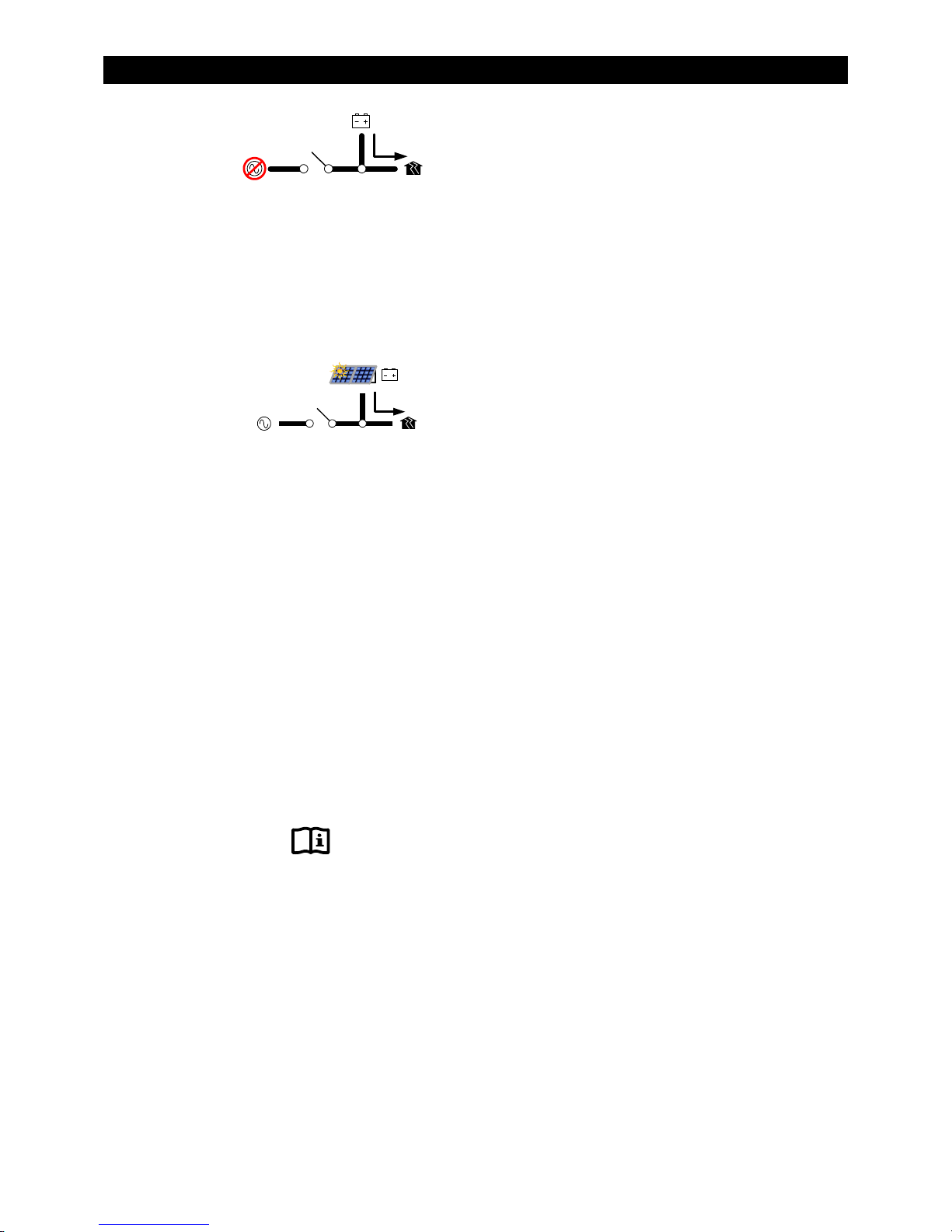
In
Mini Grid
(and renewable) energy. The inverter only connects to the AC source (usually the utility grid) when
the batteries run too low.
The FXR inverter runs on battery-supplied power for as long as the batteries can be sustained. It is
expected that the batteries will also be charged from renewable sources such as PV. When the
batteries become depleted, the system reconnects to the utility grid to operate the loads.
The inverter will reconnect to the utility grid if the battery voltage decreases to the
set point and remains there for the
begin on page 76.
mode is intended for systems that have utility grid available as the primary AC source.
:
mode.
UPS
mode, the FXR inverter automatically rejects an AC source and runs solely from battery
Connect to Grid
time period. These items are shown in the tables which
Delay
While connected to the utility grid, the FXR charger can be set either on or off. If the charger is turned
on, the inverter will proceed through a full charging cycle. Upon reaching float stage, the inverter will
disconnect from the grid.
If the inverter is connected to the utility grid and the charger is turned off, another DC source such as
renewable energy should be present to charge the batteries. The inverter will observe the batteries as
if it was performing the charge. When the batteries reach the required voltages and charging times to
achieve float stage, the inverter will disconnect from the grid. This means that the regulator for the
renewable source must be set to the same settings as the inverter (or higher). Check the settings of
both devices as needed.
See page 33 for more information on the battery charging cycle.
BENEFITS
Mini Grid
possible if certain conditions are met. See below.
NOTES
The FXR inverter will offset the loads with excess renewable energy if it is available from the batteries.
See page 42 for more information on Offset operation. However, the Offset function is inapplicable when
the inverter disconnects from an AC source. The renewable energy supports the inverting function instead.
Mini Grid
display. However, it is not compatible with
Grid
:
mode allows a system to minimize or eliminate dependence on the utility grid. This is only
:
mode has similar priorities to the high-battery transfer (
and cannot be used at the same time. When using
HBX
mode, the system display should disable
to prevent conflicts.
HBX
) function used by the MATE3 system
HBX
Mini
22 900-0167-01-00 Rev A
Operation
Mini Grid
system display. These functions do not have similar priorities to
inverter’s connection and disconnection with the grid.
When deciding whether to use
Mini Grid logic is based in the FXR inverter. After programming, it can function in the absence of the
Mini Grid can use utility grid power to fully recharge the batteries every time it reconnects to the grid.
HBX set points have a wide range of settings. Mini Grid uses settings intended to protect the batteries
HBX works more efficiently with a larger renewable source, but there is no specification for renewable
Mini Grid is one of seven inverter-level functions (modes) which share a single input. Selecting it
See Table 6 on page 54 for a comparison summary. Pages 53 and 54 have more information on HBX,
mode is also incompatible with the
Mini Grid
MATE3. HBX logic is based in the MATE3. It cannot function unless the MATE3 remains operating.
HBX can only do so under specific circumstances.
from excessive discharge; however, most of its settings are automatic and do not allow customization.
size. Mini Grid cannot work properly unless the renewable source is larger than the size of the loads. If
this condition is not met, Mini Grid will not disconnect the inverter from the utility grid.
prevents any other input mode from being used. HBX is a system-level function which can be
combined with the settings of other input modes.
Grid Use Time, Load Grid Transfer, and other functions of the system display.
Grid Use Time
mode or
HBX
and
Load Grid Transfer
Mini Grid
Mini Grid
, the user should consider the aspects of each.
should not be used with these functions.
or
functions of the MATE3
, but they do control the
HBX
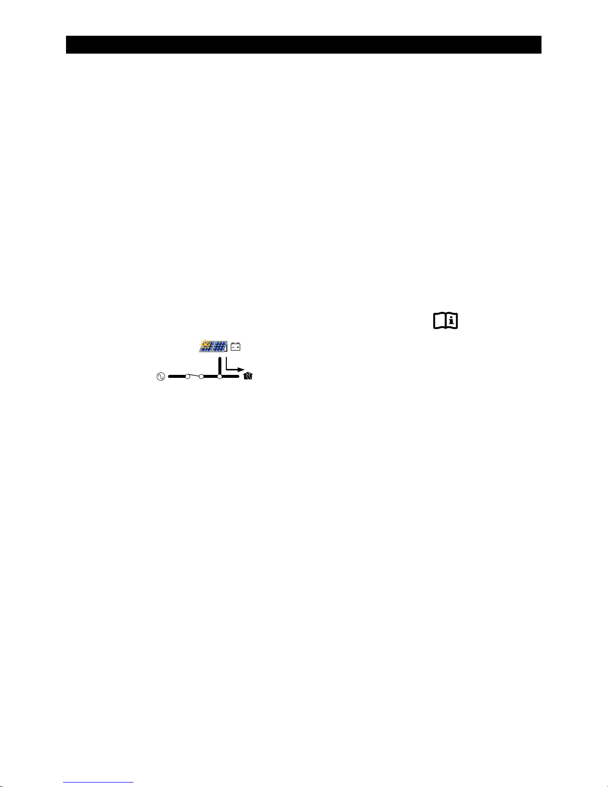
GridZero
In
GridZero
mode, the FXR inverter remains grid-connected, but prioritizes the use of battery or
renewable sources to run loads. It uses only renewable energy to recharge the batteries. The inverter
tries to “zero” the use of the utility grid, drawing on AC power only when needed to supplement
stored DC sources. Note that the inverter draws up to 1 Aac regardless of the DC sources.
In the MATE3 system display, the selectable options are
DoD Volts
battery power to the loads when the batteries exceed the
DoD Volts
and
DoD Amps
. The inverter sends
setting. (12-, 24-, and 48-volt
systems must exceed the setting by 0.2, 0.4, and 0.8 Vdc respectively.) As the battery voltage decreases
to
DoD Volts
, the inverter reduces the current toward zero. It will maintain the batteries at this setting.
The FXR inverter can manage large quantities of power. To prevent damage to the batteries from
rapid discharge, the rate of discharge can be limited using the
DoD Amps
setting. This item should be
set lower than the current provided by the renewable source.
When
DoD Volts
the loads. However, it will also leave less of a battery reserve in the event of a grid failure.
When
DoD Volts
reserve. However, not as much renewable energy will be sent to the loads.
is set low, this mode allows more renewable energy to be delivered from the batteries to
is set high, the batteries will not be discharged as deeply and will retain more of a backup
The renewable energy source needs to exceed the size of all loads and possible losses. The renewable
source must also charge the batteries. The inverter does not charge the batteries in
GridZero
mode.
BENEFITS
This mode seamlessly blends the use of battery power and grid power. It puts renewable energy to the
most effective use without selling power to the utility grid.
GridZero
The inverter remains connected to the utility grid in case the grid is needed. If large loads require the use of
grid power, no transfer is necessary to support the loads.
900-0167-01-00 Rev A 23
:
mode minimizes dependence on the grid as long as certain conditions are met.

Operation
NOTES
:
IMPORTANT:
Setting
DoD Volts
not have sufficient reserve to provide backup in the event of a grid failure. To prevent
the loss of power, load use and the
too low will severely discharge the batteries. The battery bank may
DoD Volts
setting should be planned accordingly.
If the renewable energy source is not greater than the size of the inverter loads, this mode will not work well
over time. The renewable source must be capable of charging the batteries as well as running the loads.
This occurs when renewable energy production exceeds the
DoD Amps
setting.
The inverter will offset the loads with excess renewable energy if it is available from the batteries. See
page 42 for more information on Offset operation. However, the behavior of Offset in
different because it uses the
DoD Volts
exclusively.
GridZero
mode is
The inverter’s battery charger cannot be used in this mode. However, the charger menu settings and timer
operations are not changed when this mode is selected.
The battery should be discharged whenever possible in the attempt to “zero” the grid usage. If the
setting is limited or loads are not present, the batteries will be unable to accept much renewable
Amps
recharging the next time it is available. The renewable energy will be wasted, leaving the system
dependent on the utility grid more than necessary.
DoD
24
900-0167-01-00 Rev A

Operation
Table 2 Summary of Input Modes
Mode Summary Benefits Cautions Intended Charger
Generator
Accepts power
from an
irregular or
low-quality
AC source
Can use AC that may be
unusable in other
modes
Can charge even with a
poor generator or
low-quality AC source
Will pass irregular or
low-quality power to
the output; could
damage sensitive loads
Offset unavailable
Source:
Generator
Loads:
Nonsensitive
devices
Performs three-stage
charge and goes
silent as specified by
settings
Support
Grid Tied
UPS
Backup
Adds battery
power to
augment an
AC source that
has limited
output
Inverter sells
excess power
(renewable)
to utility;
available in
24-volt and
48-volt
models only
In grid failure,
unit switches
to batteries
with fastest
possible
response time
In grid failure,
unit switches
batteries to
support loads
Can use battery power
in conjunction with
AC source
Offset operation sends
excess DC to loads
Bidirectional input
Can reduce utility bills
and still provide backup
Offset operation sends
excess DC to loads
Any additional Offset
excess is sold to the grid
Quick backup for
sensitive devices during
grid outage
Simple use compared to
other modes; often
used with generators for
this reason
Less idle power than
Does not drain battery
as in
Support
Drains batteries during
support; intended for
intermittent use only
May not function with
low-quality AC source
Requires utility
approval
Other approvals may be
required depending on
electrical codes
Has exact requirements
for accepting AC input
Requires renewable
energy source
Uses higher idle power
than other modes
Search function
unavailable
Offset unavailable
Has none of the special
functions described in
other modes
UPS
Source:
Grid or
Generator
Loads:
Can be
larger than
AC source
Source:
Grid
Loads:
Any type
Source:
Grid
Loads:
PC, audio,
video, etc.
Source:
Grid or
Generator
Loads:
Any type
Performs three-stage
charge and goes
silent as specified by
user settings
Performs three-stage
charge and goes
silent as specified by
user settings
Performs three-stage
charge and goes
silent as specified by
user settings
Performs three-stage
charge and goes
silent as specified by
user settings
MiniGrid
GridZero
Stays off grid
most of the
time; only uses
grid when
batteries low
On-grid but
actual grid use
is minimized
(“zeroed”) with
battery and
renewable
power; does
not sell or
Can minimize/eliminate
dependence on grid
Offset operation sends
excess DC to loads (but
only when on grid)
Can minimize
dependence on grid
Offset operation sends
excess DC to loads at
adjustable rate
Remains on-grid to
avoid transfer problems
charge
900-0167-01-00 Rev A 25
Will not work properly
unless renewable
source is above a
certain size
Conflicts with related
modes in MATE3
Discharges batteries
while remaining on grid
Will not work properly
unless renewable
source is above a
certain size
Battery charger
inoperative
Source:
Grid
Loads:
Any type
Source:
Grid
Loads:
Any type
Performs three-stage
charge on reconnect;
if charger is disabled,
inverter emulates
charge cycle from
external source and
reacts accordingly
Charger inoperative;
batteries must be
charged using an
external (renewable)
energy source

Operation
NOTES:
26 900-0167-01-00 Rev A

Operation
Description of Inverter Operations
The items in this section are operations common to all FXR inverters. These are used in most or all of
the input modes described in the preceding section.
Some of the items in this section are functions which can be manually selected, enabled, or
customized. Other items are general topics or applications for the inverter. These items may not have
their own menus, but their activity can still be influenced or optimized by changing certain settings.
Any of these items may need to be adjusted so that the inverter is best matched to a particular
application. The operator should review these items to see which are applicable.
All items described as settable or adjustable have set points which can be accessed using the
system display. The default settings and ranges of adjustment are listed in the menu tables which
begin on page 76 of this manual.
Inverting
This is the FXR inverter’s primary task. The inverter converts DC voltage from batteries into AC voltage
that is usable by AC appliances. It will continue to do this as long as the batteries have sufficient
energy. The batteries can be supplied or recharged from other sources, such as solar, wind, or
hydroelectric power.
The inverter’s design uses a transformer and a high-frequency H-Bridge FET module to achieve the
required high-wattage output. The inverter can deliver the rated wattage continuously at 25°C. The
maximum output is derated at temperatures exceeding 25°C. See pages 67 and 71 for these wattages.
Measure the total load wattage so that it does not exceed the inverter’s capacity. The inverter cannot
maintain its AC voltage under an excessive load. It will shut down with a
V
DC and AC Voltages
The FXR inverter requires batteries to operate
V
. Other sources may not maintain DC voltages that
Low Output Voltage
error.
are consistent enough for the inverter to operate reliably.
CAUTION: Equipment Damage
Do not substitute other DC sources in place of the batteries. High or irregular voltages
may damage the inverter. It is normal to use other DC sources with the batteries and
the inverter, but not in place of the batteries.
The following items will affect the inverter’s operation. These are only used when the inverter is
generating AC power on its own.
Low Battery Cut-Out
DC voltage drops below a specified level for 5 minutes, the inverter will stop functioning. The MATE3 will
give a
Low Battery V
on the MATE3 system display.
: This function prevents the inverter from draining the batteries completely. When the
error. This is one of the error messages described on page 62. It appears as an event
This function is intended to protect both the batteries and the inverter’s output. (Continuing to invert on a
low DC voltage may produce a distorted waveform.) This item is adjustable.
Low Battery Cut-In
point for 10 minutes, the error will clear and the inverter will resume functioning. This item is adjustable.
Connecting an AC source for the inverter to charge the batteries will also clear a low battery error.
900-0167-01-00 Rev A 27
: The recovery point from Low Battery Cut-Out. When the DC voltage rises above this
 Loading...