

Page 1
FXR Series Inverter/Charger
FXR2012E FXR2024E FXR2348E
VFXR2612E VFXR3024E VFXR3048E
Installation Manual
Page 2

About OutBack Power Technologies
OutBack Power Technologies is a leader in advanced energy conversion technology. OutBack products include
true sine wave inverter/chargers, maximum power point tracking charge controllers, and system communication
components, as well as circuit breakers, batteries, accessories, and assembled systems.
Applicability
These instructions apply to OutBack inverter/charger models FXR2012E, FXR2024E, FXR2348E, VFXR2612E,
VFXR3024E, and VFXR3048E only.
Contact Information
Address: Corporate Headquarters
17825 – 59
Suite B
Arlington, WA 98223 USA
Telephone:
Email: Support@outbackpower.com
Website: http://www.outbackpower.com
.360
+1
+1.360.618.4363 (Technical Support)
+1.360.435.6019 (Fax)
th
Avenue N.E.
.435.6030
European Office
Hansastrasse 8
D-91126
Schwabach, Germany
+49.9122.79889.0
+49.9122.79889.21 (Fax)
Disclaimer
UNLESS SPECIFICALLY AGREED TO IN WRITING, OUTBACK POWER TECHNOLOGIES:
(a) MAKES NO WARRANTY AS TO THE ACCURACY, SUFFICIENCY OR SUITABILITY OF ANY TECHNICAL OR OTHER
INFORMATION PROVIDED IN ITS MANUALS OR OTHER DOCUMENTATION.
(b) ASSUMES NO RESPONSIBILITY OR LIABILITY FOR LOSS OR DAMAGE, WHETHER DIRECT, INDIRECT,
CONSEQUENTIAL OR INCIDENTAL, WHICH MIGHT ARISE OUT OF THE USE OF SUCH INFORMATION. THE USE OF
ANY SUCH INFORMATION WILL BE ENTIRELY AT THE USER’S RISK.
OutBack Power Technologies cannot be responsible for system failure, damages, or injury resulting from
improper installation of their products.
Information included in this manual is subject to change without notice.
Notice of Copyright
FXR Series Inverter/Charger Installation Manual © 2015 by OutBack Power Technologies. All Rights Reserved.
Trademarks
OutBack Power, the OutBack Power logo, FLEXpower ONE, Grid/Hybrid, and OPTICS RE are trademarks owned
and used by OutBack Power Technologies, Inc. The ALPHA logo and the phrase “member of the Alpha Group”
are trademarks owned and used by Alpha Technologies Inc. These trademarks may be registered in the United
States and other countries.
Date and Revision
February 2015, Revision A
Part Number
900-0168-01-00 Rev A
Page 3

Table of Contents
Introduction ................................................................................................. 5
Audience ................................................................................................................................................................................. 5
Welcome to OutBack Power Technologies ................................................................................................................. 5
Models ...................................................................................................................................................................................... 6
Inverter Model Names .................................................................................................................................................................... 6
Components and Accessories ..................................................................................................................................................... 6
Planning ...................................................................................................... 9
Applications ........................................................................................................................................................................... 9
Input Modes ..................................................................................................................................................................................... 10
Renewable Energy ......................................................................................................................................................................... 10
Battery Bank ..................................................................................................................................................................................... 11
Generator .......................................................................................................................................................................................... 13
Installation ................................................................................................. 15
Location and Environmental Requirements ............................................................................................................ 15
Tools Required .................................................................................................................................................................... 15
Mounting .............................................................................................................................................................................. 16
Dimensions .......................................................................................................................................................................... 16
Terminals and Ports .......................................................................................................................................................... 17
Grounding ........................................................................................................................................................................................ 18
DC Wiring ............................................................................................................................................................................. 20
AC Wiring.............................................................................................................................................................................. 23
AC Sources ........................................................................................................................................................................................ 24
ON and OFF Wiring ........................................................................................................................................................... 25
Accessory Wiring ............................................................................................................................................................................ 25
AUX Wiring .......................................................................................................................................................................... 26
Generator Control .......................................................................................................................................................................... 27
AC Configurations ............................................................................................................................................................. 29
Single-Inverter ................................................................................................................................................................................. 29
Multiple-Inverter AC Installations (Stacking) ........................................................................................................................ 30
Stacking Configurations .............................................................................................................................................................. 31
Functional Test ................................................................................................................................................................... 36
Emissions .............................................................................................................................................................................. 36
Symbols Used ..................................................................................................................................................................... 36
Definitions ............................................................................................................................................................................ 37
Index ......................................................................................................... 39
900-0168-01-00 Rev A 3
Page 4

Table of Contents
List of Tables
Table 1 Models ................................................................................................................................................................. 6
Table 2 Components and Accessories .................................................................................................................... 6
Table 3 Battery Bank Elements .................................................................................................................................12
Table 4 Ground Conductor Size and Torque Requirements .........................................................................18
Table 5 DC Conductor Size and Torque Requirements ...................................................................................20
Table 6 Terms and Definitions .................................................................................................................................37
List of Figures
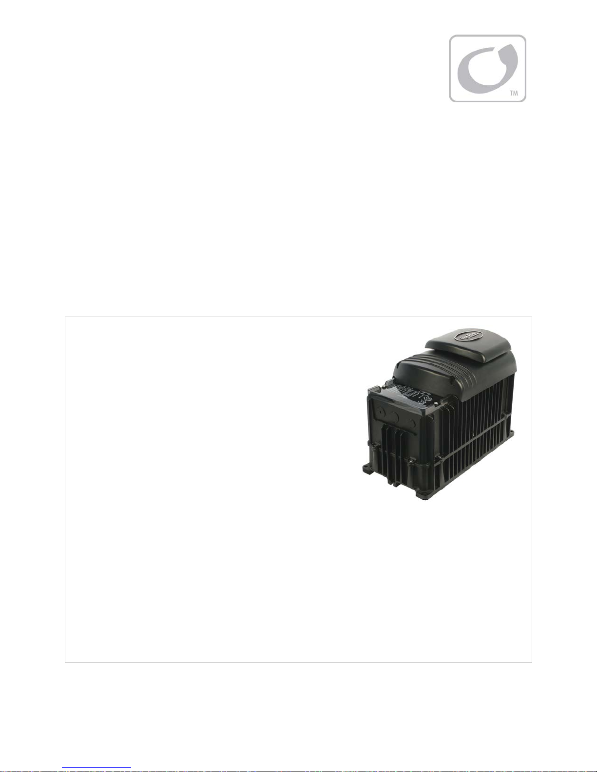
Figure 1 FXR Series Inverter/Charger ........................................................................................................................ 5
Figure 2 Components ..................................................................................................................................................... 7
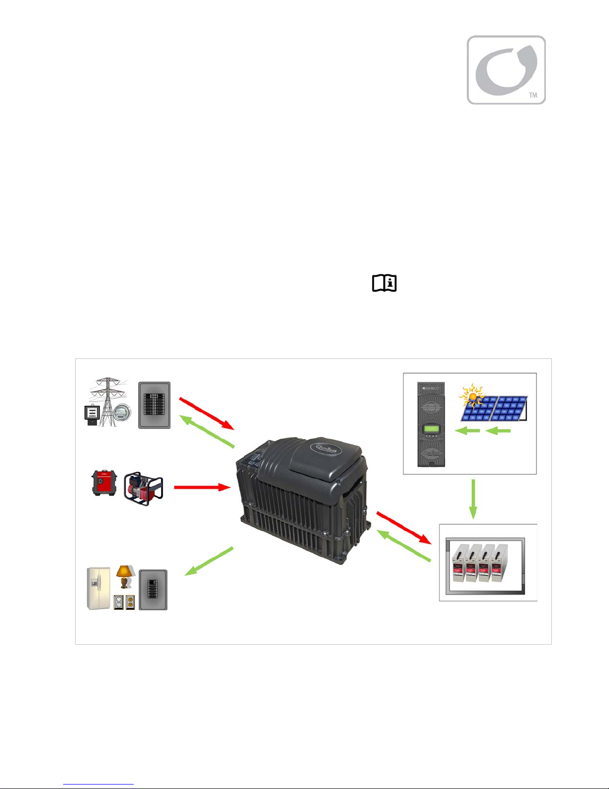
Figure 3 Applications (Example) ................................................................................................................................. 9
Figure 4 Dimensions ......................................................................................................................................................16
Figure 5 Terminals, Ports, and Features ..................................................................................................................17
Figure 6 DC Ground Lug ..............................................................................................................................................19
Figure 7 Chassis Ground/PE ........................................................................................................................................19
Figure 8 Required Order of Battery Cable Hardware .........................................................................................21
Figure 9 Battery Terminal Covers ..............................................................................................................................21
Figure 10 DC Cover Attachment ..................................................................................................................................22
Figure 11 Turbo Fan Wiring ...........................................................................................................................................22
Figure 12 AC Terminals ...................................................................................................................................................23
Figure 13 AC Sources .......................................................................................................................................................24
Figure 14 AC Sources and Transfer Relay .................................................................................................................24
Figure 15 ON/OFF Jumper and Connections ..........................................................................................................25
Figure 16 Accessory Connections ...............................................................................................................................25
Figure 17 AUX Connections for Vent Fan (Example) ............................................................................................26
Figure 18 AUX Connections for Diversion (Example) ...........................................................................................26
Figure 19 Two-Wire Generator Start (Example) .....................................................................................................27
Figure 20 Three-Wire Generator Start (Example) ..................................................................................................28
Figure 21 Single-Inverter Wiring
Figure 22 OutBack HUB10.3 and MATE3
Figure 23 Example of Parallel Stacking Arrangement (Three Inverters) .......................................................31
Figure 24 Parallel Wiring (Four Inverters) .................................................................................................................32
Figure 25 Example of Three-Phase Stacking Arrangement (Three Inverters) .............................................33
Figure 26 Example of Three-Phase Stacking Arrangement (Nine Inverters) ...............................................33
Figure 27 Three-Phase Wiring (Three Inverters) ....................................................................................................35
..................................................................................................................................29
..................................................................................................................30
4 900-0168-01-00 Rev A
Page 5
Introduction
Audience
This book provides instructions for the physical installation and wiring of this product.
e instructions are for use by qualified personnel who meet all local and governmental code
Thes
requirements for licensing and training for the installation of electrical power systems with AC and DC
voltage up to 600 volts. This product is only serviceable by qualified personnel.
Welcome to OutBack Power Technologies
Thank you for purchasing the OutBack FXR Series Inverter/Charger. This product offers a complete
power conversion system between batteries and AC power. It can provide backup power, sell power
back to the utility grid, or provide complete stand-alone off-grid service.
12
-, 24-, and 48-volt models
Output power from 2.0 kVA to 3.0 kVA
Designed to be integrated as part of an OutBack Grid/Hybrid™
system using FLEXware™ components
Battery-to-AC inverting which delivers single-phase adjustable
output for such standards as 230 Vac, 220 Vac, or 240 Vac
(at 50 or 60 Hz)
AC-to-battery charging (OutBack systems are battery-based)
Uses battery energy stored from renewable resources
~ Can utilize stored energy from PV arrays, wind turbines, etc.
~ OutBack FLEXmax charge controllers will optimize PV output
Inverter load support for a small AC source
Sell-back to utility (grid-interactive function)
~ Available in 24- and 48-volt models
Rapid transfer between AC source and inverter output with minimal delay time
Uses the MATE3™ System Display and Controller or the AXS Port™ SunSpec Modbus Interface (sold
separately) for user interface as part of a Grid/Hybrid system
Supports the OPTICS RE™ online tool1 for a cloud-based remote monitoring and control application
∼ Requires the MATE3 or the AXS Port
∼ Visit www.outbackpower.com to download
Uses the HUB10.3™ Communications Manager for stacking as part of a Grid/Hybrid system
~ Stackable in parallel and three-phase configurations
Figure 1 FXR Series Inverter/Charger
: This product has a settable AC output range. In this manual, many references to the output
NOTE
refer to the entire range. However, some references are made to 230 Vac or 50 Hz output. These are
intended as examples only.
1
Outback Power Technologies Intuitive Control System for Renewable Energy
900-0168-01-00 Rev A 5
Page 6
Introduction
Models
Vented FXR (VFXR) models are intended for indoor or protected installation only. Vented inverters
have an internal fan and use outside air for cooling. On average, the power of the vented models is
rated higher than sealed models due to their greater cooling capabilities.
Sealed FXR models are designed for harsher environments and can survive casual exposure to the
elements. However, enclosed protection is still recommended. (See page 15.) Sealed inverters
have an internal fan, but do not use outside air for cooling. To compensate, sealed models are also
equipped with the OutBack Turbo Fan assembly, using external air to remove heat from the chassis.
(Vented models are not equipped with the Turbo Fan and cannot use it.)
Table 1 Models
Model Type Power Battery Application
FXR2012E Sealed 2.0 kVA 12 Vdc Off-grid, backup
VFXR2612E Vented 2.6 kVA 12 Vdc Off-grid, backup
FXR2024E Sealed 2.0 kVA 24 Vdc Off-grid, backup, grid-interactive
VFXR3024E Vented 3.0 kVA 24 Vdc Off-grid, backup, grid-interactive
FXR2348E Sealed 2.3 kVA 48 Vdc Off-grid, backup, grid-interactive
VFXR3048E Vented 3.0 kVA 48 Vdc Off-grid, backup, grid-interactive
Inverter Model Names
FXR series model numbers use the following naming conventions.
The model number includes “FXR” as the inverter series. “R” indicates that the FXR was designed for
renewable applications. Off-grid and grid-interactive functions are integrated in the same inverter.
Vented models are preceded with “V”, as in “VFXR3048E”. If a model number does not begin with “V”, it is a
sealed model and is equipped with a Turbo Fan. This is not indicated otherwise.
The first two digits show the wattage of that model. For example, “FXR2012E” is 2000 watts.
The second pair of digits shows the inverter’s nominal DC voltage. For example, “FXR2024E” is 24 volts.
The model number is followed by “E”. This designates the inverter’s output as nominally 230 Vac (used in
Europe, Africa, and other regions).
Components and Accessories
Table 2 Components and Accessories
Components to be Installed Accessories Included
Battery Terminal Cover, red FXR Inverter/Charger Installation Manual (this book)
Battery Terminal Cover, black FXR Inverter/Charger Operator’s Manual
AC Plate “WARNING ELECTRICAL SHOCK” sticker
DC Cover (DCC) or Turbo Fan Silicone Grease Packet
Remote Temperature Sensor (RTS)
6 900-0168-01-00 Rev A
Page 7

Introduction
AC Plate
This plate is used for installations which do not utilize OutBack’s
optional FLEXware conduit boxes. The knockouts are used to
install strain relief for flexible cable.
NOTE: This plate is not to be connected to conduit.
DCC (DC Cover)
This covers the DC terminal area on vented inverters. The DCC
provides space to mount other components such as a DC
current shunt.
Battery Terminal Cover
These protect the terminals from accidental contact. They are
made of stiff plastic with a snap-on design.
Always keep covers installed during normal operation.
Turbo Fan Cover
Included in place of the DCC on sealed inverters. Convectively cools
chassis with the external OutBack Turbo Fan to allow maximum power.
NOTE: Do not install the Turbo Fan on a vented inverter.
NOTE: The DC Cover or Turbo Fan does not replace the battery terminal
covers. These covers must be installed in addition to the DCC or fan.
900-0168-01-00 Rev A 7
Figure 2 Components
Page 8

Introduction
NOTES:
8 900-0168-01-00 Rev A
Page 9
Planning
k
Applications
OutBack inverter/chargers are designed to use a battery bank to store energy. They work together
with power from the utility grid or from renewable energy sources, such as photovoltaic (PV) modules,
wind turbines, and other renewable sources. These sources charge the battery, which in turn is used
by the inverter.
FXR series inverters have been designed to work with all types of renewable systems. These include
off-grid, backup, and interactive applications. The inverter’s settings can be changed to accommodate
many applications. Changes are made with the system display.
The FXR inverter has one set of terminals for a single AC source. However, it can use two different AC
sources when an external transfer switch is installed. The inverter can be independently programmed
for each source. It is common to use utility grid power and a gas or diesel generator. Other
combinations of AC sources are possible.
Utility Grid
AC Generator
OR
AC IN
AC OUT
Charge
Controller
PV Array
DC IN
AC IN
Loads
AC OUT
Battery Charging
AC or PV
DC OUT
Load Support
PV Harvest
Battery Ban
Figure 3 Applications (Example)
In Figure 3, the inverter uses a bidirectional AC input to sell power back to the utility grid. The power
being delivered to the grid (labeled “AC Out”) is excess AC power not being used by the AC loads.
Selling requires an inverter/charger with
900-0168-01-00 Rev A 9
Grid Tied
mode available and active.
Page 10

Planning
Input Modes
The FXR inverter has many modes of operation. See the FXR Series Inverter/Charger Operator’s Manual
for additional information on these modes, including reasons and considerations for using each mode.
The modes determine how the inverter interacts with an AC source. Each mode has functions and
priorities that are intended for a designated application. Each of the inverter’s input selections can be
set to a different operating mode to support different applications.
Generator: This mode is intended for a wide range of AC sources, including generators with a rough or
imperfect AC waveform. The inverter can use generator power even when the generator is undersized
or substandard.
Support: This mode is intended for systems using the utility grid or a generator. AC source size, wiring, or
other limitations may require temporary assistance to run very large loads. The inverter adds renewable or
battery power to the AC source to ensure that the loads receive the power they require. This mode can
reduce peak load demand from the utility.
Grid Tied: This mode is intended for grid-interactive systems. When renewable energy sources charge the
batteries above a selected “target” voltage, the inverter will send the excess energy to any loads. If the loads
do not use all the excess energy, then the inverter will send (sell) that energy to the utility grid.
This mode is only available in 24-volt and 48-volt models.
NOTE:
Backup: This mode is intended for systems that have the utility grid or a generator available, but do not
: This mode is intended for systems primarily intended to maintain power to the loads with minimal
UPS
interruption when switching between AC input and batteries. The response speed has been increased so
that if an AC disconnect occurs the response time will be minimized.
have specialty requirements such as selling or support. The AC source will flow through the inverter to
power the loads unless power is lost. If power is lost, then the inverter will supply energy to the loads from
the battery bank until the AC source returns.
Mini Grid: This mode is intended for systems that have the utility grid as an input and a sizable amount of
renewable energy. The system will run off the renewable energy until the battery voltage falls to a specified
low level. When this occurs, the inverter will connect to the utility grid to power the loads. The inverter will
disconnect from the utility grid when the batteries are sufficiently recharged.
Grid Zero
renewable energy. The loads will remain connected to the utility grid, but will restrict the grid use except
when no other power is available. The default power sources are the batteries and renewable energy, which
attempt to “zero” the use of the AC source. The batteries are discharged and recharged (from renewable
sources) while remaining grid-connected. This mode does not allow the inverter to charge batteries or sell.
: This mode is intended for systems that have the utility grid as an input and a sizable amount of
Programming
Selection of the input modes and all other inverter programming are performed using a system
display such as the MATE3. The system display can customize a wide range of parameters.
Renewable Energy
The inverter cannot connect directly to PV, wind turbines, or other renewable sources. The batteries
are the inverter’s primary source of power. However, if the renewable sources are used to charge the
batteries, the inverter can use their energy by drawing it from the batteries.
The renewable source is always treated as a battery charger, even if all of its power is used
immediately. The renewable source must have a charge controller, or some other regulation method,
to prevent overcharging. OutBack Power’s FLEXmax family of charge controllers can be used for this
purpose, as can other products.
10 900-0168-01-00 Rev A
Page 11
T
Planning
Battery Bank
When planning a battery bank, consider the following:
Cables:
will determine the placement of the battery bank. Other local codes or regulations may apply and may take
priority over OutBack recommendations.
Battery Type: The FXR inverter/charger uses a three-stage charge cycle.
~ The cycle was designed for lead-chemistry batteries intended for deep discharge. These include
~ Using OutBack’s Advanced Battery Charging (ABC), most charging stages can be reconfigured or
Nominal Voltage:
different depending on inverter model. Before constructing a battery bank, check the inverter model and
confirm nominal battery voltage.
Charger Settings and Maintenance:
usually recommended for safety reasons. It may be necessary to use a fan to ventilate the battery enclosure.
Batteries must be regularly maintained according to the instructions of the battery manufacturer.
Recommendations for battery cable size and length are shown on page 20. The maximum length
batteries for marine, golf-cart, and forklift applications. They also include gel-cell batteries and
absorbed glass-mat (AGM) batteries. OutBack Power recommends the use of batteries designed
specifically for renewable energy applications. Automotive batteries are strongly discouraged and will
have a short life if used in inverter applications.
omitted from the cycle if necessary. The charger can be customized to charge a wide range of battery
technologies including nickel, lithium-ion, and sodium-sulfur batteries. This programming is performed
using the system display.
These inverters are designed to work with specific battery bank voltages, which are
A vented battery enclosure may be required by electric code and is
IMPORTANT:
Battery charger settings need to be correct for a given battery type. Always follow
battery manufacturer recommendations. Making incorrect settings, or leaving them at
factory default settings, may cause the batteries to be undercharged or overcharged.
CAUTION: Hazard to Equipment
Batteries can emit vapors which are corrosive over long periods of time. Installing
the inverter in the battery compartment may cause corrosion which is not covered
by the product warranty. (Sealed batteries may be an exception.)
Bank Size:
Battery bank capacity is measured in amp-hours. Determine the required bank specifications as
accurately as possible, beginning with the items below. This avoids underperformance or wasted capacity.
These ten items are obtainable in different places, summarized in Table 3 on the next page. Some of the
information is specific to the site or application. Some can be obtained from the battery manufacturer.
Information on OutBack products is available from OutBack Power Technologies or its dealers.
A. Size of load:
B. Daily hours of use:
C. Days of autonomy:
hese are the most basic
and essential factors used
to determine bank size.
D. Application: This often helps define or prioritize the previous three items. Off-grid systems often
require enough capacity to last for an extended period before recharging. Grid-connected systems
frequently need only enough capacity for short-term backup during outages.
E. Conductor efficiency: Wire size and other factors
Any losses are essentially amp-hour
will waste power due to resistance and voltage drop.
Typical acceptable efficiency is 96 to 99%.
F. Inverter efficiency: FXR specifications list “Typical
Efficiency” to help estimate operating loss.
capacity that the system cannot use.
The battery bank size can be
increased to account for losses.
900-0168-01-00 Rev A
11
Page 12

Planning
G. System DC voltage: Each inverter model
requires a specific DC voltage to operate.
H. Battery voltage: Most individual battery
voltages are less than the system DC voltage.
The batteries may need to be placed in series to
deliver the correct voltage.
I. Capacity: Battery capacity, which is measured
in amp-hours, is not usually a fixed number.
It is specified based on the rate of discharge.
For example, the OutBack EnergyCell 200RE is
rated at 154.7 Ahr when discharged at the
Table 3 Battery Bank Elements
Item Source of information
A. Load Size Site-specific
B. Daily Hours Site-specific
C. Days of Autonomy Site-specific
D. Application Site-specific
E. Conductor Efficiency Site-specific
F. Inverter Efficiency Inverter manufacturer
G. System Vdc Inverter manufacturer
H. Battery Vdc Battery manufacturer
I. Capacity Battery manufacturer
J. Maximum DoD Battery manufacturer
5-hour rate (to terminal voltage 1.85 Vpc). This is a high rate of discharge that would hypothetically
drain the battery in 5 hours. The same battery is rated at 215.8 Ahr when used at the 100-hour rate.
Use the appropriate discharge rate (correlated to the expected loads) to measure the capacity of a
battery. Use battery specifications for terminal voltage 1.85 Vpc whenever possible.
NOTE: Capacity ratings are for batteries at 25°C. Capacity is reduced at cooler temperatures.
J. Maximum depth of discharge (DoD): Most batteries cannot be discharged below a certain level
without damage. The bank requires enough total capacity to keep this from happening.
To Calculate Minimum Battery Bank Size (refer to Table 3 for letter designations):
The load size, item A, is measured in watts. Compensate this figure for efficiency loss. Multiply the
1.
conductor efficiency by the inverter efficiency (E x F). (These items are represented as percentages,
but may be displayed as decimals for calculation.) Divide item A by the result.
2. Convert the compensated load into amperes (Adc). Divide the step 1 result by the system voltage
(item G).
3. Determine the daily load consumption in ampere-hours (amp-hours, or Ahr). Multiply the step 2
result by the daily usage hours (item B).
4. Adjust the total for required days of autonomy (the days the system must operate without
recharging) and the maximum DoD. Multiply the step 3 result by C and divide by J.
The result is the total amp-hour capacity required for the battery bank.
5. Determine the number of parallel battery strings required. Divide the Ahr figure from step 4 by the
individual battery capacity (I). Round the result to the next highest whole number.
6. Determine the total number of batteries required. Divide the system voltage by the battery voltage
(G ÷ H). Multiply the result by the step 5 result.
The result is the total required quantity of the chosen battery model.
EXAMPLE #1
A. Backup loads: 1.0 kW (1000 W)
B. Hours of use: 8
C. Days of autonomy: 1
D. Grid-interactive system (FXR2348E inverter)
E. Conductor efficiency: 98% (0.98)
F. Inverter efficiency: 93% (0.93)
G. System voltage: 48 Vdc
H. Batteries: OutBack EnergyCell 220GH (12 Vdc)
I. Capacity at 8-hour rate: 199.8 Ahr
J. Maximum DoD: 80% (0.8)
12 900-0168-01-00 Rev A
1) A ÷ [E x F] 1000 ÷ (0.98 x 0.93) = 1097.2 W
2) 1 ÷ G 1097.2 ÷ 48 = 22.9 Adc
3) 2 x B 22.9 x 8 = 182.9 Ahr
4) [3 x C] ÷ J [182.9 x 1] ÷ 0.8 = 228.6 Ahr
5) 4 ÷ I 228.6 ÷ 199.8 = 1.14 (rounded to 2)
6) [G ÷ H] x 5 [48 ÷ 12] x 2 strings = 8 batteries
Page 13

EXAMPLE #2
Planning
A. Backup loads: 720 W)
B. Hours of use: 3
C. Days of autonomy: 2
D. Off-grid system (VFXR3024E inverter)
E. Conductor efficiency: 97% (0.97)
F. Inverter efficiency: 92% (0.9)
G. System voltage: 24 Vdc
H. Batteries: OutBack EnergyCell 200RE (12 Vdc)
I. Capacity at 8-hour rate: 167.5 Ahr
J. Maximum DoD: 50% (0.5)
Generator
FXR inverters can accept power from a single-phase generator that delivers clean AC power in the range of
voltage and frequency specified for that model.
~ Inverters stacked for three-phase output can work with three-phase generators.
The inverter/charger can provide a start signal to control an automatic start generator. If automatic generator
starting is required, the generator must be an electric-start model with automatic choke. It should have
two-wire start capability. For other configurations, additional equipment may be required.
In any configuration, the inverter may need to be specifically programmed using the system display.
Perform all programming according to the specifications of the generator and the required operation of the
inverter. Parameters to be program med may include generator size, automatic starting requirements, and
potential fluctuations in generator AC voltage.
1) A ÷ [E x F] 720 ÷ (0.97 x 0.9) = 801.8 W
2) 1 ÷ G 824.7 ÷ 24 = 34.4 Adc
3) 2 x B 34.4 x 3 = 103.1 Ahr
4) [3 x C] ÷ J [103.1 x 2] ÷ 0.5 = 412.4 Ahr
5) 4 ÷ I 412.4 ÷ 167.5 = 2.5 (rounded to 3)
6) [G ÷ H] x 5 [24 ÷ 12] x 3 strings = 6 batteries
A generator that is to be installed in a building usually should
ground connections. The generator should only be bonded if there is a specific need. Local or national
codes may require the neutral and ground to be bonded at the main electrical panel. See page 19 for more
information on neutral-ground bonding.
have a bond between the neutral and
not
Generator Sizing
A generator should be sized to provide enough power for all the loads and the battery charger. The
generator size should assume maximum loads and maximum charging at the same time.
Available generator power may be limited by ratings for circuit breakers and/or generator connectors.
The generator must be able to provide current to all inverters on a given phase or leg. Minimum generator
2
is recommended to be twice the power of the inverter system. For example, a 2 kVA inverter should
size
have a 4 kVA generator. Many generators may not be able to maintain AC voltage or frequency for long
periods of time if they are loaded more than 80% of rated capacity.
2 This is the generator size after derating for environment, use, and other factors.
900-0168-01-00 Rev A 13
Page 14

Planning
NOTES:
14 900-0168-01-00 Rev A
Page 15

Installation
Location and Environmental Requirements
Sealed (FXR) models are resistant to water and other elements but are not designed for permanent
outdoor installations. If outdoor installation is required, the FXR inverter must be installed under
cover and protected from direct exposure to the environment. Vented (VFXR) models are not resistant
to water and other elements. They must be installed indoors.
The inverter can often be mounted in any position or orientation. If there is any exposure to moisture or
condensation, the inverter must not be mounted upside-down. This ensures that water will not accumulate
under the DC cover. However, it can still be mounted in other positions or orientations.
For installations where the inverter may be exposed to water spray, a sealed model must be used and
mounted either with the base down (shelf mounting) or with the AC wiring compartment facing down
(wall mounting). If mounted with the base down, water cannot be allowed to accumulate around the
inverter’s base. There is a drainage system on the base of the inverter to dispel condensation. If submerged,
water can enter this drain and cause failure.
Vented inverters must be installed in a weather-proof enclosure or enclosed area. These models are not
designed for exposure to water or excessive wind-blown dust and debris.
When inverters are installed with an OutBack FLEXpower system, the system must be installed in the upright
orientation due to the requirements of the circuit breakers.
Any inverter will perform more efficiently in locations offering plenty of air circulation. The recommended
minimum clearance is 5 cm (2 inches) on all sides of the inverter.
Any inverter will function to all of its specifications if operated in a range of –20°C to 50°C (–4°F to 122°F).
The inverter will function, but will not necessarily meet its specifications, if operated in a temperature range
of –40°C to 60°C (–40°F to 140°F). This is also the allowable temperature range for storage.
The FXR series of inverters carry an Ingress Protection (IP) rating of 20 and a Relative Humidity (RH) rating of
93% (non-condensing).
Inverter specifications are listed in the FXR Series Inverter/Charger Operator’s Manual.
Tools Required
Wire cutters/strippers
Torque wrenches
Assorted insulated screwdrivers
DVM or standard voltmeter
900-0168-01-00 Rev A 15
Page 16

Installation
Mounting
One person can install the FXR inverter, but installation may be easier with two people.
The unit has four mounting holes, one in each corner. Use fasteners in all corners for a secure installation.
IMPORTANT:
Use correct fasteners to secure the inverter to the mounting surface,
regardless of the type of surface. OutBack cannot be responsible for
damage to the product if it is attached with inadequate fasteners.
Due to the variance in other mounting methods, OutBack only endorses the use of FLEXware mounting
products or previous versions of OutBack mounting plates. Use M6 x 20 mm machine screws, one per
corner, to attach the inverter to the mounting plate. Follow the instructions with each mounting system.
Mount and secure each component before attaching any wiring.
When the inverter is used with other metal chassis, make sure that all chassis are grounded appropriately.
(See the grounding instructions on page 17.) Grounding other chassis may involve metal-to-metal contact,
or separate ground wires.
If using an OutBack FLEXware Mounting Plate, avoid large air gaps behind the plate. These can result
in louder mechanical noise during heavy inverting or charging. Mount the plate on a flat, solid
mounting surface.
Dimensions
Length 41 cm (16.25”)
Height
without
Turbo
30.5 cm (12”)
Width
21 cm (8.25”)
Height
with Turbo
33 cm (13”)
16
Figure 4 Dimensions
900-0168-01-00 Rev A
Page 17

p
Installation
Terminals and Ports
DC TERMINALS
These terminals connect to the
battery cables and the DC system.
See page 20 for instructions.
CONTROL WIRING TERMINAL BLOCK
These terminals receive control wires for a
variety of functions including generator control.
See pages 26 and 27 for instructions and the
Operator’s Manual for more information.
The Terminal Block can be unplugged from the
AC board for convenience. While installed, keep
screws tight and the block itself secured tightly
to the AC board to
These terminals receive wires for a manual
The jumper alongside these terminals overrides
them and turns the inverter on. (See page 25 for
instructions.) With the jumper installed, a switch
display can turn it off or on. The system display
These terminals deliver 12 Vdc up to 0.7 amps
(8.4 watts). The output can be switched on and
off for many functions. The default function is
programmed using the system display.
on/off switch to control the inverter.
cannot turn the inverter off, but the system
cannot turn it on if the jumper is not installed.
AUX OUTPUT (AUX+/AUX-)
to drive a cooling fan or the Turbo Fan.
The functions for the AUX output can be
revent malfunction.
INVERTER ON/OFF
ON/OFF JUMPER
See page 26 for details.
DC and AC
GROUND TERMINALS
These terminals connect to
a grounding system for
both batteries and AC. See
page 17 for instructions.
AC TERMINAL BLOCK
These terminals receive AC
input and output wires. See
page 23 for instructions.
XCT+/XCT-
Non-operational terminals.
Do not connect anything
to them.
MATE/HUB and RTS PORTS
These ports receive the RJ45
and RJ11 plugs from the
system display and Remote
Temp Sensor. See page 25
for instructions.
The ports are mounted
sideways. When viewed from
the left side, they appear as
shown below.
AUX LED INDICATOR
Orange LED indicator turns on when
12 Vdc output is present.
Figure 5 Terminals, Ports, and Features
: The INVERTER ON/OFF Jumper is installed to the ON position during manufacture, but the FXR
NOTE
inverter is given an external OFF command at the same time. Its initial state is OFF.
900-0168-01-00 Rev A
LED INDICATORS
These indicators display the inverter status and battery voltage.
The three BATTERY LED indicators (green, yellow, and red) are based on
DC voltage, and provide a very general idea of battery state.
The green INVERTER LED indicator shows if the inverting function is on.
The yellow AC IN LED indicator shows if an AC source is present.
The red ERROR LED indicator shows either a Warning or an Error. A
Warning is an alert for a problem that is not severe enough for
shutdown. An Error usually accompanies inverter shutdown.
17
Page 18

Installation
Wiring
It will be necessary to remove knockouts from the AC Plate to run wires. The AC Plate has one
knockout of ½” size and two knockouts of ¾” size. Install appropriate bushings to protect the wires.
Use copper wire only. Wire must be rated at 75°C or higher.
Grounding
WARNING: Shock Hazard
This unit meets the IEC requirements of Protection Class I.
The unit must be connected to a permanent wiring system that is grounded
according to the IEC 60364 TN standard.
The input and output circuits are isolated from ground. The installer is responsible for
system grounding according to all applicable codes.
For safety, the neutral and ground conductors should be mechanically bonded.
OutBack does not bond these conductors within the inverter. Some codes require
the bond to be made at the main panel only. Make sure that no more than one bond
is present in the AC system at any time.
WARNING: Shock Hazard
For all installations, the negative battery conductor should be bonded to the grounding
system at only one point. If the OutBack GFDI is present, it can provide the bond.
IMPORTANT:
Not all OutBack products can be used in a positive-ground system. If it is necessary to
build a positive-ground system with OutBack products, contact OutBack Technical
Support at +1.360.618.4363 before proceeding. Additionally, consult the online forum
at www.outbackpower.com/forum/, where this subject has been discussed extensively.
Table 4 Ground Conductor Size and Torque Requirements
Terminal Location Minimum Conductor Size Torque Requirements
Central AC Terminals
DC Box Lug
6 mm or #10 AWG (0.009 in) 2.8 Nm (25 in-lb)
16 mm or #6 AWG (0.025 in) 5.1 Nm (45 in-lb)
Table 4 contains OutBack’s recommendations for minimum safe cable sizes. Other codes may
supersede OutBack’s recommendations. Consult applicable codes for final size requirements.
18
900-0168-01-00 Rev A
Page 19

Installation
The inverter’s DC ground is a box lug located next to the negative DC battery terminal. This lug
accepts up to 70 mm (1/0 AWG or 0.109 in) wire. Local codes or regulations may require the DC
ground to be run separately from the AC ground. Also, if present, it will be necessary to remove the
DC Cover or Turbo Fan before making the ground connection. (See page 22.)
Box Lug
Figure 6 DC Ground Lug
CHASSIS GROUND/PE
The two CHASSIS GROUND/PE terminals
are electrically common. If connecting to an
external ground bus, only one terminal needs
to be used. The other terminal may be used if
connecting to a device with its own ground
wire, such as a generator.
900-0168-01-00 Rev A 19
Figure 7 Chassis Ground/PE
Page 20

Installation
DC Wiring
Table 5 DC Conductor Size and Torque Requirements
WARNING: Shock Hazard
Use caution when working in the vicinity of the inverter’s battery terminals.
CAUTION: Equipment Damage
Never reverse the polarity of the battery cables. Always ensure correct polarity.
CAUTION: Fire Hazard
The installer is responsible for providing overcurrent protection. Install a
circuit breaker or overcurrent device on each DC positive (+) conductor to
protect the DC system.
Never install extra washers or hardware between the mounting surface
and the battery cable lug. The decreased surface area can build up heat.
See the hardware diagrams on page 21.
IMPORTANT:
The DC terminals must be encased in an enclosure to meet the requirements
of some local or national codes.
Table 5 contains OutBack’s recommendations for minimum safe cable sizes.
Other codes may supersede OutBack’s recommendations. Consult applicable
codes for final size requirements.
Inverter
(Wattage/Voltage)
FXR2012E 200 120 mm (4/0 AWG) or 0.186 in 250 Adc
VFXR2612E 260 120 mm (4/0 AWG) or 0.186 in 250 Adc
FXR2024E 100 70 mm (2/0 AWG) or 0.109 in 175 Adc
VFXR3024E 150 120 mm (4/0 AWG) or 0.186 in 250 Adc
FXR2348E 57.5 70 mm (1/0 AWG) or 0.109 in 125 Adc
VFXR3048E 75 70 mm (1/0 AWG) or 0.109 in 125 Adc
Nominal DC Amps
(Derated 125%)
Conductor Size3
(Minimum)
Breaker Size
(Minimum)
Terminal Location Torque Requirements
Inverter DC Terminals 6.9 Nm (60 in-lb)
Battery Terminals See battery manufacturer’s recommendations
When installing DC cables:
Battery positive and negative cables should be no longer than 3 meters (10 feet) each, to minimize voltage
loss and other possible effects.
Turn off DC circuit breakers or remove fuses before proceeding.
Tie, tape, or twist cables together to reduce self-inductance. Run positive and negative cables through the
same knockouts and conduit.
The inverter’s battery terminal is a threaded stud which accepts a ring terminal lug. Use crimped and sealed
copper ring lugs with 0.79 cm (5/16 inch) holes, or use compression lugs.
Install all overcurrent devices on the positive cable.
3
Cable sizes are for each inverter in a system. In a system with multiple inverters, each inverter requires its own cables and overcurrent
devices of the size indicated.
20
900-0168-01-00 Rev A
Page 21

Installation
To install DC cables and hardware:
1. Install all DC cables.
Do not install hardware in a different order from Figure 8. The battery cable lug should be the first
item installed on the stud. It should make solid contact with the mounting surface.
Do not close the main DC disconnect until wiring is complete and the system is prepared for
commissioning.
M8 x 1.25 Stud
13 mm Nut
Flat Washer
Mounting Surface
Lock Washer
Battery Cable Lug
Insulator
Figure 8 Required Order of Battery Cable Hardware
CAUTION: Fire Hazard
Never install extra washers or hardware between the mounting surface and the
battery cable lug. The decreased surface area can build up heat.
2. Install the battery terminal covers. These are made of stiff plastic with a snap-on design.
If it is necessary to remove the covers, remove
carefully using a flat screwdriver.
Insert the screwdriver into the slot on the
side of each cover and unsnap the cover.
900-0168-01-00 Rev A 21
REMOVAL SLOT
Figure 9 Battery Terminal Covers
Page 22

Installation
y
DC Cover or Turbo Fan Attachment
COVER ATTACHMENT
FXR inverters are equipped with either the DC Cover
or the Turbo Fan. To attach either cover, put the
cover in place and insert a screw at each corner
using a Phillips screwdriver.
As part of attaching the Turbo Fan, follow the wiring
instructions in Figure 11.
Figure 10 DC Cover Attachment
TURBO FAN WIRING
Install the wires in the AC Wiring Compartment to
make the Turbo Fan operational. The AUX+ and
AUX– terminals receive the red (+) and black (–)
wires. Tighten with a Phillips screwdriver.
To safely run the wires into the AC compartment,
pass the wires through the notch in the
compartment cover.
Notch
Edge of Cover
Compartment
Figure 11 Turbo Fan Wiring
If it is necessary to remove the Turbo Fan:
1. Remove the compartment cover.
If necessary, the green terminal block can be unplugged
b
pulling it gently away from the AC board.
Make certain the AUX programming is
correct for proper fan operation.
2. Unscrew the AUX+ and AUX– terminal screws.
3. Remove the wires.
4. Remove the screws at the four corners of the Turbo Fan.
5. Remove the Turbo Fan.
22 900-0168-01-00 Rev A
Page 23

Installation
AC Wiring
WARNING: Shock Hazard
The neutral and ground conductors should be mechanically bonded.
Ensure there is no more than one AC neutral-ground bond at any time.
Local or national codes may require the bond to be made at the main panel only.
IMPORTANT:
This page contains OutBack’s recommendations for minimum safe cable sizes.
Other codes may supersede OutBack’s recommendations. Consult applicable
codes for final size requirement
s.
All system wiring must comply with national and local codes and regulations.
The FXR inverter’s AC terminal block has six positions for AC wires. The minimum recommended wire
size is 6 mm (#10 AWG) or 0.008 in. Larger wire gauges may be required for specific con
The largest size that can be used with the termi
AC HOT OUT
The AC HOT OUT
terminal connects to the
output load panel.
The terminal can carry
up to 30 amps using the
er’s transfer relay.
invert
Use the inverter
power to size the actual
maximum output load.
Size the circuit breakers
accordingly.
nals is 16 mm
(#6 AWG) or 0.021 in wire.
NEUTRAL
The two NEUTRAL
terminals are
electrically common.
If connecting to an
external neutral bus,
only one terminal
needs to be used. An
external neutral bus is
often located in the
main electrical panel.
Use the other terminal
if connecting to a
device that has its own
neutral wire, such as a
generator.
ditions.
AC HOT IN
The AC HOT IN terminal brings current from the AC source. It powers both battery
charger and loads. Use the source size to determine actual current draw. Size all
circuit breakers accordingly.
900-0168-01-00 Rev A
Figure 12 AC Terminals
23
Page 24

Installation
AC Sources
The inverter has a single set of AC terminals which are intended to connect to a single AC source.
It cannot be directly wired to more than one AC source at the same time.
If multiple sources are
used, it is usually required to have a selector switch that changes from one to the next. The switch
should be the “break before make” type which disconnects from one source before contacting
another. This prevents the risk of connecting to two out-of-phase sources at the same time or
connecting them to each other.
Utility Grid Generator
Inverter
GND NEU HOT
GND NEU HOT
Single-Pole
Double-Throw
Switch
NEU HOT (internal connections)
Internal
Transfer Relay
OUTPUT
NEU
Loads
GND
Figure 13 AC Sources
The inverter’s transfer relay is normally set to provide inverter power to the output. This is shown in
Figure 13, where the internal transfer relay is switched to the inverter function.
Utility Grid Generator
Inverter
GND NEU HOT
GND NEU HOT
Single-Pole
Double-Throw
Switch
NEU HOT (internal connections)
Internal
Transfer Relay
OUTPUT
NEU
Loads
GND
Figure 14 AC Sources and Transfer Relay
When an AC source is connected and accepted, the internal transfer relay switches to transfer the AC
source power to the loads. Figure 14 shows the utility grid switch closed. The internal transfer relay
has switched accordingly so that the loads receive utility power. (See the Operator’s Manual for the
inverter’s acceptance criteria.)
24 900-0168-01-00 Rev A
Page 25

Installation
Jumper Off
RTS cable
4-conductor,
MATE cable
CAT5 non
-
crossover
MATE/HUB port
RTS port
See the
MATE
Additional ports
ON and OFF Wiring
The INVERTER ON/OFF jumper bridges two pins. The ON/OFF jumper
p
arallels the two INVERTER ON/OFF terminals on the Control Wiring
Terminal Block. If either connection is closed, the inverter is ON. The
jumper is installed in the factory, but the inverter is given an
external OFF command at the same time. Its initial state will be OFF.
(An inverter in the OFF state will not invert. However, it may still transfer
power to loads and charge batteries from an AC source.)
To turn the inverter initially ON, remove the
jumper briefly and then replace it. This
requires long-nose pliers or a similar tool.
After this, removing the
jumper will immediately
turn the inverter OFF.
J
umper On
Once the jumper has been removed, the
I
NVERTER ON/OFF terminals on the Control
Wiring Terminal Block can be used to wire a
manual on/off switch. These terminals can
also be used to control an Emergency Power Off
(EPO) device instead of a standard switch.
Figure 15 ON/OFF Jumper and Connections
Accessory Wiring
The AC Wiring Compartment Board has ports for both
t
he Remote Temperature Sensor (RTS) and the system
display. The system display port is labeled MATE/HUB.
If a HUB Communications Manager is in use, it occupies
the inverter’s MATE/HUB port.
RJ11,
R
J45, 8-conductor,
When a HUB product occupies the inverter’s MATE/HUB port,
t
he system display connects directly to the HUB product.
Inverters plug into ports 1 and above. Charge controllers and
other devices plug into unassigned ports not used by inverters.
See Stacking on page 30 for information on connecting
inverters. See the HUB product literature for other devices.
port
Figure 16 Accessory Connections
Operator’s
M
anual for more
information on
the RTS.
900-0168-01-00 Rev A 25
Page 26

Installation
y
AUX Wiring
The AUX+ and AUX– terminals are a switched 12 Vdc supply. The AUX can respond to different
criteria and control many functions. These include cooling fans, vent fans, load diversion, fault alarms,
and the Advanced Generator Start (AGS) function.
The terminals can supply up to 0.7 amps at 12 Vdc (8.4 watts). This is sufficient to drive a small fan or a
relay controlling a larger device. The terminals accept wire up to 2.5 mm (#14 AWG). The
AUX
circuit
contains electronic overcurrent protection, which resets after being overloaded. No additional fuses
are required for the
AUX
terminals.
The default setting for the AUX output is to control the Turbo Fan included with sealed models.
(See Figure 17.) The AUX output can only control one function at a time. It cannot be used for
anything else if the Turbo Fan is connected.
The control logic for the AUX output is not always located in the same device. Inverter AUX functions
are located within the inverter itself and are described accordingly. Although inverter-based functions
require the system display for programming, they will function even if the display is removed. However,
AGS programming is located within the system display and will not work if the display is removed. Other
devices may also be able to control the terminals. For generator control, see page 27.
In this example, the AUX directly
drives a 12-volt vent fan. The
+ and – wires on the fan are
connected to the AUX+ and
AUX– terminals.
AUX LED INDICATOR
The AUX indicator
illuminates when the AUX
output becomes active.
Fan
Figure 17 AUX Connections for Vent Fan (Example)
In this example, the AUX output drives a relay that
diverts wind power. The relay’s coil is connected to the
AUX+ and AUX– terminals. When the AUX output closes
the relay (based on battery voltage), the relay diverts the
excess wind power to a water heating element.
Turbine
Rela
NOTE: Relays and elements shown are examples only and may
depending on the installation.
var
Element
Figure 18 AUX Connections for Diversion (Example)
26 900-0168-01-00 Rev A
Page 27

Installation
Generator Control
The AUX terminals can provide a signal to control an automatic-start generator. The control function
can be
Advanced Generator Start
(AGS), which is situated in the system display. AGS can start the
generator using settings from the system display, or it can use battery readings from the FLEXnet DC
battery monitor. Alternately, the control function can be
Gen Alert
, which is a simpler function based
directly in the FXR inverter. The choice of control function depends on system needs and the
capabilities of each device.
The generator must be an electric-start model with automatic choke. It is recommended to have
“two-wire” start capability. A two-wire-start generator is the simplest type, where the cranking and
starting routine is automated. It usually has a single switch with two positions that is turned ON to
start, OFF to stop.
Two-Wire-Start
The 12 Vdc signal provided by the
is possible to send a 12-Vdc signal directly to the generator. However, this should never be done if it
connects the
output directly to the generator’s own battery. It is more common to use the
AUX
terminals to energize the coil of a 12 Vdc automotive or similar relay.
The OutBack FLEXware Relay Assembly depicted in Figure 19 is sold for this purpose. The relay contacts
can serve in place of the generator’s start switch. The battery shown below is depicted for clarity. In
most cases, it is part of the generator’s internal starting circuit and is not an external component.
output can be switched on and off to provide a start signal. It
AUX
AUX
The drawing below is one example of a possible arrangement. Specific arrangements, relays, and
other elements depend on the requirements of the installation and of the generator.
Relay
Coil
Relay
Contact
Starting
Terminal
1
Generator
1
Battery
Figure 19 Two-Wire Generator Start (Example)
900-0168-01-00 Rev A
Two-Wire-Start
Generator
27
Page 28

Installation
Three-Wire-Start
A “three-wire-start” generator has two or more starting circuits. It usually has a separate switch or
position for cranking the generator. A three-wire generator has fewer automated functions than a
two-wire. It usually requires multiple controls for starting, running, or stopping. The AUX terminals
cannot control this type of generator without using a three-wire to two-wire conversion kit.
Atkinson Electronics
(http://atkinsonelectronics.com)
is one company that makes these kits. The
Atkinson GSCM-Mini is intended to work with OutBack inverters.
The drawing below is one example of a possible arrangement. Specific arrangements, relays, and
other elements depend on the requirements of the installation and of the generator.
Atkinson
GSCM-Mini
Figure 20 Three-Wire Generator Start (Example)
28 900-0168-01-00 Rev A
Three-Wire-Start
Generator
Page 29

Installation
CAT5 Cable
(Utility Grid or AC Generator)
AC Conduit Box
GND HOT
AC
Neutral
AC
HUB/
AC
Neutral
AC
GROUND
NEU
HOT
AC Loads
Ground TBB
(may be within AC
Primary
LEGEND
Ground
Hot Neutral
TBB = Terminal Bus Bar
NOTES:
Bypass
Circuit
Breaker
Mechanical
Interlock
AC Configurations
Single-Inverter
When installing an inverter AC system, the following rules must be observed.
All overcurrent devices for must be sized for 30 Aac or less.
All wiring must be sized for 30 Aac or more.
All output circuit breakers must be sized appropriately for loads and inverter power.
The AC input (generator or utility grid) must be a single-phase source of the proper voltage and frequency.
MATE3
NEU
AC Source
1. Neutral (common) conductor may be
co
nnected from only one inverter
neutral terminal to a common bus bar in
the AC conduit box.
2. Colors depicted here may be different
from wiring standards.
Conduit Box)
MATE
Inverter/Charger
GND
Input
C
ircuit
Breaker
Hot
Hot
Output
Circuit
Breaker
System
Ground
900-0168-01-00 Rev A 29
Figure 21 Single-Inverter Wiring
Page 30

Installation
Multiple-Inverter AC Installations (Stacking)
Installing multiple inverters in a single AC system allows larger loads than a single inverter can handle.
This requires stacking. Stacking inverters refers to how they are wired within the system and then
programmed to coordinate activity. Stacking allows all units to work together as a single system.
Examples of stacking configurations include “parallel” and “three-phase” configurations.
Stacking Connections
Stacking requires an OutBack HUB10.3 communications manager and a system display.
All interconnections between the products are made using CAT5 non-crossover cable.
MATE3 Port
HUB10.3
Additional Ports
Port 1
MATE3
Figure 22 OutBack HUB10.3 and MATE3
Each inverter must be assigned a stacking mode, “master” or “slave”, depending on the configuration.
The master provides the primary output phase. Other inverters in the system base their phase on that of the
master. If the master shuts off, all other inverters also shut off. The master must sense and connect to an AC
source before other inverters can connect.
In a parallel-stacked system, the master tends to be the most heavily used unit.
“Subphase master” inverters are used in three-phase systems. A subphase master inverter operates
semi-independently of the master inverter. Although the master inverter sets the phase relationship, the
subphase master creates an output independent of the master.
The master on the A phase output cannot measure loads and voltages on any other output. Subphase
masters are required to perform monitoring and regulation on the B and C phase outputs.
A slave inverter does not create an independent output. It simply assists the master or subphase master by
adding power to the output as needed.
~ The Power Save function can place slave inverters in “Silent” mode when not in use. They are activated
by the master or subphase master when required.
Each inverter is assigned to a particular phase when assigned a port on the HUB10.3 communications
manager. Port assignments will vary with the system. The master must be plugged into port 1. In
parallel stacking, any slave inverter can use any other port, beginning with port 2. In three-phase
stacking, the port assignments are very specific. See the HUB10.3 literature for more information.
Regardless, it is important to keep track of units and ports for programming purposes.
Programming uses the system display to assign a status and stacking value to the inverter on each
port. As long as the master is plugged into port 1, these assignments can be changed as needed.
30
900-0168-01-00 Rev A
Page 31

IMPORTANT:
The master inverter must always be connected to port 1 on the communications
manager. Connecting it elsewhere, or connecting a slave to port 1, will result in
backfeed or output voltage errors which will shut the system down immediately.
Installing multiple inverters without stacking them (or stacking them
incorrectly) will result in similar errors and shutdown.
Although stacking allows greater capacity, the loads, wiring, and overcurrent
devices must still be sized appropriately. Overloading may cause circuit
breakers to open or the inverters to shut down.
Stacking Configurations
Installation
Parallel Stacking (Dual-Stack and Larger)
In parallel stacking, two or more inverters create a single, common 230 Vac4 bus.
The slave outputs are controlled directly by the master and cannot operate independently.
All inverters share a common input (AC source) and run loads on a common output.
Slave inverters can go into Silent mode when not in use. The master will activate individual slaves based on
load demand. This reduces idle power consumption and improves system efficiency.
Up to ten inverters may be installed in a parallel arrangement. The example on this page shows three
inverters. The wiring diagram on the next page shows four. All inverters must be the same model.
PANEL
Master Slave Slave
6.0 kVA
2.0 kVA 230 Vac
2.0 kVA 230 Vac
2.0 kVA 230 Vac
230 Vac
Figure 23 Example of Parallel Stacking Arrangement (Three Inverters)
When installing a parallel inverter system, observe the following rules.
LOAD
Parallel stacking requires both the system display and the communications manager. See the HUB10.3
literature for any required jumper configurations.
The inverter that is mounted physically lowest is always the master and is programmed as
Mounting below the other inverters allows the master to avoid heat buildup and remain relatively cool as it
sees the greatest duty cycle.
The master must be connected to port 1 of the communications manager. Other inverters must not be
selected as master.
All slave inverters, regardless of number, should be selected as
connected to any port numbered 2 and above.
All overcurrent devices must be sized for 30 Aac or less. All wiring must be sized for 30 Aac or more.
All output circuit breakers must be sized appropriately for loads and inverter wattage.
4
Output voltages may vary with regional voltage standards.
900-0168-01-00 Rev A
Master.
during programming. Slaves can be
Slave
31
Page 32

Installation
(L1)
The AC input (generator or utility grid) must be a single-phase source of the proper voltage and frequency.
When wiring the AC source to the inverters, local codes may require the inverter circuits to be located at the
opposite end of the panel from the main circuit breaker. This prevents overloading of the AC bus.
HUB 10.3
10 9 8 7 6 5 4 3 2 1 MATE
CAT5 Cables
MATE3
AC
Neutral
IN
Inverter
L1 Master
AC
Neutral
OUT
AC Source
(Utility Grid or
AC Generator)
AC Conduit
Input
Circuit
Breaker
Neutral
TBB
AC
Neutral
IN
HUB/
MATE
AC
Hot IN
(L1)
GND Hot L1 TBB
HUB/
AC
MATE
Hot IN
(L1)
Inverter Inverter
L1 Slave
AC
Neutral
OUT
AC
Hot OUT
(L1) GND
GND
AC
Hot OUT
(L1)
Input
Circuit
Breaker
AC
Neutral
IN
AC
Neutral
OUT
HUB/
MATE
L1 Slave
GND
TBB = Terminal Bus Bar
Input
Circuit
Breaker
AC
Hot IN
AC
Hot OUT
(L1)
Neutral
Neutral
LEGEND
Hot L1
Neutral
Ground
AC
HUB/
MATE
IN
Inverter
L1 Slave
AC
OUT
GND
AC
Hot IN
AC
Hot OUT
(L1)
Input
Circuit
Breaker
Ground TBB
(may be within
AC Conduit Box)
GND Hot L1 TBB
Neutral TBB
Figure 24 Parallel Wiring (Four Inverters)
32 900-0168-01-00 Rev A
AC Loads
Mechanical Interlock
Output
Circuit
Breakers
Bypass
Circuit
Breakers
NOTES:
1. Neutral (common) conductor may
be connected from only one inverter
neutral terminal to a common bus bar
in the AC conduit box.
2. Colors shown here may be different
from wiring standards.
Page 33

Three-Phase Stacking
In three-phase stacking, inverters create three separate 230 Vac5 output legs in a wye configuration.
The three legs operate independently of each other. The inverters on one leg cannot assist another. Several
inverters can be installed in parallel on one leg to power all 230 Vac loads on that leg.
The output of each inverter is 120° out of phase from the others. Any two outputs produce 400 Vac
between them. The outputs can be used to power three-phase loads when all inverters work together.
Up to nine inverters, three per phase, may be installed in a three-phase arrangement. (The wiring drawing
on the next page shows only one inverter per phase.) All inverters must be the same model.
LOAD PANEL
Master
Installation
2.0 kVA 230 Vac
2.0 kVA 230 Vac
2.0 kVA 230 Vac
2.0 kVA
230 Vac
2.0 kVA
230 Vac
2.0 kVA
230 Vac
OR
Figure 25 Example of Three-Phase Stacking Arrangement (Three Inverters)
LOAD PANEL
Master
2.0 kVA 230 Vac
B Phase
Master
2.0 kVA 230 Vac
2.0 kVA 230 Vac
2.0 kVA 230 Vac
2.0 kVA 230 Vac
Slave
2.0 kVA 230 Vac
6.0 kVA
230 Vac
6.0 kVA
230 Vac
6.0 kVA
400 Vac
OR
18.0 kVA
400 Vac
C Phase
2.0 kVA 230 Vac
Figure 26 Example of Three-Phase Stacking Arrangement (Nine Inverters)
5
Output voltages may vary with regional voltage standards.
900-0168-01-00 Rev A 33
Slave
2.0 kVA 230 Vac
Slave
2.0 kVA 230 Vac
6.0 kVA
230 Vac
Page 34

Installation
When installing a three-phase inverter system, observe the following rules.
Three-phase stacking requires both the system display and the communications manager. See the HUB10.3
literature for any required jumper configurations.
The inverter that is mounted physically lowest is always master and is programmed as
Master
Mounting below the other inverters allows the master to avoid heat buildup and remain relatively cool as it
sees the greatest duty cycle.
The master must be connected to port 1 of the communications manager. Other inverters must not be
selected as master.
Any other inverter on the Phase A output (parallel with the master) should be selected as
programming. These can be connected to ports 2 or 3. Phase A inverters cannot use other ports.
The subphase master for the Phase B output must be programmed as
B Phase Master
. It must be
connected to port 4.
Any other inverter on the Phase B output (parallel with the B subphase master) should be selected as
during programming. These can be connected to ports 5 or 6. Phase B inverters cannot use other ports.
The subphase master for the Phase C output must be programmed as
C Phase Master
. It must be
connected to port 7.
Any other inverter on the Phase C output (parallel with the C subphase master) should be selected as
during programming. These can be connected to ports 8 or 9. Phase C inverters cannot use other ports.
All overcurrent devices must be sized for 30 Aac or less. All wiring must be sized for 30 Aac or more.
All output circuit breakers must be sized appropriately for loads and inverter wattage.
The AC input (generator or utility grid) must be a three-phase wye configuration source of the proper
voltage and frequency.
When wiring the AC source to the inverters, local codes may require the inverter circuits to be located at the
opposite end of the panel from the main circuit breaker. This prevents overloading of the AC bus.
Slave
.
during
Slave
Slave
34 900-0168-01-00 Rev A
Page 35

k
Installation
HUB 10.3
10 9 8 7 6 5 4 3 2 1 MATE
CAT5 Cables
MATE3
AC
HUB/
MATE
Neutral
IN
Inverter
Phase A Master
AC
Neutral
GND
OUT
GND
Hot IN
Hot OUT
AC
(A)
AC
(A)
AC Source
(Utility Grid or AC Generator)
AC Conduit Box
Neutral TBB
Neutral
AC
IN
HUB/
MATE
Phase A
TBB
Hot IN
Inverter
Phase B
Subphase Master
AC
Neutral
OUT
GND
Hot OUT
Input
Circuit
Breaker
AC
(B)
AC
(B)
Phase B
TBB
Input
Circuit
Breaker
Neutral
AC
IN
Phase C
TBB
HUB/
MATE
Input
Circuit
Breaker
AC
Hot IN
(C)
Inverter
Phase C
AC
Hot OUT
(C)
Subphase Master
AC
Neutral
GND
OUT
Ground TBB
(may be within
AC Conduit Box)
Primary System
Ground
LEGEND
Phase A
Phase B
Phase C
Neutral
Ground
TBB = Terminal Bus Bar
Figure 27 Three-Phase Wiring (Three Inverters)
GND
Neutral
TBB
AC
Phase A
TBB
Phase B
TBB
Phase C
TBB
Mechanical
Bypass
Circuit
Breakers
Output
Circuit
Breakers
Interloc
NOTES:
1. Neutral (common) conductor
may be connected from only
one inverter neutral terminal to
a common bus bar in the AC
conduit box.
2. Colors shown here may be
different from wiring standards.
900-0168-01-00 Rev A 35
Page 36

Installation
Functional Test
Once the mounting, wiring, and other installation steps are completed, proceed to the FXR Series
Inverter/Charger Operator’s Manual. The Operator’s Manual has steps for system commissioning. These
include powering up and performing a functional test on the inverter system, as well as powering
down and adding new devices to an existing system.
Refer to the system display manual for programming instructions and menus.
Emissions
Compliance with the EMC directive for emissions is achieved with installation of EMC kit FXR-FILTER or
equivalent. Installation instructions for FXR-FILTER are available.
Symbols Used
WARNING: Hazard to Human Life
This type of notation indicates that the hazard could be harmful to human life.
CAUTION: Hazard to Equipment
This type of notation indicates that the hazard may cause damage to
the equipment.
IMPORTANT:
This type of notation indicates that the information provided is important to
the installation, operation and/or maintenance of the equipment. Failure to
follow the recommendations in such a notation could result in voiding the
equipment warranty.
MORE INFORMATION
When this symbol appears next to text, it means that more information is available in other
manuals relating to the subject. The most common reference is to the Operator’s Manual for the
appropriate inverter model. Another common reference is the system display manual.
36 900-0168-01-00 Rev A
Page 37

t
Installation
Definitions
The following is a list of initials, terms, and definitions used with this product.
Table 6 Terms and Definitions
Term Definition
AC Alternating Current; refers to voltage produced by the inverter, utility grid, or generator
AC Plate Inverter accessory to accommodate flexible cable when conduit is not used
AGS Advanced Generator Start
AUX Inverter’s 12-volt auxiliary output
Communications
manager
DC Direct Current; refers to voltage produced by the batteries or renewable source
DCC DC Cover; shields the DC terminal area on vented FX-class inverters
DVM Digital Voltmeter
ETL Electrical Testing Laboratories; short for the company ETL Semko; refers to a certification issued by
Multi-port device such as the OutBack HUB10.3; used for connecting multiple OutBack devices on
a single remote display; essential for stacking inverters
ETL to OutBack products indicating that they meet certain UL standards
GFDI Ground Fault Detector Interruptor; a safety device for PV systems
GND Ground; a permanent conductive connection to earth for safety reasons; also known as Chassis
Ground, Protective Earth, and PE
Grid-interactive,
grid-intertie, grid-tie
HUB10.3 An OutBack communications manager product; used for system stacking and coordination
LED Light-Emitting Diode; refers to indicators used by the inverter and the system display
Master An inverter which provides the primary output phase of a stacked system; other stacked inverters
MATE3
NEU AC Neutral; also known as Common
Neutral-to-ground bond A mechanical connection between the AC neutral (Common) bus and the ground (PE) bus; this
Off-grid
On-grid Utility grid power is available for use (does not imply grid-interactive capability)
PV Photovoltaic
Utility grid power is available for use and the inverter is a model capable of returning (selling)
electricity back to the utility grid
base their output and on/off state on the master
An OutBack system display product, used for monitoring, programming and communicating with
the inverter
bond makes the AC neutral safe to handle
Utility grid power
available for use
is no
RE Renewable Energy
RTS Remote Temperature Sensor; accessory that measures battery temperature for charging
Slave An inverter which adds additional power to the master or subphase master in a stacked system;
a slave does not provide an output of its own
900-0168-01-00 Rev A 37
Page 38

Installation
Table 6 Terms and Definitions
Term Definition
Subphase Master An inverter which provides the output for additional phases of a stacked system; the output of a
subphase master is based on the output of the master
System display Remote interface device (such as the MATE3), used for monitoring, programming and
communicating with the inverter; also called “remote system display”
Three-phase, 3-phase A type of utility electrical system with three “hot” lines, each 120° out of phase;
each carries the nominal line voltage with respect to neutral; each carries voltage with respect to
each other equaling the line voltage multiplied by 1.732
Turbo Fan External cooling fan used in place of the DCC on sealed FXR inverters
UL Underwriters Laboratories; refers to a set of safety standards governing electrical products
Utility grid The electrical service and infrastructure supported by the electrical or utility company; also called
“mains”, “utility service”, or “grid”
NOTES:
38 900-0168-01-00 Rev A
Page 39

Index
Emergency Power Off (EPO) .......................................... 25
A
AC Plate ................................................................................... 6
AC Terminals ........................................................... 9, 17, 23
Advanced Generator Start (AGS) .................................. 27
Applications .......................................................................... 9
Automatic Generator Start ............................................. 27
AUX Terminals .................................................................... 17
AXS Port .................................................................................. 5
B
Battery Bank ........................................................................ 11
Sizing ................................................................................ 12
Battery Terminal Covers .................................................... 6
C
Communication Cables ..................................... 17, 25, 30
Communications Manager
Connections..................................................... 17, 25, 30
Stacking.................................................................... 31, 33
Components ......................................................................... 6
Conductor Size
AC Conductors .............................................................. 23
DC Conductors ............................................................. 20
Ground Conductors .................................................... 18
Control Wiring Terminal Block ...................................... 17
D
DC Cover (DCC) ...................................................... 6, 15, 22
DC Terminals ......................................................... 17, 20, 21
Definitions ............................................................................ 37
Dimensions .......................................................................... 16
Diversion Control ............................................................... 26
Drawings
General System Layout ................................................ 9
Parallel-Stacked System ............................................. 32
Single-Inverter System ............................................... 29
Three-Phase System .................................................... 35
DVM ........................................................................................ 15
E
EMC ........................................................................................ 36
900-0168-01-00 Rev A 39
Emissions .............................................................................. 36
Environmental Requirements ....................................... 15
F
Features .................................................................................. 5
Filter ....................................................................................... 36
Functional Test ................................................................... 36
G
Gen Alert ............................................................................... 27
Generator ............................................................... 29, 31, 33
Applications .............................................................. 9, 24
Control ...................................................................... 27, 28
Sizing ................................................................................ 13
Type .................................................................................. 13
GFDI................................................................................. 18, 37
Grid-Interactive ............................................................. 9, 37
Grounding ..................................................................... 17, 18
H
HUB10.3 ......................................................................... 25, 30
I
Ingress Protection (IP) ...................................................... 15
Input Modes ........................................................................ 10
J
Jumper ........................................................................... 17, 25
L
LED Indicators ..................................................................... 17
Location ................................................................................ 15
M
Master (Stacking) ................................................. 30, 31, 33
MATE/HUB Port .................................................................. 25
MATE3 ................................................................ 5, 25, 30, 38
Models ..................................................................................... 6
Modes .................................................................................... 10
Page 40

Mounting ............................................................................. 16
Multiple AC Sources ......................................................... 24
N
Neutral-Ground Bonding.................................. 13, 18, 23
O
On and Off .................................................................... 17, 25
OPTICS RE .............................................................................. 5
P
Parallel Stacking ................................................................ 31
Ports, RJ45 and RJ11 .................................................. 17, 25
Positive Grounding ........................................................... 18
PV ....................................................................................... 9, 10
R
Relative Humidity (RH) .................................................... 15
Remote Temperature Sensor (RTS) .................. 6, 17, 25
Renewable Energy ............................................................ 10
Index
T
Temperatures ..................................................................... 15
Terms and Definitions ..................................................... 37
Test ......................................................................................... 36
Three-Phase Stacking ...................................................... 33
Tools Required ................................................................... 15
Torque Requirements
AC Terminals ................................................................. 23
DC Terminals ................................................................. 20
Ground Terminals ........................................................ 18
Turbo Fan ......................................................................... 6, 22
U
Utility Grid .............................................................. 29, 31, 33
Applications .............................................................. 9, 24
V
Vent Fan ............................................................................... 26
Vented Models ............................................................... 6, 15
W
S
Sealed Models ................................................................ 6, 15
Sizing ..................................................................................... 29
Slave (Stacking) .................................................... 30, 31, 33
Stacking ................................................................................ 30
Parallel ............................................................................. 31
Three-Phase ................................................................... 33
Stacking Mode Programming ........................................ 31
Subphase Master (Stacking) ................................... 30, 33
Symbols Used ..................................................................... 36
System Display ............................................................ 36, 38
Connections ........................................................... 17, 25
Programming........................................... 13, 26, 27, 30
Stacking ................................................................... 31, 33
40 900-0168-01-00 Rev A
Wiring .................................................................................... 18
AC Connections ........................................................... 23
AUX Connections ........................................................ 26
DC Connections ........................................................... 20
Ground Connections .................................................. 18
Single Inverter .............................................................. 29
Stacking
Parallel ....................................................................... 32
Three-phase ............................................................. 35
X
XCT ......................................................................................... 17
Page 41

This page intentionally left blank.
900-0168-01-00 Rev A 41
Page 42

This page intentionally left blank.
900-0168-01-00 Rev A
Page 43

This page intentionally left blank.
900-0168-01-00 Rev A 43
Page 44

Masters of the Off-Grid.™ First Choice for the New Grid.
Corporate Headquarters
17825 – 59
Suite B
Arlington, WA 98223 USA
+1.360.435.6030
900-0168-01-00 Rev A
th
Avenue N.E.
European Office
Hansastrasse 8
D-91126
Schwabach, Germany
+49.9122.79889.0
 Loading...