

Page 1

FX-Class and FXR-Class
Inverter/Charger
Service Instructions
Purpose and Scope
These instructions detail how to remove and replace the following parts of any FX-class or
FXR-class inverter/charger.
Control Printed-Circuit Board Assembly (PCBA)
AC Printed-Circuit Board Assembly (PCBA)
FET Printed-Circuit Board Assembly (PCBA)
Ribbon Cables
These instructions extend to all FX, FXR, VFX, VFXR, GTFX, GVFX, and GFX models, including all
mobile and international models.
Tools Required
#2 Phillips screwdriver
3/8” flat blade screwdriver
4mm hex wrench (included)
Strap wrench
Long-nose pliers
10mm socket with 12” extension & torque wrench
10mm wrench (standard and torque)
Power supply (9-volt batteries may be used)
Voltmeter or DVM
Disassembly
This procedure describes the removal of all circuit boards in an FX-class or FXR-class inverter. The
exact steps and order may vary with the repairs needed.
The order of removal depicted here is:
1. Control PCBA
2. AC PCBA
3. FET PCBA
If not all boards need to be replaced, the installer may proceed through the steps that are required
and ignore the subsequent disassembly. (Note that replacing the AC PCBA requires removal of the
Control PCBA regardless of any other steps.)
The installer should then proceed to the reassembly and testing steps, which begin on page 7.
900-0107-01-00 Rev A 1
Page 2
FX-Class and FXR-Class
To disassemble the inverter:
1. Disconnect power; turn off all DC and AC sources to the inverter.
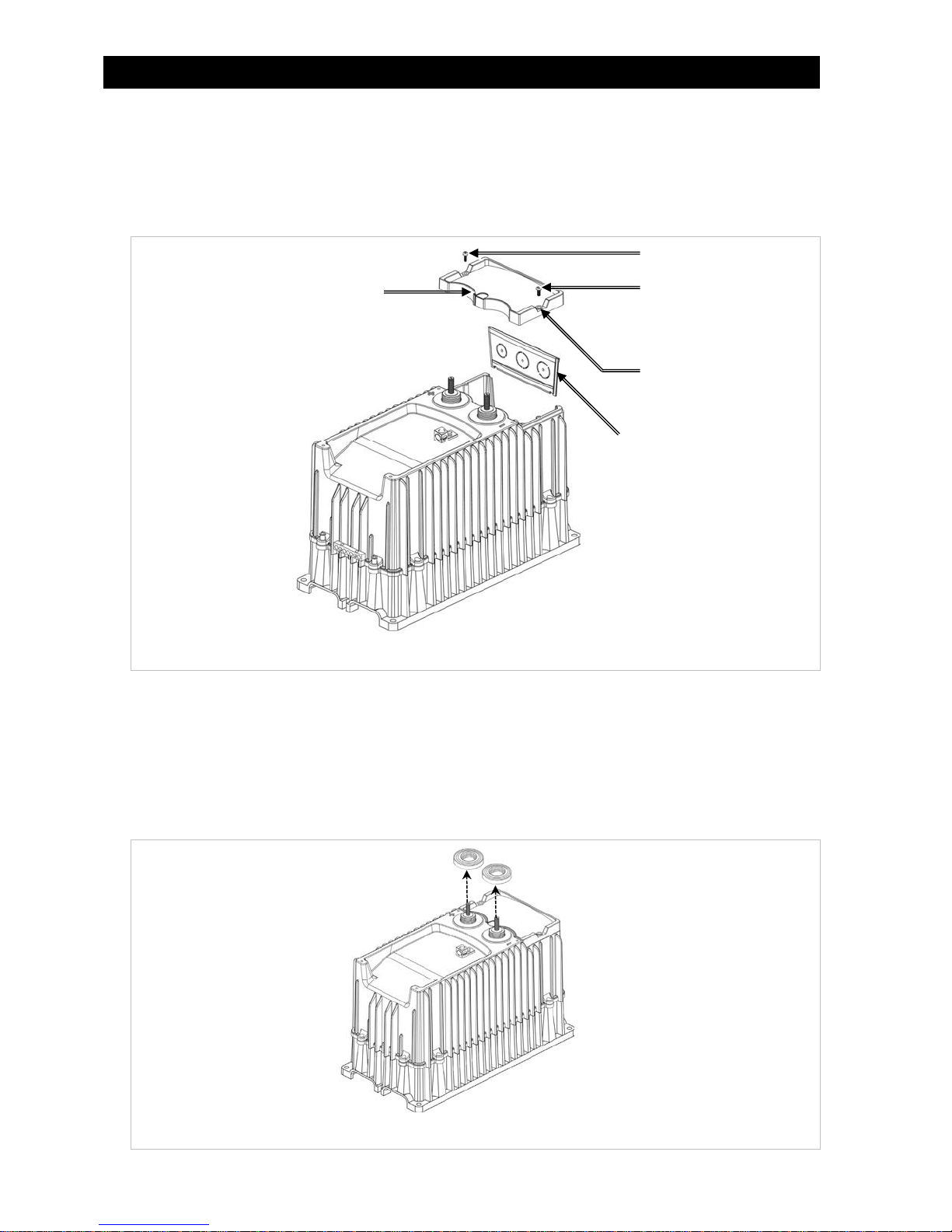
2. Remove the DC Cover or Turbo Fan. Remove the battery terminal covers. Using a #2 Phillips
screwdriver, remove the two screws attaching the AC Cover as shown in Figure 1. Remove the rubber
washers, rubber grommet, and AC Cover as shown in Figure 1.
Screw
Grommet
AC Plate
Screw
Washer
Figure 1 AC Cover & Access Plate
3. Remove the AC Plate. See Figure 1.
4. Disconnect all AC and DC wiring to the inverter. Using a meter, verify that no AC or DC voltage is present.
5. Using the strap wrench, remove the red and black ring nuts located on the battery terminals. See Figure 2.
NOTE: If the ring nuts are too tight, a hammer and flat screwdriver may be used to tap the ring nuts
counterclockwise. A small pipe wrench may be used. Cover the jaws of the wrench with tape to
minimize damage to the plastic nuts.
Ring Nuts
Figure 2 Ring Nuts
2 900-0107-01-00 Rev A
Page 3
Part Replacement Instructions
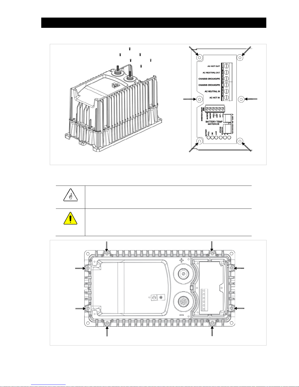
6. Using a #2 Phillips screwdriver, remove the 6 screws located in the AC wiring compartment. See Figure 3.
Screws
Figure 3 AC Compartment Screws
7. Using the 4mm hex wrench, remove all 8 hex bolts that connect the top cover to the bottom chassis of
the inverter. The locations of these bolts are shown in Figure 4.
IMPORTANT:
After removing the hex bolts, read the next step carefully before removing the cover.
CAUTION: Equipment Damage
Inverter components will be damaged if the cover is removed too quickly. The cover
and fan are wired to the internal FET board with a PCB connector. See Figure 5.
8. Carefully lift the inverter cover, just far enough to locate the fan wire.
900-0107-01-00 Rev A 3
Figure 4 Top Cover Hex Bolts
Page 4
FX-Class and FXR-Class
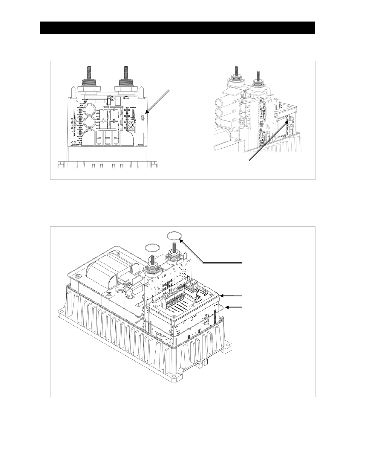
9. Disconnect the fan wire. The connector locations are different for FX-class and FXR-class inverters. The
locations are shown in Figure 5.
PCB Connector
(FX-class)
PCB Connector (FXR-class)
Figure 5 Fan Connector
10. Remove the top cover and set it aside.
11. Remove the O-rings that are seated on the battery terminals. Remove the gasket located on top of the
AC PCBA. See Figure 6.
NOTE: A larger O-ring travels the perimeter of the chassis and may come off during disassembly. If so,
reinstall the O-ring during reassembly.
Battery Terminal O-Rings
AC Compartment Gasket
Inverter O-Ring
12. Remove the two ribbon cables that join all three circuit boards. One cable connects the FET PCBA to the
Control PCBA. The other connects the AC PCBA to the Control PCBA.
To remove the ribbon cables, release the levers on each connector that holds the cable in place. The
locations of the cable connectors are shown in Figure 7 and Figure 8.
4 900-0107-01-00 Rev A
Figure 6 Gasket and O-Rings
Page 5

Part Replacement Instructions
Levers
NOTE: Two other levers are located
below the chassis lip.
Figure 7 FET to Control Ribbon Cable
Levers
NOTE: Two other levers are located
below the chassis lip.
Figure 8 AC to Control Ribbon Cable
13. Gently lift the AC PCBA until there is resistance from the AC output wires connected to the AC
Assembly. Pull out the Control PCBA. See Figure 9.
NOTE: No more disassembly is needed if the Control PCBA is the only board to be replaced.
Lift AC PCBA
Remove Control PCBA
900-0107-01-00 Rev A 5
Figure 9 Removing the Control PCBA
Page 6

FX-Class and FXR-Class
14. Before removing the AC PCBA, using a pair of long-nose pliers, disconnect the white and black AC
output wires connected at the bottom of the board. (See Figure 10 for the location of the wire
connectors.) Remove the AC PCBA.
NOTE: No more disassembly is needed if the AC and/or Control PCBA are the only boards to be replaced.
Transformer Hot (Black)
Transformer Neutral (White)
Gap (see page 8)
Figure 10 AC Output Wires
15. Remove the two bolts that connect the FET PCBA to the transformer. Use the 10mm socket with 12”
extension on bolt #1 and two 10mm wrenches on Bolt #2. See Figure 11.
Bolt #1
FET Bus Bar to
Transformer Bus Bar
FET Idle Arm to Transformer
Bolt #2
Idle Arm
Figure 11 Bolt Removal
16. Remove the thermistor wire from the FET PCBA. Figure 12 shows the location of the connector.
CAUTION: Equipment Damage
The thermistor wire must be disconnected
inverter. Failure to do so will destroy the thermistor wire when it is pulled out. It will
also damage the connections.
6
removing the FET PCBA from the
before
900-0107-01-00 Rev A
Page 7

Part Replacement Instructions
Thermistor
Connection
Figure 12 Thermistor Connection
17. Remove the FET PCBA.
Assembly
The order of assembly depicted here is:
1. FET PCBA
2. AC PCBA
3. Control PCBA
If the FET and or AC boards do not need to be replaced or have not been removed, the installer
may ignore these steps and proceed through the steps that are required. The installer should then
proceed to the testing steps, which begin on page 11.
To assemble the inverter:
1. Check the replacement FET PCBA to see if a thermistor clip was installed. (See Figure 12.) If one is
present, remove it and discard.
2. Guide the FET PCBA into the proper slot of the chassis; lower it only halfway down. Plug the green
thermistor wire from the transformer into the FET PCBA. (See Figure 12 for the location of this
connector.) Push the FET PCBA all the way down into the chassis.
IMPORTANT:
Ensure that the AC wires from the transformer (see step 5) are routed through the gap
on the bottom of the FET PCBA. Routing them elsewhere may pinch the wires and
could cause the inverter to fail.
900-0107-01-00 Rev A 7
Page 8

FX-Class and FXR-Class
3. Before bolting down the FET PCBA, it may be necessary to loosen the bolt that mounts the transformer
bus bar to the transformer. Loosening this bolt will make it easier to align the FET PCBA correctly.
See Figure 13.
Figure 13 Loosen Bolt
4. Once the FET PCBA is aligned, tighten all bolts to a torque value of 72 in-lb.
5. Guide the AC PCBA half way down into the chassis. Attach the AC output wires to their connectors. The
black wire connects to terminal XFMR HOT. The white wire connects to XFMR NEU. See Figure 14 (and
also Figure 10 if necessary) for the location of the wire connectors.
XFMR HOT (Black wire)
XFMR NEU (White wire)
Lip
AC PCBA
Copper Prongs
Lip
Figure 14 AC PCBA and Control PCBA
8
Control PCBA
900-0107-01-00 Rev A
Page 9

Part Replacement Instructions
6. With the AC PCBA lifted as high as possible, guide the Control PCBA into its slot in the chassis. Lower
the AC PCBA over the top of the Control PCBA. As shown in Figure 14, there is a “lip” on the AC PCBA
that fits over the top of the Control PCBA.
IMPORTANT:
Ensure the AC wires from the transformer (see step 5) are routed through the gap
on the bottom of the AC PCBA. (See
pinch the wires and could cause the inverter to fail.
Ensure that the copper prongs on the AC PCBA do not pinch the output wires
when the board is lowered into place.
Figure 10
7. Once each PCBA is seated and secured in the chassis, re-attach the ribbon cables to the boards.
NOTE: FX-class inverters use two identical cables with 34 pins. Ensure that the cables are bent as
shown in Figure 15 so that they can be routed correctly inside the inverter.
NOTE: FXR-class inverters do not have identical cables. Do not confuse them. The cable between the
AC PCBA and Control PCBA has 34 pins. The cable between the FET PCBA and Control PCBA has 40 pins.
Ensure the cables are bent as shown in Figure 15 so that they can be routed correctly inside the inverter.
Red Stripe to Top
.) Routing them elsewhere will
AC to Control
Ribbon Cable
(34 pins)
Red Stripe to Bottom
FET to Control
Ribbon Cable
(34 pins for FX,
40 pins for FXR)
Figure 15 Ribbon Cables
8. Install the ribbon cable that is bent on one end to the FET PCBA and the Control PCBA. (See Figure 16 and
also Figure 7 if necessary.) In the FX inverter, this cable has 34 pins. In the FXR inverter, it has 40 pins.
Make sure the red stripe is oriented toward the top of the chassis. Push down on each end until the levers
click and the plug is secure.
Red Stripe to Top
900-0107-01-00 Rev A 9
Figure 16 FET to Control Ribbon Cable
Page 10

FX-Class and FXR-Class
9. Install the ribbon cable that is bent in half to the AC PCBA and the Control PCBA. (See Figure 17 and
also Figure 8 if necessary.) This cable has 34 pins. Make sure the red stripe is oriented toward the
bottom. Push down on each end until the levers click and the plug is secure.
Red Stripe to Bottom
Figure 17 AC to Control Ribbon Cable
10. Install the gasket between the AC PCBA and the top cover. This gasket is used to keep water out. Make
sure to line up the holes on the gasket with the holes in the AC PBCA. See Figure 18.
Battery
Terminal O-Rings
AC
Compartment
Gasket
11. Install the two small O-rings on the FET PCBA battery terminals. See Figure 18.
12. If the large chassis O-ring is out of position, re-seat it into the groove on the chassis. See Figure 18.
10 900-0107-01-00 Rev A
Inverter O-Ring
Figure 18 Gasket and O-Rings
Page 11

Part Replacement Instructions
Testing
Before reinstalling the top cover, the inverter should be tested to ensure it was assembled correctly.
To test an assembled inverter:
1. Connect a DC power supply to the inverter. Use an appropriate voltage for the inverter under test (12
volts, 24 volts, etc.). 9-volt batteries may be used if a power supply is not available. For a 12-volt or
24-volt model, use three 9-volt batteries in series. For a 48-volt unit, use six 9-volt batteries in series.
2. The inverter will go through a boot-up routine. The red LOW battery LED indicator will illuminate. It will
then be replaced by the yellow OK indicator and possibly the green FULL indicator.
3. The fan, if plugged in, will come on. The fan does not need to be plugged in for testing, but the ERROR
indicator will illuminate if the fan is not present.
4. The FX inverter is defaulted to the On state. The FXR inverter is defaulted to the Off state. Turn the FXR
inverter on with the MATE3 system display, or remove and replace the ON/OFF jumper as shown in the
Installation Manual. (Perform this with the FX inverter as needed, if it is not already on.)
5. After a few seconds the inverter should produce AC voltage, accompanied by the green INVERTER
indicator. Check the output terminals with a DVM or voltmeter to confirm the presence of voltage. The
AC voltage reading should be appropriate for the inverter model.
6. Once the inverter power-up sequence is confirmed, disconnect the DC power supply.
7. The test is successful if the inverter completed each routine. If this did not occur, it may be necessary to
contact OutBack technical support for troubleshooting.
Completion
To finish reassembly:
1. Connect the fan cable. See Figure 19 and also Figure 5 if necessary. In the FXR inverter, the cable should
be routed through notches in the AC and FET PCBA. Routing them elsewhere may pinch the cable.
PCB Connector (FX-class)
PCB Connector (FXR-class)
Figure 19 Fan Connector
2. Place the top cover over the chassis so that the battery terminals protrude through the holes in the cover.
Ring
Screws
Nuts
Figure 20 AC Compartment Screws
3. Insert, but do not tighten the 6 screws that connect the top cover to the AC Assembly. See Figure 20.
4. Reattach the red and black battery terminal nuts and tighten. Next tighten the 6 AC Assembly screws to
a torque value of 15 in-lb. See Figure 20.
900-0107-01-00 Rev A 11
Page 12

FX-Class and FXR-Class
5. Install the 8 hex screws that attach the top cover to the chassis. Tighten to a torque value of 36 in-lb.
See Figure 21.
Figure 21 Top Cover Hex Bolts
6. If replacing the Control PCBA in a sealed FXR-class inverter, it must be re-programmed for that model.
(The default setting is for a vented model.) Apply battery power to the inverter. Using the MATE3, press
the “LOCK” button, press the “UP” button, and insert the “Installer” password. The default password is
[1][7][3][2] but may have been changed. If necessary, contact the installer or OutBack technical support.
Press the center button, select “Inverter”, scroll down to “Model Select”, press the center button, and
then change the model to the correct (sealed) version. The results of this model change will take effect
within 1 minute of making this change. Please allow this amount of time to pass without making any
further changes to settings.
This completes the procedure for replacing circuit boards in the FX-class or FXR-class inverters.
Recycling Parts
Use the box from the new circuit boards to return the old boards to OutBack Power Technologies
for recycling, or use a local recycling service. Do not throw the old circuit boards into the garbage.
Ship the old circuit boards to:
OutBack Power Technologies
RMA#_________________________
17827 – 59th Avenue NE
Arlington, WA 98223, USA
Contact Information
Address: Corporate Headquarters
17825 – 59th Avenue N.E.
Suite B
Arlington, WA 98223 USA
Telephone:
Email: Support@outbackpower.com
Website: http://www.outbackpower.com
+1.360.435.6030
+1.360.618.4363 (Technical Support)
+1.360.435.6019 (Fax)
European Office
Hansastrasse 8
D-91126
Schwabach, Germany
+49.9122.79889.0
+49.9122.79889.21 (Fax)
Notice of Copyright
FX-Class and FXR-Class Inverter/Charger Service Instructions © January 2015 by OutBack Power Technologies. All Rights Reserved.
Part Number
900-0107-01-00 Rev A
12 900-0107-01-00 Rev A
 Loading...