

Page 1

1000
User’s Guide
Includes Mounting, Installation, and
Product Registration
Page 2

OutBack Power Systems FLEXware is a system of modular aluminum mounting hardware and installation
components designed for convenient system installation and integration.
About OutBack Power Systems
OutBack Power Systems is a leader in advanced energy conversion technology. Our products include
true sine wave inverter/chargers, a maximum power point charge controller, system communication
components, as well as breaker panels, breakers, accessories, and assembled systems.
Notice of Copyright
FLEXware 1000 Manual Copyright © 2006 All rights reserved.
Disclaimer
UNLESS SPECIFICALLY AGREED TO IN WRITING, OUTBACK POWER SYSTEMS:
(a) MAKES NO WARRANTY AS TO THE ACCURACY, SUFFICIENCY OR SUITABILITY OF ANY TECHNICAL OR
OTHER INFORMATION PROVIDED IN ITS MANUALS OR OTHER DOCUMENTATION.
(b) ASSUMES NO RESPONSIBILITY OR LIABILITY FOR LOSS OR DAMAGE, WHETHER DIRECT, INDIRECT,
CONSEQUENTIAL OR INCIDENTAL, WHICH MIGHT ARISE OUT OF THE USE OF SUCH INFORMATION. THE
USE OF ANY SUCH INFORMATION WILL BE ENTIRELY AT THE USER’S RISK.
Date and Revision
September 25, 2006 1.0
Contact Information
OutBack Power Systems
19009 62nd Ave. NE
Arlington, WA 98223
Phone (360) 435-6030
Fax (360) 435-6019
www.outbackpower.com
Page 3

Requirements and Warnings
The OutBack FLEXware 1000 enclosures (FW1000-AC and FW1000-DC) are listed by ETL as an
indoor enclosure to UL standard UL 508A Industrial Control Panels.
This enclosure is intended for battery circuits congured for 12 to 48 volts nominal.
Grounding Instructions – Each enclosure should be connected to a grounded, permanent wiring
system. For most installations, the negative battery conductor should be bonded to the ground-
ing system at one (and only one) point in the DC system. All installations should comply with all
national and local codes and ordinances. System grounding as required by the National Electric
Code, ANSI /NFPA 70-1996, is the responsibility of the system installer.
The equipment ground on FLEXware1000 is marked with this symbol:
FLEXware is designed for indoor mounting only with appropriate fasteners and a secure mounting
surface that can handle the full weight of an assembled system.
Page 4

Welcome to OutBack Power Systems’ FLEXware
FLEXware is a convenient all-aluminum power system oering simpler, code-compliant installation
of OutBack power electronics components. Three versions of FLEXware are available:
• FLEXware 250 for single FX Series Inverter/Charger installations along with the desired AC and
DC disconnects
• FLEXware 500, which supports up to two FXs and two MX Charge Controllers, accommodating
both split-phase and/or higher power output as needed
• FLEXware 1000 accommodates up to four FXs and four MX Charge Controllers
Please Note: Both the FLEXware 500 and the FLEXware 1000 power systems provide locations for
FW-X240 Auto-Transformers, multiple DC shunts and other essential components required in
higher kW systems.
1
Page 5
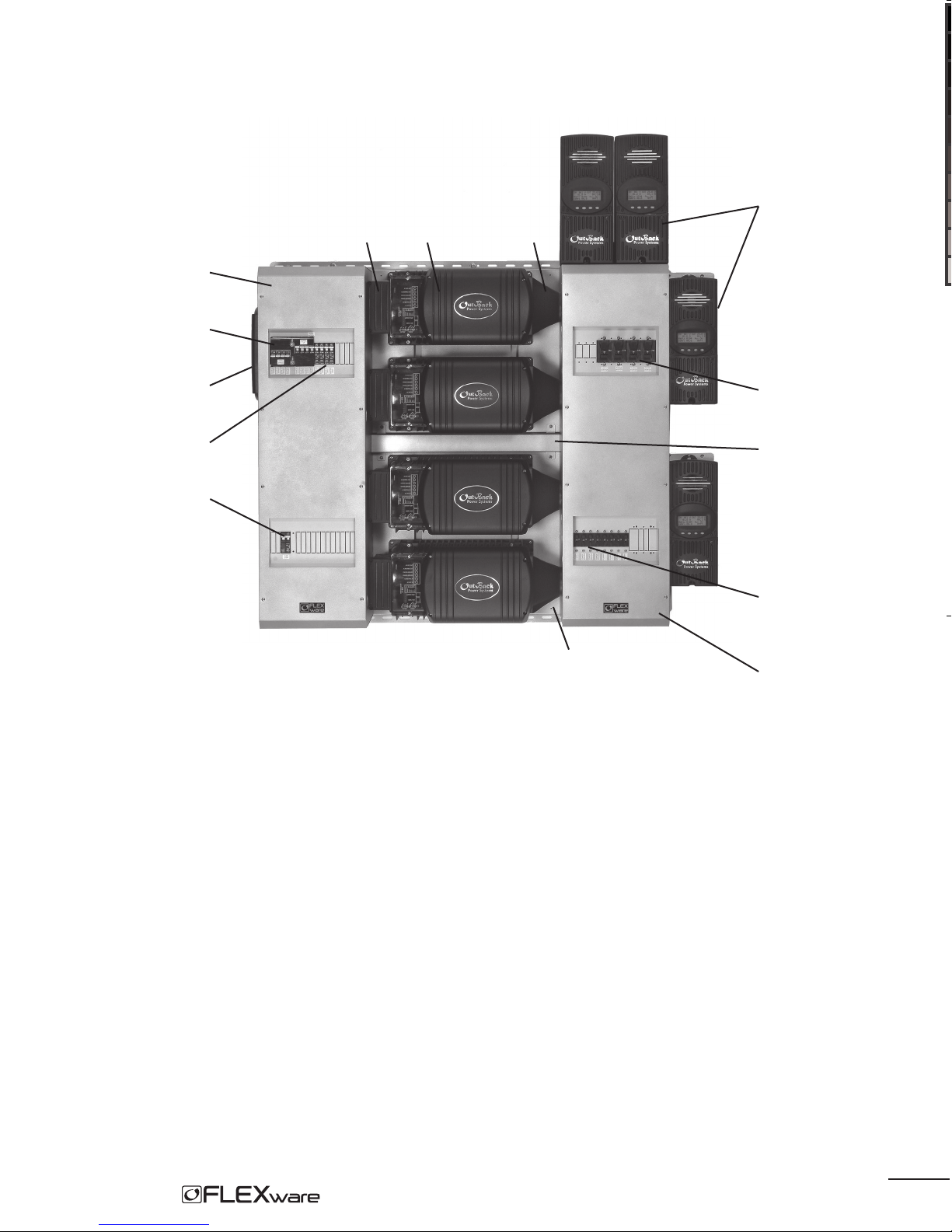
Getting to Know FLEXware 1000
FW1000-AC
IOB Kit
MX60s
ACA FX (with DCC) DCA
HUB
AC Breakers
FW-X240 Breaker
Figure 1: FLEXware 1000 System
FW-MP
DC Breakers
Wiring Raceway
PV+ and Bat+
breakers
FW1000-DC
2
Page 6

Knockouts and Dimensions
Figure 2: Front View Side View
3
Page 7

A complete FLEXware 1000 System consists of the following in addition to the FW1000-AC
and FW1000-DC:
• two FLEXware Mounting Plates (FW-MP)
• FLEXware Wiring Raceway (included with AC chassis)
• four FX Series Inverter/Chargers
• AC Conduit Adapter (ACA) and a DC Conduit Adapter (DCA), which connect each FX to the
FW1000-AC and FW1000-DC
• MX60 Charge Controller(s) (normally part of this system) and mounting brackets
• AC and DC breakers including a specic AC Input/Output/Bypass Breaker (IOB) Kit
• bus bars and DC current shunts as required per specic installation
• DC and AC ground fault protection
Some systems will work optimally with a FW-X240 Auto-Transformer installed.
Note: Be sure you have all the parts required for your intended system installation. As every
installation is dierent, consult with your dealer or installer for further information.
FLEXware 1000 Parts List
FLEXware 1000 consists of the FW1000-AC and FW1000-DC. Each is an aluminum chassis for
mounting AC and DC breakers, respectively, along with the components listed below:
FW1000-AC components:
FW1000-DC components:
• aluminum enclosure
• DIN rail bracket
• TBB-GROUND
• Breaker and Bypass Mounting Bracket
• FW Wiring Raceway with mounting hardware
• metal hanging straps for combining
two FW-MPs
• aluminum enclosure
• 500 amp shunt with TBB
• TBB-GROUND
• one FW breaker bus
• two shunt bus bars
• two DC Breaker Mounting Brackets
• FXW1000-DC Hardware Kit
4
Page 8

Installation Tips
• Never use less than the minimum recommended number and type of fasteners when installing
the FLEXware Mounting Plates.
• Each FX weighs in excess of 50 lbs and is often more easily installed by two people rather
than one.
• Be sure the DC enclosure is secured to the FLEXware Mounting Plate before attaching the
MX Charge Controller to it.
• Installation of each enclosure and breakers is normally easier by removing the breaker brackets
rst. Do not remove any breaker knockouts from these brackets without referring to the chosen
AC IOB kits and DC breaker selections rst.
• It is also easier if all conduit knockouts are removed before mounting the enclosures.
Mounting and Installation
FLEXware 1000 is designed for mounting on the FLEXware Mounting Plate (FW-MP). Although the
components can be secured to other surfaces, the FW-MP is an engineered platform designed
for the FLEXware 1000 installation. This manual illustrates such an installation. OutBack does not
endorse other installation methods and therefore cannot recommend fasteners or other means of
attachment due to the variety of installations possible in the field.
Please see the FLEXware Mounting Plate Instructions for further information.
In addition to installing the AC and DC chassis, a typical installation includes four FX Series Invert-
er/Chargers, one or more MX Charge Controllers, a HUB Communications Manager, and AC and
DC Conduit Adapters. The installation of these components is also displayed in these instructions.
Slot indicates this is the top edge of the FW-MP
T
Figure 3: FLEXware Mounting Plate
5
Page 9

Hanging Straps
Figure 4: Two mounting plates installed
Note: Check that both FW-MPs are level as per the FLEXware Mounting Plate Installation Manual. If
space is restricted, the FW-MPs can be installed vertically.
With the Mounting Plate and the hanging screws (for the FX Series Inverter/Chargers) installed,
install the FXs.
• Start with the top FX.
• Hang the FX on the hanging screws, but continue to hold onto it.
• Loosely install four M6 X 20 mm screws, included with the FW-MP, one in each corner; tighten
them when all four are installed and the FX is aligned.
• Install the remaining FXs in the same manner.
6
Page 10

Figure 5: Four FXs installed on FW-MPs
Note: The hanging straps are now removed.
7
Page 11

Installation of the AC Chassis and DC Chassis
After the FXs are installed, mount the AC chassis and the DC chassis in either order.
Figure 6: It is easier to remove the appropriate side knockouts from both the AC and DC chassis
before installing either of them. If needed, the back knockouts must be removed before installation.
8
Page 12

When installing the AC chassis and the DC chassis:
• Either chassis can be installed rst, the order is not important.
• Only loosely install the eight screws securing each chassis. The screws will be tightened later.
To install the chassis:
• Hold each chassis up to its respective mounting holes on the FW-MP.
• Place the, M6 X 10mm machine screws through the chassis and into the holes shownin Figure 7
tightening only enough to keep the chassis in place.
AC side DC side
AC chassis
Mounting Holes
Figure 7: Chassis Mounting Holes
DC chassis
Mounting Holes
9
Page 13

Figure 8: AC and DC Chassis mounted
With each chassis loosely mounted, the AC Conduit Adapter (ACA) and DC Conduit Adapter (DCA)
are installed on the FX.
• Remove the clear plastic AC cover and AC Conduit Plate from each FX.
DC Wiring
Cover (DCC)
Clear plastic AC cover
AC Conduit Plate
Figure 9: FX Series Inverter/Charger
10
Page 14

• Line up either the ACA or DCA (conduit adapters) on its respective side of an FX, starting at
the top.
• To attach a DCA, line up its two screw holes with the upper and lower right DCC screw holes.
• When lined up, loosely install the upper screw to hold the DCA in place (screw can be removed
later when the DCC is installed).
• Slide the DC chassis over snug against the DCA (the screw slots in each chassis are oval-shaped
to allow for movement) so the DCA lines up with the conduit adapter hole on the chassis.
• Install the plastic bushing in this hole (see Figure 11).
• Install the remaining DCA(s) in this same manner. After inserting the bushing into the top DCA,
the remaining DCA(s) will line up and the other bushings can be installed.
• With all the DCA’s aligned with the DC chassis and the bushings installed, tighten the DC chassis
screws against the FW-MP.
Each ACA ts against the AC chassis. A single screw holds the DCA Conduit Adapter in place.
Slide the DC chassis against each DCA to line it up with
the plastic bushing.
ACA
DCA
Figure 10: ACAs (left) and DCAs (right) in place
11
Page 15

Plastic bushing,
DC side
Figure 11: DCA bushing
Note: The DCA will be held rmly in place when the DCC (FX cover) is secured at the end of
the installation.
To install an ACA:
• Follow the separate ACA instructions for mounting to the FX.
• Line the ACA up with the conduit hole in the AC Chassis.
• When aligned, move the AC chassis snug against the ACAs after the ACA installations.
• Press a 1” plastic bushing from inside the AC chassis out to the ACA through each previously
removed knockout, sliding the AC chassis against the ACAs until snug.
• With all the ACA’s aligned with the AC chassis and the bushings installed, tighten the AC chassis
screws against the FW-MP.
With both the AC chassis and DC chassis installed, the breaker brackets, AC din rail(s), and
optional AC and DC breakers can be installed. Please see the individual Input/Output/Bypass
Breaker (IOB) kit for instructions.
12
Page 16

MX60 Installation
A FLEXware 1000 System installation includes up to four MX Charge Controllers which can be
mounted on both the top and side of the FW1000-DC. Newer MXs have rear knockouts allowing
them to be mounted directly to the side of the enclosure without the need for additional
mounting brackets. Mounting brackets are required for top installation of all MX models and for
side installation of less recent models..
Bracket screw locations are
shown below
Screw locations for directly attaching an
MX Charge Controller are shown below
Figure 12:
MX Charge Controller mounting options
13
Page 17

MX Knockouts
Charge
Controller
knockouts
Figure 13:
MX Charge Controller 1” knockouts
The MX Charge Controller attaches
to the chassis using three #10 X 3/8”
sheet metal screws included in the
hardware kit. Two are inserted from
inside the MX and the third through
the hanger on the top of the MX.
14
Page 18

Figure 14: FLEXware Wiring Raceway
When all component and cabling installations are complete, install the FLEXware Wiring Raceway
to cover and protect the exposed communication cables running between the AC and DC sides
of the system. The illustration above shows FLEXware Mounting Plates with components removed
for clarity.
15
Page 19

Installing an OutBack HUB
An OutBack HUB allows the FX Series Inverter/Chargers, MX60 Charge Controllers, and MATE
to communicate with each other. It attaches (see arrows in Figure 14) to the outside of the
FW1000-AC (hardware included with the HUB).
HUB connection
Figure 14: OutBack HUB
16
Page 20

Figure 15: Wiring Diagram
17
Page 21

Page 22

Page 23

Product Registration
Please take a moment to register and provide us with some important information. Send to:
OutBack Power Systems, 19009 62nd Avenue NE, Arlington, WA 98223 USA.
Name: ________________________________________________________________________
Address: ______________________________________________________________________
City, State, Zip Code: _____________________________________________________________
Country: ______________________________________________________________________
Telephone Number: _____________________________________________________________
E-mail: ________________________________________________________________________
Sold by: _______________________________________________________________________
Installer: ______________________________________________________________________
Purchase Date: _____________________ Model Number: ______________________________
Serial Number: _________________________________________________________________
Check all that apply:
m O-Grid Installation m Grid-Tie Installation m Residential Installation m Commercial Installation
Page 24

19009 62nd Avenue NE
Arlington, WA USA
(+1) 360-435-6030
European Sales Office
Barcelona, España
(+34) 600-843-845
www.outbackpower.com
900-0062-1
 Loading...