

Page 1
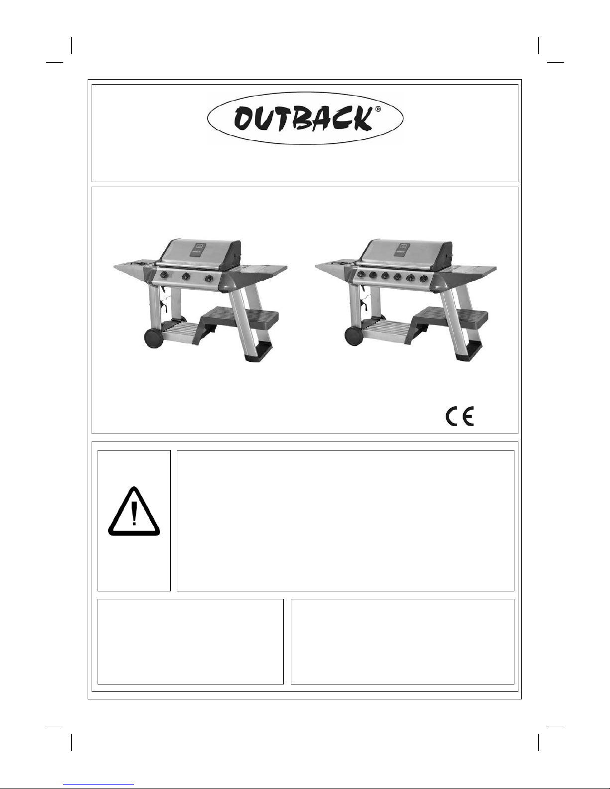
Assembly and Operating Instructions for Outback®
Excelsior 3 Burner and Excelsior 6 Burner Gas Barbecues
Photographs ar e not t o sc al e.
Specifications subject to change
without prior notice.
WARNING
• For outdoor use only.
• Read instructions before using the appliance. Failure to follow instructions
could result in death, serious bodily injury, and/or property loss.
• Warning: accessible parts may be very hot. Keep young children away.
• Do not move the appliance during use.
• Turn off the gas supply at the gas bottle after use.
• Do not change the gas bottle when the appliance is hot.
• Any m odi fi cat i on of th e ap pli anc e, m is us e, or fai lu re t o fo ll o w the i ns tr uct io ns
may be dangerous and will invalidate your warranty. This does not affect your
statutory rights.
• Retain these instructions for future reference.
• Leak test your barbecue annually. Check the hose connections are tight and
leak test each time you reconnect the gas bottle.
FOR YOUR SAFETY
If you smell gas:
1. Shut off gas to the appliance.
2. Extinguish any open flame.
3. Open barbecue lid or hood.
4. If odour continues, discontinue use and
contact your local dealer.
FOR YOUR SAFETY
1. Do not store or use petrol or other flammable
vapours or liquids in the vicinity of this or any
other appliance.
2. A gas bottle not connected for use shall not be
stored in the vicinity of this or any other
appliance.
0359
Page 2

2
CODE PART QTY
Outback® Exce lsior
3 Burner
Outback® Exce lsior
6 Burner
HOOD
A1 Hood Handle 1
A2
Hood (Pre-Assembled to Body)
1
A3 Hood Panel 1
A4 Heat Indicator and Nuts 1
BODY
B1 Barbecue Body 1
B2 Burner
3 6
B3 Control Panel 1
B4 Knob
3 6
B5 Drip Tray 1
B6 Drip Tray Left Bracket 1
B7 Drip Tray Right Bracket 1
B8 Flame Tamer
2 4
B9 Large Cooking Grill 1
B10 Small Cooking Grill 1
B11 Cooking Griddle 1
B12 Hose and Regulator Assembly 1
B13 Warming Rack 1
TROLLEY
C1 Side Burner Shelf 1
C2 Side Shelf Shield 1
C3 Front Left Endcap 1
C4 Rear Left Endcap 1
C5 Utensil Tray 2
C6 Side Shelf 1
C7 Right Insert 1
C8 Left Front Leg 1
C9 Left Rear Leg 1
C10 Right Front Leg 1
C11 Right Rear Leg 1
C12 Bottom Slat Assembly 1
C13 Base Tray 1
C14 Gas Bottle Holder 1
C15 Trolley Foot 1
C16 Hubcap 2
C17 Wheel 2
C18 Axle 1
C19 Retaining Rod 1
C20 Gas Bottle Strap 1
C21 Side Shelf Hook 2
C22 Fixing Bracket 2
C23 Side Burner Grid 1
HARDWARE
D1 M4x15 Bolt 4
D2 M5x15 Bolt 4
D3
Ø5 Washer
4
D4 M5 Nut 4
D5 M6x15 Bolt 24
D6
Ø6 Washer
4
D7 M6x35 Bolt 16
D8 1/4-20UNCx12 Bolt 6
D9 Locknut 2
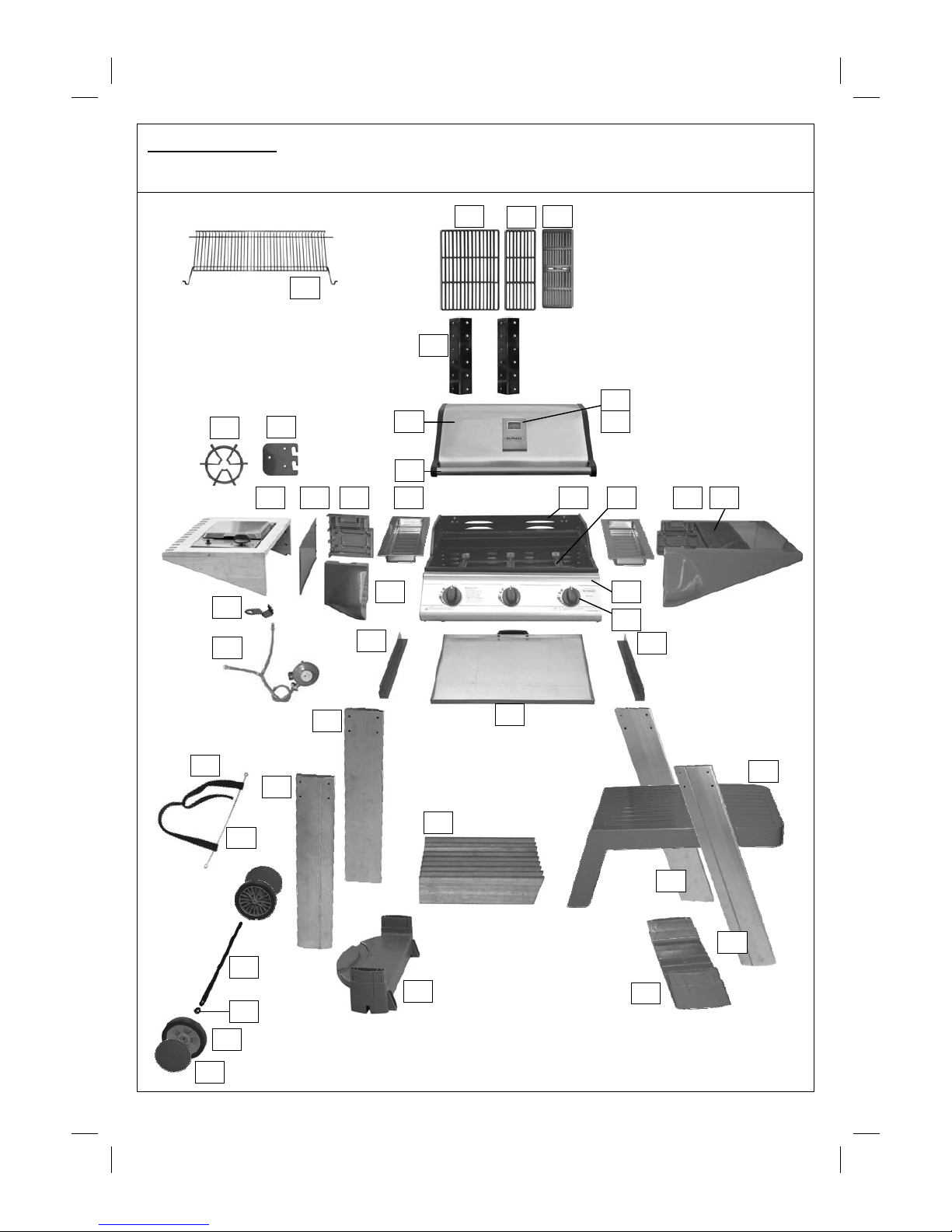
Parts List
Quantities vary according to model purchased. Specifications subject to change without prior notice. For more
details on hardware, pl ease see ‘Hardware Reference Diagr am’.
Pre-Assembled Component
Quantit y varies acc or di n g to model purc h as ed
Appearance, si z e, an d c ons tr uc t ion may differ acc ordin g t o m od el purc h ased
Page 3
3
Parts Diagrams
Quantities vary according to model purchased. Specifications subject to change without prior notice. For more
details on hardware, pl ease see ‘Hardware Reference Diagr am.’
B8
C2
B3
B4
B5
B2
C3
C5 C4 C1
A2
C12
B11 B9
C15
C14
C16
C17
D9
C18
C9
C8
C11
C20
C19
C7
C10
A4
A3
B1
C13
C21
B12
C22
B6
B7
B10
A1
C23
C6
B13
Page 4
4
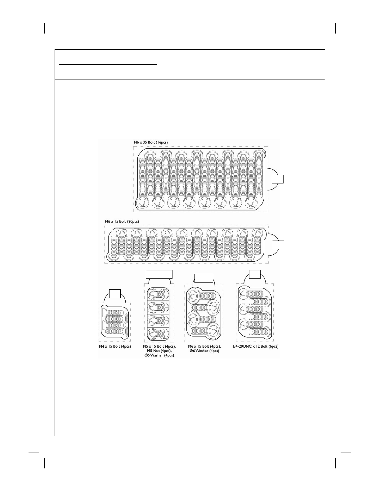
Hardware Reference Diagram
Specifications subject to change without prior notice.
D1
D5
D2,D3,D4
D5,D6
D7
D8
Page 5
5
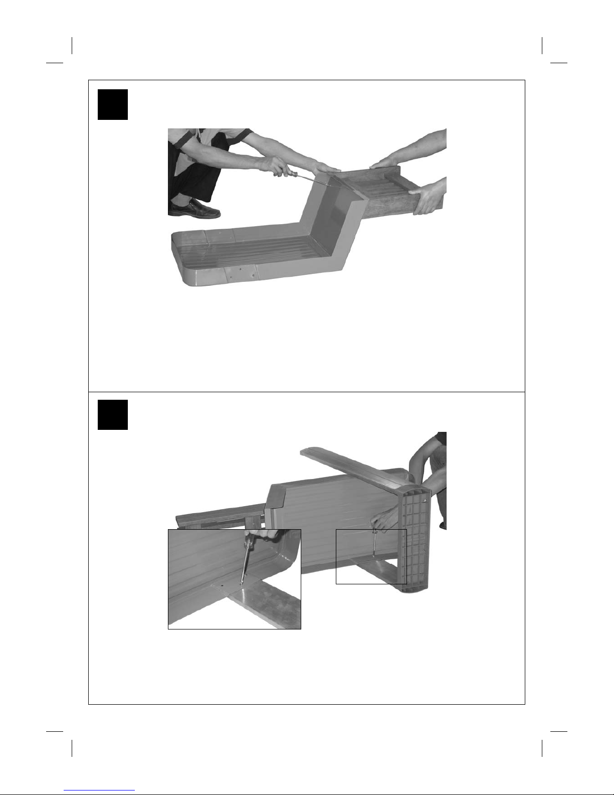
Attach t he Ri ght Front L eg (C10) to t he Tr olley Foot ( C15) .
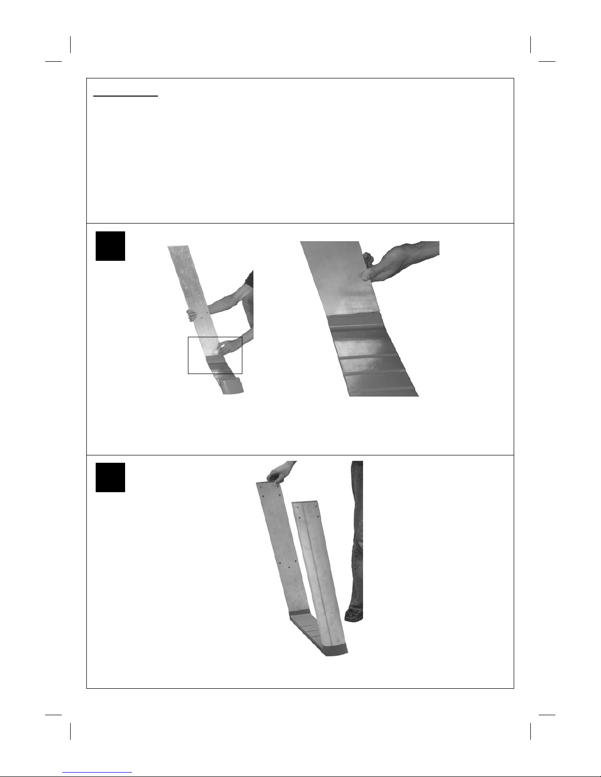
4. Assembly
IMPORTANT!
• Tools Required: Medium size flat blade or Phillips/Crosspoint screwdriver, adjustable spanner or metric
spanner set
• The assembly of this barbecue requires 2 people.
• Carefully unpack the parts from the box and remove all internal packaging before commencing assembly. All
loose items including the grills, griddle, flame tamers and warming basket must be removed from the body.
• The inlet connection of the gas rail assembly on the BBQ body is lower than the body. You must never allow
the pi pe to r est on t he grou nd dur ing a ssem bly as s eriou s dama ge coul d res ult. W e recom mend t he body is
left sitting in the box until required for assembly to trolley.
• Whilst every care is taken in the manufacture of this product, care must be taken during assembly in case
sharp edges are present.
2
Attach the Right Rear Leg (C11) to the Trolley Foot (C15). The leg is a push fit onto the trolley foot and on
the g as b ottl e hol d er. I n cas e of diff ic ult y, t hey may n eed t app in g li ghtl y wi th a soft f ac e mall et . Ta ke c are
not to damage parts.
1
Page 6
6
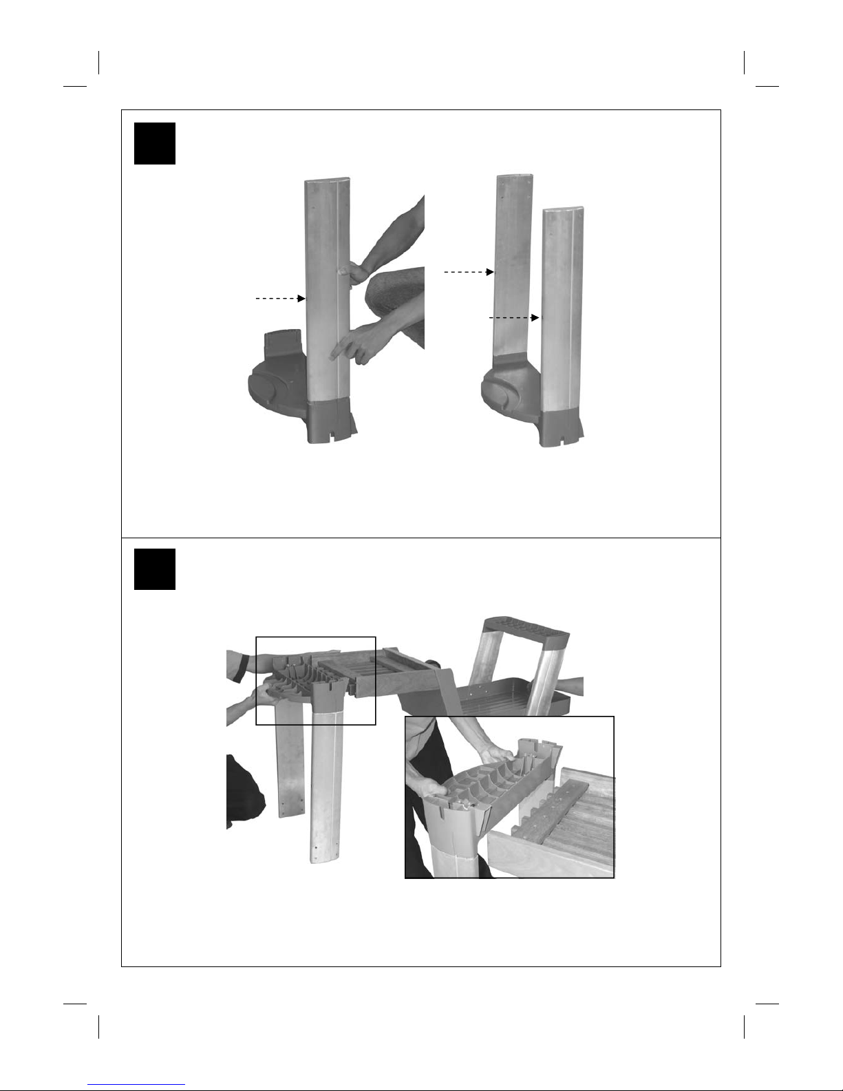
Attach the Bottom Slat Assembly (C12) to the Base Tray (C13) using the M6x15 Bolts (D5).
Attach the leg assembly to the Base Tray (C13) using the M6x15 Bolts (D5).
4
3
Page 7
7
Align the Gas Bottle Holder (C14) with the Bottom Slat Assembly (C12).
Attach the Left Front Leg (C8) and Left Rear Leg (C9) to the Gas Bottle Holder (C14).
Note: Threaded inserts must be facing in the direction shown!
Threaded
Insert
6
5
Page 8

8
Attach th e Gas Bottle Hold er (C14) to the Botto m Slat As s embly (C12) u sing the Screws
(D2) and Washers (D3).
Unscrew the L ocknuts (D9) from both ends of t he Axl e (C19).
Insert the axle through the clamping brackets into the Gas Bottle Holder (C14) and tighten the clamp
screws. Take care not to over tighten these screws which will damage the plastic gas bottle holder.
8
7
Attach the Gas Bottle Holder (C14) to the Bottom Slat Assembly (C12) using M6x15 Bolts (D5)
and Ø6 Washers (D6).
Page 9

9
Sli de th e Wheel s ( C17) over ea ch en d of the axl e. S ecur e the w heel s i nto p lace w ith the
locknuts.
10
9
Carefully turn the completed trolley over, right side up.
Page 10

10
Remove all cooking components, flame tamer, and any internal packaging from the Barbecue
Body (B1).
Carefully turn the barbecue body upside-down.
CAUTION! Care must be taken to ensure the hood does not fall open unexpectedly or
becomes damaged when it is set on the ground.
Attach the Side Shelf (C6) to the barbecue body using M6x15 Bolts (D5).
12
11
Place th e wheel H ubc aps ( C 16) on to th e outs ides of the wheels.
Page 11

11
Attach the Rear Left Endcap (C4) to barbecue body using the M6x15 Bolts (D5).
14
13
Attach the Front Left Endcap (C3) to barbecue body using the M6x15 Bolts (D5).
Page 12

12
Carefully place the barbecue body onto the tops of the legs. The tops of the legs should slot into the
endcaps. When done correctly, the barbecue should be able to stand on its own weight.
WARNING: DO NOT RELEASE THE BARBECUE BODY WHILE THE BARBECUE HAS NOT BEEN
PROPERLY SEATED. THIS MAY RESULT IN INJURY OR DAMAGE TO YOUR BARBECUE.
16
15
Carefully turn the Barbecue Body (B1) over right-side-up.
CAUTION! Care must be taken to ensure the hood does not fall open unexpectedly or
becomes damaged when it is set on the ground.
Page 13

13
Attach the Side Shelf Shield (C2) to the endcaps using the M4x15 Bolts (D1).
18
17
Secure the Legs (C8, C9, C10, C11) to the Endcaps (C3, C4) and the Side Shelf (C6) using M6x35 Bolts
(D7).
Page 14

14
Lay the Utensil Trays (C5) into their positions on either side of the barbecue body.
20
19
Attach the Side Shelf Hook (C21) to the Side Burner Shelf (C1) using the 1/4-20UNCx12 Bolts
(D8), Hook the side burner shelf to the endcaps. Unscrew the retaining screws loosen the preassembled Fixing Brackets (C22). Hook the brackets to the barbecue side shelf shield, retighten
the screws.
Page 15

15
22
21
Attach Drip Trip Left Bracket (B6) onto Barbecue Body (B1) by inserting M5x15 Bolts (D2) through
Ø5 Washers (D3), drip trip left bracket, left sidewall of body and secure with M5 Nuts (D4). Repeat
above process for Drip Trip Right Bracket (B7).
NOTE: Ensure that the tabs of the brackets which stop the drip trip are located at the front
of the barbecue.
Slide the loops of the Gas Bottle Strap (C20) onto the Retaining Rod (C19). Secure the rod to the
trolley legs using the M6x15 Bolts (D5).
Ensure the strap is threaded through the buckle correctly. It must hold the gas bottle firmly in place
onto the barbecue.
Page 16

16
Carefully lay the Flame Tamers (B8) into the barbecue body ensuring it lies level within the
body. Lay the Grills (B9, B10) and Griddle (B11) into place.
3 burner model configuration: Left — Large Cooking Grill, Middle — Small Cooking Grill,
Right — Small Griddle Plate.
NOTE: Ensure that the flame tamer lies directly underneath the grills.
23
24
Insert the Drip Tray (B5) by sliding it underneath the barbecue body.
Page 17

17
25
Place the Side Burner Grid (C23) onto side burner shelf as shown.
Insert the Warming Rack (B13) into the hood and barbecue body. Make sure that the swing
legs fix to the body of the barbecue and the shorter fixed legs go through the holes in the
hood.
26
Page 18

18
Sock the joint of Hose and Regulator Assembly (B12) with jubilee clip onto hot water for 2 minutes, then
connect it to the gas inlet of barbecue and secure by tightening the jubilee clip.
Connect the brass joint onto side burner. Ensure the mating faces of the connection are clean and not
damaged. Do not use any sealing tape, paste, or liquid on the joint. The nut must be tightened with the
use of a spanner. Do not use force which may damage the assembly.
Asse m b ly is now comp lete .
All joints and connections must now be leak tested before using the barbecue.
For more details, please refer to leak testing instructions.
Num ber of valves to be leak tes ted will v ary with model of barbecue.
27
26
Page 19

19
nESSENTIAL INFORMATION
Please read instructions before using your barbecue.
BEFORE YOU USE YOUR BARBECUE (also see installation)
• Perform a leak test. This is the only safe and sure way to detect any gas leaking from joints and
connections of the barbecue after assembly. Follow the leak test instructions. Check that the gas hose is
free of any tension, twisting, cuts, or cracks.
• Make sure your barbecue is in a safe place. It must be outdoors, on level ground and not below ground
level. Ensure that the barbecue is at least 1 meter away from any flammable materials, including trees and
fences and that there are no heat sources near the barbecue (cigarettes, open flames, spark etc.)
• Check that you have the correct gas bottle and regulator for your barbecue (see recommendations in the
Gas and Regulator section of this manual) and that the gas bottle is placed correctly in the gas bottle
holder provided. Never place the gas bottle directly underneath the barbecue.
GETTING STARTED (also see operation)
• Open the hood of your barbecue. Never light your barbecue with the hood closed. Turn the gas regulator or
gas bot tle va lve to t he “O n” P o sition. P ush in th e con tro l knob o f the b u rner you w ant to lig ht an d turn it an ti
clockwise until resistance is met. Wait 4 seconds and then continue turning the control knob until a click is
heard. If the burner does not light, turn of the gas by pushing and holding in the control knob at the High
position and turning to “Off”. The lighting sequence can then be repeated 4-5 times until the burner is lit.
Ignite any of t he remaining burner s in any order, as needed. Confir m each burner is lit before igniti ng another
burner. If any burner fails to ignite after following the above procedure, turn all the knobs to the “Off” position.
Shut the gas off at the gas bottle or regulator. Wait 5 minutes before reattempting the above lighting
procedure. If the barbecue still fails to light, please refer to the manual li ghting instructions.
• Once the burners are li t, turn all the burne rs to the high se tting for 3-5 minutes to pre -heat the barbecue. This
should be done before each session. When pre-heating is complete, cooking can begin taking extra care if
the burners are used in the high position.
• To prevent food sticking we re com m end that you use a long handled brush to apply a light coat of cooking oil
to the gr ills and griddles before e ach barbecue session.
• Side Burner - Open the lid of the side burner. Never light the side burner with the lid closed. Turn the gas
regulator or gas bottle valve to the ‘on’ position. Push the side burner control knob in and turn it to the high
position. Push and hold in the igniter button in the centre of the control panel for 4 to 5 seconds to light the
burner . IF THE BURN ER FAILS TO L IGHT, TURN OFF THE GAS AT THE BU RNER, WA IT 5 MINUTES
AND TRY AGAI N. If the burner cannot be lit using the igniti on syste m, turn to t he manual lighting instruct ions.
• If a fat fi re shoul d occur dur ing cooking, and if safe to do so, turn off t he burner s and the gas at the gas bottle
and wait for t he fire t o go out. Do not pull out the dr ip tray or douse with water.
• Never douse a barbecue with water.
• Never move a barbecue when lit.
• Never leave a lit barbecue una ttended
• Never handl e hot par ts with unprotected ha nds
• Keep children, animals, and elderly pe ople a s afe distance from a lit barbecue .
WHEN YOU HAVE FINISHED COOKING (also see Maintenance)
• Turn all the burners to the high position for 3 to 5 minutes to burn off any food residue from the cooking
surfaces and burners. When the barbecue has cooled, the burnt residue can be removed from the grills,
griddle and flame tamers using a plastic scraper or plastic scouring pad. A brass wire brush can be used
on the burners.
• When the barbecue has cooled, scrape away any food and fat residue from the drip tray and discard.
Empty and clean the Foil Liner. These routines must be completed after each session.
STORAGE
• Ensure the barbecue is properly cooled.
• Always disconnect the gas bottle and store it in a safe place, never store a gas bottle indoors or on its side.
• Store the barbecue in a cool dry place. The detachable side shelf can be removed to save space during
storage.
Page 20

20
• Cover the bur ners wi th foil to keep t he burner hol es fr ee from insects or oth er deb r is.
• If you intend to leave your barbecue outside make sure it is protected from the elements by a heavy duty
cov er, t hese are av ai lable fr om most Out back® stoc kist s.
• Even when your barbecue is covered for its protection, it must be inspected on a regular basis as damp or
condensation can form which may result in damage to the barbecue. It may be necessary to dry the
barbecue and the inside of the cover. Any rust that is found that does not come into contact with the food
should be treated with a rust inhibitor and painted with barbecue paint or a heat resistant paint. Wooden
parts may also need to be cleaned and treated. Chrome plated warming racks etc. should be coated with
cooking oil.
• The gas bottle must be always be disconnected from the barbecue and stored in a well ventilated area at
least 1 metre away from any fixed ignition source. Do not store inside residential accommodation. Never
store cylinders below ground level (e.g. cellars). Do not let children tamper with bottles.
IMPORTANT INFORMATION
• This product is for outdoor use only. Do not use indoors. Do not use below ground level.
• Do not store Gas bottles below ground level. LP gas is heavier than air so if a leak occurs the gas will
collect at a l ow lev el and could ignite in the presence of a flame or spar k.
• Do not store or use LP gas bottles on their side as this could allow liquid gas into the supply pipes with
serious results.
• Leak test your barbecue annually. Check the hose connections are tight and leak test each time you
reconnect the gas bottle.
• Always turn off the gas at the gas bottle when not in use.
• Do not use aerosols near this barbecue.
GAS, REGULATOR AND HOSE
This barbecue, hose, (and regulator, if included), are approved for use in the UK. The barbecue is also
approved for use i n other countries as listed on the control panel and in the Technical Specifications included
in the barbecue manual. If the barbecue is intended to be used outside of the UK, the consumer MUST seek
advice from the local qualified gas supplier as to the suitability of the barbecue and with regards to the correct
hose and regulator that they should be using.
This barbecue can run on propane or butane LPG (liquid petroleum gas) bottled gas. For optimal performance
we recommend the use of propane gas which is supplied under a number of different names and bottle
col ours. Bu tane gas c an be used bu t it may res trict t he heat ou tput av ailable f rom the b urners, particu larly
when the gas temperature falls below +10 degrees Celsius. If in doubt, please consult your gas dealer/
distributor.
For optimal performance, we suggest the following:
Suitable regulator:
Butane – outlet pressure 28-30mbar
Propane – outlet pressure 37mbar The use of an adjustable regulator is dangerous and must never be used
with this barbecue.
Hose
• Check that the gas hose does not touch any part of the barbecue that may become hot during operation.
• If the hose shows any sign of damage it must be replaced with a hose that is suitable for use with LPG
(liquid petroleum gas) and meets British Standards.
• The length of hose should not exceed 1.5 metres.
Please note
: the date on UK hose is the date of manufacture – not the expiry date.
MODEL BUTANE MINIMUM BOTTLE SIZE PROPANE MINIMUM BOTTLE SIZE
3 BURNERS x 10kg
6 BURNERS x 10kg
Page 21

21
You must have the correct gas bottle, regulator, and hose for the barbecue to operate safely and
efficie ntl y. Use of an incorrec t or faulty re gulato r is dangero us and will in valida te the warr anty on this
product. If you are unsure, please check with your local gas dealer.
INSTALLATION
Precautions:
• Only use this barbecue in a well-ventilated outdoor area.
• Check that the barbecue is not pla c ed UNDER any combustib le surface.
• The sides of the barbecue should never be closer than 1 metre to any combustible material.
• Do not obstruct any ventilation openings in the barbecue body.
• Confirm all control knobs are in the off position before connecting the regulator.
• Always connect the regulator in accordance with the regulator and gas bottle suppliers instructions.
LEAK TESTING
Alw ays p erfor m a leak test in a well-ven tilated area.
Step 1 - Confirm al l control knobs are in the off position.
Step 2 - Detach the barbecue control panel located across the front of the barbecue body by pulling off the
control knobs and removing the control panel retaining screws.
Step 3 - Turn on the gas at the gas bottle or regulator.
Step 4 - Check for leaks by brushing a solution of ½ water and ½ li quid soap over al l th e gas sys t em joi nt s,
including all valve connections, hose connections, and regulator connections.
Step 5 - If bubbles form over any of the joints there is a leak
• Turn off the gas
• Retighten all joints
• Repeat test
• If bubbles form again do not use the barbecue and contact your local Outback dealer for assistance or
call Outback customer serv ice s.
OPERATION
Your barbecue is not designed to be used with more than 50% of the cooking area as a solid plate – this
includes baking dishes. If more than 50% of your cooking area is covered by a solid cooking surface, the
barbecue could overheat causing damage that is not covered by warranty.
Grill cooking
The burners heat the flame tamer beneath the grill that, in turn, heats the food. The natural juices produced
during cooking fall onto the flame tamer and vaporise to form smoke. The smoke then rises and ‘bastes’ the
food, giving it that unique barbecued flavour.
Mor e even co oki ng of f ood wil l be ac hieved wit h the ho od down whic h will al so h old th e heat i n. Thi s shoul d
only be done with the burners on a low to medium setting.
Griddle plate cooking
The burners heat the griddle plate directly, which then cooks the food on contact. Griddle plates enable the
cooking of smaller items that would, otherwise, fall through the grill. They can also be used for searing cuts of
meat or cooking food like eggs that would not be possible to cook on a grill. Griddles can also be used to heat
pans.
Warming Rack
Warm ing ra cks ar e a conv eni ent way t o keep c ooked food wa rm or t o warm it ems s uch as br ead r olls. Care
should be taken to ensure any items placed in the warming basket are cooked through and do not continue to
cook and drip fat or meat juices, which could drip onto the hood and down the back of the barbecue.
Flare-up control
Flare-ups will often occur when food is barbecued as f at and juices fall onto the flam e tamer. Some fat is
necessary to give the food its barbecued flavour but excessive fat can result in a flare-up. To avoid flare-ups it
is advisable to trim excess fat from meat and poultry before grilling, use cooking sauces and marinades
sparingly, and try to avoid very cheap cuts of meat or meat products as these tend to have high fat and water
Page 22

22
contents. Flare-ups occur more at the start of cooking, particularly with processed meat products, and it may
be n eces s a r y t o t u r n t h e bur n er s do w n t o t heir l o wes t s et ti n g t o s ta rt wi t h an d t h en t ur ni ng u p at a l ater s t ag e
in the cooking process. The barbecue should also not be overloaded. Some parts of the cooking area are
hotter than others. The hottest areas will be above the burners which will be where the flare ups will normally
sta rt. By l eaving f ree spa ce you c an simpl y move t he food awa y from the flar e up to a co oler ar ea unti l the
flare up has subsided.
Fat Fires
The drip tray must be emptied and cleaned of food debris after each cooking session. If the barbecue is to be
used for commercial use or large gatherings, it will be necessary to turn off and cool the barbecue every two
hours to remove food debris from the drip tray, the time between cleaning may need to be reduced if very fatty
foods or cheap meat products are being cooked. Failure to do this may result in a fat fire, which may cause
injury and could seriously damage the barbecue.
In the event of a fat fire;
• If safe to do so, turn all control knobs to the ‘off’ position.
• Turn off the gas at the gas bottle.
• Keep everyone at a safe distance from the barbecue and wait until the fire has burnt out.
• Do not close the hood of the barbecue.
• NEVER DOUSE A BARBECUE WITH WATER. IF AN EXTINGUISHER IS USED, IT SHOULD BE A
POWDER TYPE.
• DO NOT REMOVE THE DRIP TRAY.
• If the fire does not seem to be abating or appears to be worsening, contact your local Fire Brigade for
assistance.
Manua l ig nition instr u c tions
• Insert a long, lit match through the match-lighting hole in the right hand side of the body of the barbecue
until the lit end is alongside the right hand burner. Push and turn the right hand control knob anti-clockwise
to the high position taking care to protect yourself from flames.
• When the burner is lit turn the remaining burners from right to lef t.
• Confirm that each burner is lit before turning on the next burner.
• To light the side burner place the lighted end of a long match alongside the side burner. Push and turn the
side burner control knob anti-clockwise to the high position taking care to protect yourself from flames.
• If the right hand burner fails to light, turn off the gas and contact your local Outback dealer or our
customer services department for assistance.
MAINTENANCE
nNever handle hot parts of the BBQ with unprotected hands.
nNever douse the BBQ with water when its surfaces are hot.
General
• Regularly clean your BBQ between uses and especially after extended periods of storage.
• Do not leave the BBQ uncovered and exposed to the elements when not in use. Heavy duty covers are
available as an accessory from your Outback® stockist. Even when your barbecue is covered for its
protection, it must be inspected on a regular basis as damp or condensation can form which may result in
damage to the barbecue. It may be necessary to dry the barbecue and the inside of the cover. Any rust
that is found that does not come into contact with the food should be treated with a rust inhibitor and
painted with barbecue paint or a heat resistant paint. Wooden parts may also need to be cleaned and
treated. Chrome plated warmi ng rac ks etc. shoul d be coated with c ooking oil.
• The wooden shelf, shelf insert and bottom slats are made from hardwood ideally suited to outside
conditions. Hardwood will naturally weather and change its appearance and it is quite natural for small
cracks to appear on the surface of the wood. The wood should be regularly inspected and any weathered
or damaged surfaces should be recoated promptly with Yacht varnish or an external grade Polyurethane
varnish. Follow the varnish manufacturer’s instructions for preparation and application.
• All screws and bolts should be checked and tightened if necessary on a regular basis.
Page 23

23
Burner Ma intenance
Provided th at they ar e operati ng correctl y, in normal usage, bur ning off the resi due after c ooki ng will keep th e
burners clean. The burners should be removed and cleaned annually, or whenever heavy build up is found, to
ensu r e t hat th er e ar e no sign s of bl o ck a ge ( f at, d eb r is o r i ns ect s f or exam pl e) , in ei t h er t h e bur n er p or t h ol es or
the burner primary air inlet. Use a pipe cleaner to clear obstructions. When refitting the burners, be careful to
check that the neck of the burner fits over the valve outlet.
Your burners have been preset for optima l flame performance. You will normally see a blue flame, possibly
wit h a small y ellow ti p when the b urner is a light . If the fl ame patt ern is sig nific antly yell ow, thi s could b e a
problem caused by grease from cooking blocking the burner or spiders or other insects in the burner venturi.
Thi s can resul t in the fl ow of the g as and air mi xtur e being r estric ted or blo cked whi ch may resu lt in a fi re
behind the control panel causing serious damage to your barbecue. If this happens, the gas should be
immediately turned off at the bottle. Burners should be inspected and cleaned on a regular basis in addition
to the following conditions:
• Bringing the barbecue out of storage.
• One or more of t he bur ners do not i gnite.
• The burner flame pattern is significantly yellow.
• The gas ignites behind the control panel.
To clean a burner, remove it from the barbecue. The outside of the burner can be cleaned with a wire brush.
Clea n the portholes with a pipe cleaner or p iece of wire. Take care no t to enlarge th e porthol es.
Clean the insect screen on the end of the venturi tube with a bristle brush (i.e. an old toothbrush).
Clean the venturi tube with a pipe cleaner or piece of wire. You may need a torch to see into the venturi tube
to make sure it is clear.
Turn the burner up on end and lightly tap against a piece of wood to dislodge any debris from inside.
LPG Hose
The LP G ho s e does n ot h av e a ti m e- li m it ed in- s er vi c e li f e bu t i t is es s en ti a l t hat th e h ose a n d end c o nnec t ions
are regularly inspected and replaced if showing signs of:
• Physical damage such as – cuts or abrasion, cracking, stretching, flattening or kinking;
• Environmental deterioration such as – stiffening, cracking, de-lamination of outer covering, chemical
degradation i.e. softening of outer coating by contact with oil;
• Hose servic e fai l ure such as – bl ist ering, soft spots, rupture or corrosion or l oos enin g of the swaged f ittings
or w or m dri ve clips attac hing the h ose.
1
2
3 4
Page 24

24
Cleaning
Material Where used Cleaning Method Recommended
Stainless Centre hood panel Clean using hot soapy water or with the use of a suitable
Steel cleaning product following the manufacturers instructions.
Por celain Grills Enam el is a thin, glass based coati ng fused on to metal a nd
enamel Griddles as such needs to be treated with care. Cooking oil, together
Flame Tamers with fat from food being cooked can turn to carbon as a
result of heating and result in black flakes coming away
from the cooking surfaces. These are not harmful.
Porcelain should be cleane d using hot soapy water or with
the use a suitable cleaning product following the
Manufactures instructions. Due to the weight of the grills
and griddle, we do not recommend cleaning in a
dishwasher.
Chromium Warming rack Wash with hot soapy water. A chrome cleaner may
plated be used if required. To prevent rusting, wipe with
cooking oil after rinsing and drying.
Wood Shelves and W ipe with a cloth wrung out in hot soapy water and dry.
shelf inserts
Plastic Trolley excluding Wipe with a cloth wrung out in hot soapy water and dry.
Paint wooden shelving Excess fat and food debris can be removed from inside the
Body body using a plastic or wooden scraper. Do not use
abrasives. If rust appears on the body it should be treated
with a suitable rust inhibitor and painted with a heat
resistant paint.
Galvanised Drip tray Excess fat and food debris must be removed using a
plastic or wooden scraper. This needs to be carried
out between each use of the BBQ. Excessive build
up is likely to lead to a fat fi re whic h can be
hazardous and damage the BBQ. This is not a fault
in the BBQ and therefore is not covered by the
terms of the warranty.
If required, the tray and foil liner can be washed in
hot soapy water.
Stainless Steel Bur ners Any food debris should be removed on a regular basis.
For detailed burner instructions refer to MAINTENANCE.
Page 25

25
Troubleshooting
Problem Possi ble Cau se Solution
Burners will not light LP gas bottle is empty Replace with full gas bottle
using the ignition system
Faulty regulator Have regulator checked or replace
Obstructions in burners Clean burners
Obstructions in gas jets Clean jets and gas hose
or gas hose
Electrode wire is loose or Reconnect wire
disconnected on electrode
or ignition unit
Electrode or wire is damaged Change electrode and wire
Faulty integral igniter Replace gas valve complete
with integral igniter
Incorrect electrode gap/ The gas collector box around the
Bent collector box electrode eed s to be in li n e with the
burner with a gap of 3 to 4mm
between the end of the electrode
and the tag on the end of the
collector box. Realign the collector
box as required.
Burner will not light LP gas bottle is empty Replace with full gas bottle
with a match
Faulty regulator Have regulator checked or replace
Obstructions in burners Clean burners
Obstructions in gas jets Clean jets and gas hose
or gas hose
Low flame or flas hback (fire LP gas bottle too small Use larger gas bo tt le
In burner tube - a hissing or
roarIn g noise ma y be heard ) Obstructions in b urne rs Clean burners
Obstructions in gas jets Clean jets and gas hose
or gas hose
Windy conditions Use BBQ in a more sheltered
position
Gas valve k n o b difficu lt Integral ignition system jammed R epla ce gas valve com plete
to turn Gas va lve ja m med with integral igniter
Page 26

26
Technical Specifi cations
For reference and c orrespondence, r ec or d y our serial number here.
(See sticker on side of barbecue body.)
Serial No._________________________________________
This number may be required when ordering spare parts or
accessories. A part reference number may also be required where
applicable.
Model Name
CE
Approval
Heat Input Burners
Injector
Size
Gas /Pressure
Butane: 28-30 mbar
Propane: 37 mbar
LPG mixture: 30 mbar
LPG mixture: 37 mbar
LPG mixture: 50 mbar
Outback®
Excelsior 3
Burner
0359
359BR665
11.88kW 3
1.05mm
1.05mm
0.99mm
0.91mm
Outback®
Excelsior 6
Burner
0359
359BR665
15.84kW 6
0.81mm
0.81mm
0.74mm
0.71mm
Side Burner
0359
359BR665
2.5kW 1
0.80mm
0.80mm
0.74mm
0.69mm
Gas Consumption:
Excelsior 3 Burner: 855g/hr
Excelsior 6 Burner: 1153g/hr
Side Burner: 180g/hr
Countries of Use:
I
3+ (28-30/37)
BE, CH, CY, CZ, ES, FR, GB, GR, IE, I T, LT, L U, LV, PT, SK, SI
I
3B/P(30)
BE, CY, DK, EE, FI, FR, HU, IT, LT, NL, NO, SE, SI, SK, RO, HR, TR, BG , IS, L U, MT
I
3B/P(37)
PL
I
3B/P(50)
AT, DE, SK, CH
Butane: 28-30 mbar
Propane: 37 mbar
LPG mixture: 30 mbar
LPG mixture: 37 mbar
LPG mixture: 50 mbar
Butane: 28-30 mbar
Propane: 37 mbar
LPG mixture: 30 mbar
LPG mixture: 37 mbar
LPG mixture: 50 mbar
Page 27

27
OUTBACK UK LTD
LIMITED 10 YEAR WAR RANTY
OUTBACK barbecues are warrant ed to t he ori gi nal purchaser agai n st def ect s in materi als and
workmanship. Porcelain coated barbecue bodies, porcelain coated roasting hoods and
stainless steel roasting hoods are warranted for a period of ten (10) years from the date of
purchase. Stainl ess steel burner s are warranted f or a per iod of two (2) years from the date of
purchase. OUTBACK UK will, within this period, supply replacements for defective parts free of
charge provided t hat:
♦ The product has not been used f or trade, professional or hi r e pur poses.
♦ The product has not been subjected to misuse or neglect, including fat fires and flare ups
or use of a faulty or incorrec t regulator.
♦ The product has not sustained damage through for eign objec ts, substances or accidents.
♦ The care and maintenance instructions giv en in your Outbac k manual have been followed.
This warranty is offered as an extra benefit and is in addition to the customers’ statutor y ri ghts.
Outback UK does not warranty in any way the gas cylinder.
If you have any queries regarding the assembly or use of your barbecue please contact
Outback UK
In t he unl ikel y event th at you experience
problems with this barbeque, please contact:
website: www.outbackbarbecues.com
 Loading...