

Page 1
Excel 100T
Assembly and Operating Instructions for
Excel 100T, Excel 200T, and Excel 300T Gas Barbecues
Photographs are not to scale.
Specifications subject to change
without prior notice.
WARNING
!" For outdoor use only. Not for commercial use.
!" Read instructions before using the appliance. Failure to follow instructions
could result in death, serious bodily injury, and/or property loss.
!" Warning: accessible parts may be very hot. Keep young children away.
!" Do not move the appliance during use.
!" Turn off the gas supply at the gas bottle after use.
!" Any modification of the appliance, misuse, or failure to follow the
instructions may be dangerous and will invalidate your warranty. This does
not affect your statutory rights.
!" Retain these instructions for future reference.
!" Leak test your barbecue annually. Check the hose connections are tight and
leak test them each time you reconnect the gas bottle.
FOR YOUR SAFETY
If you smell gas:
1. Shut off gas to the appliance.
2. Extinguish any open flame.
3. Open barbecue lid or hood.
4. If odour continues, discontinue use and
contact your local dealer.
FOR YOUR SAFETY
1. Do not store or use petrol or other
flammable vapours or liquids in the vicinity
of this or any other appliance.
2. A gas bottle not connected for use shall not
be stored in the vicinity of this or any other
appliance.
0359
Excel 200T
Excel 300T
Page 2
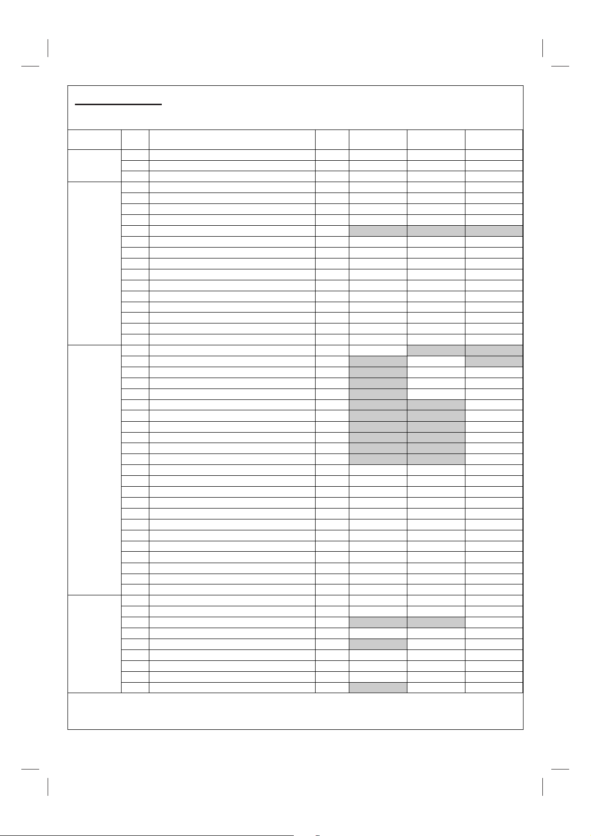
A. Parts List
Quantities vary according to model purchased. Specifications subject to change without prior notice. For more
details on hardware, please see the corresponding Hardware Reference Diagram for your barbecue model.
HOOD
BODY
TROLLEY
HARDWARE
CODEPART QTY
Hood (Pre-Assembled to Body)
A1
A2 Hood Handle 1
A3 Warming Rack 1
B1 Barbecue Body 1
B2 Burner 1
B3 Control Panel 1
B4 Knob 2
B5 Hose (if supplied)
B6 Lava Rock in Basket 1
B7 Cooking Grill 1
B8 Ignition Button 1
B9 Control Panel Heat Shield 1
B10 Main Electrode 1
B11 Hinge Bracket 2
B12 Body Heat Shield 1
B13 Body Support 2
B14 Grease Cup Holder 1
B15 Grease Cup 1
C1 Trolley Handle 1
C2 Side Shelf (with bracket)
C3 Side Shelf (without bracket)
C4 Side Shelf Bracket A
C5 Side Shelf Bracket B
C6 Side Burner Knob 1
C7 Side Burner Grid 1
C8 Side Burner Shelf 1
C9 Side Burner 1
C10 Side Burner Electrode 1
C11 Side Burner Valve / Hose Assembly 1
C12 Left Front Leg 1
C13 Left Rear Leg 1
C14 Right Front Leg 1
C15 Right Rear Leg 1
C16 Hose Tidy 1
C17 Gas Bottle Holder 1
C18 Leg End Loop 1
C19 Wheel Spacer 2
C20 Wheel 2
C21 Axle 1
C22 Bottom Shelf 1
C23 Gas Bottle Strap 1
D1 M6x15 Bolt
D2 M5x10 Bolt 4
D3 M4x10 Bolt 1
D4 ST4.0x10 Screw 3
D5 ST4.0x15 Screw 4
D6 ST4.8x15 Screw 2
D7 M8 Locknut 2
D8 M5 Nut 2
D9 Shelf Spacer
! Pre-Assembled Component
" Quantity varies according to model purchased
#$$Appearance, size, and construction may differ according to model
1
"
"
"
"
"
"
"
OUTBACK®
EXCEL 100T
!! !! !!
! ! !
! ! !
!! !! !!
! ! !
! ! !
!! !! !!
!! !! !!
! ! !
!! !! !!
!! !! !!
! ! !
!! !! !!
! ! !
! ! !
! ! !
! ! !
!
! ! !
! ! !
! ! !
! ! !
! ! !
! ! !
! ! !
! ! !
! ! !
! ! !
! ! !
!! !! !!
24 28 28
! ! !
! ! !
! !
! ! !
! ! !
! ! !
OUTBACK®
EXCEL 200T
1
1 1
1 1
1 1
8 4
OUTBACK®
EXCEL 300T
!
!
!
!
!
!
!
2
Page 3
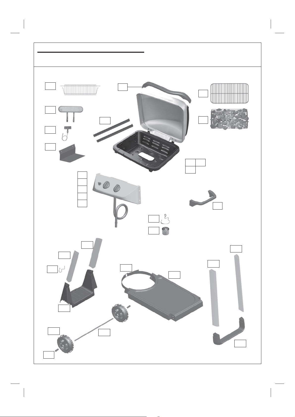
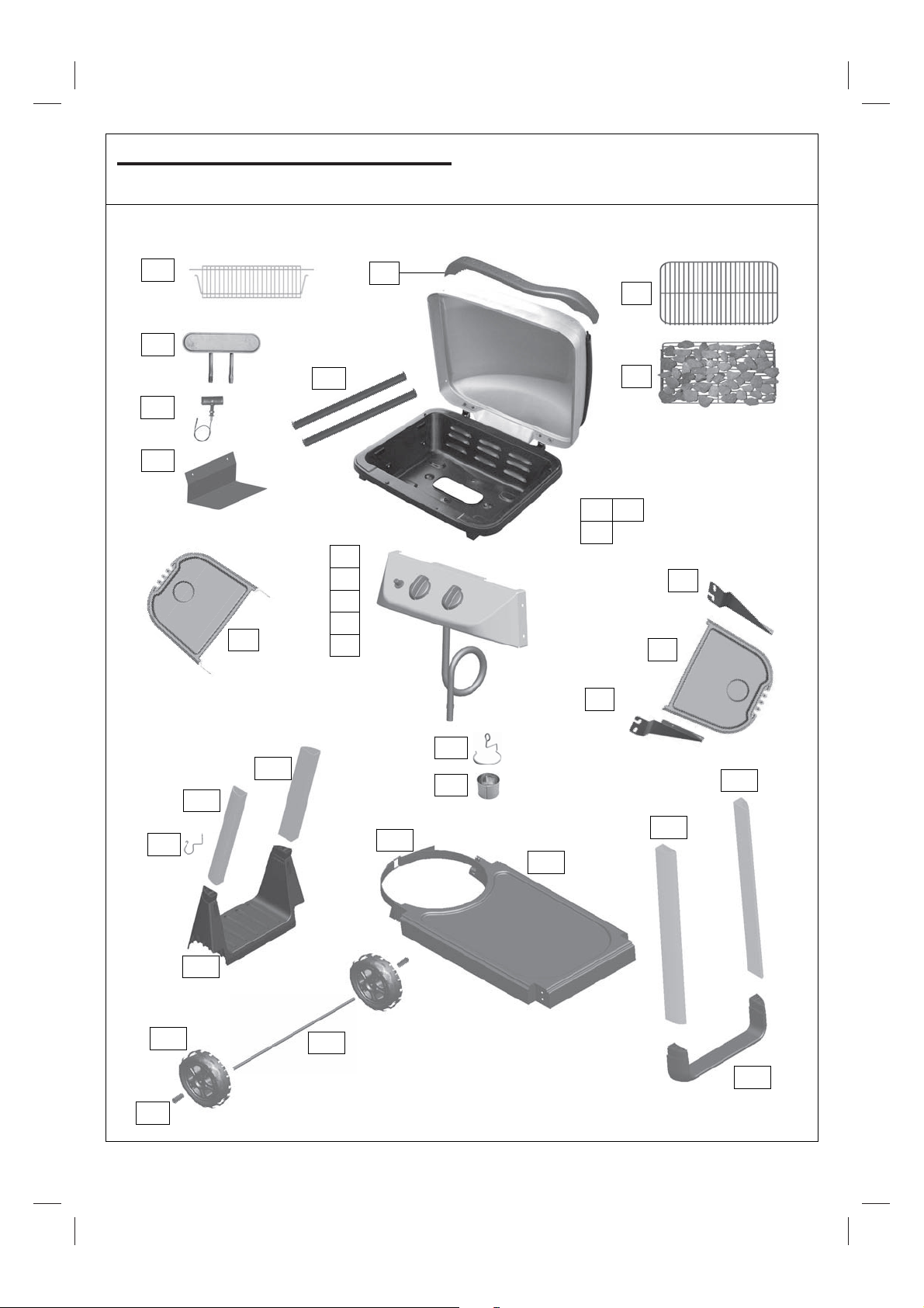
B1. Parts Diagram: Excel 100T
Quantities vary according to model purchased. Specifications subject to change without prior notice. For more
details on hardware, please see ‘Hardware Reference Diagram: Excel 100.’
B15
B14
A2
A3
B3
B4
B5
C1
B8
C13
C23
A1 B1
B11
Pre-assembled body unit
includes the following
individual parts:
B2
B12
B13
C16
C19
B9
C17
C20
C21
C18
C14
C15
C22
B7
B6
B10
C12
3
Page 4
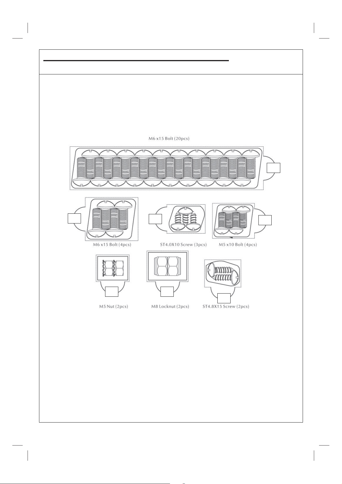
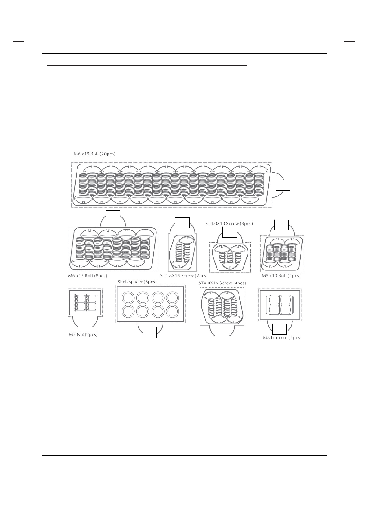
B2. Hardware Reference Diagram: Excel 100T
D1
D1
D4
D2
D6
D7 D8
Specifications subject to change without prior notice.
4
Page 5
C1. Parts Diagram: Excel 200T
Quantities vary according to model purchased. Specifications subject to change without prior notice. For more
details on hardware, please see ‘Hardware Reference Diagram: Excel 200.’
B15
B14
C3
A2
A3
A1 B1
B11
Pre-assembled body unit
includes the following
individual parts:
B2
B12
B13
B3
B4
B5
B8
B9
B7
B6
B10
C2
C4
C5
C13
C23
C16
C19
C17
C20
C21
C18
C14
C15
C22
C12
5
Page 6
C2. Hardware Reference Diagram: Excel 200T
D1
D2
D4
D8
D9
D7
D1
D5
D6
Specifications subject to change without prior notice.
6
Page 7
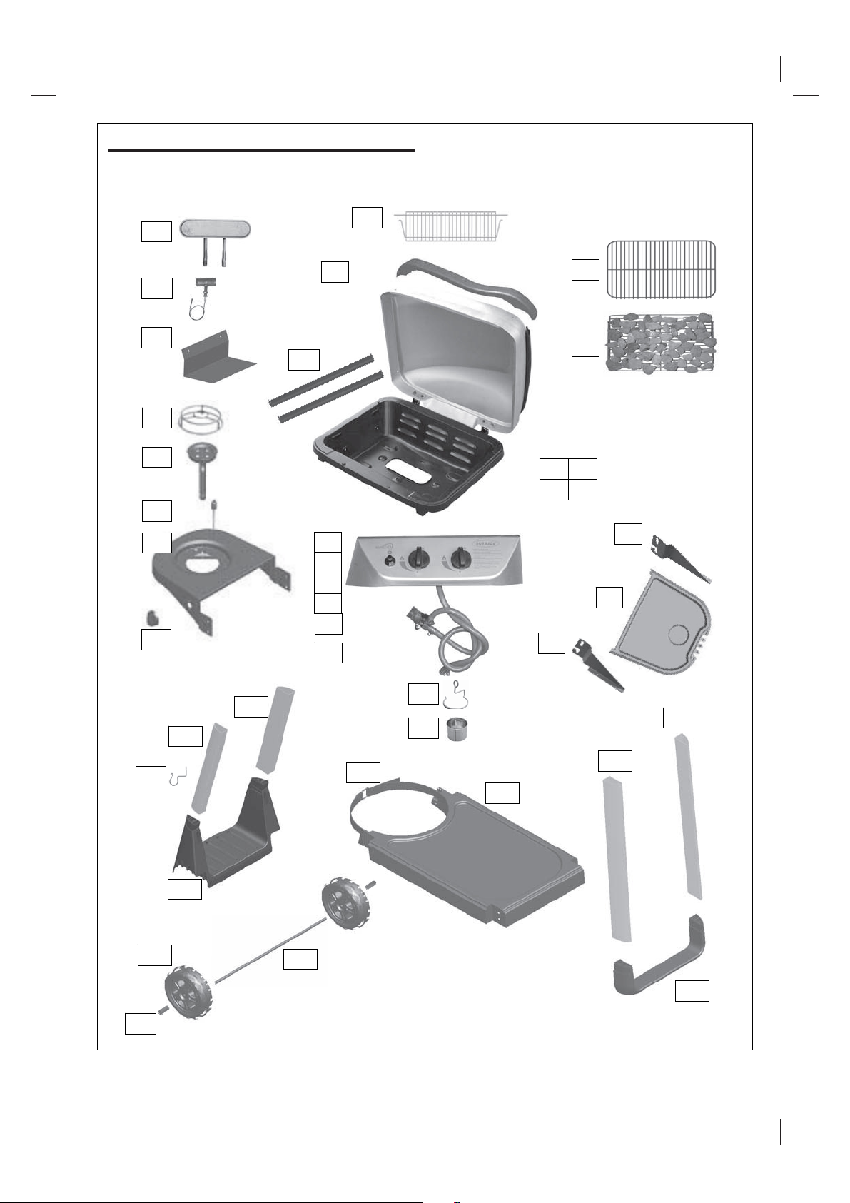
D1. Parts Diagram: Excel 300T
A2
A3
B3
B4
B5
B8
C7
C10
C9
C8
C6
A1 B1
B11
Pre-assembled body unit
includes the following
individual parts:
B2
B12
B13
B9
C11
B14
B15
B10
B7
B6
C3
C4
C5
C13
C23
C16
C19
C17
C20
C21
C18
C14
C15
C22
C12
Quantities vary according to model purchased. Specifications subject to change without prior notice. For more
details on hardware, please see ‘Hardware Reference Diagram: Excel 300.’
7
Page 8
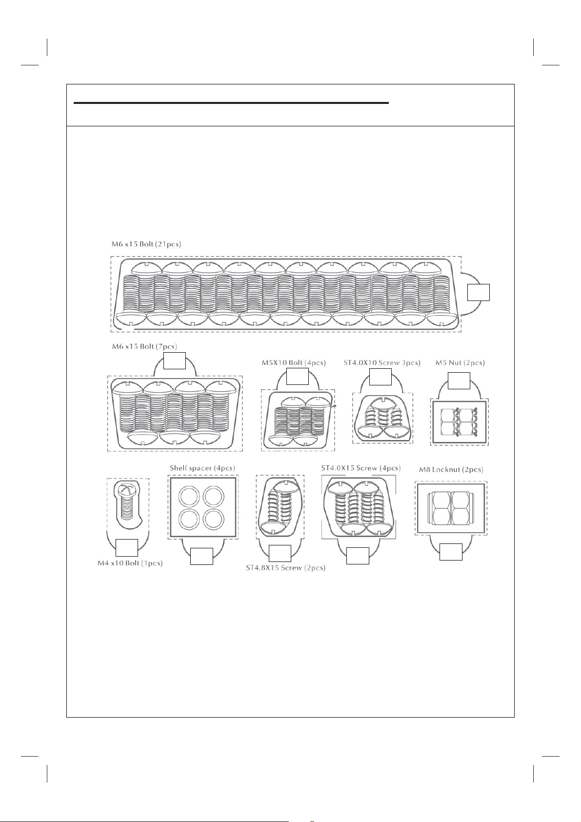
D2. Hardware Reference Diagram: Excel 300T
D1
D1
D2
D4
D8
D3
D9
D5
D6
D7
Specifications subject to change without prior notice.
8
Page 9
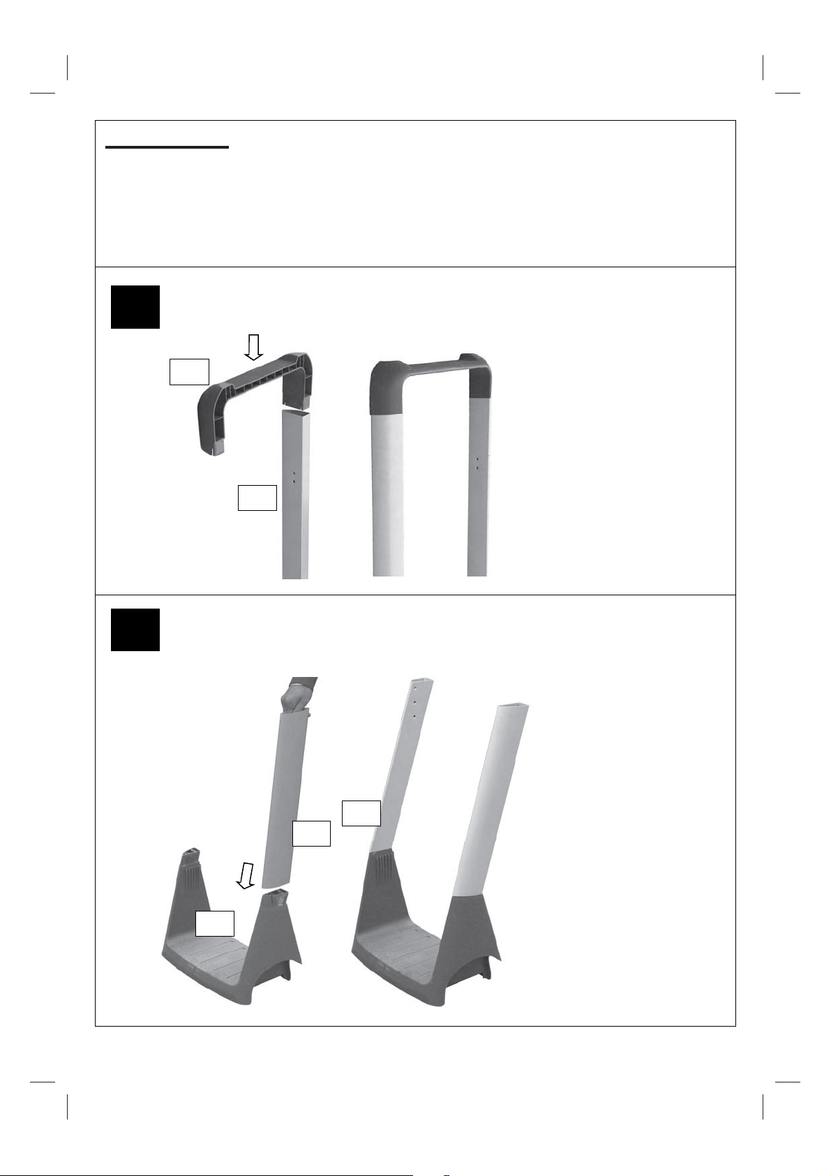
E. Assembly
C14
Attach the Left Front Leg
(C12) and Left Rear Leg
(C13) to the Gas Bottle
Holder (C17). The legs
are a push fit onto the gas
bottle holder. In case of
difficulty, they may need
tapping with a soft faced
mallet. Take care not to
damage the parts.
C18
Attach the Right Front Leg
(C14) and Right Rear Leg
(C15) to the Leg End Loop
(C18). The legs are a push
fit onto the leg end loop. In
case of difficulty, they may
need tapping with a soft
faced mallet. Take care not
to damage the parts.
C12
C13
C17
TOOLS NEEDED FOR ASSEMBLY:
Medium size flat blade or Philips/cross-point screwdriver, adjustable spanner or metric spanner set.
This barbecue requires two people for assembly. Please remove all packaging materials from all individual
parts before assembling. Please lay out all nuts and bolts and check lengths before assembling. Whilst
every care is taken during the manufacture of this product, care must be taken during the assembly in case
sharp edges are present.
% Excel 100T %$Excel 200T %$Excel 300T$
1
% Excel 100T %$Excel 200T %$Excel 300T$
2
9
Page 10

Attach the Bottom Shelf (C22) to the Gas Bottle
Holder (C17) using ST4.8x15 Screws (D6).
Take care not to over tighten these screws
which will damage the plastic gas bottle holder.
Attach the leg assembly to the bottom
shelf assembly using M6x15 Bolts (D1).
4
3
% Excel 100T %$Excel 200T %$Excel 300T$
% Excel 100T %$Excel 200T %$Excel 300T$
C22
C17
D6
D1
10
Page 11

Slide the Wheels (C20) over
each end of the axle. Secure
the wheels into place with the
M8 Locknuts (D7).
Insert the Axle (C21) through the clamping brackets underneath the
Gas Bottle Holder (C17) and tighten the clamping screws.Take care
not to over tighten these screws which will damage the plastic gas
bottle holder.
Slide a W heel Spacer (C19) over each end of the Axle (C21).Note:
the spacers are packed in a plastic bag with the main electrode,
grease cup holder and grease cup.
Attach the Body Support (B13) to the legs
using M6x15 Bolts (D1).
Note: The notches on these supports
should be on the outside in order to attach
the body more easily.
Carefully turn the completed trolley over, right
side up.
6
5
% Excel 100T %$Excel 200T %$Excel 300T$
% Excel 100T %$Excel 200T %$Excel 300T$
C17
C21
C19
C20
D7
D1
B13
11
Page 12

Attach the Hood Handle (A2) to the Hood (A1) using
the M5x10 Bolts (D2).
Carefully place the Barbecue Body (B1) onto the
tops of the legs.
Attach the barbecue body to the trolley assembly
using the M6x15 Bolts (D1). Ensure the tabs on
the body fit over the legs as shown in the diagram
and do not go down inside of the legs.
8
7
% Excel 100T %$Excel 200T %$Excel 300T$
% Excel 100T %$Excel 200T %$Excel 300T$
A2
A1
D2
B1
D1
12
Page 13

Feed the Grease Cup Holder (B14)
through the hole in barbecue body.
Insert the Grease Cup (B15) into the grease
cup holder.
Attach the Control Panel (B3) assembly to the trolley assembly using the M6x15 Bolts
(D1).
10
9
% Excel 100T %$Excel 200T %$Excel 300T$
% Excel 100T %$Excel 200T %$Excel 300T$
B14
B15
13
Page 14

Insert the Main Electrode (B10) into the hole at the bottom of the barbecue body and
secure with the pre-assembled nut.
Feed the Burner (B2) into barbecue body.
Ensure that the burner venturi tubes are over
the ends of the gas valves. They are a loose fit
and not a gas tight seal. Secure the burner
with the ST4.0x10 Screws (D4).
View from underneath the body.
12
11
% Excel 100T %$Excel 200T %$Excel 300T$
% Excel 100T %$Excel 200T %$Excel 300T$
D4
B2
14
Page 15

Attach the Body Heat Shield (B12) to barbecue body
using the M5x10 Bolts (D2) and M5 Nuts (D8).
Carefully lay the Lava Rock (B6) into the
barbecue body ensuring it lies level within the
body. Lay the Cooking Grill (B7) into place.
Attach the Warming Rack (A3), to the hood
and barbecue body as shown. Make sure that
the swing legs fix to the body of the barbecue
and the shorter, fixed legs go through the
holes in the hood.
14
13
% Excel 100T %$Excel 200T %$Excel 300T$
% Excel 100T %$Excel 200T %$Excel 300T$
B12
B6
B7
A3
15
Page 16

Attach the Trolley Handle (C1) to the right
front and right rear legs using the M6x15
Bolts (D1).
Excel 200T and 300T users, skip this step and proceed directly to step 16.
Excel 100T users, skip this step and proceed directly to step 24.
16
15
% Excel 100T &$Excel 200T &$Excel 300T$
& Excel 100T %$Excel 200T %$Excel 300T$
C1
D1
Attach the Side Shelf Bracket A (C4) and Side Shelf Bracket B (C5) to the Side Shelf (C3) using
ST4.0x15 Screws (D5).
C4
C5
C3
16
Page 17

17
Attach the Side Shelf (C2) to the left hand side of the barbecue by sliding a Shelf Spacer (D9) onto a
M6x15 Bolt (D1) and fitting the shelf to the lower fixing point on the rear leg as shown. Repeat for the
front leg. Slide a Shelf Spacer (D9) onto a M6x15 Bolt (D1) and screw it into the upper fixing point on
the rear legs as shown. Repeat for the front leg.
Hook the shelf onto the upper pins to extend it to its normal horizontal position.
C2
D1
D9
Attach the assembled Side Shelf (C3) to the right hand side of the barbecue by sliding a Shelf Spacer
(D9) onto a M6x15 Bolt (D1) and fitting the shelf to the lower fixing point on the rear leg as shown.
Repeat for the front leg. Slide a Shelf Spacer (D9) onto a M6x15 Bolt (D1) and screw it into the upper
fixing point on the rear legs as shown. Repeat for the front leg.
Hook the shelf onto the upper pins to extend it to its normal horizontal position.
C3
D1
D9
Excel 300T users, skip this step and proceed directly to step 19.
C4
C5
& Excel 100T %$Excel 200T %$Excel 300T$
18
& Excel 100T %$Excel 200T &$Excel 300T$
17
Page 18

Attach the Side Burner Shelf (C8) to the left front and left rear legs using M6x15 Bolts (D1).
Remove the screws from Side Burner
Valve / Hose Assembly (C11) and
secure it to the side shelf with those 2
screws.
Assemble the Side Burner Knob (C6)
onto the side burner valve.
Excel 200T users, skip this step and proceed directly to step 24.
20
19
& Excel 100T &$Excel 200T %$Excel 300T$
& Excel 100T &$Excel 200T %$Excel 300T$
C8
D1
C6
C11
18
Page 19

Place the Side Burner Electrode (C10) onto the
side burner shelf as shown. Place the Side
Burner (C9) through the central hole. Fit the
side burner venturi tube over the gas valve
outlet. This is a loose fit and not a gas tight
seal. Secure the electrode and burner with
M4x10 Bolt (D3).
Rotate the hose anti-clockwise
so that it touches the leg of the
barbecue.
Re-tighten the hose clip to secure
the hose in place, making sure
that the hose touches the leg of
the barbecue, but not the body or
heat shield.
Important: Regularly check the hose positioning to ensure that it is not in contact with any hot
surfaces, such as the bottom of the body or the heat shield.
Once the hose is connected, check to ensure that it is not in contact with the barbecue body or Body
Heat Shield (B12).
22
21
& Excel 100T &$Excel 200T %$Excel 300T$
& Excel 100T &$Excel 200T %$Excel 300T$
B12
C10
C9
D3
Loosen off the hose clip which
connects the hose to the side
burner gas valve.
19
Page 20

Connect the electrode
wire to the Ignition
Button (B8) under the
control panel.
Side burner electrode
wire goes here.
Main burner
electrode wire
goes here.
Place the Side Burner Grid (C7) onto
the side burner shelf.
Fix the Hose Tidy (C16) onto the short leg front using a ST4.0x10 Screw (D4), then clip the hose (if
supplied) into hose tidy as shown.
Note: there are two fixing holes for the hose tidy:
Excel 100T and Excel 200T Users: please fix the hose tidy to the lower hole on the short leg front.
Excel 300T Users: please fix the hose tidy to the upper hole on the short leg front.
24
23
& Excel 100T &$Excel 200T %$Excel 300T$
% Excel 100T %$Excel 200T %$Excel 300T$
Note: Do not use any cooking utensils (pots,
pans etc.) with a diameter of over 280mm on
the side burner. Always keep the utensils in
the centre of the side burner.
B8
C7
C16
20
Page 21

F. Important Information
Please read these instructions carefully
before assembly and use.
!" Retain these instructions for future reference.
!" For outdoors use only – do not use indoors.
Do not use below ground level.
!" For use with LPG bottled gas only. A fixed
pressure regulator of 28-30mbar must be
used for butane or 37mbar for propane.
!" Remove lava rock from plastic shrink pack
before lighting.
!" Do not use within 1m of any flammable
structure or surface.
!" LP gas cylinders should not be placed
directly underneath the barbecue.
!" LP gas cylinders must not be stored or used
in the horizontal position. A leak would be
very serious and liquid could enter the gas
line.
!" When igniting barbecue open its hood before
lighting.
!" Do not move the barbecue while alight.
!" This barbecue must not be left unattended
when lit.
!" The hood handle can become very hot. Grip
only the centre of the handle. Use of a
cooking glove is advised.
!" Use caution when opening the hood, as hot
steam inside is released upon opening.
!" Parts of this barbecue become very hot –
care must be taken when children, elderly
people, and animals are present.
!" Always turn off the gas bottle when the
barbecue is not in use.
!" Never cover a barbecue until it has
completely cooled.
!" Never use the barbecue with the side shelf in
the down position.
!" Leak test annually, and whenever the gas
bottle is removed or replaced.
!" Do not store flammable materials near this
barbecue.
!" Do not use aerosols near this barbecue.
!" Failure to follow the manual’s instructions
could result in serious injury or damage.
!" If you have any queries regarding these
instructions, contact your local dealer.
G. Gas and Regulator
This barbecue can use either propane or butane
LPG bottled gas. Propane bottles, normally red
coloured, will supply gas all year round, even on
cold winter days. A spanner may be required to
change gas bottles. Butane bottles, normally
blue, will supply sufficient gas in summer, but
performance of the barbecue may be affected
once the gas temperature starts to fall below
+10°C. The bottle should never
trolley base and placed directly under the
barbecue. Gas bottles should never be stored or
used laid on their side. Never store gas bottles
indoors.
For optimal performance, we suggest the
following:
Model Butane Minimum
Outback®
Excel 100T
Outback®
Excel 200T
Outback®
Excel 300T
Bottle Size
6kg 3.9kg
6kg 3.9kg
15kg 6kg
be stood on the
Propane Minimum
Bottle Size
Suitable regulators for butane must have an
outlet pressure of 28-30mbar. For propane, the
regulator must have an outlet pressure of
37mbar. YOU MUST HAVE THE PROPER
REGULATOR AND BOTTLE IN ORDER FOR
THE BARBECUE TO OPERATE SAFELY AND
EFFICIENTLY. USE OF AN INCORRECT OR
FAULTY REGULATOR IS DANGEROUS AND
WILL INVALIDATE ANY WARRANTY. Please
consult your local gas dealer for the most
suitable gas bottles and regulators.
H. Installation
H1. Selecting a Location
This barbecue is for outdoor use only and should
be placed in a well-ventilated area. Take care to
ensure that it is not placed UNDER any
combustible surface. The sides of the barbecue
should NEVER be closer than 1 metre from any
combustible surface. Keep this barbecue away
from any flammable materials!
H2. Precautions
Do not obstruct any ventilation openings in the
barbecue body. Secure the gas bottle on the
cylinder holder and always tighten it with the
black strap provided. Should you need to change
the gas bottle, confirm that the barbecue is
switched off, and that there are no sources of
ignition (cigarettes, open flame, sparks, etc.)
near before proceeding. Inspect the hose for
damage and ensure it is securely attached with
21
Page 22

worm drive clips or swaged fittings. Ensure no
part of the flexible hose is touching any hot
barbecue parts. If the hose is damaged, it must
be replaced with hose suitable for use with LPG
and meet the national standards for the country
of use. The length of hose shall not exceed
1.5m. N.B. – The date on UK hose is the date of
manufacture, not the expiry date.
H3. Fixing the Regulator to the Gas Bottle
Confirm all barbecue control knobs are in the off
position. Connect the regulator to the gas bottle
according to your regulator and bottle dealer’s
instructions.
H4. Leak Testing (To be performed in a wellventilated area.)
Confirm all control knobs are in the off position.
Open the gas control valve on the bottle or
regulator. Check for leaks by brushing a solution
of ½ water and ½ soap over all gas system
joints, including all valve connections, hose
connections and regulator connections. NEVER
USE AN OPEN FLAME to test for leaks at
anytime. If bubbles form over any of the joints,
there is a leak. Turn off the gas supply and
retighten all joints. Repeat test. If bubbles form
again, do not use the barbecue. Please contact
your local dealer for assistance. Leak test your
barbecue annually. Check the hose connections
are tight and leak test them each time you
reconnect the gas bottle.
I. Operation
I1. Warning
!" Before proceeding, make certain that you
understand the IMPORTANT
INFORMATION section of this manual.
I2. Preparation Before Cooking
To prevent foods from sticking to the cooking
grill, please use a long handled brush to apply a
light coat of cooking or vegetable oil before each
barbecuing session. (Note: When cooking for
the first time, paint colours may change
slightly as a result. This is normal and
should be expected.)
I3. Lighting the Barbecue
!" Open the barbecue hood.
!" Ensure all knobs are in the off position.
Open the gas control valve on the gas
bottle or regulator.
!" Push and turn the leftmost control knob to
the high position. Press the ignition button
rapidly several times until left portion of the
burner is lit. If burner fails to ignite, turn
control knob to the off position and turn gas
off at the bottle or regulator. Wait five
minutes, then repeat the above steps. After
successful lighting of the left side, ignite the
remaining portion of the burner. If the
burner fails to ignite after following above
procedure, turn all the knobs to the off
position. Close the gas valve on the gas
bottle. Wait 5 minutes, then repeat the
above steps. If the barbecue still fails to
light, please refer to the manual ignition
instructions in section below.
!" After ignition, the burner should be burned
at the high position for 3-5 minutes in order
to preheat the barbecue. This process
should be done before every cooking
session. The hood should be open during
preheating.
!" After completion of preheating, the burner
should normally be turned down to a lower
position for best cooking results.
I4. Manual Lighting Instructions
!" Open the barbecue hood.
!" Ensure all knobs are in the off position.
Open the gas control valve on the gas
bottle or regulator.
!" Insert lit match through the match-lighting
hole underneath the barbecue.
!" Push and turn the rightmost control knob
anti-clockwise to the high position.
!" After the right portion of the burner is lit,
light the remaining portion of the burner.
!" If burner fails to ignite, contact your local
dealer for assistance.
!" After ignition, the burner should be burned
at the high position for 3-5 minutes in order
to preheat the barbecue. This process
should be done before every cooking
session. The hood should be open during
preheating.
!" After completion of preheating, the burner
should normally be turned down to a lower
position for best cooking results.
I5. Warming Rack
Warming racks are a convenient way to keep
cooked food warm or to warm items such as
bread rolls. Care should be taken to ensure that
any items placed on the warming rack are
cooked through and do not continue to cook and
drip fat or meat juices, which could drip onto the
hood and down the back of the barbecue.
I6. Grill Cooking
The burner heats up the lava rock underneath
the grill, which in turn heats the food on the grill.
The natural food juices produced during cooking
22
Page 23

fall onto the hot lava rock below and vaporise.
The subsequent rising smoke bastes the food,
as it travels upwards, imparting that unique
barbecued flavour.
When using your barbecue for grill cooking, you
may wish to place the hood in the closed
position which will hold the heat in and give
more even cooking of the food. This should only
be done with the burner turned down to a lower
setting.
I7. Roasting Hood Cooking
Barbecues equipped with a roasting hood give
the option of cooking with hood closed to form
an ‘oven’ for roasting food, such as joints of
meat, whole chickens, etc.
When roasting, turn the burner under the food to
the OFF position. Close the hood and turn the
other burner down to a lower setting i.e. low to
medium to achieve the temperature required.
DO NOT ALLOW YOUR BARBECUE TO
OVERHEAT. Avoid lifting the hood
unnecessarily as heat is lost each time the hood
is opened.
I8. Side-Burner Cooking
When using the side-burner, care should be
taken to ensure that pans are central and flat on
the side-burner grid.
I9. Flare-Up Control
Flare-ups occur when meat is barbecued, and
its fat and juices fall upon the hot lava rock.
Smoke helps give food its barbecued flavour,
but avoid excessive flare-up to prevent food
being burned. To control flare-up, it is advisable
to trim away excess fat from meat and poultry
before grilling. The burner should be turned
down to a lower setting to reduce flare-up.
Flare-ups can be extinguished by applying
baking soda or salt directly onto the lava rocks.
Always protect your hands when handling
anything near the cooking surface of the
barbecue.
I10. End of Cooking Session
After each cooking session, turn the barbecue
burner to the “high” position and burn for 5
minutes. This procedure will burn off cooking
residue, thus making cleaning easier. Make sure
the hood is open during this process.
I11. Turning Off Your Barbecue
When you have finished using your barbecue,
turn all the control valves fully clockwise to the
“Off” position, then switch off the gas at the
bottle. Wait until the barbecue is sufficiently cool
before closing its hood.
J. Care And Maintenance
Regularly clean your barbecue between uses
and especially after extended periods of
storage. Ensure the barbecue and its
components are sufficiently cool before
cleaning. Do not leave the barbecue exposed to
outside weather conditions or stored in damp,
moist areas.
!" Never douse the barbecue with water when
its surfaces are hot.
!" Never handle hot parts with unprotected
hands.
In order to extend the life and maintain the
condition of your barbecue, we strongly
recommend that the unit be covered when left
outside for any length of time, especially during
the winter months. Heavy-duty Outback®
barbecue covers and other accessories are
available from you local Outback® stockist.
Even when your barbecue is covered for its
protection, it must be inspected on a regular
basis as damp or condensation can form which
may result in damage to the barbecue. Any rust
that is found that does not come into contact
with the food should be treated with a rust
inhibitor and painted with barbecue paint or a
heat resistant paint. Chrome plated warming
racks should be coated with cooking oil.
J1. Cooking Grill
Clean with hot soapy water. To remove any food
residue, use a mild cream cleaner on a nonabrasive pad. Rinse well and dry thoroughly.
J2. Burner Maintenance
Your burner has been preset for optimal flame
performance. You will normally see a blue
flame, possibly with a small yellow tip when the
burner is alight. If the flame pattern is
significantly yellow, this could be a problem
caused by grease from cooking blocking the
burner or spiders or other insects in the burner
venturi. This can result in the flow of the gas and
air mixture being restricted or blocked which
may result in a fire behind the control panel
causing serious damage to your barbecue. If
this happens, the gas should be immediately
turned off at the bottle. Burners should be
inspected and cleaned on a regular basis in
addition to the following conditions:
1) Bringing the barbecue out of storage.
2) One or more of the burners do not ignite.
23
Page 24

3) The burner flame pattern is significantly
Venturi tube
yellow.
4) The gas ignites behind the control panel.
To clean a burner, remove it from the barbecue
by removing the 2 securing screws underneath
the body of the barbecue. The outside of the
burner can be cleaned with a wire brush.
Clean the portholes with a pipe cleaner or piece
of wire. Take care not to enlarge the portholes.
Clean the insect screen on the end of the venturi
tube with a bristle brush (i.e. an old toothbrush).
Clean the venturi tube with a pipe cleaner or
piece of wire. You may need a torch to see into
the venturi tube to make sure it is clear. ”Turn
the burner up on end and lightly tap against a
piece of wood to dislodge any debris from
inside.”
J3. Lava Rock
It is not necessary to remove and wash the lava
rock in order to keep it clean. Burning off the
residue after each cooking should be sufficient.
Heavily impregnated lava rock should be turned
over so that the dirty side faces the burners in
order to burn off any residue. Replacement lava
rock is available from your local Outback®
stockist.
J4. Barbecue Body
Regularly remove excess grease or fat from the
barbecue body with a soft plastic or wooden
scraper. It is not necessary to remove all the
grease from the body. If you need to clean fully,
use hot soapy water and a cloth, or nylonbristled brush only. Remove cooking surfaces
and burners before full cleaning. Do not
immerse the gas controls or manifold in water.
Check burner operation after carefully refitting
into body. Check the grease cup and clean out
any grease that has drained into it.
J5. Fixings
All screws and bolts, etc. should be checked
and tightened on a regular basis.
J6. LPG Hose
The LPG hose does not have a time-limited in-
service life but it is essential that the hose and
end connections are regularly inspected and
replaced if showing signs of:
!" Physical damage such as – cuts or abrasion,
cracking, stretching, flattening or kinking;
!" Environmental deterioration such as –
stiffening, cracking, de-lamination of outer
covering, chemical degradation i.e. softening
of outer coating by contact with oil;
!" Hose service failure such as – blistering, soft
spots, rupture or corrosion or loosening of
the swaged fittings or worm drive clips
attaching the hose.
J7. Fixings
All screws and bolts, etc. should be checked
and tightened on a regular basis.
J8. Storage
Store your barbecue in a cool dry place. It must
be inspected on a regular basis as damp or
condensation can form which may result in
damage to the barbecue. It may be necessary to
dry the barbecue and the inside of the cover if
used. Mould can grow under these conditions
and should be cleaned and treated if required.
Any rust that is found that does not come into
contact with the food should be treated with a
rust inhibitor and painted with barbecue paint or
a heat resistant paint. Chrome plated warming
racks and grills should be coated with cooking
oil. Wrap the burners in aluminium foil to help
prevent insects or other debris from obstructing
the burners.
The gas bottle must be always be disconnected
from the barbecue and stored in a well
ventilated area at least 1 metre away from any
fixed ignition source. Do not store inside
residential accommodation. Never store
cylinders below ground level (e.g. cellars). Do
not let children tamper with bottles.
24
Page 25

K. Technical Specifications
CE
Heat
Outback®
Excel
100T
Outback®
Excel
200T
Outback®
Excel
300T
Side
Burner
Approval
0359
359BS791
0359
359BS791
0359
359BS791
359
359BS791
Input
6.2
kW
6.2k
W
6.2k
W
2.3k
W
Burners
Gas Consumption:
Excel 100T: 446g/hr
Excel 200T: 446g/hr
Excel 300T: 446g/hr
Side Burner: 165g/hr
Countries of Use:
BE, CH, CY, CZ, ES, FR, GB, GR, IE, IT, LT, LU, LV, PT,
I
3+(28-30/37)
I
RO, HR, TR, BG, IS, LU, MT
I
I
SK, SI
BE, CY, DK, EE, FI, FR, HU, IT, LT, NL, NO, SE, SI, SK,
3B/P(30)
PL
3B/P(37)
AT, DE, SK, CH
3B/P(50)
Specifications are subject to change without prior
notice.
Injector
Size
0.89mm
0.89mm
0.84mm
0.79mm
0.89mm
0.89mm
0.84mm
0.79mm
0.89mm
0.89mm
0.84mm
0.79mm
0.74mm
0.74mm
0.71mm
0.69mm
LPG mixture: 30 mbar
LPG mixture: 37 mbar
LPG mixture: 50 mbar
LPG mixture: 30 mbar
LPG mixture: 37 mbar
LPG mixture: 50 mbar
LPG mixture: 30 mbar
LPG mixture: 37 mbar
LPG mixture: 50 mbar
LPG mixture: 30 mbar
LPG mixture: 37 mbar
LPG mixture: 50 mbar
1
1
1
1
Gas /Pressure
Butane: 28-30 mbar
Propane: 37 mbar
Butane: 28-30 mbar
Propane: 37 mbar
Butane: 28-30 mbar
Propane: 37 mbar
Butane: 28-30 mbar
Propane: 37 mbar
NOTE:
25
Page 26

L. Troubleshooting
Problem Possible Cause Solution
Burners will not light using
the ignition system
Burner will not light with a
match
Low flame or flashback
(fire in burner tube— a
hissing or roaring noise
may be heard)
Gas valve knob difficult to
turn
LP gas bottle is empty Replace with full bottle
Faulty regulator Have regulator checked or replaced
Obstructions in burners Clean burners
Obstructions in gas jets or gas hose Clean jets and gas hose
Electrode wire is loose or disconnected
on electrode or ignition unit
Electrode or wire is damaged Change electrode and wire
Faulty pushbutton ignitor Change ignitor
LP gas bottle is empty Replace with full bottle
Faulty regulator Have regulator checked or replaced
Obstructions in burners Clean burners
Obstructions in gas jets or gas hose Clean jets and gas hose
LP gas bottle too small Use larger bottle
Obstructions in burners Clean burners
Obstructions in gas jets or gas hose Clean jets and gas hose
Windy conditions Use BBQ in a more sheltered position
Gas valve jammed Replace gas valve
Reconnect wire
For reference and correspondence,
record your serial number here.
(See sticker on side of barbecue body.)
Serial No.__________________
This number may be required when
ordering spare parts or accessories. A
part reference number may also be
required where applicable.
26
Page 27

OUTBACK UK LTD
WARRANTY
OUTBACK barbecues are warranted to the original purchaser against defects in materials and
workmanship for a period of one (1) year from the date of purchase. OUTBACK UK will, within
this period, supply replacements for defective parts free of charge provided that:
#" The product has not been used for trade, professional or hire purposes.
#" The product has not been subjected to misuse or neglect, including fat fires and flare ups
or use of a faulty or incorrect regulator.
#" The product has not sustained damage through foreign objects, substances or accidents.
#" The care and maintenance instructions given in your Outback manual have been followed.
This warranty is offered as an extra benefit and is in addition to the customers’ statutory rights.
Outback UK does not warranty in any way the gas cylinder.
If you have any queries regarding the assembly or use of your barbecue please contact
Outback UK
In the unlikely event that you experience
problems with this barbeque, please contact:
website: www.outbackbarbecues.com
27
 Loading...