

Ouster OS-1-16, OS-1-64 Owner's Manual
Software User Guide
Release v1.12.0
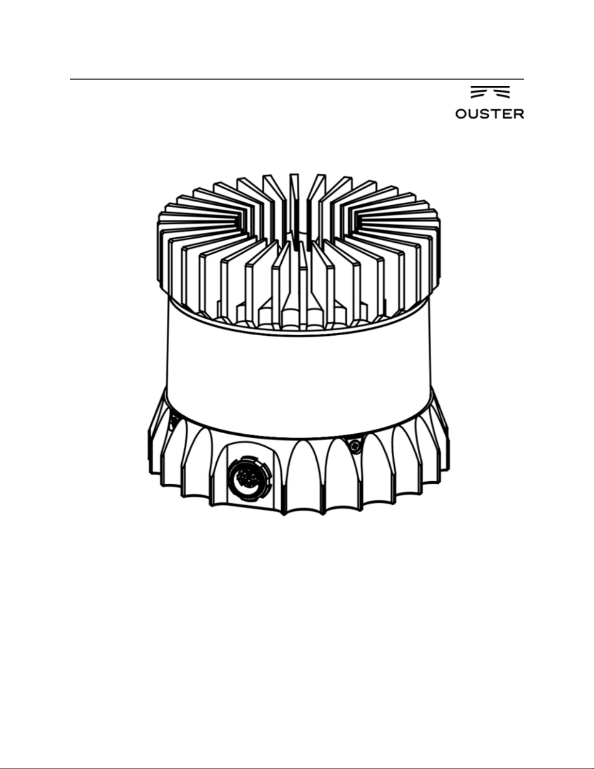
OS-1-64/16 High Resolution Imaging Lidar

May 02, 2019
Software User Guide
1 Introduction 5
2 Safety & Legal Notices 5
3 Drivers & Interface 6
3.1 Network Configuration . . . . . . . . . . . . . . . . . . . . . . . . . . . . . . . . . . . . . . . . . . 6
3.2 HTTP Interface . . . . . . . . . . . . . . . . . . . . . . . . . . . . . . . . . . . . . . . . . . . . . . 7
3.3 TCP API Command Set . . . . . . . . . . . . . . . . . . . . . . . . . . . . . . . . . . . . . . . . . . 10
3.4 Lidar Data Format . . . . . . . . . . . . . . . . . . . . . . . . . . . . . . . . . . . . . . . . . . . . . 18
3.5 IMU Data Format . . . . . . . . . . . . . . . . . . . . . . . . . . . . . . . . . . . . . . . . . . . . . 19
3.6 Data Rates . . . . . . . . . . . . . . . . . . . . . . . . . . . . . . . . . . . . . . . . . . . . . . . . . 19
4 Coordinate Frames 19
4.1 Sensor Coordinate Frame . . . . . . . . . . . . . . . . . . . . . . . . . . . . . . . . . . . . . . . . . 19
4.2 Lidar Intrinsic Beam Angles . . . . . . . . . . . . . . . . . . . . . . . . . . . . . . . . . . . . . . . 20
4.3 Lidar Range Data To XYZ Lidar Coordinate Frame . . . . . . . . . . . . . . . . . . . . . . . . . . . 20
4.4 Lidar Range Data To Sensor XYZ Coordinate Frame . . . . . . . . . . . . . . . . . . . . . . . . . . 21
4.5 IMU Data To Sensor XYZ Coordinate Frame . . . . . . . . . . . . . . . . . . . . . . . . . . . . . . 21
5 Time Synchronization 22
5.1 Timing Overview Diagram . . . . . . . . . . . . . . . . . . . . . . . . . . . . . . . . . . . . . . . . 22
5.2 Sensor Time Source . . . . . . . . . . . . . . . . . . . . . . . . . . . . . . . . . . . . . . . . . . . . 22
5.3 External Trigger Clock Source . . . . . . . . . . . . . . . . . . . . . . . . . . . . . . . . . . . . . . 23
5.4 NMEA Message Format . . . . . . . . . . . . . . . . . . . . . . . . . . . . . . . . . . . . . . . . . 25
6 Updating Firmware 26
7 Troubleshooting 27
8 HTTP API Reference 28
8.1 system/firmware . . . . . . . . . . . . . . . . . . . . . . . . . . . . . . . . . . . . . . . . . . 28
8.2 system/network . . . . . . . . . . . . . . . . . . . . . . . . . . . . . . . . . . . . . . . . . . . 28
8.3 system/time . . . . . . . . . . . . . . . . . . . . . . . . . . . . . . . . . . . . . . . . . . . . . . 31
9 PTP Quickstart Guide 38
9.1 Assumptions . . . . . . . . . . . . . . . . . . . . . . . . . . . . . . . . . . . . . . . . . . . . . . . 38
9.2 Physical Network Setup . . . . . . . . . . . . . . . . . . . . . . . . . . . . . . . . . . . . . . . . . . 38
9.3 Third Party Grandmaster Clock . . . . . . . . . . . . . . . . . . . . . . . . . . . . . . . . . . . . . . 39
9.4 Linux PTP Grandmaster Clock . . . . . . . . . . . . . . . . . . . . . . . . . . . . . . . . . . . . . . 39
9.5 Verifying Operation . . . . . . . . . . . . . . . . . . . . . . . . . . . . . . . . . . . . . . . . . . . . 46
9.6 Tested Grandmaster Clocks . . . . . . . . . . . . . . . . . . . . . . . . . . . . . . . . . . . . . . . . 47
HTTP Routing Table 48
2

Change Log
Version v1.6.0
Date 2018-08-16
Desciption Add: get_sensor_info command gives prod_line info.
Version v1.7.0
Date 2018-09-05
Desciption No TCP command change.
Version v1.8.0
Date 2018-10-11
Desciption Add: get_sensor_info command gives INITIALIZING, UPDATING, RUNNING,
ERROR and UNCONFIGURED status.
Version v1.9.0
Date 2018-10-24
Desciption No TCP command change.
Version v1.10.0
Date 2018-12-11
Desciption Remove all references of “pulse_mode”.
Add “get_alerts”, “pps_rate” and “pps_angle” usage commands and expected output.
Remove TCP commands prior to v1.5.1.
Version v1.11.0
Date 2019-03-25
Desciption Add section on HTTP API commands.
TCP Port now hardcoded to 7501; port is no longer configurable.
Update to SYNC_PULSE_IN AND MULTIPURPOSE_IO interface and configuration parameters
(see details below).
3

Details on interface changes:
Configuration parameters name changes:
• “pps_in_polarity” changed to “sync_pulse_in_polarity”
• “pps_out_mode” changed to “multipurpose_io_mode”
• “pps_out_polarity” changed to “sync_pulse_out_polarity”
• “pps_rate” changed to “sync_pulse_out_frequency”
• “pps_angle” changed to “sync_pulse_out_angle”
• “pps_pulse_width” changed to “sync_pulse_out_pulse_width”
New configuration parameters:
• “nmea_in_polarity”
• “nmea_ignore_valid_char”
• “nmea_baud_rate”
• “nmea_leap_seconds”
Configuration parameters option changes:
• timestamp_mode
– “TIME_FROM_PPS” changed to “TIME_FROM_SYNC_PULSE_IN”
• multipurpose_io_mode (formerly pps_out_mode)
– “OUTPUT_PPS_OFF” changed to “OFF”
– “OUTPUT_FROM_PPS_IN_SYNCED” changed to “OUT-
PUT_FROM_SYNC_PULSE_IN”
– Removed “OUTPUT_FROM_PPS_DEFINED_RATE”
– Added “INPUT_NMEA_UART”
TCP command changes:
• Added commands:
– “get_time_info”
• Changed commands:
– “get_config_txt” (returned dictionary keys match parameter changes)
• Removed commands:
– “set_pps_in_polarity”
– “get_pps_out_mode”
– “set_pps_out_mode”
– “get_timestamp_mode”
– “set_timestamp_mode”
Polarity changes:
• “sync_pulse_in_polarity” was corrected to match parameter naming.
• “sync_pulse_out_polarity” was corrected to match parameter naming.
Version v1.12.0
Date
Desciption Corrected IMU axis directions to match sensor coordinate frame. See section Section 4.1 for
details on sensor coordinate frame. This change inverts IMU X, Y, and Z axis relative to v1.11.0.
4

1 Introduction
The OS-1 family of sensors offer a market leading combination of price, performance, reliability and SWaP (Size,
Weight, and Power). They are designed for indoor/outdoor all-weather environments and long lifetime. As the smallest
high performance lidar on the market, the OS-1 can be directly integrated into vehicle fascias, windshields, side
mirrors, and headlight clusters. The OS-1 family of sensors consist of two models, the OS-1-16 and OS-1-64, with
differing resolution, but of identical mechanical dimensions.
HIGHLIGHTS
• Fixed resolution per frame operating mode
• Camera-grade intensity, ambient, and range data
• Multi-sensor crosstalk immunity
• Simultaneous and co-calibrated 2D and 3D output
• Industry leading intrinsic calibration
• Example client code available
For the purposes of this document, the term “OS-1” refers to the family of sensors, and only where there is a difference
in performance will each model be referred to by its specific model designation.
2 Safety & Legal Notices
The OS-1-16 and OS-1-64 are Class 1 laser products per IEC 60825-1:2014 and operate in the 850nm band.
FDA 21CFR1040 Notice: OS-1-16 and OS-1-64 comply with FDA performance standards for laser products except
for deviations pursuant to Laser Notice No. 50, dated July 26th, 2001.
WARNING: The OS-1 is a sealed unit, and is not user-serviceable.
Your use of the OS-1 is subject to the Terms of Sale that you signed with Ouster or your distributor/integrator. Included
in these terms is the prohibition on removing or otherwise opening the sensor housing, inspecting the internals of the
sensor, reverse-engineering any part of the sensor, or permitting any third party to do any of the foregoing.
“Ouster” and “OS-1” are both registered trademarks of Ouster, Inc. They may not be used without express permission
from Ouster, Inc.
If you have any questions about the above points, contact us at legal@ouster.io
5

3 Drivers & Interface
By default, when newly provided power by the Interface Box, the sensor will start-up and then automatically start
taking measurements, request an IP address, and stream UDP data packets to the configured destination address.
Settings can be modified using a simple plaintext protocol over TCP.
Ouster provides sample code for connecting to the sensor, visualizing the output data, and interfacing with the popular
ROS robotics suite. The source code repository can be found at: www.github.com/orgs/ouster-lidar/ouster_example
3.1 Network Configuration
Before attempting to configure and stream data from the sensor, please ensure that it is reachable over the network from
the client PC. The OS-1 requires a network that can provide data throughput of approximately 129 Mbps between client
and the sensor, and a DHCP server to reliably connect and stream data. Gigabit Ethernet hardware is recommended.
In a typical network environment, the OS-1 should obtain a DHCP lease and be reachable over the network a few
moments after being plugged in. If your network is set up to provide DNS for DHCP clients, you should be able to
check for connectivity using e.g.:
$ ping -c1 os1-991900123456
PING os1-991900123456 (10.5.5.94) 56(84) bytes of data.
64 bytes from os1-991900123456 (10.5.5.94): icmp_seq=1 ttl=64 time=0.163 ms
--- os1-991900123456 ping statistics --1 packets transmitted, 1 received, 0% packet loss, time 0ms
rtt min/avg/max/mdev = 0.163/0.163/0.163/0.000 ms
where “991900123456” is the serial number printed on the top of the sensor.
Running A Local DHCP Server
If the sensor is plugged directly into the client machine, you will have to install and run a local DHCP server or use
the IPV4 override mechanism described below. A common choice is dnsmasq, which is available for a variety of
platforms. To connect to the sensor using a local dnsmasq instance on Linux:
1. Identify the ethernet interface to be used on the client (Linux) machine, e.g. enp6s0f1
2. Check that the sensor is not plugged in to the ethernet interface on the client machine
3. Make sure that the ethernet interface is “down” and not yet configured:
$ ip addr flush dev enp6s0f1
$ ip addr show dev enp6s0f1
2: enp6s0f1: <BROADCAST,MULTICAST> ... state DOWN group default qlen 1000
4. Assign a static IP to the chosen interface:
$ sudo ip addr add 10.5.5.1/24 dev enp6s0f1
5. Connect an ethernet cable between the sensor and the designated ethernet interface on the client machine. Poweron the sensor. Ensure that the link is now “up”:
$ sudo ip link set enp6s0f1 up
$ ip addr show dev enp6s0f1
2: enp6s0f1: <BROADCAST,MULTICAST,UP> ... state UP group default qlen 1000
(continues on next page)
6

(continued from previous page)
link/ether xx:xx:xx:xx:xx:xx brd ff:ff:ff:ff:ff:ff
inet 10.5.5.1/24 scope global enp6s0f1
valid_lft forever preferred_lft forever
6. Run dnsmasq to listen for DHCP requests on the chosen interface:
$ sudo dnsmasq -C /dev/null -kd -F 10.5.5.50,10.5.5.100 -i enp6s0f1 --bind-dynamic
7. Within 10-15 seconds, you should see the DHCP negotiation take place:
dnsmasq-dhcp: DHCP, IP range 10.5.5.50 -- 10.5.5.100, lease time 1h
dnsmasq-dhcp: DHCP, sockets bound exclusively to interface enp6s0f1
dnsmasq: reading /etc/resolv.conf
dnsmasq: using nameserver 127.0.1.1#53
dnsmasq: read /etc/hosts - 7 addresses
dnsmasq-dhcp: DHCPDISCOVER(enp6s0f1) xx:xx:xx:xx:xx:xx
dnsmasq-dhcp: DHCPOFFER(enp6s0f1) 10.5.5.94 xx:xx:xx:xx:xx:xx
dnsmasq-dhcp: DHCPREQUEST(enp6s0f1) 10.5.5.94 xx:xx:xx:xx:xx:xx
dnsmasq-dhcp: DHCPACK(enp6s0f1) 10.5.5.94 xx:xx:xx:xx:xx:xx os1-991900123456
8. Check connectivity via the assigned IP address:
$ ping -c1 10.5.5.94
PING 10.5.5.94 (10.5.5.94) 56(84) bytes of data.
64 bytes from 10.5.5.94: icmp_seq=1 ttl=64 time=0.404 ms
--- 10.5.5.94 ping statistics --1 packets transmitted, 1 received, 0% packet loss, time 0ms
rtt min/avg/max/mdev = 0.404/0.404/0.404/0.000 ms
9. See the documentation for your operating system on how to make these changes persistent, e.g., by using a
network configuration daemon like NetworkManager.
3.2 HTTP Interface
The lidar sensor hosts a HTTP server that implements a versioned RESTful API to enable programmatic command
and control of the sensor.
This HTTP interface is a convenient way to query the sensor for various information. The query can be done from the
command line, programmatically or from within a web browser.
All of the responses are JSON objects and best handled with an HTTP client that can interpret and present JSON
objects.
Note: See the HTTP API Reference for more information on usage of individual resources.
Clients and Tools
Many readily available tools exist to facilitate communication with the HTTP API.
7

• Web browser
• Command line
• Programmatic access
Web browser
The simplest way to access the API is to issue a GET request using the web browser.
For example, to view the network configuration of a sensor load the following URL in a web browser:
http://192.0.2.123/api/v1/system/network
Extensions aid in viewing the JSON objects. Firefox includes a JSON formatter by default and the Chrome web store
offers the JSON Formatter.
To send HTTP requests using things other then GET method REST clients are available as well. The Chrome web
store offers the Advanced REST client.
Command line
For automated access from the command line a number exists for HTTP client as well as JSON formatters.
The httpie tool serves as a HTTP client as well as JSON formatter. Example usage:
$ http http://192.0.2.123/api/v1/system/network
HTTP/1.1 200 OK
content-length: 260
content-type: application/json; charset=UTF-8
{
"carrier": true,
"duplex": "full",
"ethaddr": "bc:0f:a7:00:01:2c",
"hostname": "os1-991900123456",
"ipv4": {
"addr": "192.0.2.123/24",
"link_local": "169.254.245.183/16",
"override": null
},
"ipv6": {
"link_local": "fe80::be0f:a7ff:fe00:12c/64"
},
"speed": 1000
}
Curl is a popular and high performance command line tool (backed by libcurl), example usage is as follows:
$ curl -s http://192.0.2.123/api/v1/system/network
{"ipv6": {"link_local": "fe80::be0f:a7ff:fe00:12c/64"}, "ethaddr": "bc:0f:a7:00:01:2c
˓→", "ipv4": {"override": null, "link_local": "169.254.245.183/16", "addr": "192.0.2.
˓→123/24"}, "speed": 1000, "duplex": "full", "carrier": true, "hostname": "os1-
˓→991900123456"}
The unformatted JSON output is hard to read, but this can be improved with the command line jq formatter:
8

$ curl -s http://192.0.2.123/api/v1/system/network | jq -S
{
"carrier": true,
"duplex": "full",
"ethaddr": "bc:0f:a7:00:01:2c",
"hostname": "os1-991900123456",
"ipv4": {
"addr": "192.0.2.123/24",
"link_local": "169.254.245.183/16",
"override": null
},
"ipv6": {
"link_local": "fe80::be0f:a7ff:fe00:12c/64"
},
"speed": 1000
}
Programmatic access
Several popular libraries are available for interfacing with the sensor interface via common programming languages:
• C - libcurl
• Python - requests
Response Codes
The HTTP API uses HTTP response codes to provide result status information. The sensor will return HTTP response
codes that comply with the HTTP standards.
The http command shows the response code as part of the returned response in the console.
Common response code classes:
2XX Request was success (e.g., when a GET command succeeded)
4XX Client request error not allowed (e.g., when a POST on system/time is attempted)
5XX Server errors
9

3.3 TCP API Command Set
Querying Sensor Info and Intrinsic Calibration
The sensor can be queried and configured using a simple plaintext protocol over TCP on port 7501. The following
commands will return sensor configuration and calibration information:
Command Description Response Example
get_config_txt Return JSON-formatted sensor
{
"auto_start_flag": 1,
"lidar_mode": "1024x10",
"multipurpose_io_mode": "OUTPUT_OFF",
"sync_pulse_in_polarity": "ACTIVE_HIGH
˓→",
"sync_pulse_out_angle": 360,
"sync_pulse_out_frequency": 1,
"sync_pulse_out_polarity": "ACTIVE_HIGH
˓→",
"sync_pulse_out_pulse_width": 10,
"tcp_port": 7501,
"timestamp_mode": "TIME_FROM_INTERNAL_
˓→OSC",
"udp_ip": "",
"udp_port_imu": 7503,
"udp_port_lidar": 7502,
"window_rejection_enable": 1
}
get_sensor
_info
Return JSON-formatted sensor
metadata: serial number, hardware and software revision, and
sensor status.
{
"base_pn": "000-101323-01",
"base_sn": "11E0211",
"build_date": "2018-05-02T18:37:13Z",
"build_rev": "v1.2.0",
"image_rev": "ousteros-image-prod-
˓→aries-v1.2.0-201804232039",
"prod_line": "OS-1-64",
"prod_pn": "840-101396-02",
"prod_sn": "991900123456",
"proto_rev": "v1.1.0",
"status": "RUNNING"
}
Continued on next page
10

Table 1 – continued from previous page
Command Description Response Example
get_time_info Return JSON-formatted sen-
sor timing configuration
and status of udp timestamp, synce_pulse_in, and
synce_pulse_out.
{
"sync_pulse_in": {
"diagnostics": {
"count_unfiltered": 0,
"last_period_nsec": 0,
"count": 1
},
"polarity": "ACTIVE_HIGH",
"locked": 0
},
"nmea": {
"polarity": "ACTIVE_HIGH",
"baud_rate": "BAUD_9600",
"diagnostics": {
"io_checks": {
"bit_count": 1,
"start_char_count": 0,
"bit_count_unfilterd": 0,
"char_count": 0
},
"decoding": {
"not_valid_count": 0,
"last_read_message": "",
"utc_decoded_count": 0,
"date_decoded_count": 0
}
},
"leap_seconds": 0,
"ignore_valid_char": 0,
"locked": 0
},
"sync_pulse_out": {
"frequency_hz": 1,
"angle_deg": 360,
"pulse_width_ms": 10,
"polarity": "ACTIVE_HIGH",
"mode": "OFF"
},
"timestamp": {
"time_options": {
"ptp_1588": 1552926167,
"sync_pulse_in": 1,
"internal_osc": 53
},
"mode": "TIME_FROM_INTERNAL_OSC",
"time": 53.71712347
}
}
11
Continued on next page

Table 1 – continued from previous page
Command Description Response Example
get_beam
_intrinsics
Returns JSON-formatted beam
altitude and azimuth offsets, in
degrees.
{
"beam_altitude_angles": [
16.926,
16.313,
"...",
-16.078,
-16.689
],
"beam_azimuth_angles": [
3.052,
0.857,
"...",
-0.868,
-3.051
]
}
get_imu
_intrinsics
Returns JSON-formatted imu
transformation matrix needed to
adjust to the Sensor Coordinate
Frame.
{
"imu_to_sensor_transform": [
1,
0,
0,
6.253,
0,
1,
0,
-11.775,
0,
0,
1,
7.645,
0,
0,
0,
1
]
}
Continued on next page
12

Table 1 – continued from previous page
Command Description Response Example
get_lidar
_intrinsics
Returns JSON-formatted lidar
transformation matrix needed to
adjust to the Sensor Coordinate
Frame.
{
"lidar_to_sensor_transform": [
-1,
0,
0,
0,
0,
-1,
0,
0,
0,
0,
1,
36.18,
0,
0,
0,
1
]
}
get_alerts Returns JSON-formatted
alerts of the sensor if
get_sensor_info is
ERROR. It has a buffer to hold
up to 8 errors sequentially.
{
"alerts": [
{"cursor": 0,
"code": "ETHERNET_LINK_BAD",
"level": "Warning",
"realtime": "1552568810910286848",
"brief": "Ethernet Link Bad",
"description": "Link transitioned
˓→to 0/Unknown which != 1000/Full"
}
],
"next_cursor": 1
}
An example session using the unix netcat utility is shown below:
$ nc os1-991900123456 7501
get_sensor_info
{``prod_line``: ``OS-1-64``, "prod_pn": "840-101396-02", "prod_sn": "991900123456",
"base_pn": "000-101323-01", "base_sn": "11E0211",
"image_rev": "ousteros-image-prod-aries-v1.2.0-201804232039", "build_rev": "v1.2.0",
"proto_rev": "v1.1.0", "build_date": "2018-05-02T18:37:13Z", "status": "RUNNING"}
Potentially, sensor may have the following status:
13

Status Occurs . . .
INITIALIZING When the sensor is booting and not yet outputting data.
UPDATING When the sensor is updating the FPGA firmware on the first reboot after a firmware upgrade.
RUNNING When the sensor has reached the final running state where it can output data.
ERROR Check error codes in the errors field for more information.
UNCONFIG-
An error with factory calibration that requires a return.
URED
If sensor is in an ERROR or UNCONFIGURED state, please contact Ouster with the output of get_sensor_info
and get_alerts for support.
Querying Active or Staged Parameters
Sensor configurations / operating modes can also be queried over TCP. Below is the latest command format:
get_config_param active <parameter> will return the current active configuration parameter values.
get_config_param staged <parameter> will return the parameter values that will take place after issuing
reinitialize command or after sensor reset.
get_config_param Command Description Response
udp_ip Returns the ip to which the sensor sends
"" (default)
UDP traffic..
udp_port_lidar Returns the port number of Lidar UDP data
7502 (default)
packets
udp_port_imu Returns the port number of IMU UDP data
7503 (default)
packets
lidar_mode Returns a string indicating the horizontal
resolution
timestamp_mode Get the method used to timestamp measure-
ments. See Section 5.2 for a detailed description of each option.
One of 512x10, 1024x10,
2048x10, 512x20, 1024x20
One of
TIME_FROM_INTERNAL_OSC,
TIME_FROM_PTP_1588,
TIME_FROM_SYNC_PULSE_IN
sync_pulse_in_polarity Returns the polarity of SYNC_PULSE_IN
input, which controls polarity of SYNC_PULSE_IN pin
One of ACTIVE_HIGH
or ACTIVE_LOW. Default
ACTIVE_LOW.
when timestamp_mode is set in
TIME_FROM_SYNC_PULSE_IN.
nmea_in_polarity Returns the polarity of NMEA UART in-
put $GPRMC messages. See Section 5.2
NMEA use case. Use ACTIVE_HIGH if
One of ACTIVE_HIGH
or ACTIVE_LOW. Default
ACTIVE_HIGH.
UART is active high, idle low, and start bit
is after a falling edge.
nmea_ignore_valid_char Returns 0 if NMEA UART input $GPRMC
0 (default)
messages should be ignored if valid character is not set, and “1” if messages should be
used for time syncing regardless of the valid
character.
nmea_baud_rate Returns “BAUD_9600” (default) or
“BAUD_115200” for the expected baud
One of “BAUD_9600”,
“BAUD_115200”
rate the sensor is attempting to decode for
NMEA UART input $GPRMC messages.
Continued on next page
14

Table 2 – continued from previous page
get_config_param Command Description Response
nmea_leap_seconds Returns the number of leap seconds that will
0 (default)
be added to the UDP timestamp when calculating seconds since 00:00:00 Thursday,
1 January 1970. For Unix Epoch time, this
should be set to 0.
multipurpose_io_mode Returns the source of the the
SYNC_PULSE_OUT signal output by
the sensor. See Section 5.3 for a detailed
description of each option.
sync_pulse_out_polarity Returns the polarity of
SYNC_PULSE_OUT output, if sensor
is using this for time synchronization
sync_pulse_out_frequency Returns the output SYNC_PULSE_OUT
pulse rate in Hz
sync_pulse_out_angle Returns the output SYNC_PULSE_OUT
pulse rate defined in rotation angles.
sync_pulse_out_pulse_width Returns the output SYNC_PULSE_OUT
pulse width in ms.
auto_start_flag Returns 1 if sensor is on auto start, and 0 if
not. Normal operation is to use auto start. If
not in auto start, the sensor must be manually commanded in order to operate.
window_rejection_enable 1: The default. Enabled. Allows the sen-
sor to achieve full spec. 0: Disabled. Reduces the sensor range to zero meters but
also causes the sensor to select the window
return echo instead of a target return echo
if the window echo is stronger. Depending
on window cleanliness this can significantly
reduce sensor range. No sensor specs are
guaranteed in this mode.
One of
OUTPUT_FROM_INTERNAL_OSC,
OUTPUT_FROM_SYNC_PULSE_IN,
OFF, OUTPUT_FROM_PTP_1588
One of ACTIVE_HIGH
or ACTIVE_LOW. Default
ACTIVE_LOW.
1 (default)
360 (default)
10 (ms, default)
1 (default)
1 (default)
An example session using the unix netcat utility is shown below:
$ nc os1-991900123456 7501
get_config_param active lidar_mode
1024x10
15
 Loading...