

Ourmeter LCD-S700 User Manual

www.cyrusher.com
1 / 29
LCD-S700 Pedal Assisted/Throttled
Ebike Smart Computer
User’s Manual
For Model:
Cyrusher XF660-1000w, XT750, XF500-G660

www.cyrusher.com
2 / 29
Contents
Introduction:
1. Outside Drawing and Size Requirements.................................................................4
1.)Main materials and colors.....................................................................................5
2.)Appearance dimensions and installation dimensions(Unit:mm).......................5
3.)External key graphics dimensions and installation dimensions(Unit:mm)........5
4.)Schematic diagram...............................................................................................6
5.) Physical installation schematic...........................................................................7
2.Product Introduction and Function Overview............................................................7
1.)The two-way communication protocol and external three-way button facilitate
the operation for customers..................................................................................7
2.)Speed display.......................................................................................................7
3.)Kilometer/mile display...........................................................................................7
4.)Intelligent battery display......................................................................................7
5.)Headlight control..................................................................................................7
6.)Backlight brightness 3 adjustment.....................................................................7
7.)5 Gears control.....................................................................................................8
8.)Mileage display.....................................................................................................8
9.)Fault code prompt.................................................................................................8
10.)6KM power-assisted mode...................................................................................8
11.)Parameters setting................................................................................................8
3.Liquid crystal display content and description...........................................................8
1.)Battery Indicator.....................................................................................................8
2.)Speed mode...........................................................................................................9
3.)Speed value display...............................................................................................9
4.)6KM power-assisted display...................................................................................9
5.)Gear display...........................................................................................................9
6.)Headlight display....................................................................................................9
7.)Mileage Mode.........................................................................................................9
8.)Riding Time............................................................................................................9
9.)Error code display..................................................................................................9
4.External key definition.................................................................................................9
5.Instructions for operating methods and functions.......................................................9
1.)Starting up shutdown.............................................................................................9
2.)Speed mode switching.........................................................................................10
3.)Mileage mode, riding time and error code
switching............................................11
4.)Power gear selection............................................................................................12
5.)Headlight switch...................................................................................................13
6.)6KM assistance pushing (Walking pattern)..........................................................13
6.System parameter setting........................................................................................14

www.cyrusher.com
3 / 29
1.)Backlight brightness.............................................................................................15
2.)Metric/Inch system...............................................................................................15
3.)The working voltage meter supported..................................................................16
4.)Sleep time............................................................................................................16
5.)Steering gear........................................................................................................17
6.)Wheel diameter selection.....................................................................................18
7.)Measured number of magnetic steels..................................................................18
8.)Speed adjustment................................................................................................19
9.)Zero start and non-zero boot Settings.................................................................19
10.)Driver setting.......................................................................................................20
11.)Power sensitivity setting......................................................................................21
12.)Power start strength setting.................................................................................21
13.)Booster disk type setting.....................................................................................22
14.)Controller limited value stream setting................................................................23
15.)The controller undervoltage value display...........................................................23
16.)Accumulated mileage resetting............................................................................24
17.)Restore Factory Defaults.....................................................................................24
7.Meter specification parameter................................................................................25
8.Error code definition................................................................................................25
9.Using Tips...............................................................................................................26
10.Common questions and answers..........................................................................27
11.Quality commitment and warranty scope...............................................................27
12.Version changes....................................................................................................27
Introduction
Dear users, for your correct use of LCD - S700 LCD display instrument,please read
the user's manual and relevant notes carefully before using.We will help you to
understand and familiarize the instrument’s functions with the simplest language,
including how to operate the instrument, how to set system parameters, how to
achieve the optimal matching state of motor, controller and instrument and how to
improve the electric control performance of electric motor.The contents of this manual
contain the installation, operation, system parameter setting and proper use of the
instrument, which can help you to solve the problems and doubts in actual use.
1. Outside Drawing and Size Requirements.
1.)Main materials and colors
The material of LCD-S700 instrument shell and external key are mainly ABS,
liquid crystal clear window is Acrylic.
2.)Appearance dimensions and installation dimensions(Unit:mm)

www.cyrusher.com
4 / 29
3.)External key graphics dimensions and installation dimensions(Unit:mm)
4.)Schematic diagram
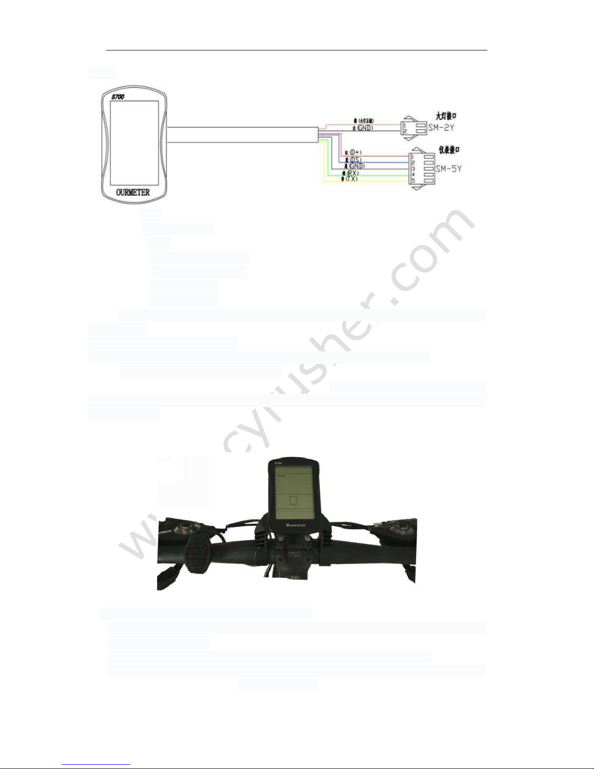
www.cyrusher.com
5 / 29
Red line: VCC
Blue line: Electric lock DS
Black line: GND
Green line: Data receiving line RX
Yellow line: Data sending line TX
Brown line: Headlight DD
White line: Headlight GND
Note: Specific wiring methods and line colors are customized according to customer
requirements.
5.) Physical installation schematic
Fix the instrument LCD display part and external key to the electric vehicle and
adjust the appropriate angles. Connect the instrumentation plug-in to the controller to the
application plug-in, in the case of bike without power. Turn on the power, the electric bike
and the instrument enter a normal operation condition, thus the instrument installation has
been completed.
2. Product Introduction and Function Overview
1.)The two-way communication protocol and external three-way button facilitate the
operation for customers
2.)Speed display: Including real-time speed, MAX SPEED, AVG SPEED.
3.)Kilometer/mile display: setting the kilometers(K/h) and miles( Mph) according to
customers’ habits.
www.cyrusher.com
6 / 29
4.)Intelligent battery display: display the battery’s current power
5.)Headlight control: control the opening and closing of headlights through external
keys
6.)Backlight brightness three adjustment: set backlighting according to customers’
using habits, 1 grade means-darkest, 3 grade means-lightest.
7.)Five gears control: according to customers’ requirements, you can choose the
assisted gears 0-5 by the outer button, and 0 means neutral
gear, no assistance (The default is 5 gear).
8.)Mileage display: the cumulative mileage can be displayed is 0D0, single mileage
TRIP, riding time.
9.)Fault code prompt: the details is in the error code definitions and schedule 1
10.)6KM power-assisted mode: it displays cruising WALK in the 6KM power-assisted
mode
11.)Parameters setting: all parameters can be set by setting the interface, including
gear, wheel.
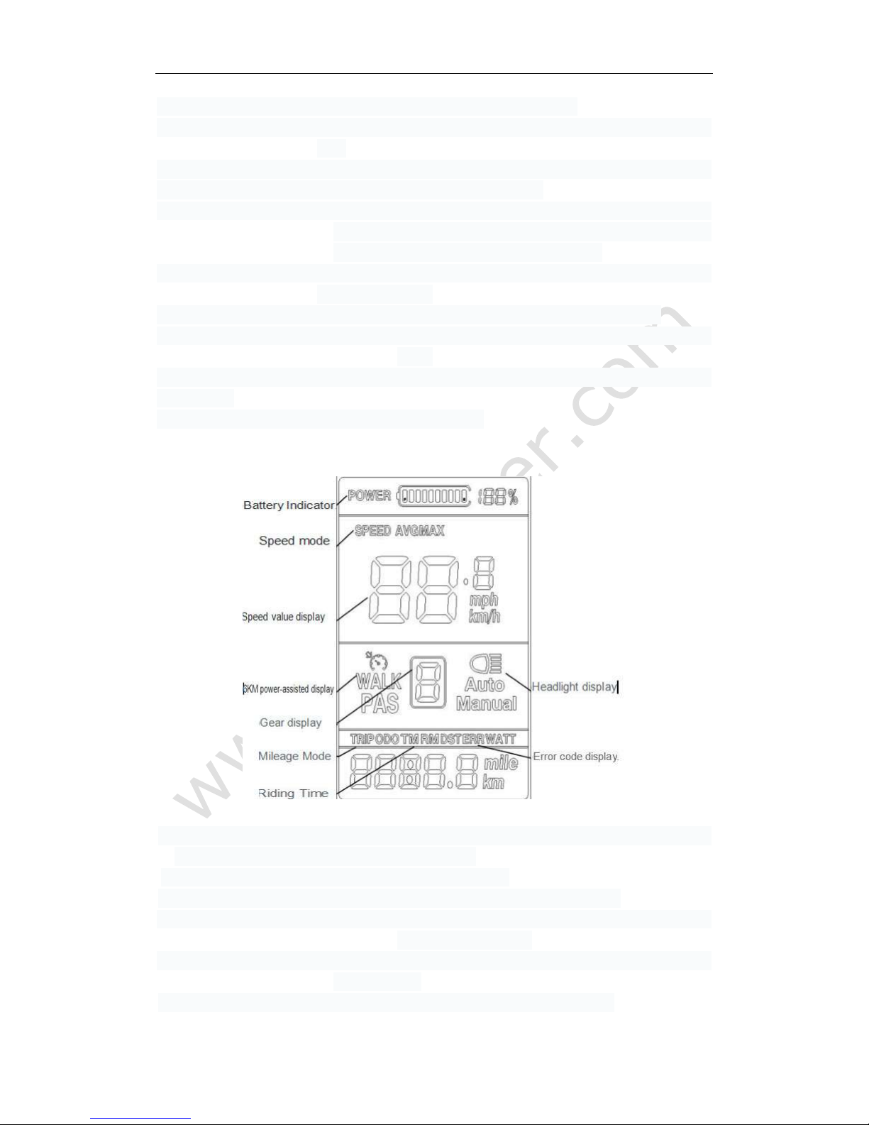
3.Liquid crystal display content and description
1.)Battery Indicator: 10 segments energy indicators, can set the voltage values of each
segment according to customers’ requirements.
2.)Speed mode: AVG SPEED, MAX SPEED, SPEED.
3.)Speed value display: Km/h, kilometres per hour, MPH miles per hour
4.)6KM power-assisted display: it displays cruising WALK in the 6KM
power-assisted mode
5.)Gear display: display the current assisted gear, 0-5, and 0 means neutral gear,
no assistance.
6.)Headlight display:it displays when the headlight and backlight is on.
www.cyrusher.com
7 / 29
7.)Mileage Mode :including the single mileage TRIP and the cumulative mileage 0D0,
8.)Riding Time: displays the riding times
9.)Error code display: ERRO and error code are displayed when the fault is detected
4.External key definition.
LCD-S700 adopts the LCD part and external three - to - button separation in the form
of design, the communication is connected by the bottom lead.
There are three keys, using the key replaces “UP”, replaces
“MORE”, replaces “DOWN”.
5.Instructions for operating methods and functions
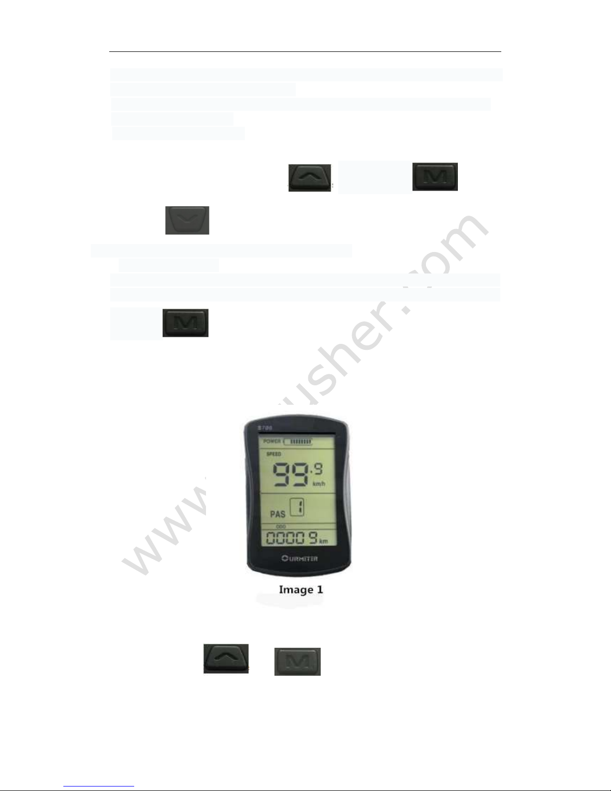
1.)Starting up shutdown
Long-press the MODE button for 3 seconds when the instrument is off, the instrument
fully shows and starts working, turn on the controller power; In boot state , long press
the button for 3 seconds, the cyclocomputer be power off and close the
controller power supply. If there is no riding or not any operations to the instrument in
10 minutes( set time by the user), the instrument will power off
automatically. In the
shutdown state, the power consumption of the instrument and the controller is 0.
The instrument boot display interface is as the image 1 shown.
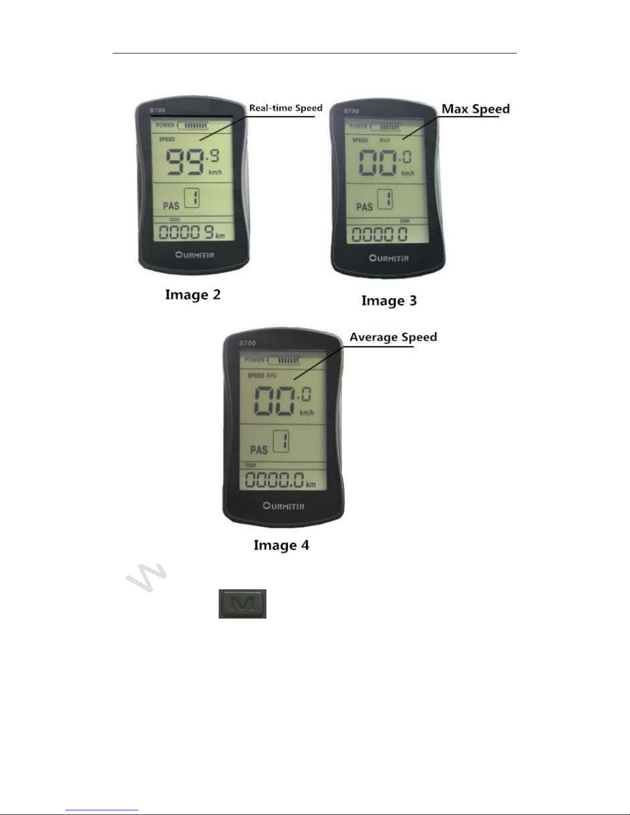
2)Speed Mode Switch
Long press the button and to change the display information of speed,
show the real-time speed → the max speed → the average speed cyclically.
Display interface of speed mode、riding time are as the image 2,3,4 shown.
www.cyrusher.com
8 / 29
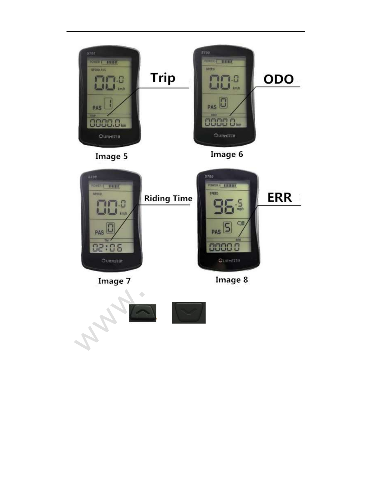
3) Mileage Mode、Riding Time、Error Code switch
Shortly press the button to switch the display of Mileage Mode、Riding Time、Error
Code, show the Trip → ODO → Riding Time → ERR cyclically.
The display interface of switch mode are as the Image 5,6,7,8
shown.
www.cyrusher.com
9 / 29
4) Assistance Stall Chose
Shortly press the button and to switch the assistance stalls, change
the motor assistance power, min stall 1, max stall 5. It is stall 1 by default in boot state, stall 0 is
neutral, which can be seen as the image 9,10
shown.
 Loading...