

OURASET ECOSET 151, ECOSET 302, ASSET 191, ASSET 192 Instruction Manual

Last Update: 2011-June INSTRUCTION MANUAL FOR THERMOSYPHONIC SYSTEMS 1/35
©TANSUG MAKİNA LTD. 2008
TECHNICAL MANUAL FOR
THERMOSYPHONIC SYSTEMS
“CLOSEST TO THE SUN”
SOLAR THERMAL SYSTEMS

Last Update: 2011-June INSTRUCTION MANUAL FOR THERMOSYPHONIC SYSTEMS 2/35
©TANSUG MAKİNA LTD. 2008
INDEX
CHAPTER I ................................................................................................................................................................................... 3
INSTRUCTIONS FOR INSTALLER ............................................................................................................................................. 3
1. INTRODUCTION .................................................................................................................................................................... 3
2. COMPONENTS AND PHYSICAL CHARACTERISTICS ................................................................................................ 4
2.3 Solar panel ....................................................................................................................................................................................... 6
2.3.1 Technical Spec Sheet ........................................................................................................................................... 6
2.3.2 Efficiency Curve ..................................................................................................................................................... 6
2.3.3 Cross Section of the Solar Panels .................................................................................................................... 8
2.4 Technical Specifications of Horizontal Boilers ....................................................................................................................... 9
3. GENERAL INSTRUCTIONS- PREPERATIONS FOR INSTALLATION .................................................................... 13
4. INSTALLATION OF PANELS ........................................................................................................................................... 14
4.1 Placement of Panels .................................................................................................................................................................... 14
4.2 Panel Angle .................................................................................................................................................................................... 14
4.3 Avoiding Shades ........................................................................................................................................................................... 14
5. INSTALLATION OF THE SYSTEM .................................................................................................................................. 15
5.1 Installation of Single- Panel Systems ...................................................................................................................................... 15
5.2 Installation of Double- Panel Systems .................................................................................................................................... 16
5.3
Mounting of Expansion Tank in Inclined Roof ..................................................................................................................... 16
6. MODULAR ROOF-TOP STAND ....................................................................................................................................... 17
6.1 Compatibility .................................................................................................................................................................................. 17
6.2 List of Components used in the structures. .......................................................................................................................... 17
6.3 Description of screws that are used in the mounting of the stands................................................................................ 18
6.4 Assembly of Thermosyphonic Flat Roof Stand (TFR45) ................................................................................................ 18
6.5 Assembly of Thermosyphonic Flat Roof Stand (TFR35) ................................................................................................ 21
Assembly of Thermosyphonic Flat Roof Stand (TFR35) ................................................................................................ 22
7. FILLING THE BOILER..........................................................................................ERROR! BOOKMARK NOT DEFINED.
8. ELECTRICAL ELEMENT ................................................................................................................................................... 27
9. AFLU-S HEAT TRANSFER FLUID .................................................................................................................................. 30
10. CHARGING THE CLOSE LOOP CIRCUIT ..................................................ERROR! BOOKMARK NOT DEFINED.
11. DISCHARGING THE SYSTEM ..................................................................................................................................... 30
CHAPTER II .................................................................................................................................................................. 31
INSTRUCTIONS FOR USER ...................................................................................................................................................... 25
12. SAFETY & SECURITY COMPONENTS ..................................................................................................................... 31
12.1 Primary Circuit (Closed Loop Line): ....................................................................................................................................... 31
12.2 Secondary Circuit (Cold Water Line): ..................................................................................................................................... 31
13. MAINTENANCE .............................................................................................................................................................. 31
13.1 Cleaning Panels ............................................................................................................................................................................ 32
13.2 Pipe Insulation ............................................................................................................................................................................... 32
13.3 Magnesium Anode ........................................................................................................................................................................ 32
14. TROUBLESHOOTING & IMPORTANT POINTS ...................................................................................................... 32
ANNEX 1: PARALLEL CONNECTION OF MULTIPLE SYSTEMS ...................................................................................................... 34
ANNEX 2: SERIAL CONNECTION OF MULTIPLE SYSTEMS ............................................................................................................ 34

Last Update: 2011-June INSTRUCTION MANUAL FOR THERMOSYPHONIC SYSTEMS 3/35
©TANSUG MAKİNA LTD. 2008
CHAPTER I
INSTRUCTIONS FOR INST ALLER
1. INTRODUCTION
Thank you for your choosing an OURASET Solar Water Heating System. Not only
you secured the cleanest, safest and probably the most economic way to obtain hot
water but also you have fulfilled your responsibility against the environment. Buying
an OURASET is a gift to the “PLANET EARTH” as well as to the future generations.
OURASET solar water heater system is designed to provide problem free hot water
for many many years.
This manual has been prepared for two purposes:
• Assist the installation teams for the correct assembly of the system.
• Inform the home-owner about the capabilities of the system, and ensure that
they receive maximum benefit from their OURASET systems throughout its
life time by carrying out correct maintenance.
The manual consists of two chapters:
• Chapter 1 focuses on the characteristics of the system as well as the
assembly of the compa ct system.
• Chapter 2 sets the guidelines for both the installer and the homeowner for
maintenance of and maximizing the benefit from the Ouraset solar water
heating system.
All you need to do is read this manual and follow the installation instructions
carefully.
OURASET has been manufacturing solar boilers, solar panels and integrated
domestic hot water systems for over three decades. Thousands of home owners
around the world are enjoying hot water that comes as a gift of sun.
Until today you have probably been a consumer of energy - now you are a
generating energy on your roof!
Congratulations with your choice and happy sunny days with OURASET on your
roof!

Last Update: 2011-June INSTRUCTION MANUAL FOR THERMOSYPHONIC SYSTEMS 4/35
©TANSUG MAKİNA LTD. 2008
2. COMPONENTS AND PHYSICAL CHARACTERIS TICS
Thermosyphonic Systems at a glance
*Capacity is estimated based on average daily hot water generation capacity calculated on the insulation values between 36th-38th parallel - Mediterranean climate.
Last Update: 2011-June INSTRUCTION MANUAL FOR THERMOSYPHONIC SYSTEMS 5/35
©TANSUG MAKİNA LTD. 2008
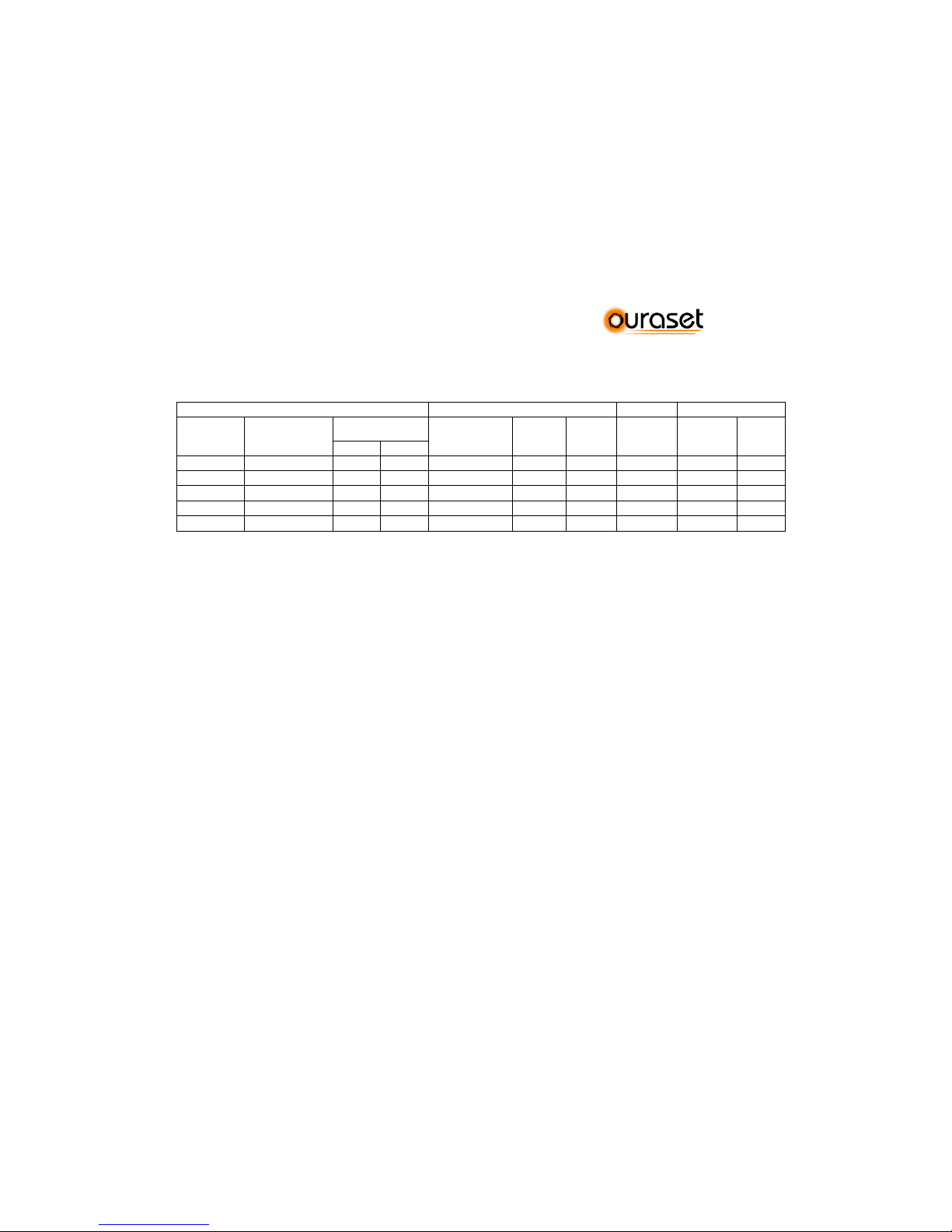
2.2 System Dimensions and Weights*
*Refer to Section 4 : “Shading Scheme” to identify distances for placement of multiple units.
TANK SOLAR PANEL STAND TOTAL WEIGHT
MODEL
DIMENSIONS
(mm.)
Empty
WEIGHT (kg)
DIMENSIONS
(mm.)
QUANTITY
WEIGHT
(kg)
WEIGHT
(kg)
EMPTY
(kg.)
FULL
(kg)
Close
Open
P 121
Ø 500 X 1200
58,0
-
1945x1200
1
40,5
27
125,0
252,0
P 151
Ø 600 X 1000
66,5
53,0
1945x1200
1
40,5
27
134,0
284,0
P 191
Ø 600 X 1200
73,7 62,0
1945x1200
1
40,5
27
141,2
331,2
P 192
Ø 600 X 1200
73,7 62,0
1945x1970 2 65
31
168,7
358,7
P 302CL
Ø 600 X 1800
115,0 90,0
1945x2480 2 81
31
227,0
527,0
* In addition to to standard sets illustrated at section 2, various configurations are shown above. These schemes are illustrative only.
OURASET manufactures systems with different tank configurations only on an OEM basis with sufficient volume.
Last Update: 2011-June INSTRUCTION MANUAL FOR THERMOSYPHONIC SYSTEMS 6/35
©TANSUG MAKİNA LTD. 2008
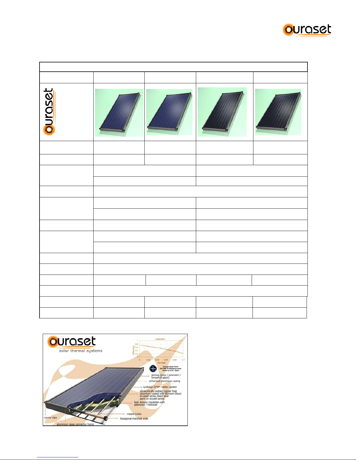
2.3 Solar panel
2.3.1 Technical Spec Sheet
Technical Specifications of the Panels – AA a nd AE S
MODEL AA 950 AA 1200 AES 950 AES 1200
Dimensions
950x1950 x105 mm. 1200x1950x105 mm. 950x1950x105 mm. 1200x1950 x105 mm.
Net absorption area
1,57 m2 2,07 m2 1,57 m2 2,07 m2
Insulation
Bottom : 50 mm Rockwool coated with glass
tissue
Bottom : 50 mm glasswool coated with glass
tissue
Sides : 20 mm glasswool with glass tissue Sides : 20 mm. glasswool with glass tissue
Conductor
Copper absorbers welded to copper tubes by ultrasonic welding method
Absorber Coating
Highly selective blue-sputtered coating Solar matt paint
a: ,95 e: ,05 a:,95 e:,70-90
Glass (4 mm.)
4 mm Low-iron tempered (Prismatic) Tempered
Glass
Characteristics
transmissivity %91 transmissivity %83
reflexivity + absorbtivity %9 reflexivity + absorbtivity %17
Casing
Electrostatic painted extra-durable aluminum extruded prof il e
Bottom
Embossed Aluminum Sheet
Number of Tubes
8 10 8 10
Headers / Tubes
Ø 22 - 10 mm
Weight
33 kg. 43 kg. 33 kg. 43 kg.
Fluid Capacity
1,6 lt. 2,2 lt. 1,6 lt. 2,2 lt.
2.3.2 Efficiency Curve
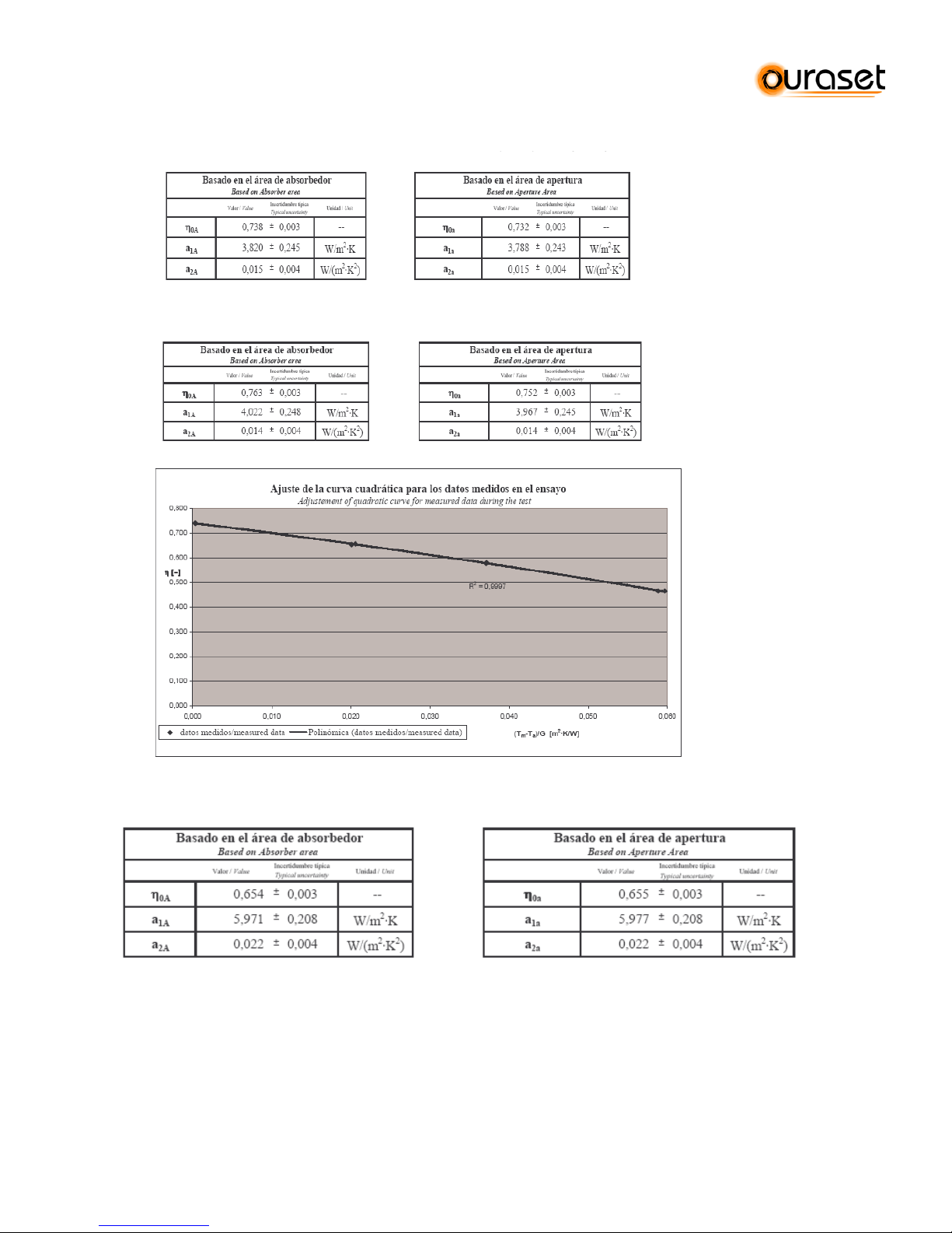
Last Update: 2011-June INSTRUCTION MANUAL FOR THERMOSYPHONIC SYSTEMS 7/35
©TANSUG MAKİNA LTD. 2008
Test Report for AA 1200, by CENER under SOLAR KEYMARK Scheme
Test Report and efficency curve for AA 950, by CENER under SOLAR KEYMARK Scheme
Test Report and efficency curve for AES 1200, by CENER under SOLAR KEYMARK
Last Update: 2011-June INSTRUCTION MANUAL FOR THERMOSYPHONIC SYSTEMS 8/35
©TANSUG MAKİNA LTD. 2008
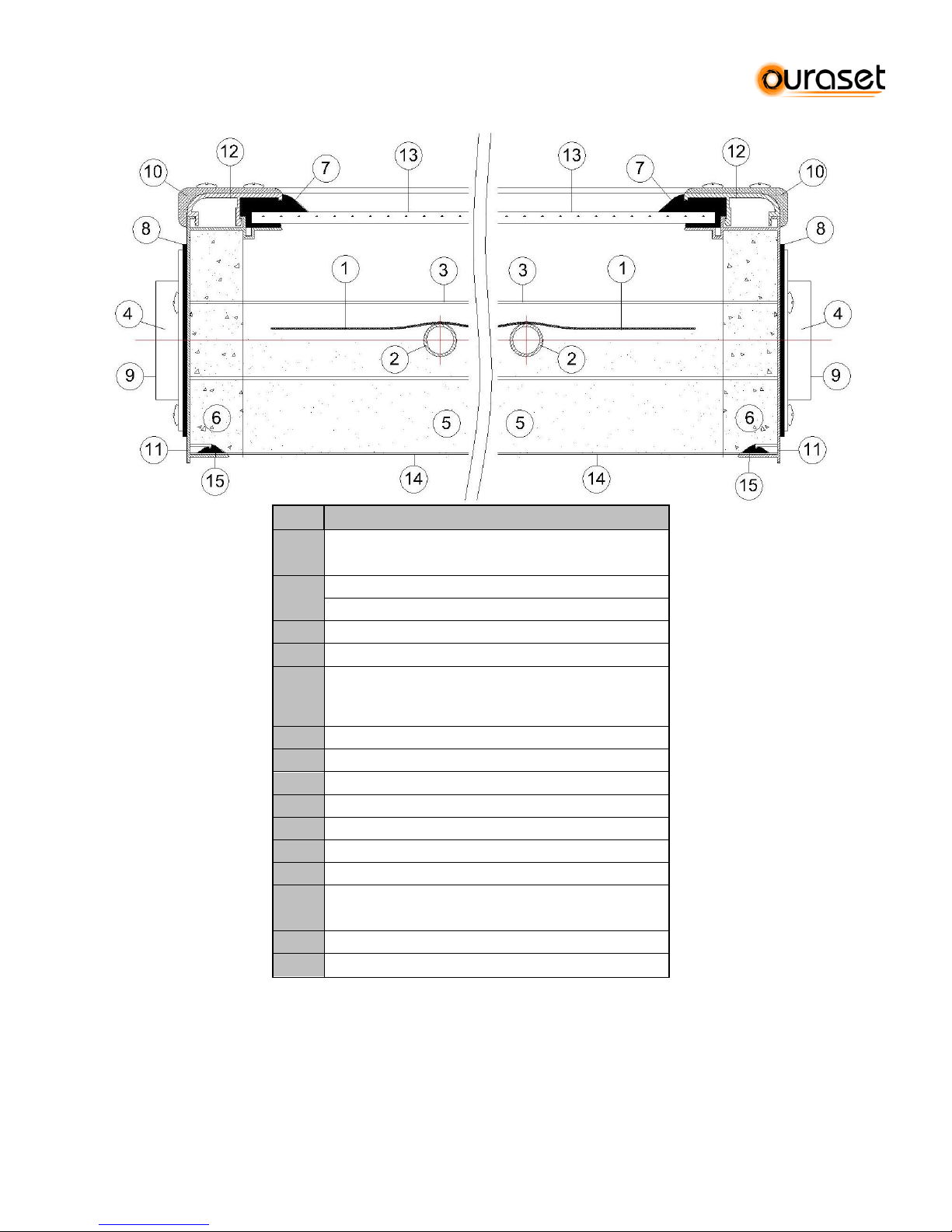
2.3.3 Cross Section of the Solar Panels
ITEM
SOLAR PANEL
1
Black painted (AES) / selective coated (AA)
copper absorber
2
10 channel (1200) - 8 channel (950)
Ø 10 Copper tubes
3
Ø 22 Copper tube header manifold
4
Hexagonal brass union
5
Insulation 50mm
Rock wool W/m °C:0,055 (AA)
Glasswool W/m °C:0,036 (AES)
6
Glasswool insulation 20mm
7
Glass sealing rubber (U-Type)
8
Manifold outlet scaling rubber
9
Manifold hexagonal union outlet cover
10
Corner supports
11
Alum. Extruded profile
12
Alum. Extruded trim
13
Low - iron tempered prismatic glass (AA)
Tempered solar glass (AES)
14
Al. Embossed sheet 0.40mm
15
Back plate sealing rubber
Last Update: 2011-June INSTRUCTION MANUAL FOR THERMOSYPHONIC SYSTEMS 9/35
©TANSUG MAKİNA LTD. 2008
2.4 Technical Specifications of Horizontal Boilers
HIGHLIGHT S OF OU RASET P SERIES
*
Aesthetic Uv resistant ABS Plastic Caps designed for easy handling
*
Minimum heat loss due to dense polyurethane insulation
*
Enatech porcelain enamel coating to ensure hygienic water
*
Electrical heater inlet and cap available
*
Extra-durable external case, color coated galvanized, suitable to locate outdoors
*
Mg anode, enamel protection and inspection/cleaning hole for extended tank life
Code
P 120 P 150 P 190 P 300
Net Capacity
120 lt. 150 lt. 190 lt. 300 lt.
External Casing
*Case: Colorcoated® galvanized steel, coated with transparent folio for protection during
transport
* Caps: UV-Proof ABS plastic
Diameter ( ø )
(mm)
500 mm
600 mm
600 mm
600 mm
Length (L) (mm)
1200 mm
1000 mm
1500 mm
1800 mm.
Tank Body
Material (mm)
Low carbon steel
3 mm
Low carbon steel
3 mm
Low carbon steel
3 mm
Low carbon steel
3 mm
Jacket material
(mm)
Low carbon steel Low carbon steel Low carbon steel Low carbon steel
1,5 mm
1,5 mm
1,5 mm
1,5 mm
Tank Internal
Protection
enatech porcelain
Enamel coating
150-400 micrones
enatech porcelain
Enamel coating 150400 micrones
enatech porcelain
Enamel coating 150400 micrones
enatech porcelain
Enamel coating 150400 micrones
Cathodic
Protection
Magnesium anode rod 50 cm
Test Pressure
(bar)
Body: 9 bar
Jacket: 4 bar
Insulation (mm)
ASSET - Polyurethane Injection (42 kg/m³)
40 -50 mm 40 -50 mm 40 -50 mm 40 -50 mm
Water Inlet –
Outlet
¾” ¾” ¾” ¾”
Last Update: 2011-June INSTRUCTION MANUAL FOR THERMOSYPHONIC SYSTEMS 10/35
©TANSUG MAKİNA LTD. 2008
2.4.1 Horizontal Boilers, Middle connection (M), CLOSE loop (CL)
P 190M / CL
P 300M / CL
DESCRIPTION
NOZZLE
Ф
Cold water inlet
N1
3/4"
Hot Water Outlet
N2
3/4"
Solar Collector Outlet
N3
3/4"
Return to Collector
N4
3/4"
Expansion Tank Kit Connection
N5
3/4"
Air Vent
N6
3/4"
Anode
N7
1"
Electric Resistance Connection
N8
1 1/4"
Cleaning Flange
N9
DN80 TYPE
DIMENSIONS(mm)
ØD
ØD1
ØD2 L P190M
600
480
500
1200
P300M
600
480
500
1795
Last Update: 2011-June INSTRUCTION MANUAL FOR THERMOSYPHONIC SYSTEMS 11/35
©TANSUG MAKİNA LTD. 2008
2.4.2. Horizontal Boilers, Side connection (S), OPEN (OL) or CLOSE (CL) loop
P 120S / CL
P 120S / OL
P 150S / CL
P 150S / OL
P 190S / CL
P 190S / OL
P 300S / CL
P 300S / OL
OPEN LOOP
CLOSE LOOP
DESCRIPTION
NOZZLE
Ф
Cold water inlet
N1
3/4"
Hot Water Outlet
N2
3/4"
Solar Collector Inlet
N3
3/4" Solar Collector Outlet
N4
3/4" Expansion Kit Inlet
N5
3/4" Air Vent
N6
3/4" Anode
N7
1" Electric Element Inlet
N8
1 1/4"
Cleaning Flange
N9
DN80
TYPE
DIMENSIONS(mm)
ØD
ØD1
ØD2
L
P120S
500
380
480
1200
P150S
600
480
500
1000
P190S
600
480
500
1200
P300S
600
480
500
1795
 Loading...