

Page 1
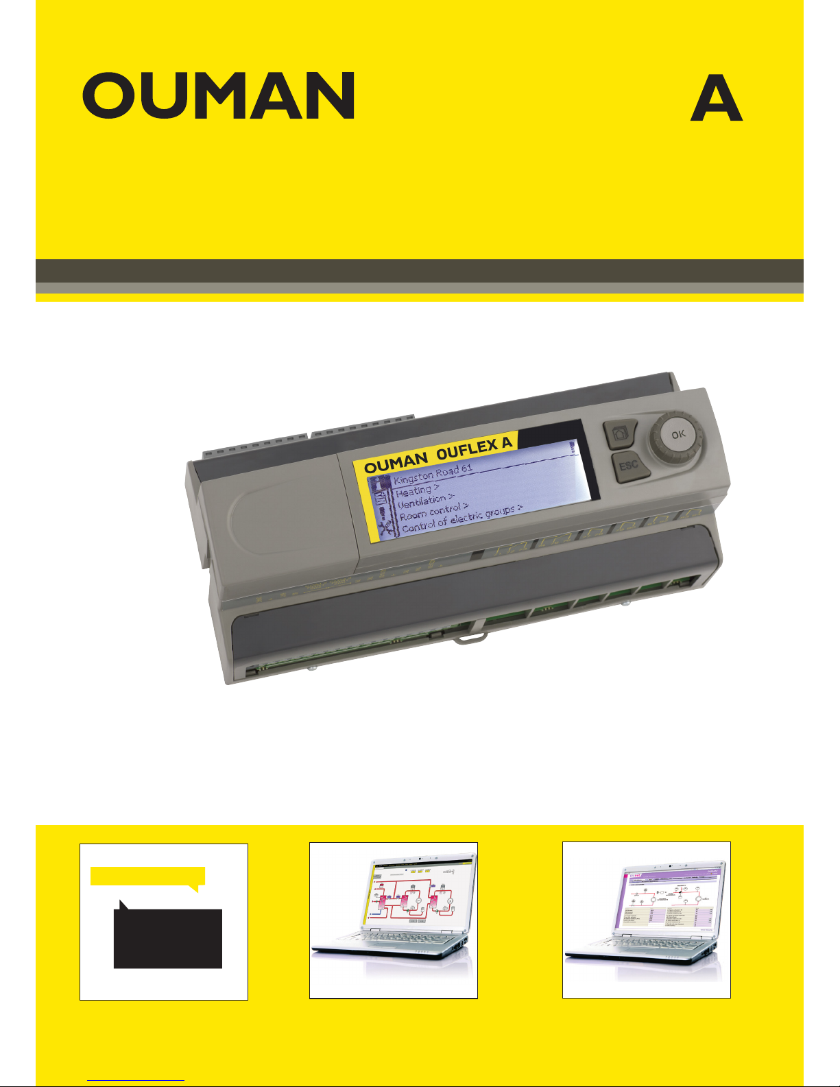
Freely programmable automation device
USER MANUAL
OUFLEX
- Ouflex A is a DIN-rail-attachable, monitoring-, controlling- and regulating device.
- The DIN-standard-compatible structure of the Ouflex A device enables installation
to most common cabinets.
- Detachable strip connectors make installation easier.
Key words:
Active alarms
Alarm history
KEY WORDS
Internet-based on-line control room
for professional remote
control and monitoring (optional).
Local Web Server
remote control and monitoring (optional).
Use of a GSM phone requires that
the GSM modem (optional) is connected to the controller.
OUNET
EH-net
Page 2
2
Ouflex A is a DIN-rail-attachable and freely programmable device designed for monitoring, controlling and
regulating. The device is programmed with Ouflex BA Tool utility and the prepared program is loaded to the
Ouflex device via Ethernet connection. It is possible to increase the number of I/O-points with external I/O-modules via Modbus RTU connections.
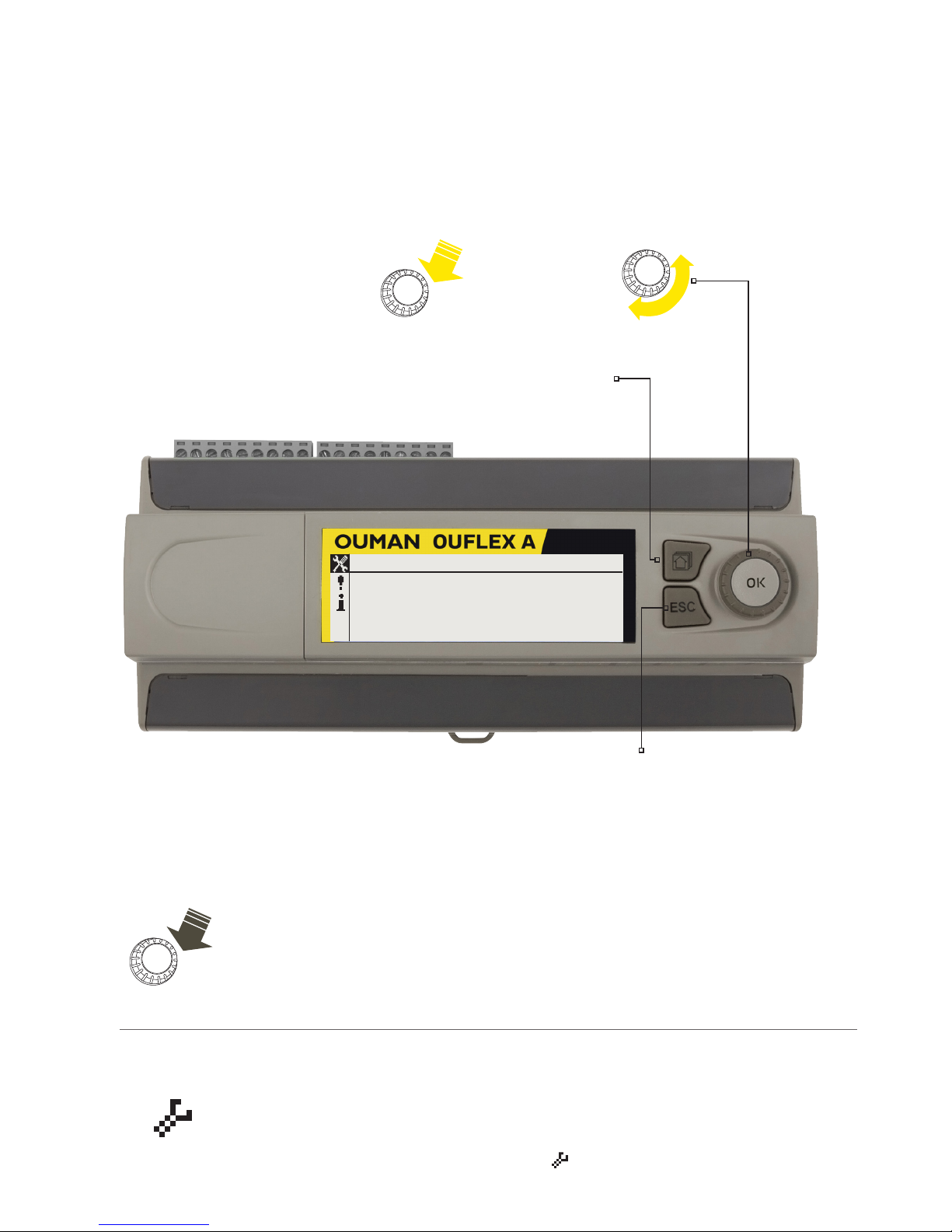
You can move from one function to another by turning the control knob of your OuflexA device. By pressing
the control knob (= OK), you can enter any function to examine it in detail. This way you can see the related
measurements, state information, settings, time programs, etc.
OK
OK
OK
Some of the information in your Ouflex A device may be
hidden. You can see the hidden menus by pressing OK for a
few of seconds. Similarly, you can hide them again by pressing OK for a few of seconds. Hiding information that you
seldom need to change or look into makes the HMI simpler.
When visible, this information is shown indented.
There may be a maintenance code in use in your Ouflex A
device. In this case, you can see the information even when
it’s locked, but you can’t make changes to settings without
entering the maintenance code. Normally, you lock the most
critical settings behind the maintenance code, or settings
that require expertise.
There is a symbol in front of a setting that requires maintenance code.
Press OK
for a few
seconds
Hidden menus
Maintenance code
Turn the control knob
to navigate in the menu.
Press the control knob to
enter the menu and accept the changes.
Control knob and OK
ESC button
Press ESC button to cancel changes or move back to
previous menu. Holding the key down for a few seconds
of time re turns the controller to its basic mode. The display shows the basic view, the background light dims
and the keyboard locks if the locking function is in use.
Time
Date
Language
SMS settings
12:04
>
13.08.2018
>
English
>
System settings
Info button
Page 3

3
Contents
1 System settings .................................................................................................................................................... 4
1.1 Setting date, time and language .............................................................................................................................. 4
1.2 Text message (SMS) settings ..............................................................................................................................4
1.3 Network settings .................................................................................................................................................... 6
1.3.1 IP settings .......................................................................................................................................................... 6
1.3.2 Time settings ....................................................................................................................................................... 7
1.3.3 Access settings ................................................................................................................................................... 7
1.4 Display settings .................................................................................................................................................... 9
1.5 Type info ................................................................................................................................................................. 9
1.6 Lock code .............................................................................................................................................................. 9
1.7 Do backup and restore factory settings ................................................................................................................. 10
1.8 Log ........................................................................................................................................................................ 10
2 Alarms ....................................................................................................................................................................11
3 Point information ................................................................................................................................................14
3.1 Wiring info ........................................................................................................................................................... 14
3.1.1 Measuring point control/ manual control ..........................................................................................................14
3.2 Bus points ........................................................................................................................................................... 14
3.3 Time programs .................................................................................................................................................... 15
3.3.1 Present value .................................................................................................................................................... 15
3.3.2 Weekly schedule .............................................................................................................................................. 16
3.3.3 Special days .................................................................................................................................................... 17
3.3.4 Exception schedule ........................................................................................................................................... 17
4 Settings .................................................................................................................................................................18
5 Naming ..................................................................................................................................................................19
6 Communication via a mobile phone ..................................................................................................................19
7 Ouex A device I/O connections and structure .................................................................................................20
Extension units ....................................................................................................................................................22
Technical information ...........................................................................................................................................24
Page 4
4
1.2 Text message (SMS) settings
Use of text messaging requires that the Ouflex A is connected to a
GSM modem (additional equipment).
System settings > SMS settings
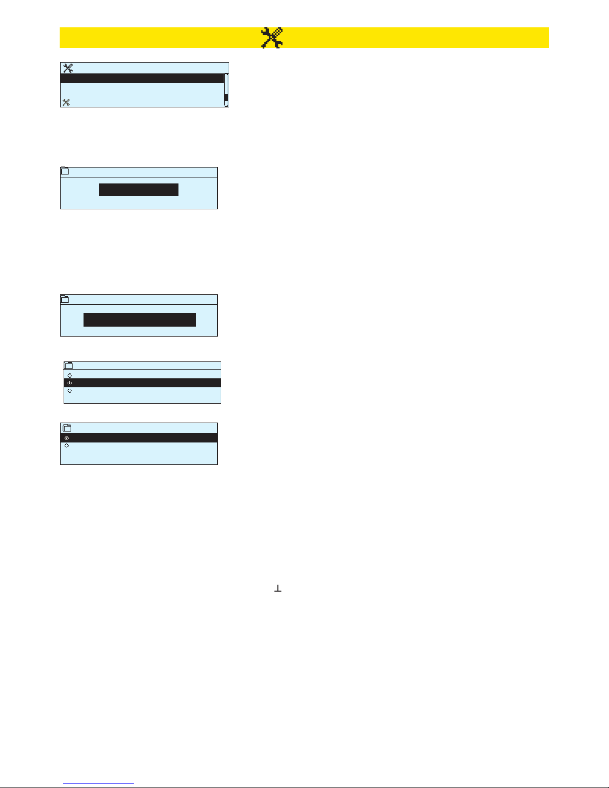
1 System settings
System settings include setting the time, date and language, as well
as text message (SMS) settings, network settings, display settings and
device type information.
Time 17:01
Date 13.08.2018
Language English/English
Daylight saving On
>
>
>
>
Time
19:44
hh:mm
Enter the hours
1.1 Setting date, time and language
It is important that time and date are correct. Alarm information, for
instance, shows when an alarm has activated and inactivated. It is
highly recommendable to ensure that time and date are correct when
you are making time programs with the weekly program or special
calendar. The device clock takes daylight savings and leap years into
account automatically. The clock has a backup for power outages lut
to three days.
Hours and minutes can be set separately.
1. Set hours and press OK to accept.
2. Set minutes and press OK to accept.
3. Press Esc to cancel and exit if needed.
You can change the HMI language here if device has more than one
language.
System settings > Time
System settings > Language
Language
Suomi/Finnish
English/ English
Svenska/ Swedish
System settings
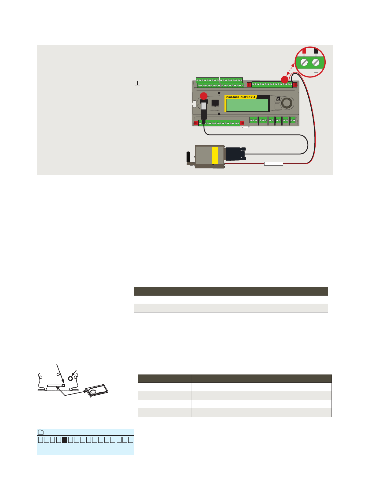
Take the GSM modem into use:
1. Enter your SIM card PIN code.
2. Switch the device o.
3. Connect the modem. Connect the modem USB connector to the device USB host connector. Connect the modem
power supply to the device conectors 93 (+) and .
4. Switch the power on. The controller initializes the modem and detects the message center (the message not
visible on the display).center number is
5. Check the signal strength and status of the modem from the controller display.
6. Enter Device ID (optional).
7. Test the SMS communication. Send a message to Ouflex A: Keywords. If the controller replies with a message
containing a list of key words, text message communication is ok. If the controller doesn’t send a text message, make power cut and turn it back. Retest the text message communication. If communication fails to verify
that the message center number has not been manually entered. Press and hold ok for the hidden menus to
open. If the messagecenter number is assigned, delete the number. The number can be removed most conveniently by placing the first character in place “blank” and then pressing for a long time OK. Then use the system as powerless and turn it on again, and the controller automatically retrieves the message center number
(the number does not appear on the display). Test for communication.
Date
Mon 13.08.2018
dd.mm.yyyy
Enter the day:
1. Set day and press OK to accept (name of weekday is updated automatically).
2. Set month and press OK to accept.
3. Set year and press OK to accept.
4. Press Esc to exit.
System settings > Date
System settings > Daylight saving
Daylight saving
On
Off
You can hide/show this setting by pressing OK for a few seconds.
By selecting Daylight Saving Time, Ouflex A automatically goes into
summer and winter time.
Page 5
5
Device ID
0
O U 0 1
When Ouflex A device starts up, it will automatically detect whether the modem is connected or not and then initialises modem.
You may give your Ouflex A device a device ID. In SMS communication, always type the device ID in front of the keyword
(e.g. OU01 MEASUREMENTS. Note the empty digit between device ID and
the keyword.)
Signal strength is expressed with description: ”Excellent”, ”Good”, ”Moderate”,
”Low”, ”Very low” and ”Initialization failed”. If signal strength is “Very low” or “No
network”, try changing the modem’s location or use an external antenna.
If the unit displays ”Initialisation failed,” check that the SIM card is correctly
installed.
Enter Ouflex A device the same PIN as as the GSM modem’s SIM card PIN.
Approve: Press OK a number of seconds
Cancel: Press ESC a number of seconds
1. Connect the modem USB-connector to
the device USB host connector.
2. Connect the modem power supply to
the device conectors 93 (+) and .
When connect modem supply to
Ouflex A connectors Ouflex A reboot
automatically.
Signal strength:
SMS PIN:
Modem status:
Device ID:
SIM card status:
Ouman GSM modem is connected to modem using an USB cable. The modem
has a fixed antenna that can replaced with to an external antenna with a 2,5m
cord (optional equipment) if needed.
Mode Explanation / Instructions
Connected The modem is ready for use.
Not connected The modem is not connected or the connection is incorrect
Mode Explanation / Instructions
Unregistered
The subscription agreement is not valid.
Registered
The SIM card is ready for use.
PIN error
Incorrect PIN code. Enter the SIM card PIN code in Ouflex A device.
PUK The SIM card is locked (PUK code).
Press the small black SIM card release button with, for example, a pen tip. SIM card
holder pops out. Pull out the SIM card holder. Do not try to remove SIM card holder
without pressing the SIM card release button first!
Insert SIM card into the slot and make sure it settles properly. Push the slot back to
its place. Enter the SIM card PIN code in Ouflex A device. Make sure PIN inquiry is in
use in the SIM card.
You can check the status of the modem also on the modemLED indicator light.
SIM card slot
SIM card release button
Antenna
mounting
point
ESC
93
1
2
Page 6
6
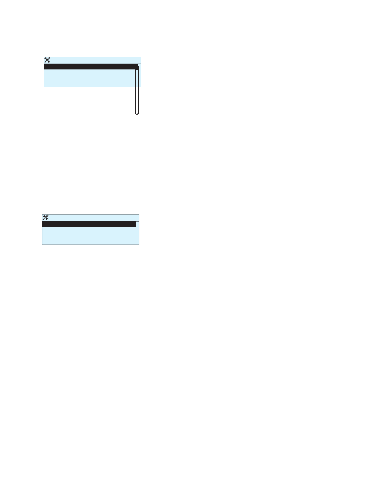
Setting the IP address manually:
1. Go to DHCP and press OK.
2. Select ”O” and press OK to accept selection. If DHCP function is
on, manual changes in ”Subnet mask”, ”Gateway address”, ”Name
server address” and ”IP address” will be ignored.
3. When set IP-settings manually you need to ask correct settings in
that LAN admimistarator.
OBS. Never try to guess the correct settings. Incorrect settings
cause problems, and the network is work properly.
4. Select ”Update network settings”.
IP settings
DHCP Off >
Gateway adress 0.0.0.0 >
Subnet mask 0.0.0.0 >
IP address 0.0.0.0 >
Nameserver address 0.0.0.0 >
Update network settings >
IP settings
Setting the IP address using DHCP function:
1. Go to DHCP and press OK.
2. Select ”On” and press OK to accept selection.
3. Wait approximately one minute. If DHCP is still ”O” after one minute,
setting the IP address and network settings was not successful. Either the settings used previously or factory settings have been taken
in use. In this case, the device does not necessarily function in the
network. The reason for this is usually that the required DHCP service is not in use in the network, or it is out of order, or the network
cables have not been connected properly. Check the network cable
connections and/or make sure DHCP service is in use.
4. If DHCP is ”On”, network settings were successfully chanced and
the device now functions in the network. Device IP address is
shown on display.
System settings > Network settings > IP settings
1.3.1 IP settings
1.3 Network settings
There are two alternative ways to set the Ouflex A device IP address
and network settings:
1. IP address is retrieved via DHCP function. This requires that DHCP
service is in use in the network and network cables have been
connected.
2. IP address is set manually.
System settings > Network settings
Network settings
IP-address x.x.x.x >
Hostname
Co nn ec ti on status Of in e >
IP settings >
Time settings >
Access settings >
Modbus TCP/IP >
SNMP >
FTP Off >
Modbus RTU slave (COM3 (A2/B2)) >
Modbus RTU master (COM2 (A1/B1)) >
Modbus RTU master (COM1 (RJ45 in the end of devi ce)) >
Device has fixed Hostname. Hostname can be used to connect to device from Ouflex tool or Ounet.
Connection status indicates whether Ouflex A device is in the network
or not. Ouflex A device can be connected to a local network or the
Internet. If you use a protected VPN connection using OUMAN Access
service, the controller displays the network mode OUMAN Access.
The Ouflex A device should not be connected to a public Internet
network without a firewall!
Page 7
7
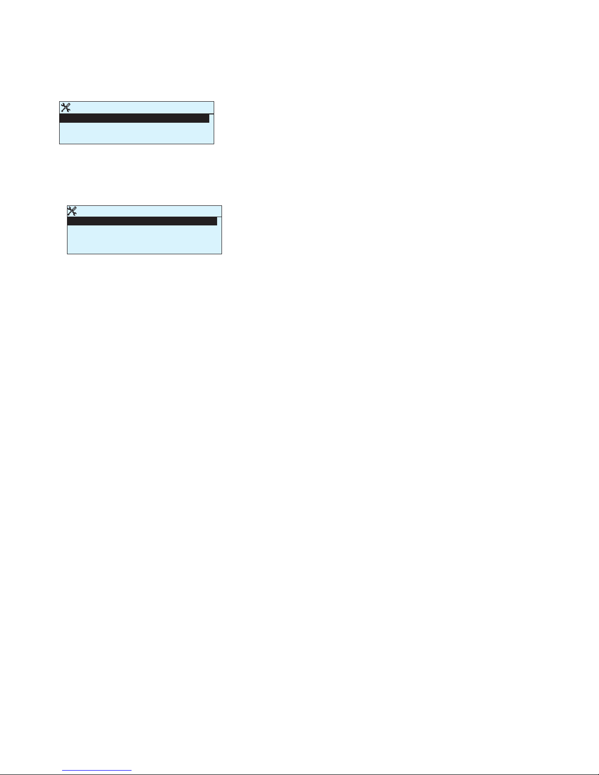
System settings > Network settings > Time settings
Time settings
NTP ser ver 3.. poo l. ntp .o rg >
NTP server 2 83.145.237.222 >
Time zone 2 >
Daylight saving On >
1.3.2 Time settings
Automatic time update from the network on two dierent time servers. If no access to the primary NTP server is available, the device uses the NTP server 2 server. You can change the time zone. In
Finland, zone 2 (+ 2h) is used. The daylight saving is as a default on
the device. In this case, the device will automatically switch from
normal to summer time according to calendar.
Access settings
Access Off >
Access IP 0.0.0.0
Access name
Connection satus Ouman Access
OUMAN ACCESS – service enables you to make a remote connection
(useful with Ounet use) to Ouflex device from internet without any
extra hardware. All you need is a normal internet-connected LAN
with firewall and you have to ensure that certain ports to Internet
are open.
OUMAN ACCESS- service is “o” by default in Ouflex A.
OUMAN ACCESS- service is taken in use in following way: Ouman
salesperson feeds in the target and billing information to the Ouman
system and activates the service based on the serial number of the
Ouflex A device. After that, you have to activate the ACCESS service
from the device.
OUMAN ACCESS- device can be connected to LAN if following conditions are fulfilled:
1. LAN is routed via Internet
The Access service operates on the Internet so the Access service is not
available if the device is not connected to the Internet. The Access device
examines the availability of Internet connection by sending a Ping packet to
the Internet server at 3-minute intervals.
The network must allow the ICMP outwards from any port and the receipt of
the reply message to the same port.
2. The VPN protocol used by Access service outwards is not blocked
The Access service is based on the VPN connection which the Access device
creates to the Access server.
The network must allow the UDP outwards from any port to the port 1194 and
the receipt of the reply message to this port.
3. Time service protocol outwards is not blocked
The Access service works only when the clock in the Access device shows
the correct time. The clock is set to the correct time automatically from the
network using the NTP protocol.
The network must allow the UDP outwards from any port to the port 123 and
the receipt of the reply message to this port.
System settings > Network settings > Access settings
1.3.3 Access settings
Page 8
8
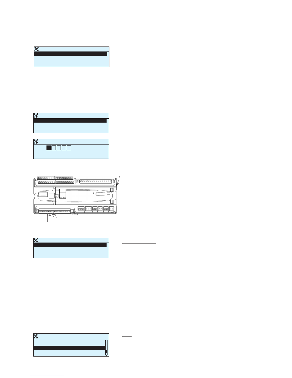
Modbus TCP/IP
Modbus TCP port (internal registers) 5 0 2 >
Max connections 5 >
Idle timeout 0 >
Function active On >
Modbus TCP_IP_Gateway >
SNMP
IP address >
Functon active On >
Modbus TCP server settings are changed via Modbus TCP/IP settings.
It is possible to communicate with an Ouflex A device and the Modbus/RTU slave devices connected to it via Modbus TCP/IP interface.
Modbus TCP port (internal registers): Port number 502 is reserved
for communication of Ouflex A device. Information of Modbus registers of Ouflex A device are read through this port. Recommendation
is that the value should not be changed unless there is a compelling
reason.
Max connections: It is possible to decrease server load by changing
this setting that defines the maximum number of simultaneous connections from dierent IP addresses to the server. Recommendation is
that the values should not be changed unless there is a compelling
reason.
Idle timeout: This setting defines the time after which the server closes an inactive connection. Recommendation is that the value should
not be changed unless there is a compelling reason.
Allowed address: It is possible to improve the information security
of the system by taking permitted connection address into use. If the
value is 0.0.0.0, connections to the server are permitted from any IP
address. If you define one permitted connection address, connections
to the server are not permitted from any other IP address.
Function active: This selection either enables or disables the entire
Modbus/TCP communication.
A1,B1
RJ45
A2,B2
Modbus TCP/IP settings
System settings > Network settings -> Modbus TCP/IP
System settings > Network settings -> SNMP
Modbus TCP/IP gateway -> Modbus RTU master
System settings > Network settings -> Modbus TCP/IP-> FTP
It is possible to connect three Modbus/RTU buses to an Ouflex A device. Each bus has its own port address that is used to communicate
with bus devices via Modbus/TCP interface. ”Modbus RTU master 1
(A1,B1)” setting defines the TCP/IP port for Modbus 1. Similarly, Modbus RTU master 2 (A2,B2)” setting defines the TCP/IP port to Modbus
2. ”Modbus RTU master (RJ45)” setting defines the TCP/IP port that
functions as a gateway to Ouflex I/O extension bus. Gate addresses
can be changed.
SNMP settings: SNMP function can be used to send notifications
about alarms activating, inactivating and being acknowledged via
SNMP protocol to a desired server.
IP address: The IP address of the target server to which messages
are sent.
Function active: This selection either enables or disables the entire
SNMP function.
Retry delay (min): If the alarm is not acknowledged in Ounet, Ouflex
A sends SNMP messages again. The retransmission is limited to max
240 minutes. By setting the Retry delay to 0, the retransmission is is
disabled.
FTP
Ouflex A device support also FTP but read only mode. So cases this
can be use to read Modbus templates from device to Ounet.
Network settings
Modbus TCP/IP >
SNMP >
FTP Off >
Modbus RTU slave >
Modbus TCP/IP gateway
Modbus RTU master 1 (A1, B1) 504 >
Modbus RTU master 2 (A2,B2) 505 >
Modbus RTU master 3 (RJ45) 503 >
Modbus RTU master 1 (A1,B1)
Approve: Press OK for a number of seconds
Cancel: Press ESC for a number of seconds
0 0 5 0 4
Page 9
9
1.4 Display settings
1.5 Type info
Type information shows the device platform version and application
version. The name of application and version is determined by the user
of OuflexTool. This information is useful especially in case of maintenance or upgrade.
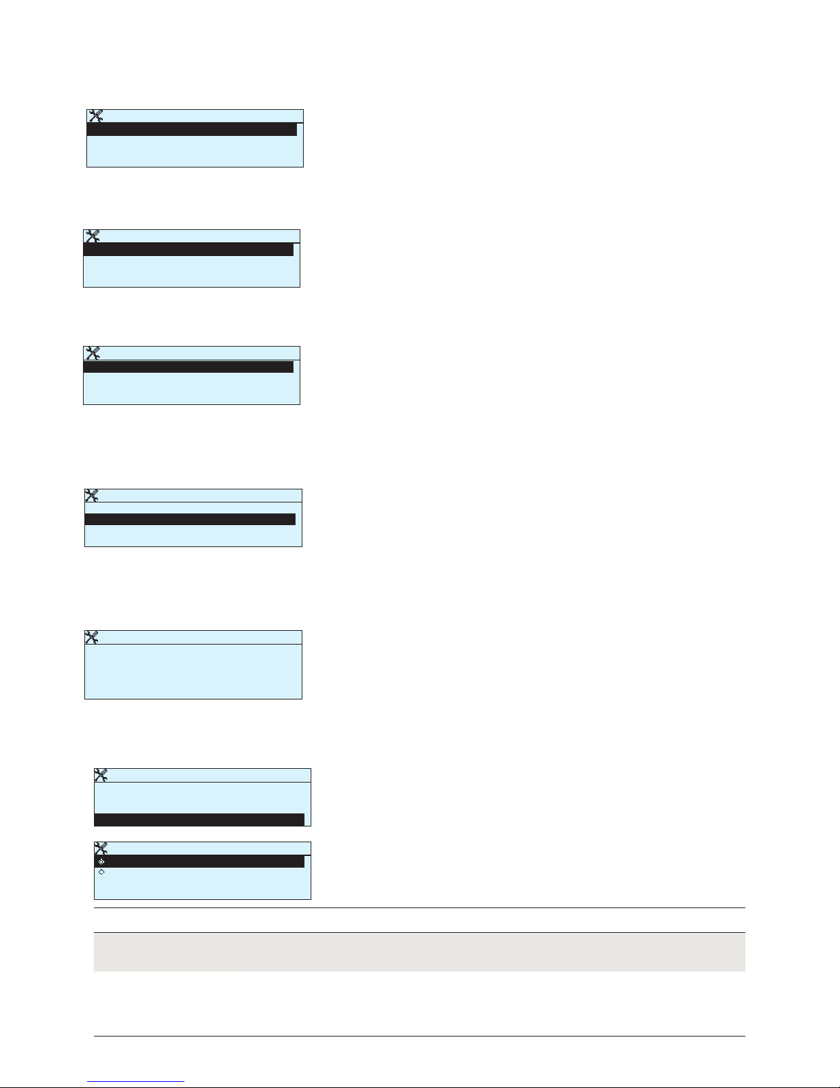
System settings > Display settings
System settings > Type info
Display settings
Display version xxxxx
Contrast 75 >
Type information
Serial number xxxxxxx
Application version 0.0.0
Ou man Ou ex 0.0 .0
Display 1 .1.1
Platform SW
75 >
You can adjust contrast. If you wish the display to be brighter, set a
smaller numerical value. The setting range is 50… 100. The display
changes after you have confirmed the setting change.
1.6 Lock code
System settings > Lock code
Not in use
In use
You can read Ouflex A device information and change settings.
You can read Ouflex A device information but you can not change settings without entering the lock code. The factory setting of lock code
is 0000. If you take lock code into use, change the code for security
reasons.
Lock code function Description
Lock code
Display settings >
Type information >
Connections, meas. and states >
Lock code Not in use >
Lock code
In use
Not in use
>
If you take lock code into use, you can read Ouflex A device information
when the device is locked, but you can not change settings. It is recommended, for example, that you take lock code into use if the device is
located so that anyone could reach it and change settings (e.g. deactivate burglar monitoring). Locking the device and changing the lock
code prevents unauthorized use of the device.
Modbus RTU master 1 (COM2 (A1/B1))
A1/ B1
Baudrat e 960 0 >
Data bits 8 >
Stop bits 1 >
Parity None >
Delay between packages 10 ms>
Modbus RTU slave (COM3 (A2/B2))
A2/ B2
Address 1 >
Baudrat e 960 0 >
Data bits 8 >
Stop bits 1 >
Parity None >
Modbus RTU master 3 (COM1 (RJ45))
RJ45
Baudrat e 960 0 >
Data bits 8 >
Stop bits 1 >
Parity None >
Delay between packages 1 ms >
System settings -> Network settings -> Modbus RTU slave (COM3 (A2/B2))
System settings -> Network settings -> Modbus RTU master 1 (COM2 (A1,B1))
System settings -> Network settings -> Modbus RTU master 3 (COM1 (RJ45 in the end of device))
Ouflex A device can be connected to Modbus RTU bus as a master or a
slave device. Bus settings are configurable. Every device connected to
the same bus must have unique address and same baud rate, number of
data bits, number of stop bits, and parity.
If a device is unstable on the bus, it may be possible to get the bus trac
stable by increasing the delay between the packets.
Page 10
10
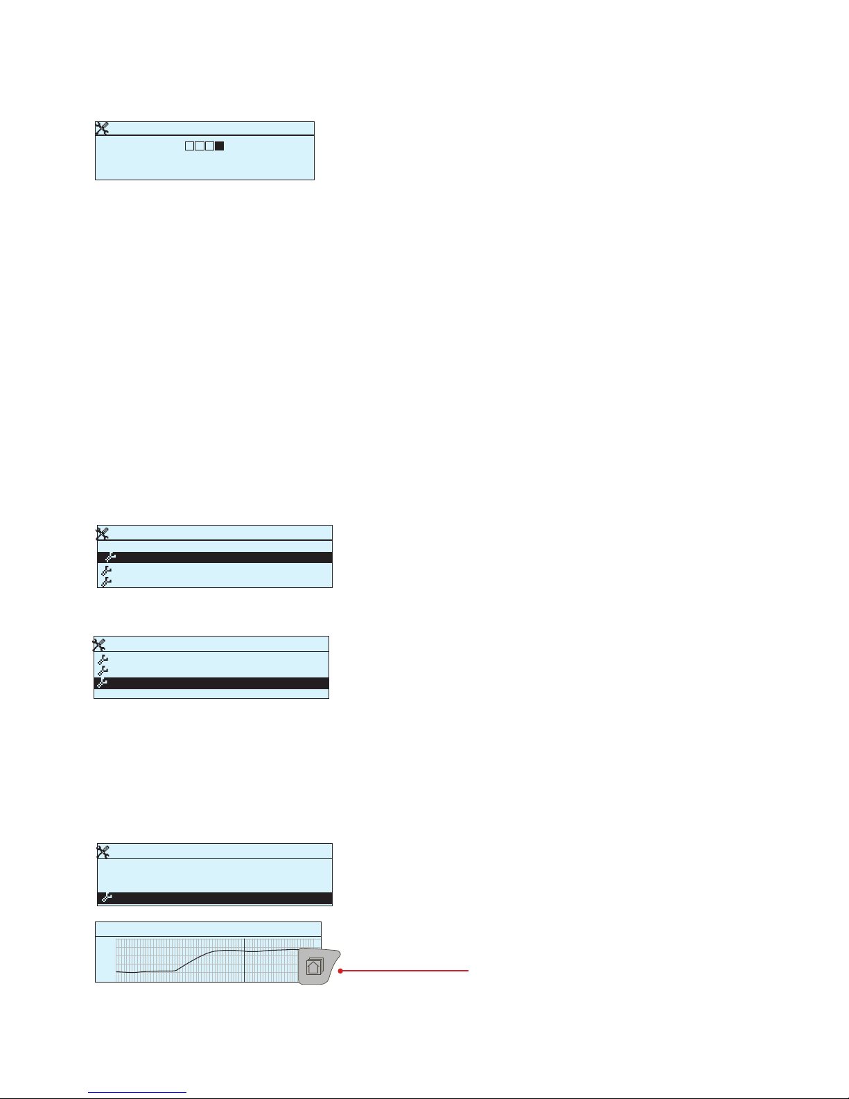
1.8 Log
System settings -> Log
Press OK for a number of seconds to show hidden settings. If you want
to restore factory settings, restore backup or do backup you have to
enter the service code. You can also reset the measurement history.
System settings
System settings
Lock code Not in use >
Restore factory settings >
R Restore backup
>
Do backup
>
Restore factory settings >
R Restore backup
>
Do backup
>
Log >
System settings
Restore factory settings >
R Restore backup
>
Do baciup
>
Log >
It is recommended to make a backup as soon as Ouflex A has been
taken into use and property-specific settings have been made. You
may also restore factory settings.
All the parameters which are saved in the non-volatile memory will
be included in the backup. Such parameters are e.g. all the setting
values, time programs and namings.
If you have taken lock code into use, you may change the code.
System settings > Change lock code
Ouflex A device asks you to enter the current code. The factory setting
of lock code is 0000.
Turn the control knob and press OK to accept each number.
Press ESC to return to the previous square.
Press OK for a number of seconds to accept the code.
Press ESC for a number of seconds to cancel
Give lock code
0 0 0 0
Approve: Press OK for a number of seconds
Cancel: Press ESC for a number of seconds
1.7 Do backup and restore factory settings
It is recommended to make a backup as soon as Ouflex A has been
taken into use and property-specific settings have been made. You
may also restore factory settings.
System settings -> Backup
System settings -> Restore factory settings
System settings -> Do backup
Show measurement history on display.
To see trend line, select the wanted measurement and
press Info button.
You can also rename the measurement.
To delete log from device, select ”Reset measure history”.
Trend log 28.01 08:26:19 [ 34.7 °C ] ( s )
38
28
Page 11
11
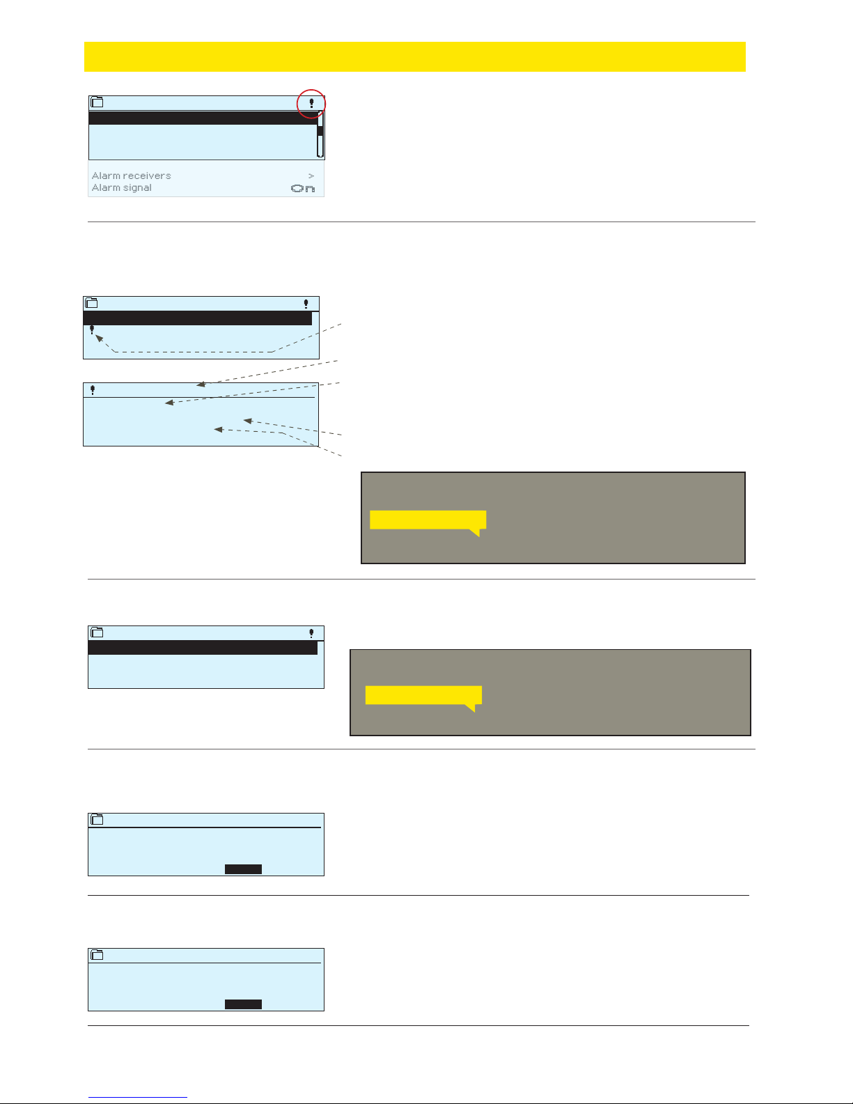
You can see the cause of the alarm, where the alarm has come from and when
the alarm has become inactive. (e.g., 02.11.2017 at 10:11: 42). The last 10 alarms
can be seen in Alarm histor y.
Ouflex A requests confirmation before deleting alarm histor y.
Ouflex A requests confirmation before acknowledging all alarms.
Conrm
Conrm
Empty alarm history
Yes No
Acknowledge all alarms
Yes No
Alarms -> Alarm history
Alarms -> Acknowledge all alarms
Alarms -> Reset alarm history
2.2 Alarm history
2.3 Acknowledge all alarms
2.4 Reset alarm history
Send message: Alarm history
The controller sends a message showing the
last alarms. Message is informational.
Alarm history
02.11.2017 10:11:42 Sensor fault H1 Supply w
02.12.2017 11:22:40 Sensor fault H2 Return w>>
2
ALARM HISTORY
Deviation alarm
PR 1 GROUP 1
H1 Supply water temp. =10.2 °C
Received: 08.12.2017 02:27
Press OK to acknowledge the alarm
Every active alarm is shown in a separate row, where you can see
when the alarm has become active. Press OK to get more information about the
alarm.
Alarms > Active alarms
2.1 Active alarms
Send message: Active alarms
The controller sends a message showing all
active alarms. Message is informational.
Alarms
Active alarms
Alarm history
Acknowledge all alarms
Reset alarm history
Routing schedule
Alarm receivers
Alarm signal
>
>
>
>
>
>
On
>
Active alarms
07.12.2017 12:24:52 H2 Risk of freeze
08.12.2017 01:12:40 Sensor fault H1 Return>>
2
2
• An exclamation mark in front of the date shows that the alarm has
been silenced by pressing Esc.
• The heading of the alarm view shows the reason for the alarm.
• You can also see, what is the alarm priority (1 ...5 ) and what
alarm group it belongs to (1...10)
• What location the alarm is coming from
• The time, when the alarm was activated.
ACTIVE ALARMS
2 Alarms
If Ouflex A device is connected to a GSM modem, you can communicate
with Ouflex A device via text message.
If Ouflex A device is connected to a GSM modem, you can communicate
with Ouflex A device via text message.
In the alarm menu of Ouflex A device, you can check the active
alarms and what alarms have been active. The number of active
alarms will is shown in the right corner of the main view.
In Ouman Tool it is possible to specify if the alarm acknowledgement is required or not. If not required, the alarm will disppear of
active alarms when the cause of the alarm has disappeared even if
the alarm has not been acknowledged.
Page 12
12
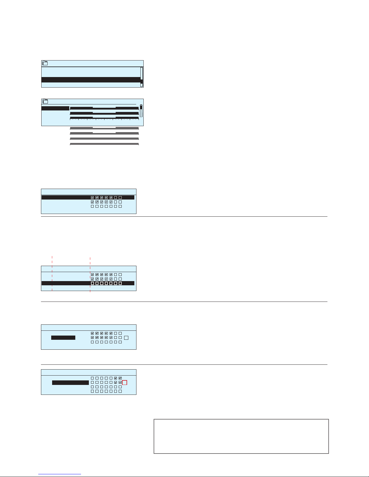
Alarms > Routing schedule (SMS use only)
2.5 Routing schedule
You can see where alarms are currently being routed in the routing
time schelude display. You can also set up a routing schedule for
each alarm group.
You can create a weekly schedule for each alarm group. Weekly
schedule has a general graphic view and an editing view, where
you can see to which alarm team each alarm is directed at dierent
points of time. In the graph, alarm teams are distinguished from
each other by the thickness of the black bar.
Editing view
Time M ode
Time M ode
Time M ode
M T W T F S S
M T W T F S S
M T W T F S S
OK
Deleting a switch time:
1. Turn the control knob to move to the switch time you wish to delete and press OK.
2. Press OK at the selected alarm team and select ”Delete switch
time”
3. Press OK at the end of the row.
4. Press Esc to exit.
1. Set switch time
2. Set alarm team 3.Select day(s)
Time M ode
08:00 Team 1
21:00 Delete switch time
00:00 Add new
M T W T F S S
OK
Browsing a weekly program:
An editing view opens, and it shows all the switch times and also to
which alarm teams alarms are routed at these times on the chosen
days.
Turn the control knob to browse a weekly program. If you wish to
see the exact switch times and names of alarm teams, or if you
wish to edit, remove or add switch times, press OK at any weekday.
Adding a new switch time:
1. Press OK at the “Add new” row.
2. Press OK. Set the switch time for alarm routing (set hours and minutes separately) and press OK.
3. Press OK and then turn the control knob to set the alarm team or
the ”No routing” option. (No routing selection means that alarms
will not be forwarded.) Accept by pressing OK.
4. Press OK at each weekday you wish to choose.
5. Press OK at the end of the row to accept the new time program.
6. Press Esc to exit.
Editing a weekly program:
1. Turn the control knob to move to the value you wish to change
and press OK.
2. Turn the control knob to make the time and alarm team changes.
Press OK to accept.
3. Press the OK button to change the day of the week.
4. Press Esc to exit.
Graph
This example shows that group 1 alarms are always forwarded. During business hours (Monday - Friday 8:00 a.m. - 4:00 p.m.) alarms are
forwarded to dierent teams than during evenings and weekends. More detailed information is shown in the ”Editing view”.
Monday
>
Tuesday
>
Wednesda
>
Thursday
>
Friday
>
Saturday
>
Sunday
>
0 3 6 9 12 15 18 21 24
Group 1 Weekly schedule
08:00 Team 1
16:00 Team 2
00:00 Add new
08:00 Team 1
16:00 Team 2
00:00 A dd new
08:00 Team 1
16:00 No routing
00:00 Add new
If alarms are routed, alarm information is sent to the alarm team by
text message. Alarms are relayed according to the alarm routing
time schedule. You can acknowledge an alarm by sending the
same message back to the Ouflex A.
Routing schedule
Group 1 Weekly schedule
Group 1 Alarm routing now Team 1
Group 2 Weekly schedule
Group 2 Alarm routing now Team 1
>
>
>
>
Page 13
13
Phone number 1
Approve: Press OK for a number of seconds
Cancel: Press ESC for a number of seconds
+ 3 5 8 4 0 8 4 0 0 0 0
Tea m 1
Phone number 1 >
Phone number 2 >
Phone number 3 >
Phone number 4 >
Alarm receivers
Team 1 >
Team 2 >
Team 3 >
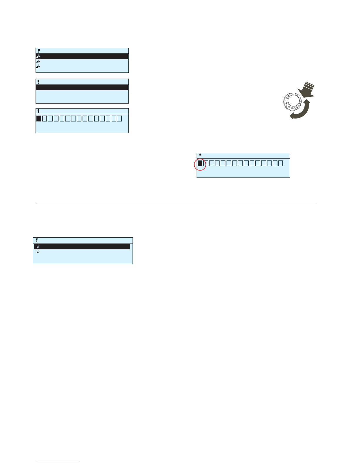
In Ouflex A, alarms are directed to alarm teams. A team may contain up to 5 phone numbers and another team as a backup user.
An alarm is directed to the team that has been defined as its alarm
group’s recipient in the time program in question.
Alarms > Alarm receivers
Alarms > Alarm signal
2.6 Alarm receivers
Turn the control knob.
Press OK to accept a number/sign.
Press OK to move to the next square.
Press Esc to return to the previous square.
Press OK for a number of seconds to accept the number.
Press Esc for a number of seconds to cancel
Deleting the number: Press OK. Rotate the control knob until
in the blank replaces “+” mark and press OK a number of seconds and the number will be eliminated.
Entering the telephone numbers:
OK
2.7 Alarm signal
Alarm signal
OnPois
OFF
Phone number 1
Approve: Press OK for a number of seconds
Cancel: Press ESC for a number of seconds
3 5 8 4 0 8 4 0 0 0 0
Detachable display unit has its own alarm signal. Display alarm signal is
o by default. If display is placed away from the controller, it may be good
to activate alarm signal in display unit.
Page 14
14
Point info -> Wiring info
3.1 Wiring info
Point info
Wiring info >
Bus points >
Time programs >
Wiring info
INPUTS:
U1:UI 1 -10.3 °C >
U2: UI2 23.5 °C >
U3: UI3 Off >
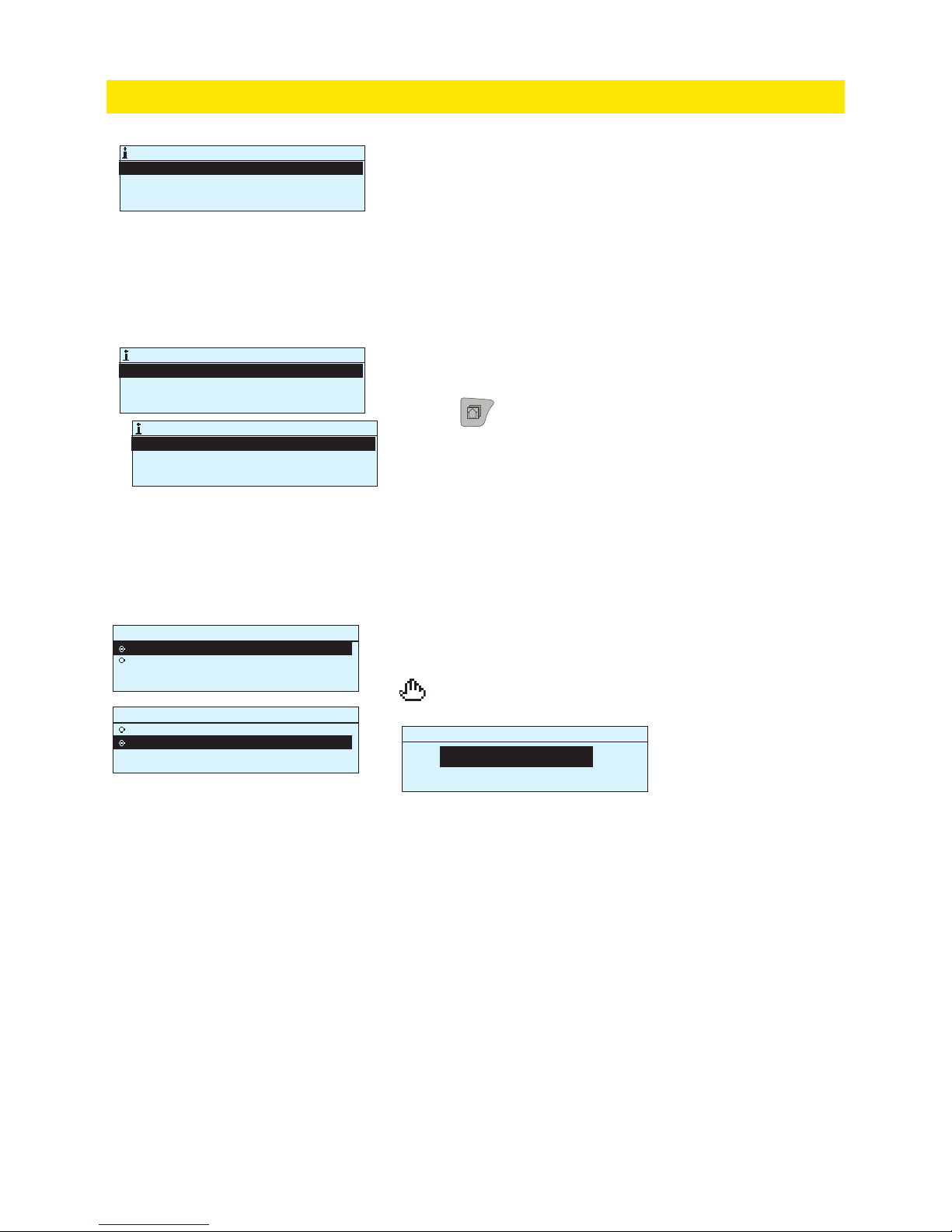
In the point info you can see wiring info, bus points and time programs.
3 Point information
Point information shows all the inputs and outputs of the Ouflex A
device and display names. It also shows the measurement value or
state of the point.
Press -button to see more detailed information, like name
and point ID of the measurement point, You can also rename the
measurement point, change device type and activate trend log.
3.1.1 Measuring point control/manual control
AO1: AO1
Automatic
Manual control
AO1: AO1
Automatic
Manual control
AO1: AO1
0 %
min:0 max:100
Automatic control is the mode that is normally used. If your application allows the change of control mode, you may change automatic control to manual control here.
When you are in the manual control mode, the hand symbol
appears.
UI1: UI1
NameU Outdoor temp. >1:UI
Point ID 2TK1.2TK1. UI2.M.M
Device type NTC10>
Trend log Off >
Page 15
15
Point info -> Bus points
3.2 Bus points
Bus points
Modbus RTU 1 (RJ45) >
Modbus RTU 2 (A1,B1) >
Modbus RTU 3 (A2,B2)
Modbus TCP Master
Modbus RTU 1 (RJ45)
FLEX COMBI 21 >
FLEX UI 12 >
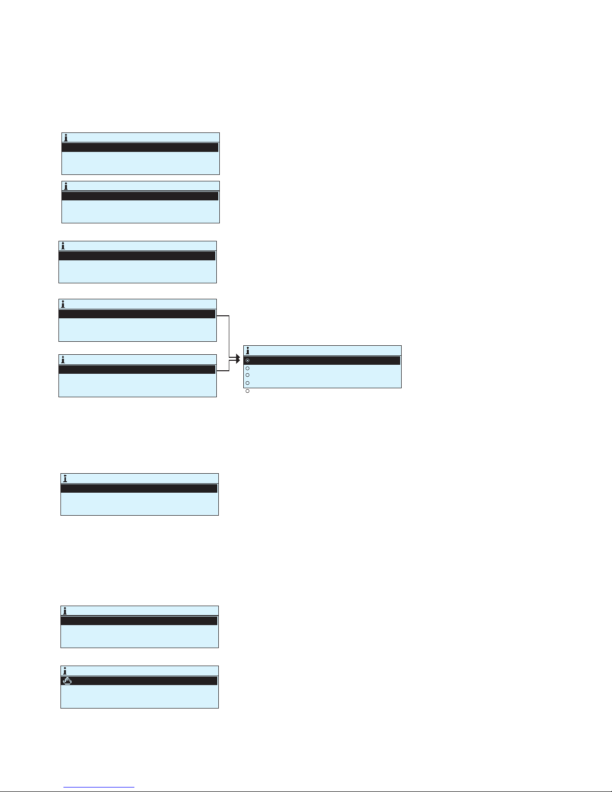
In the bus points menu, you can see those devices which are connected to the bus. By pressing OK in the row of a specific bus device, you will see those points which has been taken into use of the
bus device.
Flex Combi 32
Device information >
Device information
Device state >
Address 1 >
Update device >
IO SW x.x
Device information
Device state >
Address 1 >
Ok messages 0
Timeouts 0
CRC errors 0
Error messages 0
Device state
Active
Passive
Error
Updating
Device type error
Points are grouped by first displaying universal inputs and then analog
and digital outputs. You can change the analog and digital outputs from
automatic to manual control.
You can update the software of Ouman Flex I/O extension device connected to the Modbus RTU bus or change the status of the device. The
device may be active, passive, error, or update mode. You can also read
and change the Modbus address of the device.
Point info -> Time programs
Point info -> Time programs -> Present value
3.3 Time programs
3.3.1 Present value
Time programs
H1 Heating temperature drop Off >
H2 Heating temperature drop Off >
Light control On >
El. group 1 control On >
Heating H1 Temperature drop
Present value Off >
weekly schedule >
Exception schedule >
Special days >
Heating H1 Temperature drop
The present value shows what is the status of the control just now.
When the automatic control is in use, it is shown in the display,
what is state of the control according to the time program at the
moment. Control command can be either a weekly schedule or exception schedule.
When you press the ”Present value” line OK, Ouflex A device asks for a
service code. After entering the service code, you can change the control mode (automatic/ manual). This way you bypass time program and
force the control to the desired mode. When the manual control is in use,
the hand symbol appears on the front of the line.
In Ouflex A, weekly programs can be added to dierent functions
- such as temperature drops, car heating and control of lights. In
your Ouflex A device, you can find time programs under the clock
symbol and/or under the function that a time program has been
made for (e.g. heating control, car heating, control of lights, control of
electric groups, routing of alarms).
Present value Off
Weekly schedule >
Exception schedule >
Special days >
Page 16
16
0 3 6 9 12 15 18 21 24
Time
21:00 Temp. drop
06:00 Delete switch time
00:00 Add new
M T W T F S S
OK
Heating weekly/24-hour program
Monday >
Tuesday >
Wednesday >
Thursday >
Friday >
Saturday >
Sunday >
0 3 6 9 12 15 18 21 24
Time
06:00 Normal temp.
17:00 Temp. drop
00:00 Add new
M T W T F S S
OK
Time State
05:00 On
07:00 Off
00:00 Add new
M T W T F S S
OK
Weekly/24-hour program
Monday >
Tuesday >
Wednesday >
Thursday >
Friday >
Saturday >
Sunday >
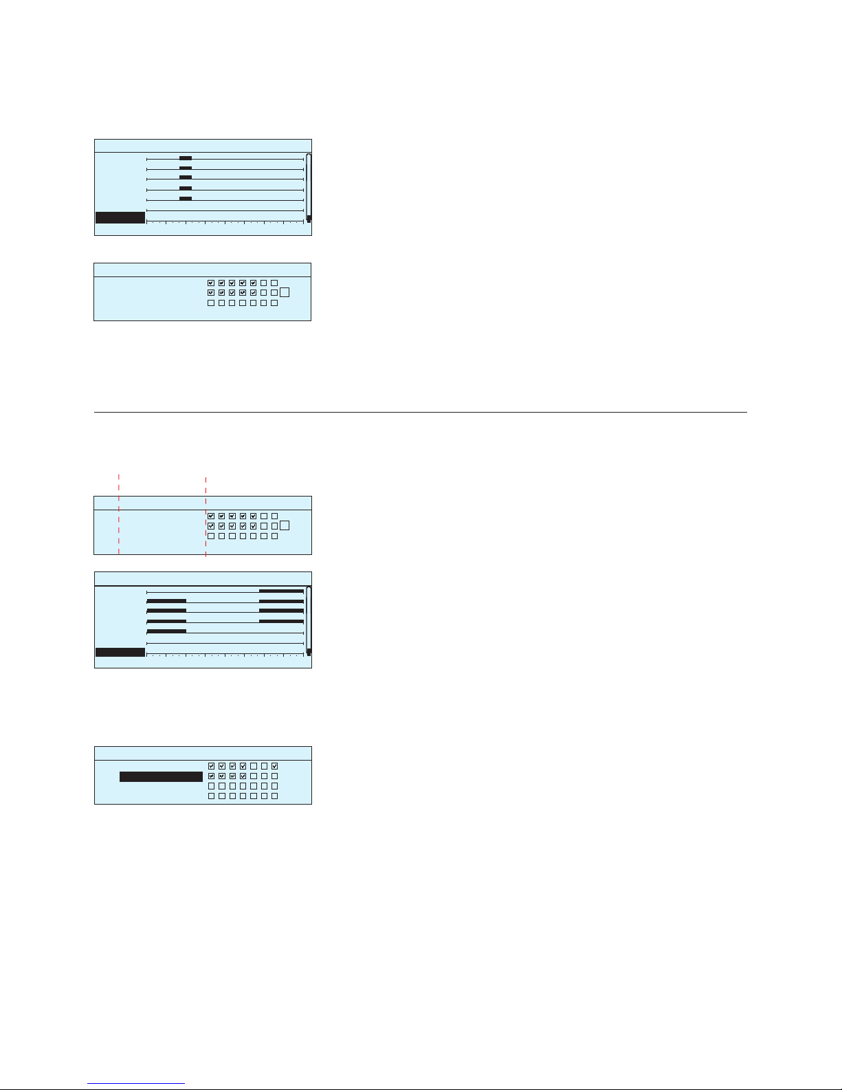
Weekly programs have a general graphic view and an editing view,
where you can see when the control is activated. (e.g., temperature
drop, car heating on, lights on).
Graph
Graph
Editing view
Editing view
Deleting a switch time:
1. Turn the control knob to move to the switch time you wish to delete and press OK.
2. Press OK at control state and select ”Delete switch time”
3. Press OK at the end of the row.
1. Set switch time
2. Set sta te
(=de sired temp. l evel)
3. Sel ect day(s)
In this example, you can see a weekly temperature drop program. Temperature drop is on from 5
pm to 6 am from Monday to Friday.
Browsing a weekly program:
An editing view opens, and it shows all the switch times and also the
states into which the function is driven at these times on the chosen
days.
Turn the control knob to browse a weekly program. If you wish to see
the exact switch times or you wish to change, delete or add switch times, press OK at any weekday.
Adding a new switch time:
1. Press OK at the “Add new” row.
2. Press OK. Set the switch time (set hours and minutes separately).
Press OK to accept.
3. Press OK and then turn the control knob to set the control state (temperature drop weekly program) or ON/OFF state (electric
controls). Press OK to accept.
4. Press OK at each weekday you wish to choose.
5. Press OK at the end of the row to accept the new time program.
Note! Also remember to define when the control returns to automatic (=normal). Press Esc to exit.
Editing a weekly program:
1. Turn the control knob to move to the value you wish to change
and press OK.
2. Turn the control knob to make the time and control mode changes.
Press OK to accept.
3. Press the OK button to change the day of the week.
4. Press Esc to exit.
In this example, you can see a weekly car heating
program. According to the program, car heating is
on from 5 am to 7 am on working days.
Point info -> Time programs -> Weekly schedule
3.3.2 Weekly schedule
Page 17
17
Point info -> Time program > Special days
3.3.3 Special days
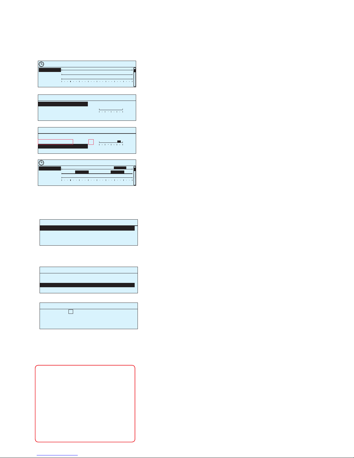
You can enter special day programs as exceptions to normal weekly programs. You can designate a maximum of 7 special day pograms (SD). A special day program is typically created for each
holiday. When the special day program will be applied it is set in
the exception calendar.
Editing view
Graph
Time Mode
Time Mode
00:00 Add new
18:00 On
22:00 Off
00:00 Add newi
Relay 3 Special days
0 3 6 9 12 15 18 21 24
SD 1 >
SD 2 >
SD 3 >
Relay 3 Special days
0 3 6 9 12 15 18 21 24
SD 1 >
SD 2 >
SD 3 >
OK
0 6 12 18 24
0 6 12 18 24
Time program > Exception schedule
3.3.4 Exception schedule
The controls that dier from the normal week schedule will be
done with the exception schedule. The exception schedule is stronger than the week schedule. The date, time and mode to which
control mode will be changed in the period in question are entered
in the exception calendar. To switch from an exception schedule to
weekly schedule mode, select automatic mode.
In the example of relay 3 control has
been done the exception schedule. Relay 3 is switched off (OFF) 21.12.2017
11:30 - 03.01.2018 16:00.
Add/change switch time
Day: 21.12.2017
Time: 11:30
Mode: Off
Repeat: No
Accept: Ready
Date Time
21.12.2017 11:30 Off >
03.01.2018 16:00 Automatic >
00.00.0000 00:00 Add new >
Date Time Mode
00.00.0000 00:00 Add new
Adding a new switch time:
1. Navigate to ”Exception schedule” and press OK.
2. The display will read ”Add new.” Press OK
3. Press OK and set the start date for the program. Press OK
4. Press OK and set the start time for the program. Press OK
5. Press OK and set the mode for the program. Press OK. You can
select from the following:
Deleting a control from the exception schedule:
Select the switch moment to be deleted at mode
“Delete switch time” and select “Ready” to confirm.
Deleting a control from the special day program:
Select the switch moment to be deleted at mode
“Delete switch time” and select “Ready” to confirm.
NOTE! Be sure to set the end time to
the control according to the exception schedule! Set the date and time at
which the control goes to ”Automatic”.
In this case, the control returns back to
the weekly schedule.
Do same kind of selection to ”Repeat”
field as you did at the start time (for
example, if you chose the start time period that repeats monthly, also select
the end time repeats monthly).
Adding a new switch time:
1. Navigate to ”Special days” and press OK.
2. Select an unused special day and press OK.
3. Place the cursor on ”Add new” and press OK. Set the time for the
program (hours and minutes are set separately). Select the control mode to be switched to at the time specified. Accept the program by pressing OK when the cursor is on OK.
4. Navigate to the ”Add new” row. Set the time when the mode will
change from selected mode back to normal mode. Accept the program by pressing OK. You can set several dierent control periods for the same special day.
• one day schedule from the weekly schedule (Monday Sunday)
• a special day from a special day program (SD1 - SD7) or
• one of the following modes: ”on,” ”o” or ”automatic”
If you select a specific day of a week, it means that that
day program is used during the set time period. You can
also make special day programs (SD) in Ounet and take
them into use in the exception calendar.
6. Select, if the exception schedule repeats or not. If you select repeat, it can be repeated every month same time or every year same
time.
7. Accept the exception schedule you created by pressing ”Ready.”
Page 18
18
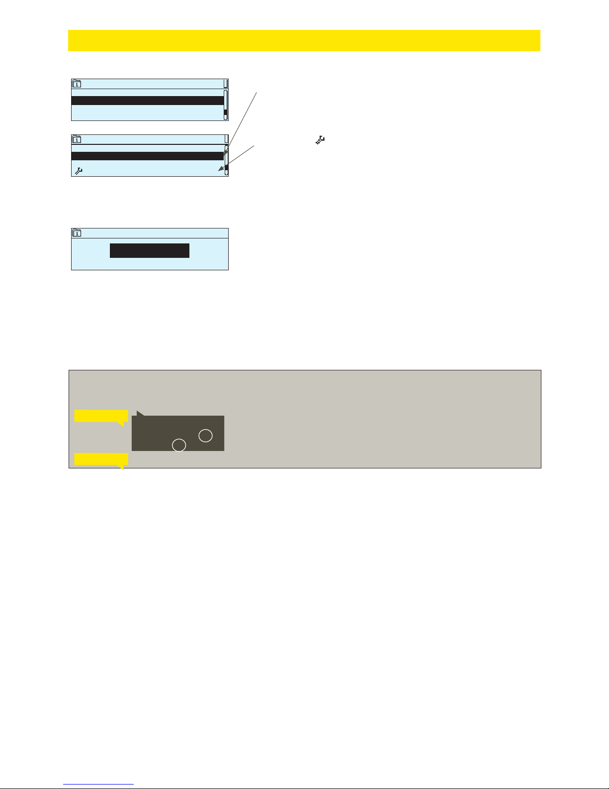
Settings
Supply water min limit 12.0 °C >
Min lmt increase outd. temp. -20 3.0 °C >
Supply water max limit 42.0 °C >
I-control ’s max effect on supp. wtr 2.0 °C >
Asetusarvot
Huonelämpötila 21.0 °C >
Lämmönpudotus ( huonelämpö ) 1.5 °C >
Suuri lämmönpudotus ( huonelämpö ) 5.0 °C >
Menoveden minimiraja 12.0 °C >
Settings
Room temperature 21.0 °C >
Temperature drop (room temperature ) 1.5 °C >
Big temperature drop (room temperature ) 5.0 °C >
Supply water min limit 12.0 °C >
In Ouflex A, settings can be classified into the following categories:
• Main settings
• Hidden settings
You can hide/show these settings by pressing OK for a few seconds. When visible, these settings are shown slightly indented.
• Settings that require maintenance code
There is a symbol in front of these settings. If you try to change
one of these settings, your Ouflex A device asks you to enter the
maintenance code.
Changing a setting:
Choose the desired setting by turning the control knob. Press OK to go
to the view where editing is possible. Change the setting.
Press OK to accept the change.
Press Esc to exit the editing view.
You can see the setting range (minimum and maximum value), if there
is one, in the editing view.
Locking the settings:
Lock the settings to prevent unauthorized persons from changing them.
The device will then ask for lock code before it let’s you change the settings. You can lock the settings in Ouflex A device system settings.
Huonelämpötila
21.0°C
min: 0.0 max: 95.0
Room temperature
21.0°C
min: 0.0 max: 95.0
4 Settings
If a GSM modem is connected to Ouflex A device and the setting values have been brought into SMS interface, you can edit settings by text message. Send a message “Key words”. The reply message shows you which key words are in use in the
application. The example below describes the communication principle.
Send a message: H1 Settings.
The controller sends the main settings to your mobile phone. Editing the setting
values: write the new setting in place of the old setting and send a message
back to the controller. The controller sends the setting as a return message.
H1 SETTINGS
H2 SETTINGS
H1 Settings:
Room temperature = 21.5°C/
Temp.drop = 3.0°C/
Page 19
19
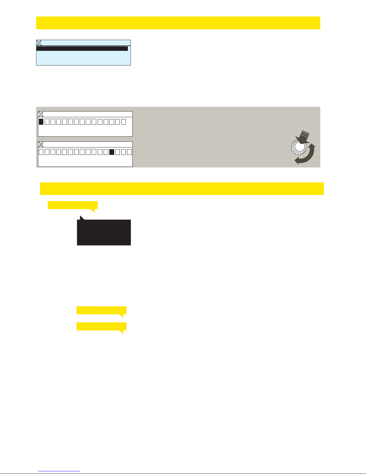
There may be fields that you can rename in your Ouflex device. You
often download an application where general names have been given to the controls, and you may want to rename them more accurately.
In heating control, for example, the rooms have typically been named
”Room 1”, ” Room 2”, etc. You may want to give them more accurate
names. In control of electric groups, you may want to rename ”Electric
group 1” and ”Electric group 2” more accurately, depending on what
you actually control with the relay in question.
Room selection
Name of room 1 Room 1 >
Name of room 2 Room 2 >
Move to the title you wish to rename and press OK. A naming view
opens. Turn the control knob and accept each letter by pressing OK.
Move to the next square by pressing OK.
Return to the previous square by pressing ESC.
Accept the name by pressing OK for a number of seconds.
Cancel by pressing ESC for a number of seconds.
Huone 1 nimi
Hyväksy: paina pitkään OK:ta
Peruuta: Paina pitkään ESC:iä
H u o n e 1
Huone 1 nimi
Hyväksy: paina pitkään OK:ta
Peruuta: Paina pitkään ESC:iä
A s u n t o 1 A
Name of room 1
Approve: Press OK for a number of seconds
Cancel: Press ESC for a number of seconds
R o
o
m
1
Approve: Press OK for a number of seconds
Cancel: Press ESC for a number of seconds
Apa r t m e n t
1 A
Name of room 1
5 Naming
OK
You can send the text message question mark to the controller to get a list of
key words. If the controller has a device ID in use, always write the device ID
in front of the key word (example. Ou01 KEY WORDS or Ou01 ?). Capital and
small letters are dierent characters in the device ID!
The controller sends as a text message a list of keywords, that can be used to
get information about the controller functions. Key words are separated by
a /. You can write the key word using capital or small letters. Write only one
key word/message. Store the key words into your phone’s memory.
Send the following text message to the controller: KEY WORDS.
If a GSM modem is connected to the Ouflex you can communicate with the
controller by text message using key words.
6 Communication via a mobile phone
The reply message will show all active alarms.
The reply message will show information about the latest alarms.
Informative messages
Change of the setting value by text message
Change of the selection by text message
Informative messages can not be edited or sent back to the Ouflex A.
Informative messages are, for example. measurements, dierent types
of information displayed, or the alarm queries
Key words:
Active alarms
Alarm history
KEY WORDS
ACTIVE ALARMS
ALARM HISTORY
Send a message with the correct key word.
The controller sends the settings to your mobile phone. Editing the setting values:
write the new setting in place of the old setting and send a message
back to the controller. The controller sends the setting as a return message.
Send a message with the correct key word.
The controller sends a return message in which a * appears in front of the control
mode in use. If you want to change the control mode, move the * in front of the
desired control mode and send the message back to the controller. The controller
will then send a return message showing that it has switched to the desired control
mode.
Page 20
20
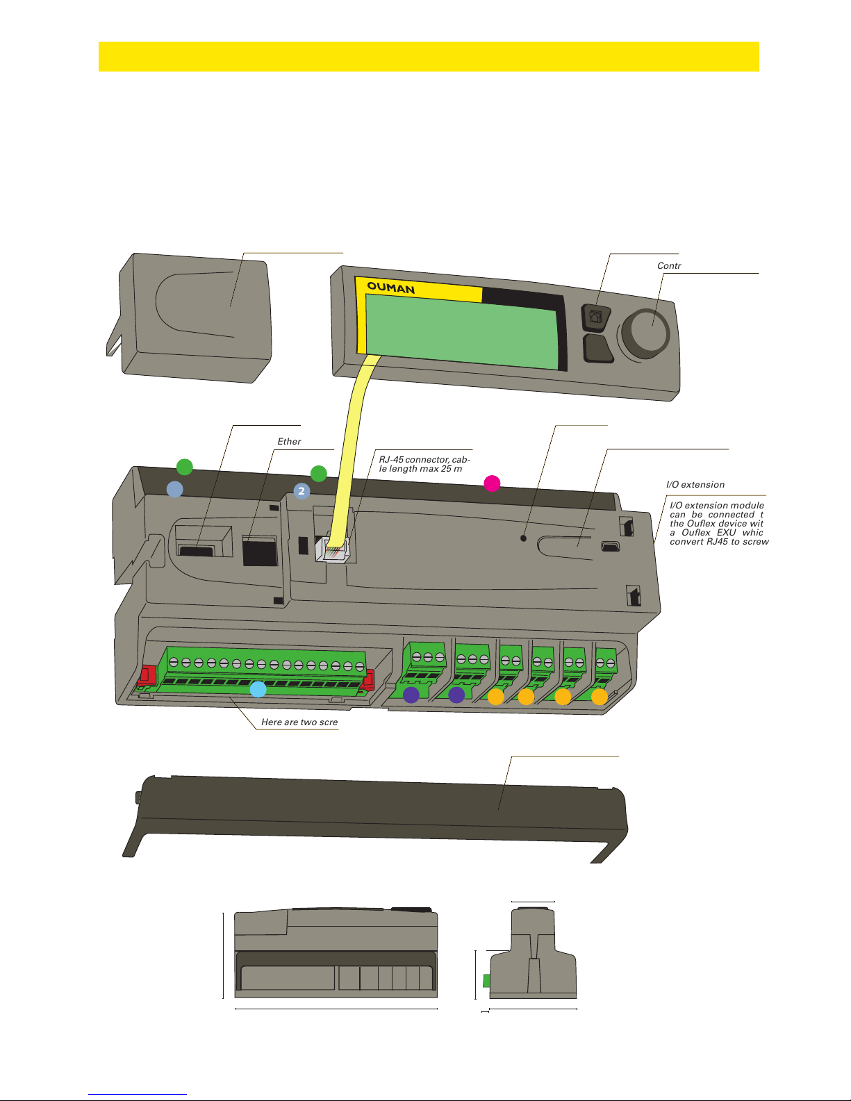
7 Ouflex A device I/O connections and structure
Ouex A is a freely programmable and DIN-rail-attachable building automation system for
control and monitoring. The DIN-standard-compatible structure of the Ouex A device enables installation to most common cabinets. Detachable strip connectors make installation easier.
Control knob and OK button
Info button
Detachable connector shield
Detachable strip connector shield
Acknowledge alarm button
Alarm led
Display connector
RJ-4 5 connector, cab -
le length max 25 m
USB host connector
Ethernet connector
Dimensions:
I/O extension modules
can be connected to
the Ouex device with
a Ouex EXU which
convert RJ45 to screw
terminal .
I/O extension connector
Here are two screw ternimals Modbus RTU lines
93,3
213,5
50
90
45
17
ESC
55
2
2
4
666
1
3
1
6
OK
OUFLEX A
6,8
Page 21
21
4
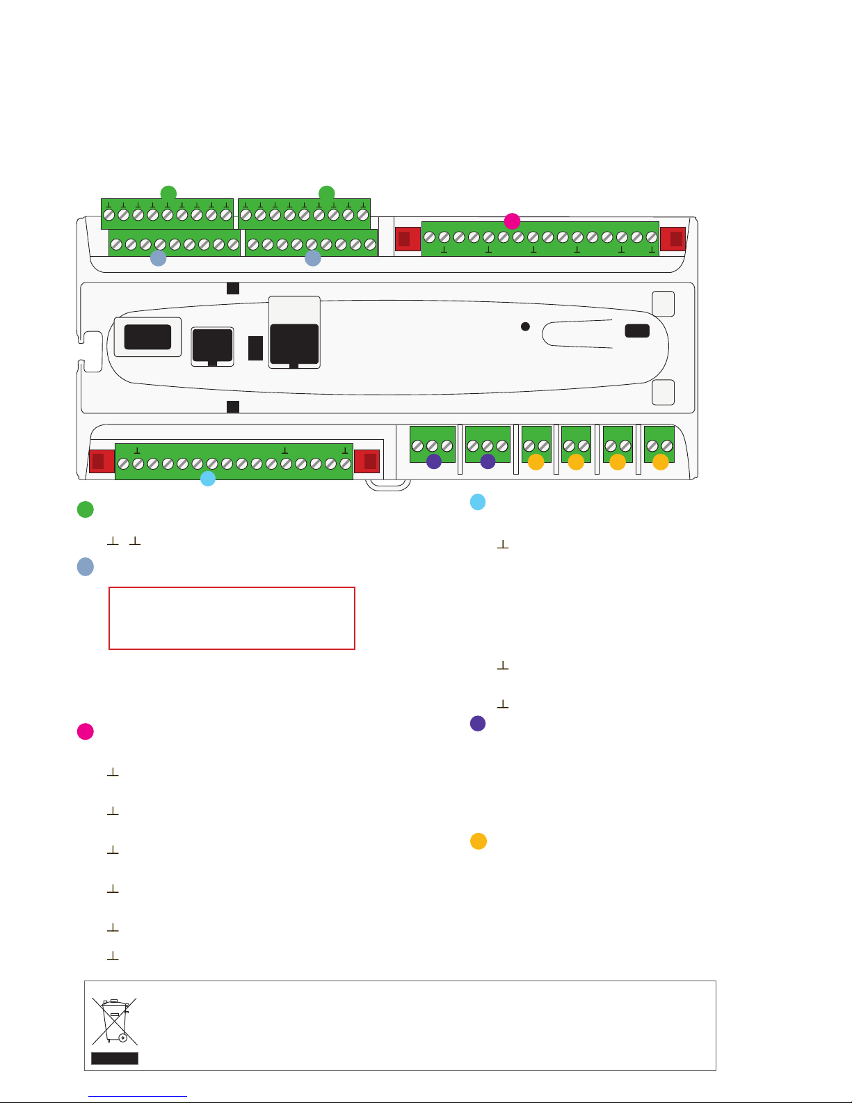
Detachable strip connectors (power supply, battery
backup, RS-4 85 bus connections, outputs)
Connector markings:
91 24 Vac power supply
GND
92 12 Vdc backup voltage input
BG RS-4 85 bus isolated ground
A1 and B1 RS- 485 bus connection
A2 and B2 RS- 485 bus connection
42 and 43 24 Vac output (Triac or continuous 24 Vac)
61 0…10 V output
GND
44 and 45 24 Vac output (Triac or continuous 24 Vac)
62 0…10 V output
GND
5
Detachable strip connectors
(Change -over contact relays max 230 Vac, 6 A )
Connector markings:
71 Relay 1 NO
72 Relay 1 C
73 Relay 1 NC
74 Relay 2 NO
75 Relay 2 C
76 Relay 2 NC
6
Detachable strip connectors
(relays with normally open contact max 230 Vac, 6 A)
Connector markings:
77 Relay 3 NO
78 Relay 3 C
79 Relay 4 NO
80 Relay 4 C
81 Relay 5 NO
82 Relay 5 C
83 Relay 6 NO
84 Relay 6 C
3
Detachable strip connector
(operation voltage and outputs)
Connector markings:
41 24 Vac operating voltage output
GND
63 0…10 V output
41 24 Vac operating voltage output
GND
64 0…10 V output
41 24 Vac operating voltage output
GND
65 0…10 V output
41 24 Vac operating voltage output
GND
66 0…10 V output
41 24 Vac operating voltage output
GND
93 15 Vdc operating voltage output
GND
Detachable strip connectors
(universal measurement, digital and pulse counter inputs)
Connector markings:
1…12 Universal input
13…16 Universal input,
pulse counter input
21...22 Digital input,
pulse counter input
2
Detachable strip connectors
(measurements’ ground)
Connector labels
… Measurements’ ground (16pcs)
1
71 72 73 74 75 76 77 78 79 80 81 82 83 84
1 2 3 4 5 6 7 8 9
10 11 12 13 14 15 16 21 22
41 41 41 41 4163 64 65 66 93
4
5 5
6 6 6 6
3
2 2
1 1
91 92 BG A1 B1 A2 B2 42 43 61 44 45 62
Ouex A includes 34 I/O-points, and also versatile data transfer and eld bus connections. In addition, the device contains 24 Vac and 15 Vdc outputs. Display unit is detachable, and can be relocated.
It is possible to increase the number of I/O-points with external I/O-modules via bus connections.
The enclosed marking on the additional material of the product indicates that this product must not be disposed of together with household waste at the end of its life span. The product must be processed separately from other waste to prevent
damage caused by uncontrolled waste disposal to the environment and the health of fellow human beings. The users must
contact the retailer responsible for having sold the product, the supplier or a local environmental authority, who will provide additional information on safe recycling opportunities of the product. This product must not be disposed of together with
other commercial waste.
Product disposal:
Universal inputs are configured NTC-10 measurements by default. Do not connect transmitter outputs over 5 V if measurement channels are not
configured to transmitter measurements.
Page 22
22
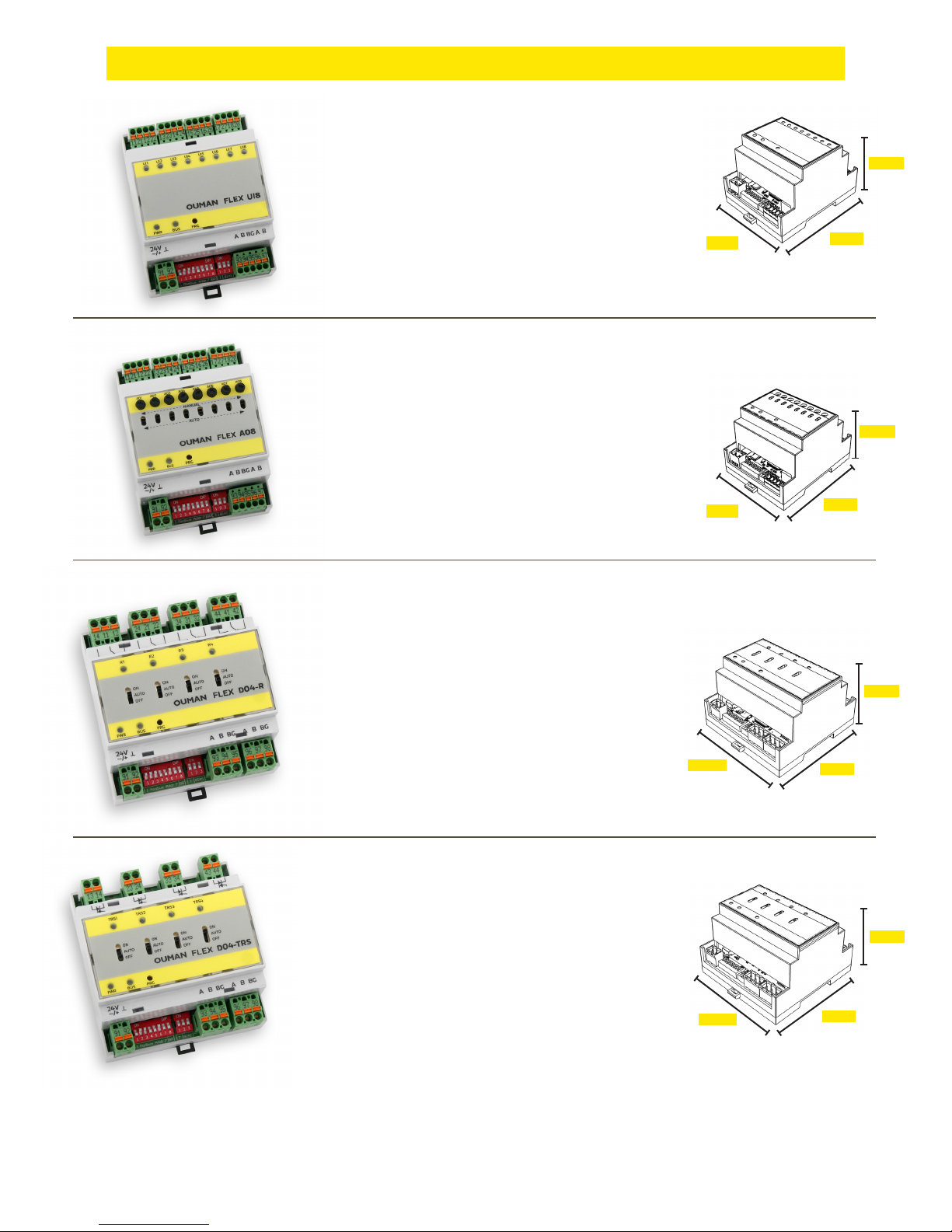
Extension units
Extension units
FLEX DO4-TRS module consists of 4 triac outputs
• Each triac control has 3 stage switch for selection between automatic control, forced ON or OFF
(AUTO-ON-OFF).
• 24…230Vac, max 1A/output
• Potential-free AC switch
• DC controls require a supplementary relay in
installaion
88 mm
(5M)
94 mm
88 mm
(5M)
94 mm
71 mm
(4M)
71 mm
(4M)
59 mm
64 mm
91 mm
91 mm
59 mm
59 mm
FLEX UI8 device has 8 universal inputs.
Supported signals and sensor types are:
• transmitters 0-10V
• transmitters 0/4-20mA
• digital contact input
• potential free pulse counter
• first supported passive sensors:
- NTC10, NTC1.8, NTC2.2 and NTC20
- Ni 1000 LG, Ni 1000 DIN 43760
- Pt 1000
FLEX AO8 has 8 analog outputs.
• Output voltage range 0-10 V
• Output current 7 mA/output
• Each output has Auto-Manual switch.
• In manual mode the output voltage of each channel
is adjusted via potentiometer
FLEX DO4-R relay module consists of 4 changeover contact relays.
• Each relay control has 3 stage switch for selection
between automatic control, forced ON or OFF
(ON-AUTO-OFF).
• Change-over contact relay 230 Vac/ 4A or
24Vdc/4A
• Easy to install in electrical cabinet
FLEX UI8
FLEX AO8
FLEX DO4-R
FLEX DO4-TRS
Page 23
23
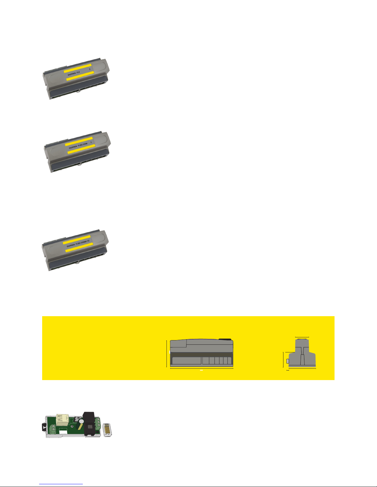
Flex UI 16 is a DIN-rail-attachable and RS-485-connected universal I/O
extension unit. It has on 16 universal measurement inputs (UI) that
can read the following types of data:
- Passive sensors
- Transmitters
- Digital inputs
- Pulse information 4pcs. (inputs 13...16)
Flex Combi 21 is a DIN-rail-attachable and RS-485-connected universal I/O extension unit. It has 21 I/O points.
The device has:
9 pcs. universal measurement inputs (UI) that can read:
- Passive sensors
- Transmitters
- Digital inputs
- Pulse information
2 pcs. 0…10 V universal outputs (AO)
2 pcs. relay outputs with change-over contact
4 pcs. relay outputs with normally open contact
4 pcs. 24 Vac Triac outputs
Flex Combi 32 is a DIN-rail-attachable and RS-485-connected universal I/O extension unit. It has 31 pcs I/O points, and 5 pcs 24Vac outputs and 15Vdc output.
The device has:
16 pcs. universal measurement inputs (UI) that can read:
- Passive sensors
- Transmitters
- Digital inputs
- Pulse information 4 pcs. (inputs 13...16)
6 pcs. 0…10 V universal outputs (AO)
2 pcs. relay outputs with change-over contact
4 pcs. relay outputs with normally open contact
4 pcs. 24 Vac Triac outputs
Interface card for modem and local I/O extension
- unisolated RS-485 bus, supported protocols Modbus-RTU
- USB host connection (not in use)
- 15 Vdc voltage output, max 750 mA (total capacity together with
the Ouflex A device 15 Vdc voltage output (strip connector 93)
FLEX COMBI 32
FLEX COMBI 21
FLEX EXU
FLEX COMBI 32, FLECX COMBI 21and FLEX UI116 dimensions (mm)
93,3
213,5
50
90
45
6,8
21
FLEX UI16
UI16
Page 24
24
OUFLEX
We reserve the right to make changes to our products without a special notice.
XM1102_Ouflex A _User manual_v.2.5.0_ENG_ 20180911
Freely programmable automation system
Saving energy, creating comfort
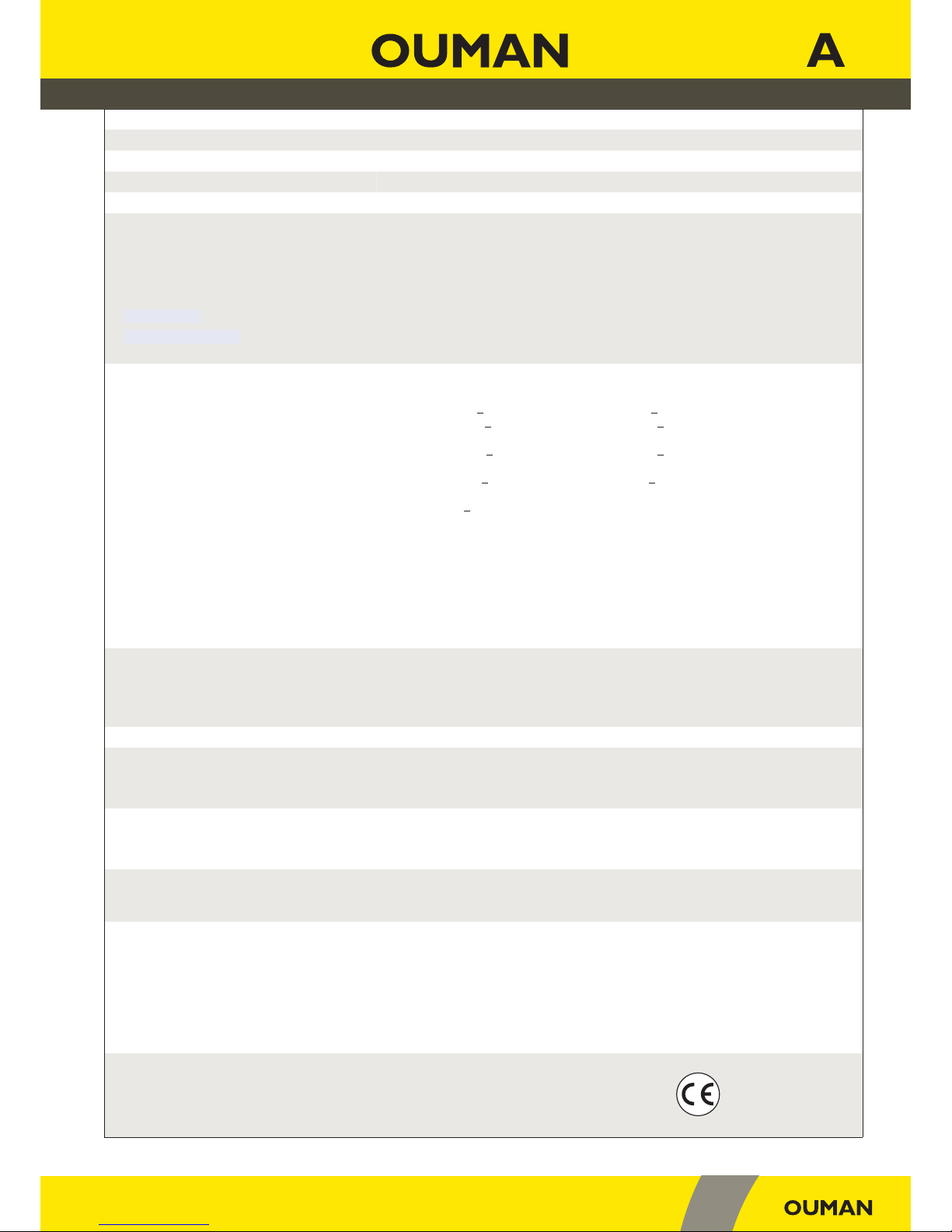
Dimensions width 213,5 mm, height 93,3 mm, depth 96,8 mm
Weight 0.7 kg
Protection class IP 20
Operating temperature 0 ºC…+40 ºC
Storing temperature -20 ºC…+70 ºC
Power supply
Operating voltage 24 Vac, 50 Hz (22 Vac - 33 Vac)
Power required
(15 Vdc output =if not connected) 13 VA
(15 Vdc output = 750 mA) 34 VA
Notice! Please consider 24 Vac operating voltage and power required for Triac outputs.
Backup input 12 Vdc
Current consumption 300mA / 3,6W (relays not in use)
400mA / 4,8W (relays in use)
Universal measurement input (can be configured) measurement types:
Passive sensors (inputs 1…16) Measurement channel accuracy:
- NTC10 element: +0,1 ºC between -50 ºC…+100 ºC, +0,25 ºC between +100 ºC…+130 ºC
- NTC 1.8 element: +0,2 ºC between -20 ºC…+40 ºC, +0,6 ºC between +40 ºC…+70 ºC and
+2.0 temperatures above 75 °C.
- NTC 2.2 element: +0,2 ºC between -20 ºC…+55 ºC, +0,5 ºC between +60 ºC…+70 ºC and
+2.0 temperatures above 75 °C.
- NTC20 element: +0,1 ºC between -20 ºC…+70 ºC, +0,6 ºC between +75 ºC…+120 ºC
- Ni1000: +1,0 ºC between -50 ºC…+130 ºC
- Ni1000 DIN: +0.2 ºC between 0 ºC…+130 ºC, +0.5 ºC between -5 ºC…+120 ºC
- PT1000 element: +1,0 ºC between -50 ºC…+130 ºC
Also sensor tolerances and the eect of cables must be considered when calculating
total accuracy. .
Active sensors (inputs 1…16)
0…10 V voltage message, meas. accuracy 1 mV
Milliampere signal with shunt resistor 0/4-20 mA
Contact information (inputs 1…16) Contact voltage 5 Vdc. Contact current 0,5 mA
Contact resistance max 1,9 kΩ (closed), min 11 kΩ (open)
Counter inputs (inputs 13…16)
Minimum pulse length 30 ms
Digital input measurement types:
Contact information (inputs 21 and 22) Contact voltage 15 Vdc. Contact current 1,5 mA
Contact resistance max 500 Ω (closed), min 1,6 kΩ (open)
Counter inputs (inputs 21…22)
Minimum pulse length 30 ms
Analog outputs (61...66) Output voltage range 0…10 V. Output current max 10 mA/output.
Relay output
Change-over contact relay (71…76)
Normally open contact relay ( 7 7…8 4)
2 pcs, 230 V, 6 A
4 pcs, 230 V, 6 A
Triac outputs
24 Vac (42 and 43)
24 Vac (44 and 45)
Output current together max 1 A
Output current together max 1 A
Operating voltage outputs
5 pcs 24 Vac outputs (41)
15 Vdc output
Output current max 1 A /output
Output current max 750 mA
Data transfer connections
RS-485 bus (A1 and B1)
RS-485 bus (A2 and B2)
USB-host connection
USB-device connection
Ethernet
Ouman Access
Galvanically isolated, supported protocols Modbus-RTU
Galvanically isolated, supported protocols Modbus-RTU
RS-232-modem, Ouman GSM-modeemi
Full-duplex 10/100 Mbit/s, supported protocols Modbus-TCP/IP
Intelligent remote connection built-in for use with Ounet and Ouflex BA Tool
APPROVALS
EMC-directive 2014/30/EU
Interference tolerance EN 61000-6-1
Interference emissions EN 61000-6-3
 Loading...