


OUMAN EH-201/L
is a new generation
heating regulator. Its versatility, intelligence
and clarity have made it an ideal heating
regulator for all kinds of water circulation
heating systems.
In addition to heating regulation, EH-201/L has
a number of other control and alarm functions
of buildings’ technical systems.
Measurement information can be read, settings
and controls can be checked and adjusted, and
alarms can be received and acknowledged via
a GSM telephone’s text messages.
EH-203 gives its user instructions
on a display.
Types of heating systems:
Radiator heating
Floor heating
Air conditioning
preregulation
Types of heating production:
District heating exchangers
Boiler plants
Accumulators
District heating substations
Locations:
Apartment buildings and row houses
Business premises and office buildings
Private homes and summer cabins
User manual
EH-201/L
Heating
regulator
MODBUS

Use the button to m
circuit (HW). Press
the or button t
o
Exit with
Press
OK.
-+
ESC.
Changing the heating regulat
OK.
ESC.
Press the button to move th
change. Press
the or button to ch
Exit with
Press -+
Press the button to move c
HW Settings
°C
Dom.hot
H1 Select
Heating curve
Settings
Measurements
H1 Settings
Room temp.
Temp drop(w)
Min. limit
Max. limit
Room compens.
Wind compens.
Sun compens.
Pre-increase
Autumn dry
21.5
15
70
4
0
2
0
0
0
Changing the domestic hot w
OUMAN EH-201/L FOR STARTERSOUMAN EH-201/L
Congratulations on your excellent choice! You have
arquired a diverse new generation heating regulator
designed for residental and office buildings - most a
top - of - the - line product which can be adapted to the
most diverse locations and heating systems.
Next we will introduce the regulator and the basic
principles for using the user manual.
User panel
Regulating circuit code
Browse button
Group select button
indicates that this is one
circuit heating regulator.
- moves the
> cursor up and down.
not in use in Ouman
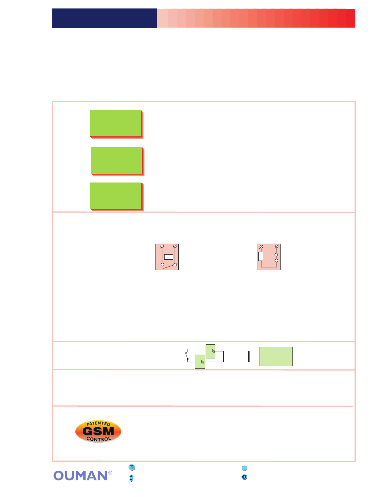
EH-201/L
The example shows the regulating
circuit's operating mode.
Regulator opens the 3-point
controlled actuator.
Regulator closes the 3-point
controlled actuator.
Height up the pillar shows
the position of he voltage
controlled actuator.
Valve is fully open (100%)
and the control voltage is 10 V.
Valve is fully closed (0%) and
the control voltage is 0 V or
2 V (2 ... 10 V actuator).
Decrease
button
INFO-button -gives
operating instructions and
additional information on
the display in different situations.
ESC press to
return to the
previous display
HINT! When you press + button in adjoining basic display
mode, the regulator displays all the measurement results in
turn and then returns to the basic display mode.
Symbols which indicate
actuator control mode.
Increase -button
OK
button
H1 Automatic
Outdoor -15°C
SupplyTemp52°C
>Selection
ESC- press to return to the previous display
Reading the page:
Rate from the basic
display to the topic
of the page.
The colored section
presents the actual topic.
Additional information
about the topic
in question.
Settings that can be changed are
marked on the page in .white
OUMAN EH-203OUMAN EH-203OUMAN EH-201/LOUMAN EH-201/L
Ajan asetus
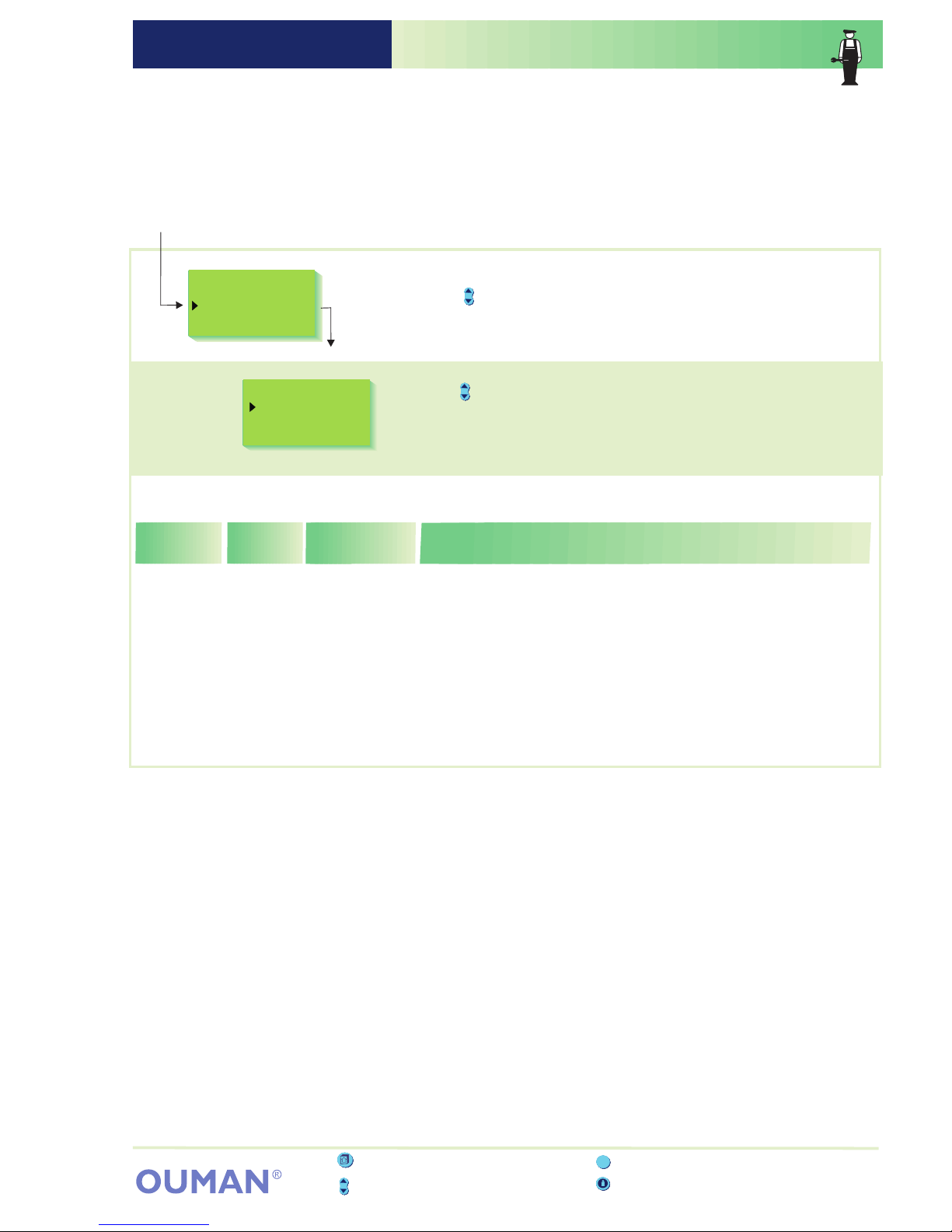
In Ouman EH-201/L the regulator is controlled by many different
settings. By browsing you can see which settings you have in use.
Browsing and setting changes occur in the following way:
Changing the heating regulating circuit setting:
OK.
OK.
ESC.
Press the button to move the cursor to the setting that you want to
change. Press
Press the or button to change the setting. Press
Exit with
-+
Press the button to move cursor to "Settings". Press OK.
SETTINGS Browsing, making changes
6
H1 Select
Heating curve
Settings
Measurements
H1 Settings
Room temp.
Temp drop(w)
Min. limit
Max. limit
Room compens.
Wind compens.
Sun compens.
Pre-increase
Autumn dry
Valve close
GeothHeatAcc
21.5
5
15
70
0
2
25
0
0
55
4
Infobutton - gives operating instructions
Browsebutton - moves the cursor up and down
ESC
Press ESC until the display no longer changes.
Youare then in the "Selection" display shown in the adjoining picture.
OPERATINGINSTRUCTION:
Press OK.
Groupselect button - not in use in EH201/L
H1
Outdoor °C
SupplyTemp °C
Selection
Automatic
-15
52
Explanation:
Room temperature setting, which user has
set.
The supply water temperature drop,
determined by the clock program or the
external home/away switch. (Room
compensation takes a desired drop in room
temperature into account)
Minimum allowed supply water temperature.
Maximum allowed supply water
temperature.
Room compensation ratio: If the room
temperature is different than what it is set at,
the room compensation corrects the supply
water temperature.
(Eg.) If the room compensation is 4 and the
room temperature has risen 1,5 °C above
the setting, the regulator drops the supply
water temperature 6 °C (4x1,5 °C =6 °C).
Wind compensation ratio: Ahouse cools
down in windy weather. In that case the
wind compensation raises the supply water
temperature. The reading indicates the
maximum amount that the wind compens.
can raise the supply water temperature.
Range:
5.0...45.0°C
0...35°C
5...95°C
15...125°C
0...7°C
0...7°C
Factory
settings:
21.5°C
0°C
15°C
70°C
4°C
0°C
Settings:
Room temp.
Temp drop
Min. limit
Max. limit
Room compens.
Wind compens.
(w)
(supply water)
Attention!
During temp. drop period
regulator use the calculated
room temp. setting, which is
INFORMATIONABOUT SETTINGS:
80
65
50
35
20
200-20 °C
Minimum limit
80
65
50
35
20
200-20 °C
Maximum limit
Room sensor (TMR) must
be connected (Meas.3 or
LON bus).
Room temp. -
Temp drop(w)
Room compens.
Condensed guide
for the buttons.
EH 201/L

OUMAN EH-201/L CONTENTS Version 1.49OUMAN EH-201/L
Maintenance guide
User guide
Page
These pages contain
directions for maintenance
persons authorized by
Ouman. Access to the
regulator's maintenance
mode is prevented by a
maintenance mode.
Special maintenance
Settings for characteristic heating curve
Settings
Measurements. labelling
Measurements and sensor connection information
Supply water temperature information
Operating modes
Clock functions
Language selection
Type information
Start function
Alarms
Entering the maintenance mode
Tuning values
Settings
Trends
Actuator selection
Relay 1 control selection
Relay 2 control selection
Restore factory settings
Settings
Measurement 6 setting
Wind/ Sun measurement
Digital inputs 1 and 2
LON initialization
Buss measurements
Text message connection via the modem
Text message connection via the buss
GSM functions
Direct data connection to computer (monitor application)
4
6
9
10
11
12
13
16
17
18
19
20
21
22
23
24
25
26
28
29
30
31
32
33
35
36
37
38
39
Ouman
Oy
Voimatie 6, FIN-90440 Kempele Finland
Tel.+358 424 8401
ouman.fi
40
41
42
43
44
Installation and maintenance guide
Connection guide
Optional equipment
Index
Technical information

The basis for an even room temperature is a characteristic
heating curve of just the right shape. The right shape for a
characteristic heating curve depends on many factors.
In Ouman EH-201/L the characteristic heating curve can be
adapted to exactly meet the needs of the facility from three
points;
EH-201/L prevents the setting of an ncorrectly shaped
characteristic heating curve. It automatically suggests an
adjustment.
1. outdoor temperature of -20 C
2. outdoor temperature of 0 C
3. outdoor temperature of +20 C
o
o
o
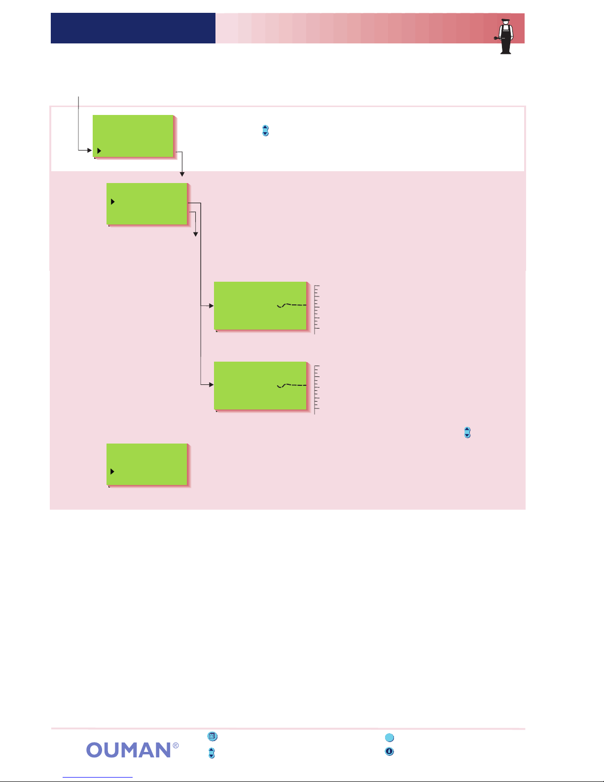
Press
Press the or button to set the supply water temperature at an
outdoor temperature of -20 C.
o
Press
OK.
OK.
-+
Press ESC until the display no longer changes.
You are then in the "Selection" display shown in the adjoining picture.
Press the button to move cursor to "Heating curve"
Press
OK.
OUMAN EH-201/L SETTINGS FOR HEATING CURVEOUMAN EH-201/L
OPERATING INSTRUCTION:
80
65
50
35
20
20 0 -20 °C
80
65
50
35
20
20 0 -20 °C
80
65
50
35
20
20 0 -20 °C
Press OK.
H1
Outdoor °C
SupplyTemp °C
Selection
Automatic
-15
52
H1 Curve:
-20 = °C
20 = 18°C
0 = 41°C
+
58
H1 Curve:
-20 = 58°C
20 = 18°C
0= °C
+
41
H1 Curve:
-20 = 58°C
0 = 41°C
+20 = °C18
CURVE INTERPRETATION:
When the outdoor temp. is:
-20 C, the supply water is +58 C
0 C, the supply water is +41 C
+20 C, the supply water is +18 C
The temperature of the supply water may vary from the curve
if a reduced operation mode, room, wind or sun compensation
has been connected to the regulator or if one of the limiting functions
limits the temperature (see p. 10).
If the outdoor sensor is disconnected or if the sensor is broken,
the regulator assumes that the outdoo temperature is 0 C (use during
construction without the outdoor sensor).
oo
oo
oo
o
Attention!
80
65
50
35
20
20 0 -20 °C
H1 Curve:
-20 = 58°C
0 = 41°C
+20 = 18°C
Supply water
temperature
Outdoor temperature
4
ESC - press to return to the previous display
Group select button - not in use in EH-201/L
Info button - gives operating instructions
Browse button - moves the cursor up and down
ESC
1
2
3
H1 Select
Heating curve
Settings
Measurements
Info water temp
Operat. modes
Clock functions
Language/Keel
Type info
Start function
Mainten. mode
Press
Press the or button to set the supply water temperature at an
outdoor temperature of 0 C.
o
Press
OK.
OK.
-+
Press
Press the or button to set the supply water temperature at an
outdoor temperature of -20 C.
Exit with
o
Press
OK.
OK.
-+
ESC.

OUMAN EH-201/L Instructions for setting the curveOUMAN EH-201/L
80
65
50
35
20
20 0 -20 °C
EXAMPLES OF DIFFERENT HEATING SYSTEMS:
B) Floor heating
C) Preheating for air conditioning
If the room temperature drops in subzero weather, raise the curve setting at -20 C.
If the room temperature rises in subzero weather, lower the curve setting at -20 C.
If the room temp. feels chilly at zero degree weather, raise the curve setting at 0 C.
In this way you can set the regulating curve to meet the heating needs of your facility.
o
o
o
INSTRUCTION:
a) Normal radiator network
(factory setting)
80
65
50
35
20
20 0 -20 °C
80
65
50
35
20
20 0 -20 °C
H1 Curve:
0 = 44°C
+
-20 = 62°C
20 = 21°C
H1 Curve:
0 = 41°C
+
-20 = 58°C
20 = 18°C
H1 Curve:
0 = 27°C
+
-20 = 32°C
20 = 21°C
5
HOUSES WITH FLOOR HEATING:
Set the EH-201/L regulator's maximum limit between +35 ... +40 C and
the minimum limit between +20 ... +25 C.
In floor heating solutions it is important to make sure that exessively
hot water which could damage structures or surfaces doesn't ever get
into the network. A mechanical thermostat should be installed on a
supply water pipe which stops the circulation pump in case of
overheating. Ouman Oy keeps CO1A surface mounted thermostats in
stock that are suitable for this purpose. Set the thermostat at
40 ... 45 C.
o
o
o
Surface mounted
thermostat CO1A
AC 230V 15 (2,5) A
21 4
Pump
control
230 VAC
Pump control
Surface mounted thermostat’s C01A connection:
Model Set point Differential range Temp. of cover,range °C °C
o
C
CO1A +20...+90 8 -35...+120
ATTENTION!
Wait a sufficient amount of time after the adjustment so the change has time to effect
the room temperature.
ESC - press to return to the previous display
Info button - gives operating instructions
Browse button - moves the cursor up and down
ESC
Group select button - not in use in EH201/L
HEATING CURVE
H1 Curve:
(-20= ;
0= ;
+20= )
58
41
19
KEYWORD:
Heating curve

OUMAN EH-203OUMAN EH-203OUMAN EH-201/LOUMAN EH-201/L
Ajan asetus
Changing the heating regulating c ircuit setting:
OK.
OK.
ESC.
Press the button to move the cursor to the setting that you want to
change. Press
the or button to change the setting. Press
Exit with
Press -+
Press the button to mov e cursor to "Settings". Press OK.
SETTINGS Browsing, making changes
6
H1 Select
Heating curve
Settings
Measurements
H1 Settings
Room temp.
Temp drop(w)
Min. limit
Max. limit
RoomCompens
Pre-increase
Autumn dry
Valve close
21.5
5
15
70
0
2
19
4.0
ESC - press to return to the previous display
Info button - gives operating instructions
Browse button - moves the cursor up and down
ESC
Press ESC until the display no longer changes.
You are then in the "Selection" display shown in the adjoining picture.
OPERATING INSTRUCTION:
Press
OK.
Group select button - not in use in EH201/L
H1
Outdoor °C
SupplyTemp °C
Selection
Automatic
-15
52
Explanation:
Room temperature setting, which user has
set.
The supply water temperature drop,
determined by the clock program or the
external home / away switch. (Room
compensation takes a desired drop in
room temperature into account)
Minimum allowed supply water temperature.
Maximum allowed supply water
temperature.
Room compensation ratio: If the room
temperature is different than what it is
set at, the room compensation corrects
the supply water temperature.
(Eg.) If the room compensation is 4 and
the room temperature has risen 1,5
above the setting, the regulator drops the
supply water temperature 6 (4x1,5
=6 ).
°C
°C °C
°C
Range:
5.0...45.0°C
0...35°C
5...95°C
15...125°C
0...7°C
Factory
settings:
21.5°C
0°C
15°C
70°C
4°C
Settings:
Room temp.
Temp drop
Min. limit
Max. limit
Room compens.
(w)
(supply water)
Attention!
During temp. drop period
regulator use the calculated
room temp. setting, which is
INFORMATION ABOUT SETTINGS:
80
65
50
35
20
20 0 -20 °C
Minimum limit
80
65
50
35
20
20 0 -20 °C
Maximum limit
Room sensor (TMR) must
be connected (Meas.3 or
net).
Room temp. -
Temp drop(w)
Room compens.
In Ouman EH-201/L the regulator is controlled by many different
settings.
By browsing you can see which settings
you have in use.
Browsing and setting changes occur in the following way:
Settings are selected according to sensor connections
and relay control modes (e.g., is a relay controlling the oil burner or
pump or geothermal heating application or is the relay temperature
controlled (see p. 26 -28).

OUMAN EH-203OUMAN EH-203OUMAN EH-201/LOUMAN EH-201/L
Ajan asetus
Explanation:
Range:
Factory
Settings
Settings:
Attention!
Additional information about settings
The automatic pre-increase in degrees which
occurs after a reduced operation (nighttime drop)
The pre-increase makes it possible to raise the
room temperature faster to a nominal room
temperature (day temp.) after a reduced
operation (see page 23).
In autumn, the temperature of the supply water is
automatically raised for 20 days through autumn
drying. Autumn drying is activated when the
average temperature in a 24-hour period has
continually been above 7 for a period of at least
20 days and after this drops below 7 . Autumn
drying is activated during the next 20 days
whenever the average temperature in a 24-hour
period is under 7 . The autumn drying setting
indicates how much autumn drying raises the
supply water temperature. The original factory
setting is 2 .
Valve closed during the summer: The outdoor
temp. limit at which the regulator closes the
valve. If the mainten. person has selected "H1
Valve regul" under pump summer stop, the
function is not on in that particular circuit. Select
"H1 Valve close" in pump summer stop for that
function to be on (see p. 26). The factory setting
is hat the alve is closed.
°C
°C
°C
°C
0...25 °C
0...15 °C
5...50 °C
Pre-increase
Autumn dry
Valve close
Pre-increase time
(A mainten. person set)
Nominal
temperature
Reduced temp.
= night drop
Supply water
°C
Room temp.
Spared energy
Average temp.
In a 24-hour
(Outdoor temp.)
A time period
of at least
20 days
7°C7 °C
Autumn drying - function on
123 45 67891011121314151617181920
Time/day
Average 24-hours
temp. curvec
0°C
2°C
19 °C
If pump summer stop
has been selected for
relay 1's control
function, this setting
becomes the pump's
summer stop limit.
ESC - press to return to the previous display
Info button - gives operating instructions
Browse button - moves the cursor up and down
ESC
Group select button - not in use in EH201/L
7
Sun compens.
The room temperature of a house having large
windows with a south exposure rises on a
sunny day even in subzero weather. The
reading indicates the maximum amount that
the sun compensation can drop the supply
water temperature.
A maintenance
person must first set
the length of the
pre-increase time
(see maintenance
mode p 23).
Wind sensor must be
connected (Meas.3 or
net).
Wind compens.
0...7°C
0°C
Wind compensation ratio: A house cools down
in windy weather. In that case the wind
compensation raises the supply water
temperature. The reading indicates the
maximum amount that the wind compensation
can raise the supply water temperature.
0 °C 0...-7 °C
Explanation:
Range:
Factory
Settings
Settings:
Attention!
Sun sensor must be
connected (Meas.3 or
net).
WIND AND SUN COMPENSATION:

ESC - press to return to the previous display
Info button - gives operating instructions
Browse button - moves the cursor up and down
ESC
Group select button - not in use in EH201/L
8
OUMAN EH-203OUMAN EH-203OUMAN EH-201/LOUMAN EH-201/L
Ajan asetus
Explanation:
Range:
Factory
Settings:
Settings:
Attention!
Additional information about settings
When the temperature of measurement 10
drops to the set limit, the regulator causes
relay 1 to turn the burner on (see p. 26).
When the temperature of measurement 10
drops to the set limit, the regulator causes
relay 2 to switch on the heating resistor (p. 28)
During full effect geothermal heating th
When the temperature of accumulator lower
part drops to this min. limit the regulator
switched the compressor on d
.
Pump summer stop: Outdoor temperature at
which the regulator stops the pump. During
connection and installation, the maintenance
person decides whether to stop the circuit
pump and whether the valve will continue
regulating or whether it will close (see
mainten. mode page 26).
e
regulator controls the compressor or the
heating resistor according to the accumulator
temperature set by the user.
During limited effect geothermal heating the
regulator controls the compressor and heating
resistor according to the accumulator upper
part temperature set by the user. The regulator
also controls the compressor according to the
temperature needed in the heating network.
uring limited
effect geothermal heating
Temperature of measurement 11 when relay 1
is to be activated.
5...95 °C
5...95 °C
5...50 °C
5...55°C
5...75 °C
30...55 °C
0...100 °C
Burner ON 70 °C
50 °C
19 °C
55°C
55°C
35°C
55°C
Select relay 1 for
burner control.
Select relay 2 for
heating resistor
control.
Pump stop appears
in place of the valve
summer close setting
if pump summer stop
has been selected in
the relay 1 control
mode.
El.Heater ON
Pump stop
Geothermal heating
accumulator's temp.
Geothermal heating
accumulator's
upper part temp.
Geothermal heating
accumulator's
lower part min temp.
Relay 1 temperat.
limit
"GeothHeatAcc"
"GeothH.UpPart"
"GeothH.LowMin"
"R1 temp lim."
The setting appears
if "GeothHeatFull"
has been selected
in "Relay 1 control"
selection (p. 26).
The settings
appear if
"GeothHeatPart"
has been selected
in "Relay 1 control"
selection (p. 26)
The function is taken
into use in the
maintenance mode,
in the relay 1 control
mode (p. 26).
SETTINGS ACCORDING TO RELAY CONTROL MODES (see pages 26 - 28)
H1 SETTINGS
KEYWORDS:
H1 Settings
H1 Settings
Autumn dry=
Room temp.=
Temp drop(w)=
Min. limit=
Max. limit=
Room compens.=
Pre-increase=
21.5
15
70
4
0
2
/
/
/
/
/
/
/
0

Group select button - not in use in EH201/L
KEYWORD:
Measurements
OUMAN EH-203 MITTAUKSETOUMAN EH-203OUMAN EH-201/L MEASUREMENTS LabelingOUMAN EH-201/L
L1 Valitse
Mittaukset
Säätökäyrien as
Kellotoiminnat
L1 Valitse
Mittaukset
Säätökäyrien as
Kellotoiminnat
L1 Valitse
Mittaukset
Säätökäyrien as
Kellotoiminnat
L1
Ulkol. °C
Menovesi °C
Valinta
AutomaattiohjL1
Ulkol. °C
Menovesi °C
Valinta
Automaattiohj
Press the button to browse different measurements.
Press to exit from the measurements display.ESC
Browsing through measurements:
Every sensor has it's own typical range. (Eg. outdoor sensor 50...+ 50 C).
If the sensor's measured value is outside of this range,a-or+character
will appear on the measurements display in place of the sensor's
measured value to indicate whether the value is above or below the range.
If there is a sensor defect the regulator gives an alarm (see p. 19) and "err"
will appear in place of the measured value.
o
Meas. 3
Move the cursor to the measurement (9, 10 or 11) that has to be relabeled. Press OK.
Meas. 9
Meas. 10
Meas. 11
The regulator can be connected to 9 different measurement data at
the same time (7 NTC measurements + 2 digital inputs). Measurement
data can also be read through the net. Also the position of the voltage
controlled (0...10V or 2...10V) actuator can be seen. Measurements 3, 9,
10, and 11 can be used to indicate external alarms (additional information
on alarms page 19).
Relabeling measurements 9, 10 and 11:
Press the button to move cursor to "Measurements”. Press OK.
H1 Select
Heating curve
Settings
Measurements
Info water temp
Measurements °C
H1 Supply 52
H1 Room 21.2
H1 Ret.water 28
Outdoor -15
Measure 9 103
Measure 10 34
Measure 11 30
DH m3 2001584.6
Inst. l/s 66
DH MWh 10035.2
Inst. kW 145.3
Wat m3 11123.5
ActuatorH1 45%
ATTENTION! Only the measurements connected to the regulator
appear on the display.
H1
Outdoor °C
SupplyTemp °C
Selection
Automatic
-15
52
Press
When you press the button in the basic display mode, the regulator
displays all the measurement results in turn and then returns to the
basic display mode.
You can also browse measurement data in the "Measurements" display.
ESC
+
until the display no longer changes.
You are then in the "Selection" display shown in the adjoining picture.
OPERATING INSTRUCTION:
Press
OK.
Measurement 3:
Measurements 9, 10 and 11:
If a sensor is connected to measurement 3, the regulator assumes that it is a room compensation sensor
and labels it H1 room (factory setting). To change its use to [wind or sun compensation or a temperature measurement
that can be freely labeled (measurement 3)], see page 31.
The regulator automatically reserves measurements 9, 10 and 11 for certain uses if a
geothermal heating application or oil burner control or temperature controlled relay has been selected to control relay 1.
(see p. 26 - 28.) If measurements 3, 9, 10 and 11 are used as free temperature measurements, they can be labeled through
text editing for other uses, e.g., cooler, accumulator upper, accumulator lower, etc.
Kylmä vesi
Nimetön mittaus
Name change
Measure 9
Give new label
Name change
Measure 9
a
Text editor's characters in the order in which hey appear:
"Empty” . - numbers 0 ... 9 letters: A ... Z and a ... zäöå
Move the cursor to "Give new label". Press A l etter "a" appears on the display.
You can move forward or backward in the character row by pressing the or button.
Confirm the letter / character by pressing , then the same letter / character that you
selected will blink in the next space. The character that has been fed last can be deleted
by pressing . If you press the button for a while you can delete the new
name and the previous name remains in effect. When you have written the name, press
for a while (over 2 sec.), to exit from the data entry mode and the name that has
been written will come into effect.
OK.
+-
OK
ESC ESC
OK
Info button - gives operating instructions
Browse button - moves the cursor up and down
9
MEASUREMENTS
Measurements
H1 Supply=52/
H1 Room=21.2/
H1 Ret.water=28/
Outdoor=-15/
H1 Supply=48/
Exhaust=25/
ESC - press to return to the previous display
ESC

Measurement information:
Strip
connector
OUMAN EH-203 MITTAUKSETOUMAN EH-203
OUMAN EH-201/L MEASUREMENTSOUMAN EH-201/L
Additional information
Putting sensor into use and removing it from use:
Resistance
value table
-30
-25
-20
-15
-10
-5
0
5
10
15
20
25
30
35
40
45
50
55
60
65
70
75
80
90
100
110
177 100
130 400
96 890
72 830
55 340
42 340
32 660
25 400
19 900
15 710
12 490
10 000
8 064
6 531
5 330
4 368
3 602
2 987
2 490
2 084
1 753
1 482
1 259
917
680
511
Measurement:
Attention!
°C
INSTRUCTIONS FOR CONNECTING SENSORS:
TMR
Free temp.measurement
(Measurement 11)
2 x 0.8
2 x 0.8
2 x 0.8
2 x 0.8
TMW or TMS
TMW or TMS
TMW or TMS
TMW or TMS
Meas.3
Meas.4
Meas.9
Meas.10
Meas.11
Meas.1
TMO
TMW or TMS
2 x 0.8
2 x 0.8
2 x 0.8
Meas.2
Outdoor temp. sensor
H1 Supply water sensor
H1 Room sensor
Free temp.measurement
H1 Return water sensor
Free temp. measurement
(Measurement 9)
Free temp. measurement
(Measurement 10)
1
2 Supply
3
3 Wind
3 Sun
(m )
Inst. l/s
Actuator Actuator
4 Return
9 Meas. 9
10 Meas. 10
11 Meas. 11
Out temp
H1 Supply
H1 Room
H1 Ret.water
DH m3
DH MWh
Inst. KW
Wat m3
H1
Outdoor temperature
water temperature in regulating circuit H1
Room temp. in regulating circuit H1
Wind speed (% of sensor's range)
Amount of light (% of sensor's range)
3 Meas. 3 Free measurement, information type measure-
ment which can be relabeled through text editing.
water temperature in regulating circuit H1
Free measurement; name using the text editor
Free measurement; name using the text editor
Free measurement; name using the text editor
Measured consumption of DH water
Measured energy consump. of DH water (MWh)
DH energy consumption in kW (5 min. period)
Measured water consumption of facility (m )
position in regulating circuit H1
(room comp.)
3
3
Momentary district heating water consumption (l/s)
Setting
range:
-50...+50
0...+130
0...+60
0...+130
0...+130
.
0...+130
0...+130
0...+120
0...9999999.9
0...99999.9
0...3276.7
0...99999.9
Interchangeable (p. 29). If
several compensations are
needed, the data must be
read through the net and the
wind is m/s and the light is
lux (p. 34).
Can be read through the net
Measurement data through
a digital input or the net.
Appears only when using a
0...10V (2...10V) controlled
If the outdoor sensor is not connected, the regulator assumes that the outdoor temperature is
0°C and a sensor fault message appears on the display (Outdoor temp err). When the outdoor
sensor is connected, the regulator automatically takes it into use.
(See page 18)
After adding other sensors
you must go to start function!
2 3
4
9
10
111
TMR
T1
T2
T3
T4
T9
T10 T11
ESC - press to return to the previous display
Info button - gives operating instructions
Browse button - moves the cursor up and down
ESC
Group select button - not in use in EH201/L
10

H1 INFO WATER
KEYWORD:
H1 Info water
35/
4/
.=-2/
=0/
=0/
=37
H1 SUPPLY TEMP:
Follow curve
Autumn dry
OutdoorDelay
Max lim.eff.
Min lim.eff.
Result
OUMAN EH-203OUMAN EH-203OUMAN EH-201/LOUMAN EH-201/L
SUPPLY WATER INFORMATION
In this mode we can see which factors determined by the regulator
make up the supply water temperature at the time of inspection.
The basis for this is the supply water temperature at the present
outdoor temperature according to the characteristic heating curve.
Present supply water temperature (C ) determined by the regulator
o
EXAMPLE
In the example, the supply water temperature according to the curve is
35 C. Autumn drying raises it 4 C. The outdoor temperature
measurement delay drops the supply water temp. 2 C. As a result,
the regulator determines that the supply water temperature is +37 C.
(35+4-2=37).
oo
o
o
H1 Select
Heating curve
Settings
Measurements
Info water temp
Operat. modes
H1 Supply temp°C
Follow curve
Room comp.
Wind comp.
Sun comp.
Reduced temp
Pre-increase
Autumn dry
OutdoorDelay
½ exhaust
Max lim.eff.
Min lim.eff.
Ret.wat.lim.
DH outp.lim
Stand-by
Result
H1 Supply temp°C
Follow curve 35
Autumn dry 4
Outtemp.slow 2
Max lim.eff 0
Min lim.eff 0
Result =37
Press ESC until the display no longer changes.
You are then in the "Selection" display shown in the adjoining picture.
OPERATING INSTRUCTION:
Press
OK.
Press the button to move cursor to "Info water temp”. Press OK.
Press the button to browse factors which determine the supply
water temperature.
Exit with
ESC.
Supply water temp. at the present outdoor temp. accord. to the curve
Effect of wind compensation on supply water
Effect of sun compensation on supply water
Effect of pre-increase on supply water after reduced operation mode.
Effect of automatic autumn drying on supply water
Effect of outdoor temp. measurement delay on supply water
Effect of exhaust fan at ½ power on supply water
Supply water temperature drop due to maximum limit
Supply water temperature increase due to minimum limit
Effect of return water limits on supply water
Effect of free temperature drop on supply water
H1
Outdoor °C
SupplyTemp °C
Selection
Automatic
-15
52
Effect of clock controlled reduced operation mode on supply water
(or a drop controlled by a home/away switch or GSM phone)
Effect of district heat power limit or flow limit on supply water
Room comp.: Effect of room compensation on supply water/
RoomCompNigh: Effect of room compensation on supply water during
reduced operation.
ESC - press to return to the previous display
Info button - gives operating instructions
Browse button - moves the cursor up and down
ESC
Group select button - not in use in EH201/L
11

OUMAN EH-203OUMAN EH-203OUMAN EH-203OUMAN EH-203
L1 Valitse
Mittaukset
Säätökäyrien as
Kellotoiminnat
L1 Ohjaustavat
Automaattiohj.
Jatkuva päivä
Jatkuva yö
Alasajo
Käsiajo mek.
Käsiajo sähk.
Käsiajo sähk.
Ajo: -/+ näppäim
Asento:
Kiinni Auki
39%
The regulator keeps a
nominal temperature on
disregarding the clock
program.
OK
+
OUMAN EH-203OUMAN EH-203OUMAN EH-201/LOUMAN EH-201/L
Press the button to move cursor to "Operat. modes”. Press OK.
Ouman EH-201/L can be controlled with the operating modes
mentioned below. The factory set automatic regulation is a normal
regulating situation in which the clock controlled temperature
drops are also possible.
The selected operating mode always appears on the basic
display on the top line.
Press the button to browse operating modes.
The character indicates which operating mode has been selected.
Move the cursor to the operating mode that you want. Press
Exit with
Changing operating mode:
OK.
ESC.
OPERATING MODES
Manual electr.
Control
Position: %
Open
39
Nominal operat. mode
:
Reduced operat. mode
:
Free supply water temperature drop down to
the freeze protect limit
(stand- by function).
Automatic control:
OK
_
+
Continuous reduced
temperature (nighttime
drop) is on regardless
of the clock program.
Temperature drops occur
according to the clock program.
Stand-by:
No electricity to actuator.
Only mechanical manual operation of actuator is possible.
Manual operation of actuator mechanically:
OPERATING MODES:
H1 Select
Heating curve
Settings
Measurements
Info water temp
Operat. modes
Clock functions
H1 Operat.modes
Automatic oper.
Nominal oper.
Reduced oper.
Stand-by
Manual mech.
Manual electr
Press ESC until the display no longer changes.
You are then in the "Selection" display shown in the adjoining picture.
OPERATING INSTRUCTION:
Press
OK.
H1
Outdoor °C
SupplyTemp °C
Selection
Automatic
-15
52
Manual operation of actuator electrically: OK.
-+
OK.
Press
Press the or button to change the position of the actuator.
The direction the actuator is being run can be seen from the display.
The position's % -reading indicates the actuator`s position if a voltage
controlled 0...10V or 2...10V actuator (0% = closed, 100% = open) is
being used. Confirm the actuator position by pressing
The valve can also be connected so that 100% is closed.
ESC - press to return to the previous display
Info button - gives operating instructions
Browse button - moves the cursor up and down
ESC
Group select button - not in use in EH201/L
12
Supply water
Room temperature
H1 Operat.modes
KEYWORD:
H1 Operat.mode
H1 Operat.modes:
Automatic/
Nominal oper./
Reduced oper./
Manual electr.
open= %/
Manual electr.
closed= %/
Valve flushing/
*
000
000

OUMAN EH-203OUMAN EH-203OUMAN EH-201/LOUMAN EH-201/L
Press the button to move cursor to “ ”. PressClock functions OK.
CLOCK FUNCTIONS Setting the time
Set the time:
The cursor is at time. Press OK.
The hours blink. the or button to set the hours. Press
The minutes blink. the or button to set the minutes. Press
Press
Press
-+
-+
OK.
OK.
Set the year and weekday:
OK.
OK.
ESC.
OK.
-+
-+
Press
The year blinks. the or button to set the year. Press
The weekday blinks. Use the or button to set the weekday. Press
Exit with
Press
Set the date:
OK.
OK.
OK.
-+
-+
The day blinks. the or button to set the day. Press
The month blinks. the or button to set the month. Press
Press
Press
Press
Clock functions
Time/ Date
H1 drop program
R1 Time program
R2 Control
Time/ Date
hr:min
da/mo
Thursday
09/03
2006
15:45
The cursor is at "Time/Date". Press OK.
Setting the time happens in the following manner:
H1 Select
Heating curve
Settings
Measurements
Info water temp
Operat. modes
Clock functions
Language/Keel
Time/ Date
r:min
da/mo
Thursday
15:45 h
2006
09/03
Time/ Date
hr:min
da/mo
15:45
09/03
2006 Thursday
Press ESC until the display no longer changes.
You are then in the "Selection" display shown in the adjoining picture.
OPERATING INSTRUCTION:
Press
OK.
Attention!
The Ouman EH-201/L regulator's clock registers summer time and
standard time changes and leap years.
The battery lasts approx. 10 years.
H1
Outdoor °C
SupplyTemp °C
Selection
Automatic
-15
52
ESC - press to return to the previous display
Info button - gives operating instructions
Browse button - moves the cursor up and down
ESC
Group select button - not in use in EH201/L
13

OUMAN EH-203OUMAN EH-203OUMAN EH-201/LOUMAN EH-201/L
Press the button to move cursor to "Clock functions”. Press OK.
Clock programs - browsing, adding, deleting
19:30
00:00
_______
DropOnH1
Drop Off
MoTuWeThFr_ _
19:30
_______
DropOnH1
MoTuWeThFr_ _
Drop Off04:30
19:30
_____ __
00:00
_______
DropOnH1
Drop Off
Clock functions
Time/ Date
H1 drop program
R1 Time program
R2 Control
MoTuWeThFr_ _
04:30
00:00
_______
00:00
_______
etc.
Drop Off
DropOnH1
Drop Off
MoTuWeThFr _ _
Press the button to move cursor to the program (H1 drop program or
relay control programs) whose time controls you want to access
(browse, add or delete). Press OK.
Set the start time for the temperature drop program: OK.
OK.
OK.
-+
-+
Press
Temperature drop start time hours blink.
the or button to set hours. Press
Minutes blink. the or button to set minutes. Press
Press
Press
Set the weekdays (when the start time is effective):
OK
OK.
-+
-
Press the or button to select weekday.
The day is left unselected / press the -button to delete the selection.
The selection shown on the display is taken into use with the button.
Make your selection for each day and press
Set the end time for the temperature drop program: OK.
OK.
OK.
-+
-+
Press
Hours blink. the or button to set hours. Press
Minutes blink. the or button to set minutes. Press
Press
Press
Set the weekdays (when the end time is effective):
OK
OK.
+
-
Press the button to select weekday.
The day is left unselected/ press the to delete the selection.
The selection shown on the display is taken into use with the button.
Make your selection for each day and press
19:30
_____ __
04:30
_______
DropOnH1
Drop Off
Browse/ location for additional programming:
the button to browse the clock programs which have been
made. If you want to make additional programs, move cursor to first
empty program block.
Press
H1 Select
Heating curve
Settings
Measurements
Info water temp
Control modes
Clock functions
Language/Keel
Press ESC until the display no longer changes.
You are then in the "Selection" display shown in the adjoining picture.
OPERATING INSTRUCTION:
Press
OK.
You can delete the program block inside the brackets by deleting the
weekdays in that program block with the button.
DELETING THE PROGRAM BLOCK:
-
1. Drop the temperature for certain lengths of time
2. Time control the desired on/off connections with two relays (eg.
ventilator, outdoor lights, sauna stove, outside doors, see p. 24-26).
With the freely programmable 24 hour/7 day clock you can:
There is always one program block inside the brackets (drop on and off).
The cursor moves to the beginning of the next program block (new brackets).
Continue programming as before or exit with
In the example the drop is in effect during the workweek between 19:30
and 4:30. On the weekend the drop begins on Friday evening at 19:30
and ends on Monday morning at 4:30.
ESC.
H1
Outdoor °C
SupplyTemp °C
Selection
Automatic
-15
52
ESC - press to return to the previous display
Info button - gives operating instructions
Browse button - moves the cursor up and down
ESC
Group select button - not in use in EH201/L
14

ESC - press to return to the previous display
Info button - gives operating instructions
Browse button - moves the cursor up and down
ESC
Group select button - not in use in EH201/L
15
OUMAN EH-203OUMAN EH-203OUMAN EH-201/LOUMAN EH-201/L
Press the button to move cursor to "Clock functions”. Press OK.
Clock functions; relay control
Clock functions
Time/ Date
H1 drop program
R1 Time program
R2 Control
Press the button to move cursor to indicate the relay control (R1 or
R2) whose controls you want to access. Press OK.
0:00 Relay1ON
_____ __
0:00 RelayOFF
_______
H1 Select
Heating curve
Settings
Measurements
Info water temp
Control modes
Clock functions
Language/Keel
Press ESC until the display no longer changes.
You are then in the "Selection" display shown in the adjoining picture.
OPERATING INSTRUCTION:
Press
OK.
H1
Outdoor °C
SupplyTemp °C
Selection
Automatic
-15
52
R1 Control
Time program
Contin ON
Contin OFF
Timer ON m
Timer OFF m00
The relay can be used to switch an electric apparatus on and off at desired
times. When the time program is in the "ON” mode the relay is activated. In
this mode the time (time and weekday) is set for the relay to be activated
and the time (time and weekday ) is set for the relay to be inactivated. Time
programming is done in the same way as L1 drop program time
programming (see prev. p.). The regulator can be programmed for a
maximum of 7 program series (on/off series) per relay.
The relay's time program is not in use. The relay is in a forced ON mode
(= relay is activated).
The relay is in a forced Off mode (= relay is inactivated).
The relay's time program is temporarily replaced by a timer. The relay is in
the ON mode (= activated) for a set time (range 0…999min), after which the
relay switches to a time programmed mode. Press the or + button to change
the time on the timer. The amount of time left on the timer appears on the
display.
The relay's time program is temporarily replaced by a timer. The relay is in
the OFF mode (= is inactivated) for a set time (range 0…999min), after which
the relay switches to a time programmed mode. Press the or + button to
change the time on the timer. The amount of time left on the timer appears
on the display.
Time program:
Continuous ON:
Continuous OFF
Timer ON
Timer OFF
Set the time for the relay to be activated and the
days of the week for the relay to be activated.
In addition, set the time for the relay to be inactivated
and the days of the week for the relay to be inactivated.
Press the or button and confirm the time on the timer by pressing .-+ OK
If the relay reserved for time control has been labeled, R1 (R2) it will
indicate what the relay is reserved for (e.g., sauna, outside doors)
RELAY1:
(Time program/
ON/OFF/ Timer
ON min/
Timern OFF=
min)
59
*
59
RELAYS
KEYWORD:
Relays
Relays can control many different functions, e.g., sauna stoves, locking
doors etc. Relay clock functions are taken into use and labeled according
to use in the relay control mode. (see p. 26 - 28). Then the relay can be
controlled using a GSM, if a GSM has been installed into the regulator
(optional equipment).

The Ouman EH-201/L regulator is in two languages. The regulator has
the most commonly used languages, Finnish - Swedish and English-Eesti.
The language of the regulator can be changed in the following manner.
OUMAN EH-201/L LANGUAGE/ KEELOUMAN EH-201/L
Language/ Keel
English
Eesti
Press the button to move the cursor to the language you want
to use. Press
OK.
H1 Select
Press ESC until the display no longer changes.
You are then in the "Selection" display shown in the adjoining picture.
OPERATING INSTRUCTION:
Press the button to move cursor to "Language/Keel”. Press OK.
Heating curve
Settings
Measurements
Info water temp
Operat. modes
Clock functions
Type info
Start function
Mainten.mode
Language/Keel
H1
Outdoor °C
SupplyTemp °C
Selection
Automatic
-15
52
ESC - press to return to the previous display
Info button - gives operating instructions
Browse button - moves the cursor up and down
ESC
Group select button - not in use in EH201/L
16

Type information indicates which regulator is in question and which
program version is in use. There is one heating circuit in the Ouman
EH-201/L regulator.
Press the button to move cursor to "Type info". Press OK.
OUMAN EH-201/L TYPE INFORMATIONOUMAN EH-201/L
Type-info
OUMAN EH-201/L
Version x.xx
17322290
Ouman Finland Oy invests strongly in continuous product
development. The version number informs the producer which version
is in question.
Heating curve
Settings
Measurements
Info water temp
Operat. modes
Clock functions
Language
Type info
Start function
Mainten.mode
H1 Select
Heating curve
Settings
Measurements
Info water temp
Operat. modes
Clock functions
Language/ Keel
Type info
Start function
Mainten.mode
Press ESC until the display no longer changes.
You are then in the "Selection" display shown in the adjoining picture.
OPERATING INSTRUCTION:
H1
Outdoor °C
SupplyTemp °C
Selection
Automatic
-15
52
ESC - press to return to the previous display
Info button - gives operating instructions
Browse button - moves the cursor up and down
ESC
Group select button - not in use in EH201/L
17

80
65
50
35
20
20 0 °C-20
H1 Curve: i
0 = 41°C
+20 = 18°C
-20 = 58°C
80
65
50
35
20
20 -20 °C0
H1 Curve:
+
-20 = 58°C
20 = 18°C
0 = 41°C
TMR TMR/P
SELF-LEARNING INFORMATION:
Start function
H1 Basic regul
H1 Self-learn
OUMAN EH-201/L START FUNCTION Regulat. mode sel.OUMAN EH-201/L
The regulator detects the sensors that are attached to it and shows
possible regulating modes. The regulator's factory setting is a basic
regulator.
Press the button to browse the possible regulator types.
Exit with
The character indicates which regulator type has been selected.
Press the button to move the cursor and press
Browsing:
ESC.
Changing the regulator type:
OK.
Self-learning area
Heating curve
Settings
Measurements
Info water temp
Operat. modes
Clock functions
Language
Type info
Start function
Mainten.mode
H1 Select
Heating curve
Settings
Measurements
Info water temp
Operat. modes
Clock functions
Language/ Keel
Type info
Start function
Mainten.mode
In the start function
The basic regulator
The self-learning regulator
i
the regulator detects the sensors that are attached to
it. The regulator takes the regulating circuit into use according to the
supply water sensors. The assumption is that there is a basic regulator. It
is possible to change to a self-learning regulator.
The start function also activates the sensor's fault alarms.
controls the supply water temperature according to
the set heating curve.
automatically changes the characteristic
heating curve according to the feedback from the room sensor. The selflearning maximum adjustment is 10%. The letter on the heating
curve display indicates that self-learning is in use.
Press
ESC until the display no longer changes.
You are then in the "Selection" display shown in the adjoining picture.
OPERATING INSTRUCTION:
Press the button to move cursor to "Start function". Press
OK.
Self-learning occurs if the room temperature varies at least 1 C from the
set value when the outdoor temperature is in a +5... -5 C or -15... -25 C
range for at least 4 hours.
Automatic adjustment of the characteristic heating curve occurs at 0 C
or -20 C. The adjustment rate is 1 C in 4 hours. The maximum
adjustment of the set curve is +/- 10%. If the characteristic heating curve
setting is changed from the keyboard or control room, self-learning starts
from the beginning.
The room sensor (TMR) has to be in use in order for self-learning to
take place. The self-learning setting must not be used if the room
compensation unit (TMR/P) is in use. Self-learning does not function
during a temperature drop.
If the outdoor temperature is between -15... -25 C, self-learning occurs
at the characteristic heating curve's -20 C setting. For example, if the
setting value is 58 C, the self-learning area is 52... 64 C (+/- 10% of
the set value). If the outdoor temperature is between -5... +5 C, selflearning occurs at the characteristic heating curve's 0 C setting. For
example, if the setting value is 41 C, the self-learning area is
37... 45 C (+/- 10% of the set value).
o
oo
o
oo
o
o
o o
o
o
o
o
Examples of self-learning function:
Indicates that self-learning
is in use.
H1
Outdoor °C
SupplyTemp °C
Selection
Automatic
-15
52
ESC - press to return to the previous display
Info button - gives operating instructions
Browse button - moves the cursor up and down
ESC
Group select button - not in use in EH201/L
18
OUMAN EH-203 ALARMS!OUMAN EH-203OUMAN EH-201/LOUMAN EH-201/LOUMAN EH-203 ALARMS!OUMAN EH-203OUMAN EH-201/LOUMAN EH-201/L
In case of sensor fault, the regulator gives an alarm and a message
appears on the display: Alarm! Measurement number and name and err.
The alarm relay contact closes (strip connectors 31 and 32).
Sensor fault alarms:
Alarm!
Measurement 1
Outdoor temp err
Risk of freezing alarm:
Risk of Freez!
Measurement 2
H1 supply 11
The regulator gives a risk of freezing alarm if the supply water temperat.
goes below the lower limit set for a free drop in the supply water or
the lower limit set for the room temperature. The present supply water
temperature appears on the display. The alarm relay contact closes
(strip connectors 31 and 32). See special maintenance settings page 30.
ALARMS:
Deviation alarm:
The regulator gives a deviation alarm if the supply water temperature
permanently deviates (factory setting 60 min) from the temp. set for it
by the regulator. (The maximum allowed deviation is listed in special
maintenance under "H1 dev. alarm" settings and the duration of the
deviation that causes the alarm to go off is under settings
"DevAlaDela", page 30.)
Deviation alarm!
Measurement 2
H1 supply 25
Measurements 3, 9, 10 and 11
as alarms:
The regulator has 2 digital inputs which can be used when transferring
an alarm if "Alarm Dig 1 (2)" has been selected in the Dig-selection.
When the switch closes, an alarm goes off and " " appears on the
display. If an alarm has been labeled, the name of the alarm appears, for
eg., when pump 1's thermal relay is triggered, "Heat. pump err" appears
on the display. If the alarm is not labeled, "Alarm!, Dig 1 (2), Alarm
Dig1(2)” will appear on the display. In the event of an alarm, the alarm
relay contact closes (strip connectors 31 and 32).
err
Digital inputs as alarms
EXTERNAL ALARMS:
Measurements 3, 9, 10, and 11 can also be used to indicate external
alarms (Potential free switch). In that case a 30k9 resistor must be
connected to the strip connector of the measurement in question.
CONNECTING THE ALARM RELAY:
Alarm
center
31
32
2 x 0.8
24 VAC/ 1A
ALARM ACKNOWLEDGEMENT:
Turn the alarm off by pressing any button. The display will return to
the mode it was in before the fault appeared or if there are additional
sensor faults their alarm information will appear on the display. If you
don't press the keyboard in 20 seconds the alarm will return to the
display if the fault has not been corrected.
The GSM modem (optional equipment) offers an economical "miniature
monitor solution”. Alarm information is directed to the desired GSM
numbers (1 and 2). See p. 39). In the event of an alarm, the regulator first
sends a text to GSM1 that indicates the cause of the alarm. The
alarm is acknowledged when the same message is sent back to the
regulator via the GSM. If the GSM1 does not acknowledge the alarm
in 5 minutes, the regulator will send the text message again to both
GSM numbers.
ESC - press to return to the previous display
Info button - gives operating instructions
Browse button - moves the cursor up and down
ESC
Group select button - not in use in EH201/L
19
EH-201/L gives as alarm when a situation deviates from the norm. In
the event of an alarm, the regulator gives an alarm and a message
appears on the display. In addition, the alarm relay contact closes. Note!
Although the reason of the alarm is no more valid, the last alarm will remain
into display intil it is acknowledged. If a GSM modem has been connected
to the regulator, the alarm will appear in the desired GSM phone as a
text message. External alarms can also be connected to EH-201/L, e.g.,
leakage, network's water pressure, etc. (alarm labeling is done using the
text editor). If meas. 9 is reserved for exhaust measurement, the
regulator gives an alarm if the exhaust temperature is too high or too
low. (see p. 33)
When the contact is open
"1" appears on the display.
When the switch closes,
an alarm goes off and the
alarm in question appears
on the display.
30k9
30k9
Closing alarm Opening alarm
When the contact is
closed "1" appears on the
display. When the switch
open, an alarm goes off
and the alarm in question
appears on the display.
"Order oil”
"Risk of moisture”
"Wastewater tank”
"Exhaust”
"Burglar alarm”
"Water pressure”

OUMAN EH-201/L GSM-FUNCTIONSOUMAN EH-201/L
When a GSM modem is connected to EH-201/L, a GSM telephone can be used to communicate with the regulator
via text messages (installation p 38). Almost all of the user level functions that are mentioned in this manual
can be carried out using a GSM phone. These include measurements, settings, heating curve settings, supply
water information and the regulator's operating mode. Clock programs can be bypassed permanently or for
certain periods of time. Alarms are also directed to a GSM phone. They can be acknowledged by sending the
alarm message back to the regulator.
KEYWORDSSend the following text message to the regulator:
If the regulator has a device ID (p. 35,36), always write the device
ID before the keyword (e.g., TC1 KEYWORDS). The regulator will
send a list of keywords via text message, which will help you obtain
information about how the regulator operates. Each keyword is
separated by a / character.
Send a text message to the regulator using keywords that it provides
you. The regulator recognizes only one request at a time, so write only
one keyword/message. You can write the keyword using capitals or
small letters. (If the regulator has a device ID (see p. 38,39), write the
device ID in front of the keyword.)
Receiving information from the regulator:
Operating the regulator using a GSM:
Acknowledging alarms:
COMMUNICATING WITH THE REGULATOR USING A GSM:
Keywords:
Instruction for adjusting settings
H1 CURVE:
(-20=
;
0=
;
+20=
)
58
41
19
The regulator answers your request by sending the desired information.
With the GSM phone you can adjust heating curve settings, user
level settings, the regulator's operating mode, or time-controlled
relay operation. Send the regulator a text message. Using keywords,
request information about the function whose settings you want to
adjust (or obtain the information from your telephone's memory).
Adjust the settings in the text message that the regulator sent. Send
a text message with the new settings to the regulator. The regulator
will make the requested adjustments and acknowledge them by
sending back a text message with the new settings.
You can acknowledge an alarm with a GSM by
sending the same message back to the regulator.
Write the desired supply water temperature in place of
the previous setting in the text message "adjust” mode.
Write the setting in place of the previous setting
Put a star (* ) in front of the operating mode which you
want to start using. When you select manual operating,
regulator sends information about the supply water temp.
and valve positions (0-10V controlled actuators).
Attention! When using electric manual control, special
caution has to be taken because of danger of freezing
and overheating. During the valve flush function, the
regulator first opens and then closes the valve. After
this automatic regulation continues. The purpose of
this function is to clean out a plugged up valve.
A GSM can be used to control the relay only if the
relay is being time controlled. Place a star (* ) next to
the control mode that you want to begin using. In time
control you can also set the length of time it is in
effect (range 0 …999 min).
ESC - press to return to the previous display
Info button - gives operating instructions
Browse button - moves the cursor up and down
ESC
Group select button - not in use in EH201/L
20
MEASUREMENTS:
H1 Supply=52/
H1 Room=21.2/
H1 Ret.water=28/
Outdoor=-15/
Exhaust=25/
RELAY1:
(Time program/
ON/OFF/ Timer
ON min/
Timern OFF=
min)
59
*
59
H1 SETTINGS:
Room temp.= /
Temp drop(w)= /
Min. limit= /
Max. limit= /
21.5
0
15
70
H1 OPERAT.MODES:
Automatic/
Nominal oper./
Reduced oper./
Manual electr.
open= %/
Manual electr.
closed= %/
Valve flushing/
*
000
000
Ouman house
Alarm: Dig1/
Wastewater tank
KEYWORDS:
Measurements/
Heating curve/
Relays/
H1 Settings/
H1 Operat.mode/
H1 Info water
Heating curves
H1 Operat.modes
Relays
H1 Setting

Press OK.
OK
-+Press the or button to set the correct
maintenance code one number at a time
and press after each number.
ENTERING THE MAINTENANCE MODE:
Press the button to move the cursor to "Mainten. mode".
Press OK.
H1 Maint mode
Tuning values
Settings
Trends
Actuator select
Relay1 control
Relay2 control
Special mainten
MAINTENANCE MODE:
SPECIAL MAINTENANCE MODE:
OUMAN EH-201/L ENTERING THE MAINTEN. MODEOUMAN EH-201/L
0000
Special mainten.
Rstore settings
Settings
Meas. 3 setting
Dig1 selection
Dig2 selection
LON initializ.
Net measurement
Text message
Heating curve
Settings
Measurements
Info water temp
Operat. modes
Clock functions
Language/Keel
Type info
Start function
Mainten.mode
H1 Select
H1 Maint mode
Enter maint code
Access to the Ouman EH-201/L maintenance mode is prevented by
user rights. Only those persons who have a maintenance code have
access to the maintenance mode.
There are typical tuning values and settings in the
which the maintenance person needs in conjunction with installation.
An ordinary district heating exchanger is tuned in this mode.
Settings that are not needed as often can be done in the
, for ex., restoring origina factory settings, special
settings, measurement 3 settings, digital input settings, LON and bus
settings as well as modem settings and text message settings.
maintenance mode
special
maintenance mode
Press the button to choose what you want
to access from the adjoining menu. Each item
is presented individually on a separate page.
Press ESC until the display no longer changes.
You are then in the "Selection" display shown in the adjoining picture.
H1
Outdoor °C
SupplyTemp °C
Selection
Automatic
-15
52
ESC - press to return to the previous display
Info button - gives operating instructions
Browse button - moves the cursor up and down
ESC
21
Group select button - not in use in EH201/L
The maintenance person's
maintenance guide begins here
(p. 21 - 44).

OUMAN EH-201/L TUNING VALUESOUMAN EH-201/L
EH 201/L has PID regulator. The tuning values may have to be
adjusted, for example, when the district heating exchanger is installed if
the setting wavers with the original factory setting.
Tuning takes place in the following manner:
Directions for entering the
maintenance mode are on page 21.
INFORMATION ABOUT TUNING VALUES
Explanation:
Supply water temperature change at
which the actuator runs the valve at
100%.
The deviation in the supply water
temperature from the set value is
corrected by P amount in I time.
Regulation reaction speed up in the
event of a temperature change.
Range:
10...300 °C
5...300 s
0.0...10.0 s
Factory
settings:
140°C
5
0.00ss
Settings:
P-area
I-time
D-time
Attention!
Eg. If the supply water
temper. changes 10 °C
and the P area is 100 °C
the position of the
actuator changes 10%.
Beware of constant waver!
22
The original factory settings may vary from the above.
H1 Tuning values
P-area: °C
I-time: s
D-time: s
140
50
0.0
ESC - press to return to the previous display
Info button - gives operating instructions
Browse button - moves the cursor up and down
ESC
H1 Maint mode
Tuning values
Settings
Trends
The cursor is at "Tuning values". Press OK.
Press the button to move the cursor.
Press the or button to make changes. Press to confirm.
Press OK.
-+ OK
Group select button - not in use in EH201/L
OUMAN EH-201/L SETTINGSOUMAN EH-201/L
Press the button to move the cursor to "Settings". Press OK.
Press the button to move the cursor to the setting whose value you
want to change. Press
Press the or button to change the setting. PressOKOK
.
+.
-
Explanation:
The length of the outdoor temperature measurement follow-up
period from which the regulator calculates the average. Supply
water regulation and pump control occur on the basis of the
measurement of the average.
The duration of the automatic pre-increase after the reduced
operation mode.
Range:
0...10h
0...5h
Factory
settings:
2h
0h
Settings:
OutdoorDelay
Pre-increase
INFORMATION ABOUT MAINTENANCE MODE SETTINGS:
Directions for entering the
maintenance mode are on page 21.
23
H1 Settings
OutdoorDelay h
Pre-increase h20
ESC - press to return to the previous display
Info button - gives operating instructions
Browse button - moves the cursor up and down
ESC
H1 Maint mode
Tuning values
Settings
Trends
Ouman EH-201/L has three types of settings:
a) which the user can adjust (p. 6-8)
b) which the maintenance person may have
to adjust
c) which seldom have to be
adjusted (p. 30)
The original factory settings are restored in special maintenance (p. 29)
user level settings
maintenance mode settings
special maintenance mode settings
Group select button - not in use in EH201/L
OUMAN EH-201/L TRENDSOUMAN EH-201/L
It is possible to follow supply water temperature changes on the trend
display with the graphic depictor. You can decide yourse lf how often
the temperature is measured. The factory set sampling interval is 1
second.
24
ESC - press to return to the previous display
Info button - gives operating instructions
Browse button - moves the cursor up and down
ESC
Directions for entering the
maintenance mode are on page 21.
Group select button - not in use in EH201/L
Press the button to move the cursor to “Trends”. Press OK.
H1 Supply trend
Trend display
Sampl intvl s1
80
65
50
35
20
Supply water
temperature
H1 Maint mode
Tuning values
Settings
Trends
Actuator select
H1 Trend
Supply wat.
55 °C
Drive[ ]+
If you want to see the supply water temperature depictor, press
You can read supply water temperature changes graphically.
A supply water temperature scale is printed on the right edge of the
display. The exact temperature of the supply water also appears as
a numerical value.
OK.
If a 3-point actuator is being used, the
direction the actuator is being run can
be seen on the display. The + character
indicates that the actuator is being
run into an open position. The character indicates that the a ctuator is
being run into a closed position.
If a voltage ontrolled actuator (0...10V
or 2...10V) is being used, the
actuator's position information can be
seen on the display. (0% = closed,
100% = open).
Exit with
If you want to change the sampling interval, press the button to
move the cursor to "Sampl intvl".
Press
The time blinks. Press the or button to set the time.
Press
ESC.
OK.
OK.
-+
80
65
50
35
20
Supply water
temperature
H1 Trend
Supply wat.
55 °C
Posit. %20
H1 Supply trend
Trend display
Sampl intvl s1
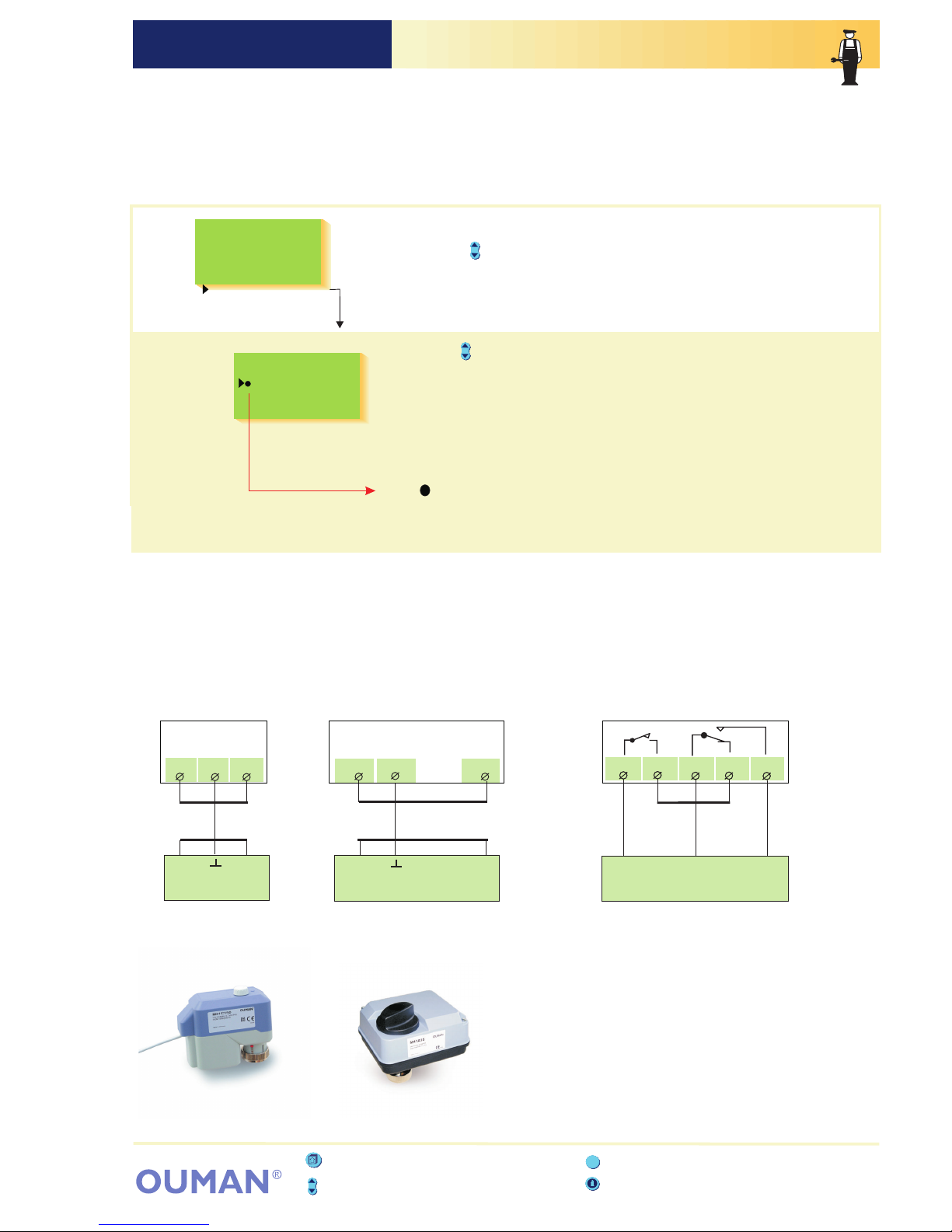
OUMAN EH-201/L ACTUATOR SELECTIONOUMAN EH-201/L
Press the button to move the cursor to the actuator control mode that
you want to use.
Press OK.
+ OK.
-
If you select the 3-point control mode, the regulator asks for the actuator's
running time. The running time indicates how many seconds go by if the
actuator drives a valve nonstop from a closed position to an open position.
Press the or button to set the time. Press
The character indicates which control mode is being used.
Directions for entering the
maintenance mode are on page 21.
The control mode for regulating circuit actuator is selected in actuator
selection. Options are either 24 VAC 3-point control or DC voltage
control (0...10V or 2...10V). If relays 1 and 2 are free, they can be
utilized to implement 230VAC 3-point control. (first choose "230V
Actuator" for the relay control mode. (See pages 26 - 28)
H1
3-p./time s
0-10V
2-10V
3-p230V s
Actuator sel
150
150
VALVE ACTUATOR CONNECTION:
25
Open
Closed
3-point 24 VAC
0-10V
or
2-10V
71 72 73 74 75
3-point controlled
actuator (24VAC)
0...10V or 2...10V DC
controlled actuator
(24VAC)
3-point controlled actuator
(230 VAC)
Open
Closed L
Actuator 230 VAC 3-point
Attention! If "230V actuator" has been selected for
relays 1 and 2, 230VAC 3-point controlled actuator
can be connected to the regulator. Selection of
relay control modes is shown on pages 26 - 28.
H1 actuator
(control output M1)
24
VAC
H1 Maint mode
Tuning values
Settings
Trends
Actuator select
Relay1 control
ESC - press to return to the previous display
Info button - gives operating instructions
Browse button - moves the cursor up and down
ESC
Press the button to move the cursor to “Actuator select”. Press OK.
H1 actuator
(control output M1)
Group select button - not in use in EH201/L
51 52 53
51 52 53 54
Ouman M31C150
Ouman M41A15

OUMAN EH-201/L RELAY 1 CONTROL SELECTIONOUMAN EH-201/L
Directions for entering the
maintenance mode are on page 21.
EH-201/L has two 230VAC/6A relays. Relay 1 is a break before make
contact relay and relay 2 is an on/off relay. The relays can be used for
many different purposes. If the relay has been selected for time
control use, it can be labeled according to its use using the text
editor (e.g., sauna, outside door etc.). Relays are time controlled in
the regulator's clock functions (p. 14 - 15). A GSM phone can be
used to bypass a relay's time program and the relay can be timer
controlled or set in a continuous ON or OFF mode.
Relay1 ctrl sel
Not in use
Pump sumr stop
Time program
Time/Outd.temp
230V actuator
GeothHeatFull
GeothHeatPart
Burner control
Temp operated
Press the button to move the cursor to the control mode that you want
to use. Press
The character indicates which control mode is being used.
OK.
H1 Maint mode
Tuning values
Settings
Trends
Actuator select
Relay1 control
Relay2 control
Press the button to move the cursor to “Relay1 control”. Press OK.
H1 Valve regul
H1 Valve close
Pump sumr stop
Pump summer stop: For each individual regul.
Outd.t.lim °C-15
R1 Time/Outd.t.
GeothH.UpPart
GeothH.UpHyst
GeothH.LowMin
GeothH.LowHyst
55
35
6
3
GeothHeatFull °C
circuit, select whether the valve will continue
regulating or whether the valve will close when
the pump stops. When you exit from this mode the
regul. asks for the outdoor temp. at which the
regulator stops the pump. The outdoor temp. limit
can also be adjusted in settings, p. 6-8 pump stop.
Time and temperature controlled relay:
Set the outdoor temperature (when the temp.
drops) at which the clock is prevented from
effecting relay 1's function. The outdoor temperat.
limit can also be set in special maintenance settings
Temperature controlled function:
The factory setting for measurement 11 in temp.
controlled functions is 55°C (setting range 0...100 °C)
and the hysteresis is 3°C (setting range 1 ... 10°C).
The setting for measurement 11 can be adjusted
either in this mode or on the user level (see p. 8, R1
temp lim.)
Setting °C
Hysteresis °C553
R1 Temp. lim.
GeothHeatAcc.
10 Hysteres
M9 Hysteres
M
55
3
3
GeothHeatPart °C
Full effect geothermal heating:
The factory setting for the temperature of the
accumulator (measurement 10) is 55°C (setting
range 5 ... 55°C). The factory setting for the control's
hysteresis is 6°C (setting range 3 ... 10°C).
Connection information:
73
L
74 75
When the relay (timing program
"OFF" mode or no electricity to actuator) the space
between contacts in the relay.
is inactive
73-74 is closed
When the relay (timing program "ON” mode)
the space between contacts
in the relay.
is active
73-75 is closed
Name change
R1 Control
Give new label
Time controlled relayOK: You can label the relay
according to its use. Move the cursor to: Give
new label and press Use of the text editor is
presented on page 9.
.
Limited effect geothermal heating:
The factory setting for the temperature of the
accumulator's upper portion (meas. 9) is 55°C
(setting range 5 ... 70°C). The factory setting is 3°C
for the control's hysteresis of both the temperature
of the accumulator's upper portion (meas. 9) and
lower portion (measurement 10). (Setting range
measurement 9: 3 ... 10°C and meas. 10: 3 ... 5°C ).
Burner control°C
Burner ON
Hysteresis705
Burner control: The factory setting at which the
burner starts up is 70°C (setting range 5…95°C)
and the hysteresis is 3°C (setting range 1…20°C)
ESC - press to return to the previous display
Group select button - moves you from one regulating
circuit to the next
Info button - gives operating instructions
Browse button - moves the cursor up and down
ESC
26

Pump sumr stop
Time program
Time/Outd. Temp
Relay 1 is not being used.
Explanation:
On the display:
Not in use
The pumps stop (relay 1's space 73 and 74 opens) and the selected valves close when the
outdoor temperat. is warmer than the "Pump stop" setting. During a stop period the regulator
starts the pumps for a few minutes every day to prevent them from getting stuck (interval use).
The regulator time controls any electric apparatus using the relay, eg. a sauna stove, door
locks. Timing programming is done in clock functions (p. 15). In the timing program's "ON"
mode the relay is activated. The control mode can also be changed using a GSM
telephone (see p. 20).
The regulator controls relay 1 by time. In the "ON" mode the relay is activated. The "ON"
mode is prevented if the outdoor temperature is colder than the relay 1's set outdoor
temperature limit. (See p. 30). Timing/ outdoor temperature control is suitable for exhaust
fan control
Control
73
75
74
1/1 speed ("ON" mode)
½ speed ("OFF"-mode)
230V actuator
When you have reserved relay 1 for 230V actuator control, the regulator automatically also
reserves relay 2 for 230V actuator control if relay 2 is free. If relay 2 is not free, the regulator
first requests to free relay 2 for 230V actuator control. After this you can begin using
230VAC 3-point control in the "actuator selection" mode (see page 25)
OUMAN EH-201/L Add. inform. about relay 1 controlOUMAN EH-201/L
27
ESC - press to return to the previous display
Info button - gives operating instructions
Browse button - moves the cursor up and down
ESC
Group select button - not in use in EH201/L
GeothHeatFull
When the control mode selected for relay 1 is "GeothHeatFull", the regulator automatically
reserves relay 2 to control the compressor of the geothermal heating and reserves
digital input 1 for geothermal heating selector switch position information (automatic position =
strip connector 21-22 closed).
Relay 1 controls heating
resistor. The regulator controls the compressor or the heating resistor according to the
accumulator temperature set by the user. The compressor and heating resistor cannot be
on at the same time.
The heating resistor is switched on at the ["GeothHeatAcc." setting -hysteresis - 10°C]
temperature ( ). is switched off at the
["GeothHeatAcc." setting - hysteresis + 2°C] temperature
Before selecting geothermal heating for relay 1, make sure that
relay 2 is in a "Not in use" mode and the geothermal heating unit selector switch (start up
/ autom.) is connected to digital input 1 strip connectors 21 - 22.
strip connector 73-74 closed The heating resistor
(strip connector 73-75 closed).
GeothHeatPart
Temp operated
The regulator controls the relay according to the boiler water temperature (meas. 10).
The relay is activated at the setting (73-75 closed) and the burner starts up. The relay is
released (73-74 closed) and the burner shuts off when the boiler water temperature
reaches the "setting” + "hysteresis” temperature. The function can be selected when
measurement 10 is connected.
The regulator controls relay 1 according to the temperature of measurement 11. The break
before make contact relay is activated at the setting (73-75 closed) and released (73-74
closed) at the end of the set hysteresis (setting - hysteresis). E.g., a cooler's compressor or
an accumulator's charging pump can be controlled with a temperature controlled relay. You
can also adjust the temperature setting for measurement 11 on the user level (seep. 8)
Burner control
When the control mode selected for relay 1 is "GeothHeatPart", the regulator automatically
reserves relay 2 to control the compressor of the geothermal heating and reserves digital
input 1 for geothermal heating selector switch position information (automatic position = strip
connector 21-22 closed). Before selecting geothermal heating for relay 1, make sure that
relay 2 is in a "Not in use" mode and the geothermal heating unit selector switch is
connected to the digital input 1 strip connectors 21 - 22 (start up / autom.). The regulator
controls the compressor and heating resistor according to the accumulator temperature set
by the user(see p. 8). The regulator alsocontrols the compressor according to the temperature
needed in the heating network. Relay 1 controls the heating resistor.
Heating resistor is switched on at the ["GeothHeatAcc" setting - hysteresis - 3 °C] temperature
(strip connector 73-74 closed). Heating resistor is switched off at the ["GeothHeatAcc." setting hysteresis + 2°C] temperature (strip connector 73-74 open). The compressor and heating
resistor can be on at thesame time. Thecompressor's and heatingresistor's control hysteresis
is set in relay 1's control mode.

OUMAN EH-201/L RELAY 2 CONTROL SELECTIONOUMAN EH-201/L
Relay2 ctrl sel
Not in use
Parallel pump
Time program
230V actuator
El.Heater ctrl
ComprGeothHeat
Ei käytössä
If pump 1 stops (the thermal relay is triggered, see digital inputs p. 34-35), the regulator
automatically connects the parallel pump (pump 2) and gives an alarm for pump 1.
(Pump 2 control occurs through connectors 71 and 72.)
L
71 72
When the relay is inactive (timing program "OFF" mode
) the space between contacts
71-72 is open in the relay.
or no electricity to actuator
H1 Maint mode
Tuning values
Settings
Trends
Actuator select
Relay1 control
Relay2 control
Special mainten
Relay 2 is an on / off relay. The following functions can be implemented
with relay 2:
1. Circulation pump control
2. Timing control
3. 230VAC actuator 3-point control (needs both relays)
4. Heating resistor control according to the temperature of meas. 10.
5. Geothermal heating unit compressor control if relay 1 is being used
to control the geothermal heating unit.
Press the button to move the cursor to the control mode that you want to
use. Press The character indicates which control mode is being
used.
OK.
Explanation:
On the display:
Parallel pump
Time program
Not in use
230V actuator
Relay 2 is not being used.
The regulator time controls any electric apparatus using the relay, eg. a sauna stove, door
locks. Timing programming is done in clock functions (p. 15). In the timing program's "ON"
mode the relay is activated.
The control mode can also be changed using a GSM telephone
(see p. 20).
When you have reserved relay 2 for 230V actuator control, the regulator automatically also
reserves relay 1 for 230V actuator control if relay 1 is free. If relay 1 is not free, the regulator
first requests to free relay 1 for 230V actuator control. After this you can begin using
230VAC 3-point control in the "actuator selection" mode (see page 25)
Connection
information:
28
ESC - press to return to the previous display
Info button - gives operating instructions
Browse button - moves the cursor up and down
ESC
Group select button - not in use in EH201/L
When relay 1 has been selected for geothermal heating unit control, the regulator
automatically reserves relay 2 to control the compressor of the geothermal heating unit.
During the compressor is switched on at the
["GeothHeatAcc." setting - hysteresis] temperature and then relay is activated
is switched off
full effect geothermal heating
(strip
connector 71-72 closed). The compressor at the "GeothHeatAcc." setting
temperature (see p. 8), and then the relay released (strip connector 71-72 open). The
compressor is turned off and the heating resistor is switched on at the ["GeothHeatAcc."
setting -hysteresis - 10°C] temperature (strip connector 73-74 closed). The heating resistor
is switched off at the ["GeothHeatAcc." setting - hysteresis + 2°C] temperature (strip
connector 73-74 open).
During the compressor is turned on when the
temperature of the accumulator's upper portion (meas. 9) drops to the ["GeothHeatAcc."
setting - hysteresis] temperature and then relay is activated (strip connector 71-72 closed).
The compressor
(strip connector 71-72 open).
The regulator also keeps the temperature of the accumulator's lower portion (measurement
10) 5°C higher than the supply water temperature (measurement 2) determined by the
regulator by turning the compressor on and off. Measurement 10 has fixed minimum and
maximum limits (min. +35°C and max. +55°C).
limited effect geothermal heating
is turned off at the "GeothHeatAcc." setting temperature and then relay
released
ComprGeothHeat
Name change
R2 Control
Give new label
Time controlled relayOK: You can label the relay
according to its use. Move the cursor to: Give new
label and press Use of the text editor is
presented on page 9.
.
El.Heater ON
Hysteresis503
El.Heater ctrl
Switching the heating resistor on and off:
Relay 2 switches the heating resistor on and off
according to the temperature of measurement 10.
The factory setting at which the heating resistor
switches on is 50°C (setting range 5…95°C) and
the hysteresis is 5°C (setting range 1…10°C).
If EH-201/L is used for burner control (see p. 26-27), the regulator can also control the
heating resistor according to the same measurement data (meas. 10). There is a separate
setting for switching on the heating resistor. The heating resistor can be used as an
extra source of heat or the main source of heat depending on whether the setting is
higher or lower than the point at which the burner starts up.
El.Heater ctrl

Restoring settings:
1. The regulator restores factory settings to the charasteristic heating
curve settings.
2. Eliminates clock functions
3. Restores user and maintenance level settings
4. Selects automatic control for the operating mode
5. Selects the basic regulator for the regulator type.
6. Identifies the connected sensors and take into use regulating circuit.
7. Restores factory settings to the tuning values and trend sampling intervals.
8. Selects the 3-point control for actuator control which has a running
time of 150s.
9. Relay controls are not in use.
10. Measurements are not read from the bus.
11. Erases the telephone number and restores the factory settings
to the modem settings.
Original factory settings can be restored with the regulator in the
following manner:
Press the button to move the cursor to "Special mainten.
The cursor is at "Rstore settings". Press
”.
Press OK.
OK.
Directions for entering the
maintenance mode are on page 21.
Restore original factory settings:
ORIGINAL FACTORY SETTINGS:
21.5 °C
0°C
15 °C
70 °C
4,0 °C
0°C
0°C
0°C
2°C
30°C
55°C
55°C
User level settings:
Room temperature
Temp. drop (supply water)
Min. allowed supply water
Max. alllowed supply water
Room compensation ratio
Wind compensation ratio
Sun compensation ratio
Pre-increase
Autumn drying
Valve close
Geothermal heating acculmul. temp.
Relay 1 temperature limit
Characteristic heating curve:
80
65
50
35
20
20 0 -20 °C
H1 Curve:
0 = 41°C
+
-20 = 58°C
20 = 18°C
Start function:
2h
0h
Maintenance level settings:
Outdoor temp. delay
Pre-increase
Settings:
Factory setting:
Relays:
Operating mode:
Actuator selection:
Tuning values:
0.5h
70°C
5°C
15°C
10°C
30°C
999kW
99.9 l/s
6°C
-15°C
75°C
60 min
Special maintenance settings:
Room temperature delay
Return water maximum
Return water min. at 0°C
Supply water min at 0°C
Return water min at -20 °C
Supply water min at -20°C
The amount of deviat. from the H1/
R1 temp. operated supply water
setting, which causes the alarm
The duration of the deviation that
causes the alarm
Output limit
Water flow limiting function
½ exhaust
Relay 1 outdoor temperature limit
OUMAN EH-201/L RESTORING SETTINGOUMAN EH-201/L
Restore original
Factory settings
No
Yes
H1 Control modes
Automatic ctrl
Nominal oper.
Reduced oper.
Stand-by
Manual mech.
Manual electr.
Special mainten.
Rstore settings
Settings
Meas. 3 setting
Dig1 selection
Dig2 selection
LON initializ.
Net measurement
Text message
H1
3-p./time 60s
0-10V
2-10V
3-p230V 60s
Actuator sel
Start function
H1 Basic regul
H1 Self-learn
H1 Tuning values
P-area: 140°C
I-time: 50s
D-time: 0.0s
Relay1 ctrl sel
Not in use
Pump sumr stop
Time program
Time/Outdr tmp
230V actuator
Burner control
Temp operated
Relay2 ctrl sel
Not in use
Parallel pump
Time program
230V actuator
El.Heater ctrl
ComprGeothHeat
ESC - press to return to the previous display
Info button - gives operating instructions
Browse button - moves the cursor up and down
ESC
Press the button to move the cursor to "Yes”.
Press OK.
Group select button - not in use in EH201/L
29

Factory
settings:
Explanation:
The average inside temperature measurement time which the
room compensation uses.
Return water maximum allowed temperature at which the
regulator begins lowering the return water temp.
Freeze protect limit. Minimum return water temperature when
the outdoor temperature is 0°C.
Freeze protect limit. Minimum return water temperature when the
outdoor temperature is -20°C.
Lower limit of supply water during a free temperature drop
when the outdoor temperature is 0°C. (stand-by function)
Lower limit of supply wate r during a free temperature drop
when the outdoor temperature is -20°C. (stand-by function)
Maximum district heating water flow at which output limiting
begins.
Maximum district heating output at which output limiting begins.
Drop in supply water temperature when the exhaust fan is at
½ speed.
The outdoor temp. limit for relay 1 (in use when "time /outdoor
temperature control has been selected for relay 1's control
mode")
H1 supply water temperature deviation from the setting
determined by the regulator which causes th alarm
Temp. (meas. 11) deviation from the setting of "R1 Temp
operated" which causes the alarm. This setting appears if "Temp
operated" has been selected in the relay1 control mode ( p. 26).
The alarm goes off if the deviation has lasted for the set time.
Range:
0...2
25...95
5...20
10...50
5...20
10...50
1...75
1...75
0...90
0...999
0.1...99.9
0...10
-30...+20
INFORMATION ABOUT SPECIAL MAINTENANCE SETTINGS:
Directions for entering the
maintenance mode are on page 21.
0.5h
70°C
5°C
15°C
10°C
30°C
75°C
75°C
60 min
999 kW
99.9 l/s
6°C
-15°C
Settings:
Press the -button to move the cursor to "Settings".
Press OK.
OUMAN EH-203 ERIKOISHUOLTO AsetusarvotOUMAN EH-203
OUMAN EH-201/L SETTINGSOUMAN EH-201/L
Settings
Ret.min (0)
Ret.min (-20)
H1SuppMin(0)
H1SupMin(-20)
Room delay h
RetWat.max °C
H1 Dev. alarm
R1 DevAlaM11
DevAlaDela min
Output lim kW
WaterLim l/s
1/2exhst °C
R1 Outd. °C
0.5
70
5
15
10
30
999
6
-15
75
75
60
99.9
Special mainten.
Rstore settings
Settings
Meas. 3 setting
Room delay
RetWat. max
Ret. min (0°C)
Ret. min(-20°C)
H1 SuppMin (0°C)
H1 SuppMin(-20°C)
½ exhst
R1 Outd.
H1 Dev. alarm
R1DevAlaM11
DevAlaDela
Output lim
WaterLim
In the Ouman EH-201/L heating regulator the user can adjust most of
the settings (see settings p. 6-8). Some of the settings that control the
regulator's functions can be set in the maintenance mode (see page 23)
and some in special maintenance. Seldom needed settings can be
adjusted in special maintenance.
Press the button to move the cursor to the parameter that you want
to change. Press
Press the or button to change the setting. PressOKOK..
-+
30
ESC - press to return to the previous display
Info button - gives operating instructions
Browse button - moves the cursor up and down
ESC
Group select button - not in use in EH201/L

OUMAN EH-201/L MEASUREMENT 3 SETTINGOUMAN EH-201/L
Directions for entering the
maintenance mode are on page 21.
Erikoishuolto
Aset.palautus
Asetusarvot
Mitt. asetukset
Meas. 3 setting
H1 Room temp
Wind meas.
Sun meas.
Measure 3
Not connected
Comp/Meas.data
Min / 30%
Max / 70%
More information about sun and wind sensor connection on the next
page
Labeling measurement 3 using the text editor:
The factory setting for free measurement is
labelled "Meas. 3".
Relabeling is shown on page 9.
Press
Press the or button to set a limit and
press to confirm.
OK.
+
OK
-
The character indicates which measurement has been chosen for
measurement 3.
Selecting measurement 3:
Setting limits for the wind or sun sensor measurement message:
You must set compensation limits for wind or sun measurements.
The minimum indicates where in the transmitter's measurement area
the compensation begins and the maximum indicates at which
measurement area the compensation is at maximum value.
Name change
Measure 3
Give new label
Special mainten.
Rstore settings
Settings
Meas. 3 setting
Dig1 selection
In this special maintenance mode, measurement 3 can be
changed to or wind or sun
compensation measurement. The H1 room compensation is a factory
setting. Free temperature measurement is labeled "Meas. 3”. This label
can be changed
just a free temperature measurement
using the text editor.
Press the button to move the cursor to what you want to connect
to measurement 3.
Press
OK.
Press the button to move the cursor to "Meas. 3 setting". Press OK.
ESC - press to return to the previous display
Info button - gives operating instructions
Browse button - moves the cursor up and down
ESC
Group select button - not in use in EH201/L
31

OUMAN EH-201/L Measurement 3: Wind/ Sun meas.OUMAN EH-201/L
Supply water
Wind compensation
61420
m/s
10 V
0V
30% 70% 100%
min.compens. limit max.compens. limit
Compensation area calculation
°C
Picture. Wind compensated supply water temperature curve.
Wind sensor meas. area
Example: A wind sensor is in use which has a measurement area of
0...20 m/s. You want wind compensation to begin when the wind
velocity is 6 m/s (min. limit) and compensation to be at maximum
value when the wind velocity is at least 14 m/s (max. limit). Calculate
how many percent the wind compensation limits (min. limit and max.
limit) are from the measurement area' s maximum (=20 m/s), and set
them as the minimum and maximum compensation percents.
Comp/Meas. Data
Min / 30%
Max / 70%
Ouman EH-201/L
Measurement
3
0-20mA
(4-20mA)
Wind and sun
meas. transmitter
250
Add
shunt
resistor
1k
Add series
and
shunt
resistor
1k
Wind or sun sensor connection:
x 100% = x 100% = 30%
Min.limit
meas. area's max.
6 m/s
20 m/s
Max limit
meas. area`s max.
14 m/s
20 m/s
Min. compens.=
Max.compens.= x 100% = x 100% = 70%
If measurement sensors that begin from zero are in use, (0...10V or
0...20mA) set the values calculated with the above formula as the
minimum and maximum compensation percents.
Setting the min. and maximum compens. when the sensor's measurem. area does not begin at zero.
1. Calculate the compensation percents with the "min. compens." and
"max. compens." formula.
2. See which values should be set for the regulator from the
equivalency table.
0-10V
(2-10V)
Wind and sun
meas. transmitter
Ouman EH-201/L
Measurement
3
2-10V
4 -20 mA
28 %
36 %
44 %
52 %
60 %
68 %
76 %
84 %
92 %
100 %
Value obtained
from the formula
10 %
20 %
30 %
40 %
50 %
60 %
70 %
80 %
90 %
100 %
When you connect the wind or sun sensor to measurement 3,
you instruct the regulator when you want the wind or sun compens.
to function. Calculate compensation limits (min/max) in the same way
regardless of which sensor is in use.
The wind and sun compensation ratio indicates how many degrees
compensation changes the supply water temperature and the user can
set this. (See settings p. 6-7).
The wind and sun sensor measurement signal can be 0...10 V, 2...10 V,
0...20mA or 4...20 mA. Adjust the sensors with the regulator's resistors
so that the measurement message that comes from the regulator is
always 0...5 V.
32

OUMAN EH-201/L DIGITAL INPUTS 1 AND 2OUMAN EH-201/L
Directions for entering the
maintenance mode are on page 21.
Dig1 selection:
Alarm Dig 1
Exhaust ½pwr
Home/away
PumpI th.relay
DH Energy MWh
DH Water m3
Watr consmp. m3
Geoth.Heat.Op.
DH Energy set.
pulse = kWh0
Watr consm set
pulse = l
0
Special mainten.
Rstore settings
Settings
Meas. 3 setting
Dig1 selection
Dig2 selection
LON initializ.
Name change
Alarm Dig 1
Give new label
Press the button to move the cursor to Dig 1 or Dig 2 selection .
Press
Press the button to move the cursor to indicate which information
has been connected to the Dig channel in question. Press
The character indicates the selection made.
””
OKOK.
.
EH-201/L has two digital inputs. They can be used either
for receiving alarms, receiving information about exhaust fan running
at ½ speed, receiving a temperature drop command from the home /
away switch, or receiving information about running circulation pump 1
(if pump 1 stops the regulator can be programmed to start a parallel
pump). District heating energy and water meter pulses can also be
connected to digital inputs.
If relay 1 has been reserved for geothermal heating unit control, the
geothermal heating unit selector switch (start up / automatic) is
connected to digital input 1 (strip connector 21-22).
DH Watr metr set
pulse l0
Connection guide:
21
2 x 0.8
Dig 2
Dig 1
Pulse information (switch information)
22
23
24
2 x 0.8
Pulse information (switch information)
ESC - press to return to the previous display
Info button - gives operating instructions
Browse button - moves the cursor up and down
ESC
Group select button - not in use in EH201/L
Alarm use: Alarm switch information. When the
switch is closed, an alarm goes off. You can
use the text editor to label the alarm, e.g.,
Order oil! (see p. 9). In the event of an alarm,
the regulator sounds the alarm and indicates
on the display from which digital input the
alarm came from. Transferring the alarm to a
GSM phone (see p. 39).
Pulse information from the district heating
energy meter: OK
OK
Pulse information from the district heating
water meter: OK
OK
Pulse information from the facility's water
meter: OK
OK
.
.
.
.
.
.
Press Set the number of
kWh equivalent to one pulse and press
District heating energy consumption (MWh) and
the momentary (5 min. follow-up period) district
heating power consumption (kW) can be seen on
the regulator's measurements display.
Press Set the number of
liters equivalent to one pulse and press
District heating water consumption (DH m3) and
the momentary district heating water
consumption (Inst. l/s) can be seen o the
regulator's measurements display.
Press Set the number of liters
equivalent to one pulse and press The
facility's water consumption (Water m3) can be
seen on the regulator's measurements display.
33

OUMAN EH-201/L Addit. inform. about digital inputsOUMAN EH-201/L
Alarm Dig 1
Exhaust ½pwr
Home/away
Pump1 th.relay
DH Energy MWh
DH Water m3
Watr consmp. m3
GeothHeatCtrl
Alarm switch information. When the switch is closed an alarm goes off.
Exhaust fan ½ speed information. When the switch is closed the exhaust fan is at ½
speed.
Away switch information. (switch closed, reduced temperature mode is on).
Pump 1 thermal relay switch information. When the switch is closed pump 1 does not
run. In that case the regulator starts the parallel pump and gives an alarm if r elay 2
is connected to alarms.
Pulse information from the district heat energy meter.
Pulse information from the district heat water meter (m ).
Pulse information from the facility water meter .
When relay 1 is used for geothermal heating control, the geothermal heating selector
switch (start up / automatic) is connected to strip connectors 21-22 .
When
The information is used to lower the heat when the exhaust fan is at ½
speed. The amount of the drop is given in special maintenance settings. (p. 28, ½ exhst)
(m )
(see pages 26 - 27)
the switch opens the dig 1 space. In automatic position strip
connector 21 - 22 is closed.
3
3
starting up
Select full effect or limited effect geothermal heating in
relay 1 control selection and after this selection you can change the settings that switch
the compressor and heating resistor on and off.
Explanation:On the display:
ESC - press to return to the previous display
Info button - gives operating instructions
Browse button - moves the cursor up and down
ESC
Group select button - not in use in EH201/L
Start up:
Automat function:
The geothermal heating unit's accumulator is heated to the "Accumulator." setting temperature with the help
of the compressor. The heating resistor cannot be on. Position of the geothermal heating unit selector switch: Start
up (the switch opens the dig 1 space)
The EH-201/L regulator attempts to keep the temperature of the accumulator at the
"Accumulator" temperature (meas.10) set by the user by controlling the compressor or heating resistor following manner:
Function and temperature limits The state of relay Strip connector
relay 2 is active
relay 2 is inactive
relay 2 is inactive
relay 1 is inactive
relay 1 is active
71-72 closed
71-72 open
71-72 open and
73-74 closed
73-74 open
Compressor is switched on,
Compressor is switched off,
Compressor is switched off and heating resistor is switched on,
Heating resistor is switched off,
when
-the accumulator's temp. drops to the ["GeothHeatAcc" setting - "Hysteresis"] temperature
when
- the accumulator's temperature rises to "GeothHeatAcc" (measurement 10) temperature
when
the accumulator's temp. drops to the ["GeothHeatAcc" setting - "Hysteresis" - 10 °C] temp.
The accumulator`s temp has to stay 20 min under this level before the heating resistor is switched on
when
the accumulator's temp. rises to ["GeothHeatAcc" setting - "Hysteresis" + 2°C] temperature
Start up function
Automat function:
works same way than automat function, but heating resistor is not able to switched on.
The compressor can switch on according the accumulator upper part temperature (meas. 9) or
accumulator lower part temperature (meas. 10) if the temperature of the accumulator lower part is under 55°C
(maximum allowed accumulator lower part temperature). The heating resistor also switched on according t the
temperature of accumulator upper part (measurement 9), if the effect for the compressor is not sufficient.
Functions and temperature limit s The state of relay Strip connector
relay 2 is active
relay 2 is inactive
relay 1 is inactive
relay 1 is active
71-72 closed
71-72 open
73-74 closed
73-74 open
Compressor is switched on,
Compressor is switched off,
and
and
Compressor is switched off,
Heating resistor is switched on,
Heating resistor is switched off,
when
- the accumulator's upper part temp. drops to ["GeothH.UpPart" setting - "GeothH.UpHyst"] or
- the accumulator's lower part temperature drops to ["Supply water temperature determined by
regulator" + 5°C - "GeothH.LowHyst"] or
- the accumulator's lower part temperature drops to "GeothH.LowMin"
when
- the accumulator's upper part temperature reach "GeothH.UpPart" (meas. 9)
- the accumulator's lower part temp. reach ["Supply water temp. determined by regulator" + 5°C]
- the accumulator's lower par t temperature is over ["GeothH.LowMin" + "GeothH.LowHyst"]
when
- the accumulator's lower part temp. rises to 55°C (accumulator's lower part max. allowed temp.)
when
- the accumulator's upper part temp. drops to ["GeothH.UpPart" setting - "GeothH.UpHyst"-3°C]
when
- the accumulator's upper part temp. reach ["GeothH.UpPart" setting - "GeothH.UpHyst"+2°C]
always
A. Full effect geothermal heating:
Additional information about geothermal heating:
B. Limited effect geothermal heating:
34

OUMAN EH-201/L LON INITIALIZINGOUMAN EH-201/L
Directions for entering the
maintenance mode are on page 21
LON initializ.
No
Yes (Service
switch)
Connection guide:
LON net (78kbps)
A
C
Eg. LONAK 2x1,3 mm
2
LON-200 adapter card
An installation guide comes with the LON-200
adapter card.
Special mainten.
Rstore settings
Settings
Meas. 3 setting
Dig1 selection
Dig2 selection
LON initializ.
Net measurement
Ouman EH-201/L has an LON-200 adapter card (optional equipment)
(contains an FTT-10A bus adapter) which makes it possible to connect
the regulator to an LON field bus. In this special maintenance mode
you can control the Neuron processor's service pin which is on the
LON-200 card so that the Neuron sends the bus its own identification
(48 bit Neuron ID). This procedure is necessary when initializing
EH-201/L + LON-200 into the facility's LON net.
Press the button to move the cursor to .
Press
"LON initializ.”
OK.
Press the button to move the cursor to
. Press
"Yes
(Service switch)"
OK.
ESC - press to return to the previous display
Info button - gives operating instructions
Browse button - moves the cursor up and down
ESC
Group select button - not in use in EH201/L
35

OUMAN EH-201/L NET MEASUREMENTOUMAN EH-201/L
Directions for entering the
maintenance mode are on page 21.
Net measurement
Outdr tmp meas
H1 Room meas.
Wind measure
Sun measure
DH Energy MWh
Watr consm.m3
OK.
OK.
Setting limits:
-+
Press
Press the or button to set the limit and
confirm by pressing
Comp/Meas. data
min/ m/s
max/ m/s
0.0
10.0
Comp/ Meas. data
min/ lx
max/ lx
0
9000
By using the button to browse, you can see which measurements can
be read from the net.
Move the cursor to the measurement you want
and press
If you want to select an serial interface for the
measurement in question, move the cursor to Yes
net and press The character indicates
that the measurement information is read from
the net.
OKOK.
.
Browsing the net measurements:
You must set the compensation limits for wind and sun
measurements. The minimum indicates when compensation begins and
the maximum indicates when compensation is at a maximum value.
Set the limits for wind measurement as wind speed (m/s) and for sun
measurement as amount of light (lx).
Outdr tmp meas
No net
Yes net
Setting net measurements:
Setting wind or sun measurements (net):
Attention! Set wind and sun compensation in "Settings" (see page 6-7).
Special mainten.
Rstore settings
Settings
Meas. 3 setting
Dig1 selection
Dig2 selection
LON initializ.
Net measurement
TextMessageSett.
Press the button to move the cursor to .
Press
"Net measurement”
OK.
Ouman EH-201/L has an LON-200, EH-485 and
MODBUS-200 adapter card (optional equipment). In this special
maintenance mode you can select which measurement information is
to be read from the net.
If you selected to read wind or sun measurements from the net,
you must set the compensation area in this mode.
ESC - press to return to the previous display
Info button - gives operating instructions
Browse button - moves the cursor up and down
ESC
Group select button - not in use in EH201/L
36
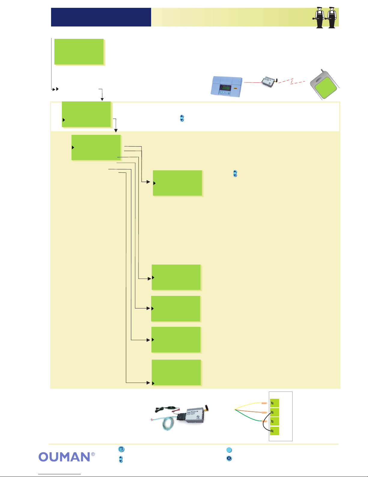
Measurements
H1 Supply=52/
H1 Room=21.2/
H1 Ret.water=28/
Outdoor=-15/
H2 Supply=48/
Exhaust=25/
OUMAN EH-201/L MODEM SETTING (TEXT MESSAGE CONNECTION)OUMAN EH-201/L
TextMessageSett.
Alarm GSM1 nr
Alarm GSM2 nr
Device ID
MessageCentreNr
PIN-code
Modem type
Modem connect
Data link
Text message
The regulator's strip connector B-D space is connected with a jumper
wire.
Press the button to move the cursor to . Press
"Text message”
OK.
Telephone nr.
Change
PIN-code
Change
----
Modem type
Falcom A2D
Siemens M20T
Ouman/Fargo
Press the button to move the cursor to "Change”.
Press . "O” blinks.
Write the telephone number using the text editor.
You can move forward or backward in the character
OK
Give a telephone number that the regulator automatically sends a text
message to about an alarm in the event of an alarm. At first the
alarm message is only sent to the GSM number 1. If the alarm is
not acknowledged from this number, after five minutes the regulator
sends a new alarm to both the GSM 1 and 2 numbers.
The regulator can be given a device ID, which functions as the device's
secret password and address information. The device ID can be freely
labeled. The device ID is always written in front of the keyword when
using the GSM to communicate with the regulator.
Telephone nr.
Change
Device ID
Not in use
In use 0000
GSM-modem
GSM network
Connecting the GSM modem's D-9 con nector to the EH-201/L regulator:
g
r
e
e
n
b
r
o
w
n
y
e
l
l
o
w
Ouman
EH-201/L regulator
A B C D
jumper wire
Installing receivers for alarm messages:
Device ID:
In order to communicate via text messages, the regulator must be connected to a
GSM modem (optional equipment). The modem comes with an adapter cable
equipped with a D-connector that is used to connect modem to the regulator. The
regulator's strip connector B-D space is connected with a jumper wire. GSM
modem connection is done in start functions. The regulator automatically
initializes the GSM mode in two hour intervals. This prevents the GSM from
becoming disconnected in the event of power failures.
Directions for entering the
maintenance mode are on page 21.
Special mainten.
Rstore settings
Settings
Meas. 3 setting
Dig1 selection
Dig2 selection
LON initializ.
Net measurement
Text message
row with the or button. Confirm the number by pressing , then
the same number that you selected will blink in the next space.
Whichever has been selected last can be deleted by pressing . If
you press the button for a while, the number will be deleted and
the number that was previously fed will remain in effect. When you
are ready, press for a while (over 2 secretary.).
-+OK
ESC
ESC
OK
Move the cursor to "In use”. Press . "0" blinks.
Write a device ID that has a max. of 4 characters.
The text editor has the letters A…Z and the
numbers 0…9. You can move forward or backward
in the character row by pressing the or button.
Confirm the character by pressing .
Give the operator-specific message center number
with or button. Confirm by pressing .
Give the SIM card's PIN code. The regulator will
not initialize the GSM modem before the PIN code
is installed. The SIM card has to be put in the
GSM telephone to change the modem's PIN
code. When you have changed the PIN code,
install the SIM card back in the modem.
EH-201/L is compatible with Falcom A2D and
Siemens M20T modems.
OK
OK
OK
+-
Installing the number for the message center:
+-
Installing the modem's PIN for the regulator:
Selecting the modem type:
ESC - press to return to the previous display
Info button - gives operating instructions
Browse button - moves the cursor up and down
ESC
Group select button - not in use in EH201/L
37
GSM-modem
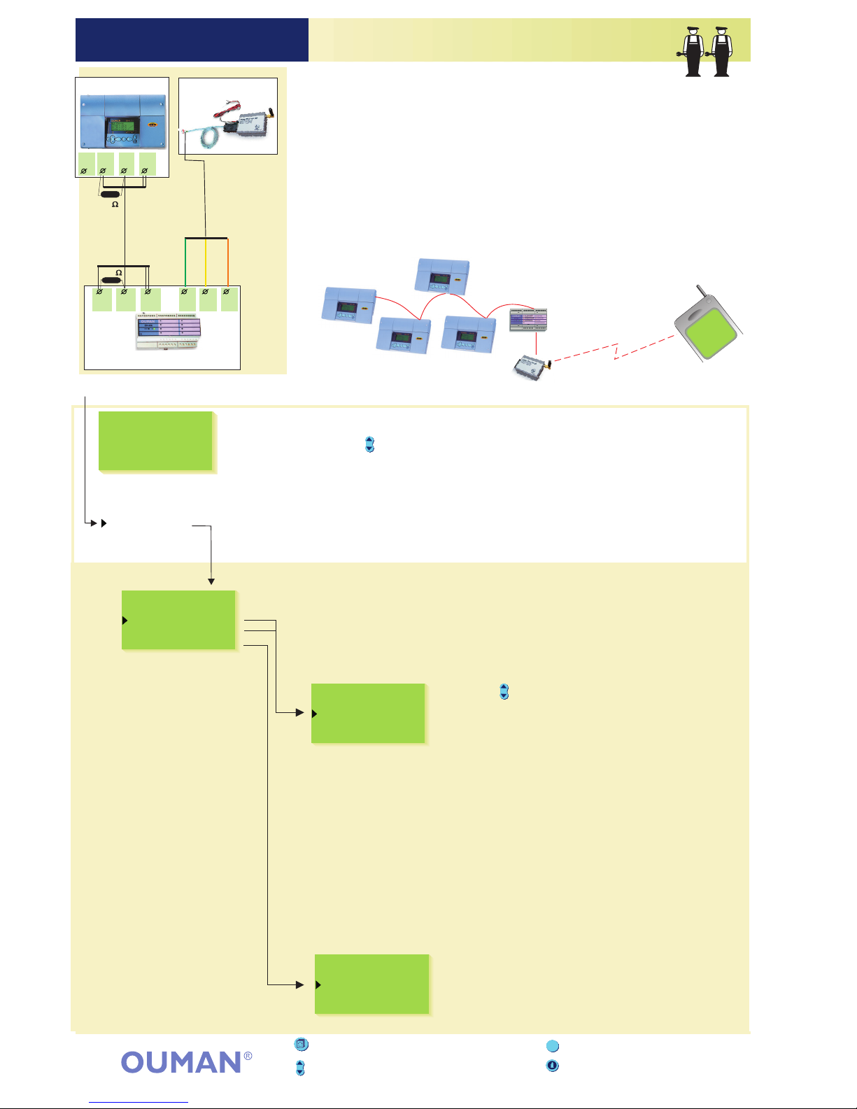
OUMAN EH-201/L TEXT MESSAGE SETTINGS (NET SOLUTION)OUMAN EH-201/L
TextMessageSett.
Alarm GSM1 nr
Alarm GSM2 nr
Device ID
Telephone nr.
Change
A GSM telephone can receive alarms and also acknowledge them. A
telephone number is given here that the regulator automatically sends a
text message to about an alarm in the event of an alarm.
At first the alarm message is only sent to GSM number 1. If the
alarm is not acknowledged from this number, after five minutes the
regulator sends a new alarm to both GSM numbers 1 and 2
That which is presented on this page is in effect when a modem
has not been directly connected to the regulator. Communication occurs
through the regulator's RS-485 field bus. Many regulators can be
connected to the system by using the EH-485 bus adapter card and
connecting a GSM modem to the field bus through the master device,
EH-686.
Regulators that are connected to the bus will be given a device ID
(e.g., TC 1) so the system will identify which regulator is being
communicated with. The device ID always has to be written in front of
the keyword when communicating with the regulator.
Installing the device ID:
When an RS-485 field bus is used for text message connections, the
regulators are identified using a device ID. The device ID which is 4
characters long and can be freely labeled using the text editor
functions as address information. The device ID is given as follows.
Special mainten.
Rstore settings
Settings
Meas. 3 setting
Dig1 selection
Dig2 selection
LON initializ.
Net measurement
Text message
Directions for entering the
maintenance mode are on page 21.
Press the button to move the cursor to .
Press
"Text message”
OK.
Press the button to move the cursor to
"Change”. Press . "O” blinks. Write the
telephone number using the text editor. You can
move forward or backward in the character
OK
row with the or button. Confirm the number by pressing , then
the same number that you selected will blink in the next space.
Whichever has been selected last can be deleted by pressing . If
you press the button for a while, the number will be deleted and
the number that was previously fed will remain in effect. When you
are ready, press for a while (over 2 secretary.).
-+OK
ESC
ESC
OK
Installing receivers for alarm messages:
Move the cursor to "In use”. Press . "0"
blinks. Write a device ID that has a max. of 4
characters by pressing the or button.
Confirm the character by pressing .OK
OK
+-
Device ID
Not in use
In use 0000
ESC - press to return to the previous display
Info button - gives operating instructions
Browse button - moves the cursor up and down
ESC
Group select button - not in use in EH201/L
GSM-modem
EIA-232
RS-485 - field bus
TC 4
TC 3
TC 1
TC 2
GSM network
Master device
(I/O -master)
Measurements
H1 Supply=52/
H1 Room=21.2/
H1 Ret.water=28/
Outdoor=-15/
H2 Supply=48/
Exhaust=25/
38
DATAJAMAK
2x(2+1)x0,24
C
AB
D- D+ B
C
A
I
I
Green
Yellow
Brown
Fargo modem
Modem's
connection wire
EH-201/L
EH-60/ EH-686
TC01
D
120
120
TC00
supply voltage feed
5...32VDC
Example of bus connection
Master
device

Ouman EH-201/L
regulator
T11T1
1
A
B
C
OUMAN EH-201/L Direct computer connectionOUMAN EH-201/L
Connection guide:
Connecting the regulator directly to a PC:
D-25 connector (female)
are connected
together
at the PC end.
DCD
DSR
DTR
DATAJAMAK
2x(2+1)x0,24
8
20
6
4
5
RTS
CTS
TX
RX
GND
DATAJAMAK
2x(2+1)x0,24
543 21
9876
2
5
3
PC
PC
Ouman EH-201/L
regulator
DCD
DSR
DTR
1
4
6
7
8
RTS
CTS
TX
RX
GND
3
7
2
25 24 23 22 21 20 19 18 17 16 15 14
13 12 11109876543 21
The Ouman EH-201/L regulator can be connected directly to a computer.
DATAJAMAK cable is used to make the connection.
Attention! If there are interferences in data transfer, try connecting
the cable cover to the D-25 connnection pin no. 1 (protective GND).
are connected
together
at the PC end
are connected
together
at the PC end
are connected
together
at the PC end.
Connector pin number
Connecting the regulator directly to a PC:
D-9 connector (female)
T11T1
1
A
B
C
Connector pin number
Ouman EH-201/L
EIA-232
max. 25 m
39
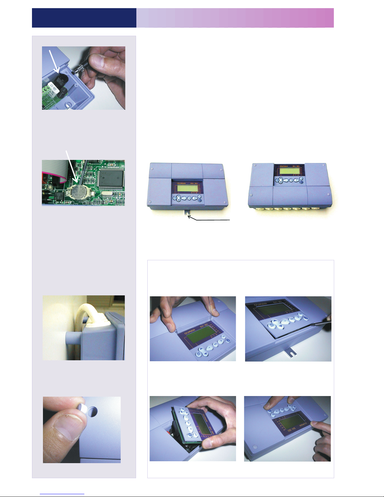
OUMAN EH-201/LOUMAN EH-201/L
INSTALLATION AND MAINTENANCE GUIDE
(standard factory delivery)
EH-201/L is fastened to its mounting base with three
screws (two mounting points under the cover in the
connection space and one in the installation bracket.
Cables can be brought for the regulator from above
(standard factory delivery) or from below. In addition, there
are 6 cable through-holes in the bottom of the regulator
case which can be opened, e.g., with a screw driver. Then
the cables can be brought into the connection space
through the bottom.
(turn the keyboard/display unit)
The cables can be routed between the
regulator and installation base when
spacers are used to mount the
regulator.
Remove the clear cover. Press
as illustrated in the picture and
pull the cover out of place.
Detach the keyboard / display
unit carefully by prying it with
a screwdriver.
Turn the keyboard / display unit
into the opposite position.
Press the keyboard / display unit
carefully into place.
Complete installation by pressing the
plastic plugs into the screw holes.
Switch off the voltage from the regul.
Press the fuse socket and turn it counter
clockwise. Change the 160mA (5x20mm)
glass tube fuse. Press and turn the fuse
socket clockwise into place.
EH-201/L has a backup that saves the
time and time program in case of a
short power failure. If the time is not
correct after the power failure, the
battery must be changed. Battery type:
Lithium button battery CR 1220, 3V.
Unfasten the regulator's fuse (see the
topmost picture). Carefully pry the old
battery from its holder, for eg., with a thin
screw driver. Push the new battery into
the holder with the + end up. The old
battery can be put into the garbage.
Changing the fuse:
Changing the cabling direction:
Spacers:
Plugs:
Mounting guide:
Screw the regulator to the wall using the installation bracket. Position
the unit so it is level. Screw the regulator firmly into place using two
screws through the connection space.
Installation bracket
If you want to bring the cables to the regulator from below, you
must turn the keyboard / display unit according to the following
instructions.
Cabling from above: Cabling from below:
Changing the battery:
40

()Name using the text editor
Free measurement
Meas.3
Meas.4
Meas.9
Meas.10
Meas.11
Dig 1
Dig 2
Actuator H1
Relay 2
Relay 1
EH-201/L heating regulator
Net
connection
Meas.1
Meas.2
Cabling
Field apparatus
Outdoor sensor
H1 supply water sensor
H1 room sensor
Free measurement
(Name using the text editor)
Free measurement
)(Name using the text editor
Relay control
R2 (230VAC, 6(1)A)
Relay control
R1 (230VAC, 6(1)A)
Distribution center
power supply 230 VAC
H1 return water sensor
Pulse information (contact inform.)
e.g. alarm information
Pulse information (contac inform.
e.g. alarm information
)
Actuator control
output M1
(24 VAC)
Open
Closed
L
L
N
N
L
A
C
D
2
TMO
TMW or TMS
2 x 0.8
T2
3
4
TMR
2 x 0.8
T3
TMW or TMS
2 x 0.8
T4
9
10
TMW or TMS
2 x 0.8
T9
TMW or TMS
2 x 0.8
T10
11 21
TMW or TMS
2 x 0.8
T11
2 x 0.8
22 24
X1
2 x 0.8
X2
31 51
2 x 0.8
K1
52
54
3 x 0.8
DATAJAMAK
2x(2+1)x0,24
EIA-232 RX
EIA-232 TX
EIA-232 GND
NET
B
1
T1
2 x 0.8
23 32 53 71 73
2 x 1.5 N
RE 2
3 x 1.5 N
RE 1
74
81 82
3 x1.5 S
230V 50Hz
72
75
83 84
L
Free measurement
Alarm center
Alarm
contact
Alarm information from regulator
max. 46V, 1A
24 VAC
0...10V
DC- input
51
52
54
3-point controlled
actuator
DC -voltage
controlled actuator
EH-201/L regulator
M1
OUMAN EH-201/L GENERAL CONNECTION DIAGRAMOUMAN EH-201/L
41
Green
Yellow
AB
C
D
Jumper
wire
Modem's
connection
Brown
Fargomodem's
connection
wire
RS-485 bus
connection
See example,
page 38

OUMAN EH-201/L OPTIONAL EQUIPMENTOUMAN EH-201/L
ESC - press to return to the previous display
Group select button - moves you from one regulating
circuit to the next
Info button - gives operating instructions
Browse button - moves the cursor up and down
ESC
LON-200
EH-485
Ouman has an EH-485 bus adapter card available as optional equipment
which makes the EH-201/L interface compatible with the RS-485 field
bus. This offers the choice of economically connecting the EH-201/L
regulators to the monitor unit.
MODBUS-200 is a bus adapter card which makes the EH-201/L
interface compatible with the MODBUS RTU field bus. The physical
interface to the field bus is galvanically isolated RS-485 network.
GSM-modem
When a GSM modem is connected to the regulator, a GSM telephone can
be used to communicate with the regulator via text messages.
EH-686
An input/output unit which contains relays, analog and digital inputs as well
as analog outputs. The unit makes it possible to carry out time controlled
relay functions, transfer alarms using digital inputs and make an individual
regulating circuit. EH-686 can also function as a master in the Ouman
RS-485 bus by directing traffic in the net.
LON -200 is an adapter card which changes the EH-200 series regulators'
serial communication bus so it is compatible with the LON field bus. An
installation guide comes with the LON-200 adapter card.
PAN-200
With the help of panel installation kit PAN-200 the regulator EH-201/L is easy to
install for example to the control cabin. The size of the installation hole is
222 mm x 138 mm.
MODBUS-200
42

43
OUMAN EH-201/L INDEXOUMAN EH-201/L
Actuator control mode 25
Actuator selection 25
Alarms 18, 33
Alarm labeling 18, 33
Alarms directed to a GSM 37, 38
Approvals 44
Automatic control 12, 20
Autumn drying 6, 7
Battery changing 40
Burner control 8, 26 - 28
Bus adapter card 35, 42
Cabling 40
Circulat. pump summer stop.8,27
Clock programs 14, 15
Connection instruction 41
Deviation alarm 18, 30
Deviation alarm delay 30
Device ID 37, 38
DH energy consumption 9, 10, 33, 34
DH output limiting 30
DH water flow limiting 30
DH water consumption 9,10, 33, 34
Digital inputs 33, 34
Door locks 15, 20
Exhaust fan ½- speed 33, 34
Energy consumption 10, 20, 33, 34
Field bus 36
Fire alarm 18
Floor heating 5
Forced mode 12, 15, 20
Fuse changing 40
Freeze protect limit 30
Freezing risk alarm 18
Geothermal heating 8, 26-28,33, 34
Geoth. heat. accumulator 8, 26, 27
GSM-modem 37, 38, 42
GSM-functions 19, 20
Heating curve setting 4, 5, 20
Heating resistor control 28
Home/away switch 33, 34, 6
Input/Output unit 38, 42
Installation instructions 40
Language change 16
LON-bus adapter card 35, 42
LON initialization 35, 36
LON-measurements 36
Manual operation 12, 20
Maximum limit (supply water) 6
Measurements 9, 10, 20,31, 32, 36
Measurements labeling 9
Minimum limit (supply water) 6
MODBUS adapter card 36, 39, 42
Modem connection 37, 38
Moisture risk 18
Name change 9
Net measurements 36
Night drop 6, 12, 20, 33, 34
Nominal temperature 12, 20
Oil burner control 26, 27
Oil finish alarm 18
Outdoor temperature 10, 36
Outdoor temperature delay 23
Parallel pump 33, 34
PID regulation 22
Preheating for air conditioning 5
Pre-increase 7
Pre-increase time 23
Protection class 44
Pulse information 33, 34
Pump’s thermal relay 28, 33, 34
Pump summer stop 8, 26, 27
Relay controls 15, 20, 26 - 28
Relay controls labeling 8, 26 - 28
Restoring settings 29
Return water maximum 30
Return water minimum 30
Room compensation 6, 31, 36
Room temperature delay 30
RS-485 bus 38, 42
Sauna stove 15, 20, 26, 28
Self-learning 17
Sensor fault alarm 18
Stand by-function 12, 30
Start function 17
Sun compensation 7, 31 32, 38
Supply water temperature info 11,20
Surface mounted thermostat 5
Temperature drop 12, 14, 15, 20
Temperature operated relay 26, 27
Time controls 14, 15, 20
Timer functions 15, 20
Text editor 9
Text message settings 37, 38
Trend display 24
Tuning 22
Valve summer stop 7
Wastewater tank alarm 18
Water limit 30
Water pressure alarm 34
Wind compensation 7, 31, 32, 36

Regulation principles:
Supply water regulation
according to the outdoor
temperature.
Supply water regulation
according to the outdoor
temperature, including the
inside temperature measurement. (room compensation)
Supply water regulation
according to the outdoor
temperature, including wind
compensation.
Supply water regulation
according to the outdoor
temperature, including sun
compensation.
230 VAC, 50 Hz, 0.16 0mA
PC/ ABS
Outputs:
Relay outputs:
Alarm relay outputs:
EMC-directive
-
- Safety
Information transfer
connection:
Operating temp.
Storing temperature
Approvals:
Interf. emissions:
Warranty:
Manufacturer:
:
:
Interference toler.
-
Small voltage direct.
Technical information:
2 years
230
60
145
From above or below (turnable
display and keyboard). Through
holes on the bottom.
PID
max. 7 program phases / H1
regulating circuit
max. 7 program phases/ relay
(begins-ends = 1 program
phase)
7 pieces (NTC 10 k )
Without cover seal IP 41
1 actuator control outputs
3- point 24 VAC or voltage control
(0...10 V or 2...10 V) Actuator's
output power max. 19 VA
Supply water regulation according
to the outdoor temperature,
including the inside temperature
measurement (room compensation)
and wind compensation.
Supply water regulation according
to the outdoor temperature,
including the inside temperature
measurement (room compensation)
and sun compensation.
Supply water regulation according
to the outdoor temperature,
including the inside temperature
measurement (room compensation)
and both sun and wind
compensation.
44
0 … +50°C
-20 … +70 °C
89 / 336 / EEC, 92 / 31 / EEC
EN 50082 -1
EN 50081 -1
73/23/EEC
EN 60730 -1
OUMAN EH-201/LOUMAN EH-201/L
2 pieces
The potential free contact is
connected to the digital input
(load 6...9 VDC / 20 mA)
Digital inputs:
1.1 kg
Operat. voltage:
Casing:
Protection class:
Measurements
(mm):
Weight:
Cabling direct.:
Regulator type:
Measurements:
Clock programs:
1 24VAC/1A
EIA-232C, RS-485 or LON
1 break before make contact relay
230VAC / 6(1)A and 1 norm. open
contact relay 230 VAC / 6(1)A
Ouman Finland Oy
Voimatie 6, 90440 Kempele
FINLAND
Tel. + 358 424 8401
Fax. + 358 424 840 201
e-mail: ouman@ouman.fi
www.ouman.fi
V.1.50b
We reserve the rights to make technical changes.
 Loading...