

Page 1

Owner’s Manual
DUCTLESS SINGLE ZONE
HEAT PUMP
23-20 SEER INVERTER
9 000 to 24 000 BTU/hr
Models:
OCD09KCH23S
OCD12KCH22S
OCD18KCH20S
OCD24KCH20S
before operating the unit and keep it for future reference.
Please read this owner’s manual carefully
INS515-201601-05
Page 2

TABLE OF CONTENTS
Operation notices .................................................................................................................................................................3
Explanation of symbols
Precautions
Working temperature range
Parts name
Indoor unit screen display
................................................................................................................................................................................4
.................................................................................................................................................................................7
Remote control .......................................................................................................................................................................9
Buttons on remote control
Icon identification on remote control display
Operation of remote control
Special functions
Replacement of batteries in remote control
Emergency operation
Maintenance .......................................................................................................................................................................... 17
Cleaning and maintenance
Malfunction ............................................................................................................................................................................ 19
Malfunction analysis
Error codes
.............................................................................................................................................................................. 21
........................................................................................................................................................3
...............................................................................................................................................6
...................................................................................................................................................8
..................................................................................................................................................9
..............................................................................................................9
............................................................................................................................................ 10
.................................................................................................................................................................. 14
.............................................................................................................. 15
......................................................................................................................................................... 16
.............................................................................................................................................. 17
........................................................................................................................................................... 19
Preparation before installation ............................................................................................................................... 22
Required installation clearance distances diagram
Tools required for installation
Selection of installation location
Requirements for electrical connection
.......................................................................................................................................... 23
.................................................................................................................................... 23
...................................................................................................................... 24
................................................................................................. 22
Installation .............................................................................................................................................................................. 25
Installation of indoor unit
Installation of outdoor unit
Vacuum pumping
Leakage detection
Checking after installation
................................................................................................................................................................ 32
............................................................................................................................................................... 33
................................................................................................................................................ 25
.............................................................................................................................................. 29
............................................................................................................................................... 33
Operation test ....................................................................................................................................................................... 34
Other considerations ....................................................................................................................................................... 35
Configuration of connection pipes
Pipe expanding method
.................................................................................................................................................... 36
............................................................................................................................... 35
This appliance is not intended for use by people (including children) with
reduced physical, sensory or mental capabilities, or lack of experience and
knowledge, unless they are under the supervision or instruction
concerning use of the appliance by a person responsible for their safety.
Children should be supervised to ensure that they do not play with the appliance.
2
Page 3

OPERATION NOTICES
EXPLANATION OF SYMBOLS
Indicates a hazardous situation that, if not avoided,
DANGER
will result in serious injury or death.
WARNING
CAUTION
NOTICE
Indicates a hazardous situation that, if not avoided,
could result in serious injury or death.
Indicates a hazardous situation that, if not avoided,
may result in minor or moderate injury.
Indicates important but not hazard-related information,
used to indicate risk of property damage.
Indicates a hazard and it is assigned to the signal words
DANGER, WARNING or CAUTION.
3
Page 4

PRECAUTIONS
WARNING
Operation and Maintenance
• This appliance can be used by people (including children of 8 years old and above) with reduced
physical, sensory or mental capabilities, or lack of experience and knowledge, as long as they are
under the supervision or instruction concerning use of the appliance by a person responsible for
their safety.
• Children shall not play with the appliance.
• Cleaning and user maintenance shall not be made by children.
• Do not connect to multi-purpose socket. Otherwise, it may cause fire hazard.
• Disconnect power supply when cleaning. Otherwise, it may cause electric shock.
• If the power supply wire is damaged, it must be replaced by a qualified person in order to avoid
a hazard.
• Do not wash with water to avoid electric shock.
• Do not spray water on indoor unit. It may cause electric shock or malfunction.
• After removing the filter, do not touch fins to avoid injury.
• Do not use fire or hair dryer to dry the filter to avoid deformation or fire hazard.
• Maintenance must be performed by qualified person. Otherwise, it may cause personal injury
or damage.
• Do not repair the appliance by yourself. It may cause electric shock or damage. Please contact
a qualified person when you need to repair it.
• Do not extend fingers or objects into air inlet or air outlet. It may cause personal injury or damage.
• Do not block air outlet or air inlet. It may cause malfunction.
• Do not spill water on the remote control, otherwise it could damage the remote.
• When below phenomenon occurs, please turn off the appliance and disconnect power immediately,
and then contact a qualified person for service:
- There’s abnormal sound during operation.
- Circuit break trips off frequently.
- The appliance gives off burning smell.
- Indoor unit is leaking.
• If the appliance operates in an inappropriate environment or under abnormal conditions, it may cause
malfunction, electric shock or fire hazard.
• When turning on or turning off the unit by emergency operation button, please press this button
with an insulated object other than metal.
• Do not step on top panel of outdoor unit, or put on heavy objects. It may cause damage or personal
injury.
4
Page 5

PRECAUTIONS
WARNING
Wiring
• Installation must be performed by a qualified person. Otherwise, it may cause personal injury or
damage.
• Must follow the electric safety regulations when installing the unit.
• According to the local safety regulations, use qualified power supply circuit and circuit breaker.
• Install a circuit breaker of adequate capacity only used for the system; otherwise, it may cause
malfunction.
• An all-pole disconnection switch having a contact separation of at least 3 mm in all poles should be
connected in fixed wiring.
• The appliance should be properly grounded. Incorrect grounding may cause electric shock.
• Make sure the power supply matches with the requirement of the appliance. Unstable power supply
or incorrect wiring may cause malfunction of the unit, electric shock or fire hazard.
• Properly connect the live wire, neutral wire and grounding wire.
• Be sure to cut off the power supply before proceeding any work related to electricity and safety.
• Do not turn the power on before finishing installation.
• If the supply cord is damaged, it must be replaced by a qualified person in order to avoid problems.
• The temperature of refrigerant circuit will be high, please keep the interconnection cable away from
the copper tube.
• The appliance shall be installed in accordance with national wiring regulations.
• Installation must be performed in accordance with the requirement of NEC and CEC by a qualified
person only.
• The heat pump is a first class electric appliance. It must be properly grounded with specialized
grounding device by a qualified person. Please make sure it is always properly grounded, otherwise
it may cause electric shock.
• The yellow-green wire in the appliance is the grounding wire, which can’t be used for other purposes.
• The grounding resistance should comply with national electric safety regulations.
• All wires of indoor unit and outdoor unit should be connected by a qualified person.
• If the length of power connection wire is insufficient, please contact the dealer for a new one. Do not
extend the wire yourself.
5
Page 6

PRECAUTIONS
WARNING
Location
• If you need to relocate the appliance to another place, only a qualified person can perform
the work. Otherwise, it may cause personal injury or damage.
• Select a location which is out of reach for children and far away from animals or plants. If it is
unavoidable, please add a fence around the outdoor unit for safety purpose.
• Instructions for installation and use of this product are provided by the manufacturer.
WORKING TEMPERATURE RANGE
Indoor side DB/WB (°C / °F) Outdoor side DB/WB (°C / °F)
Max. cooling 26.7/19.4 (80/66.9) 46.1/23.9 (115/75)
Max. heating 26.7/- (80/-) 23.9/18.3 (75/64.9)
NOTICE
The operating temperature range (outdoor temperature) is:
-25 °C (-13 °F) to 46.1 °C (115 °F).
6
Page 7

PARTS NAME
NOTICE
Indoor unit
Actual product may be different from below graphics, please refer to actual product
for reference purposes.
Air inlet
Panel
Filter
AUX button
Horizontal louvre
Air outlet
Remote Control
Outdoor unit
Air inlet
Connection wire
Air outlet
7
Page 8

INDOOR UNIT SCREEN DISPLAY
NOTICE
Temperature
Actual product may be different from below graphics, please refer to actual product
for reference purposes.
Display
Power LED indicator:
Green = Unit ON
Red = Unit OFF
Receiving
window
Operation mode LED indicator:
W (white) = Cooling
WRG
R (red) = Heating
G (green) = Dehumidifying
8
Page 9

REMOTE CONTROL
BUTTONS ON REMOTE CONTROL
No. Button Function
1 ON/OFF Turn on or turn off the unit
2 - / + Set temperature and time
3 MODE Set operation mode
4 FAN Set fan speed
1
2
34
56
7
9
11
13
8
10
12
15
14
5 SWING Set fan oscillating angle
6 I FEEL Use of the remote control as ambient sensor
7
AIR
8
SLEEP
9 TEMP Switch temperature displaying type
10 TIMER ON Set starting time
11 CLOCK Set up the clock
12 TIMER OFF Set ending time
13 TURBO Set turbo fan speed
14 LIGHT Lighted display
15 X-FAN Set autoclean
Not available on models presented
in this manual
Lowering or raising the temperature
gradually during the night
ICON IDENTIFICATION
ON REMOTE CONTROL DISPLAY
I FEEL function
Operation mode
AUTO mode
COOL mode
DRY mode
FAN mode
HEAT mode
Clock
SLEEP function
Light
Fan speed setting
TURBO mode
Working indicator
FREEZE PROTECT mode
Temperature setting
Time setting
TIMER ON / TIMER OFF
Child lock
Up & down swing
Temperature display type
Set temperature Indoor ambient temperature
Outdoor ambient temperature
9
Page 10

OPERATION OF REMOTE CONTROL
NOTES:
• This is a general remote control that could be used for multifunction appliances. If you push a button
which is not featured on the model, the unit will continue to work as is.
• After powering it, the device will beep. Working indicator "
operate the unit with the remote control.
• When you are using the remote control for the first time or after replacing batteries, set up the hour
with the button CLOCK.
• In ON mode, when you push a button on the remote control, the icon "
beeps to confirm that the signal has been sent to the appliance.
• In OFF mode, temperature and clock icons will be displayed on the remote control (if functions TIMER
ON, TIMER OFF or LIGHT are activated, they will also be displayed). In ON mode, display will show icons
of chosen functions.
1. ON/OFF button
Pushing this button allows to turn on or off the device.
Working indicator "
when it’s turned off.
2. +/- button
Push " + " or " - " button to decrease or increase temperature by 1 °C at a time.
Temperature range is from 16 °C to 30 °C.
" on display of indoor unit will be green when device is turned on and will be red
" is activated (in red). After that, you can
" blinks one time and device
Maintain " + " or " - " button pushed for 2 seconds in order to change rapidly temperature. Once settings
done, release button and temperature will be modified accordingly (temperature can’t be settled in
AUTO mode).
While adjusting TIMER ON, TIMER OFF or CLOCK, push " + " or " - " button to set the time. (Please see
section CLOCK, TIMER ON, TIMER OFF buttons for more details.)
3. MODE button
Push this button in order to select operating mode of your choice:
AUTO mode:
When you select automatic mode, the device automatically selects the appropriate function to maintain
temperature between 20 °C and 25 °C. In this mode, temperature can’t be changed or displayed
on remote control. When turned on the first time, it works in AUTO mode by default.
10
Page 11

COOL mode:
When you select COOL mode, the appliance is cooling the room. Press " + " or " - " to set temperature.
DRY mode:
When you select DRY mode, the appliance is in dehumidifying mode and works at its lowest speed. In this
mode, the fan speed can’t be changed..
FAN mode:
When you select FAN mode, only the fan is operating. There is no heating, nor cooling in this mode.
HEAT mode:
When you select HEAT mode, device is working on heating mode. Press the " + " or " - " button to adjust
temperature.
NOTE:
• In HEAT mode, the device will delay start-up of the fan to prevent cool air to circulate. This delay can
take up to 5 minutes depending on indoor air temperature.
4. FAN button
Push this button to select the fan speed along this sequence:
Automatic (AUTO), low (
), medium ( ), high ( ).
NOTES:
• On AUTO speed, the device will choose ideal speed according to room temperature and set
temperature.
• In DRY mode (dehumidification), fan always goes at low speed.
5. SWING button
Press this button to select oscillating angles for the louvres as per following sequence:
• When selecting " ", horizontal louvre will automatically flip upward and downward at a maximum
angle.
• When selecting "
, , , , ", the device blows air at fixed position. Horizontal louvre will stop
to the chosen position.
• Hold the SWING button for 2 seconds to define required oscillating angle. When reached, release the
button.
NOTES:
• "
, , " are not available on this unit. When device receives this signal, it will function as per
following position "
".
• When the unit is turned off or when operation mode is changed, the louvre will return to the default
position, either fixed up in cooling mode and fixed down in heating mode.
11
Page 12
6. I FEEL button
Press this button to activate I FEEL function and the icon "
" will appear on remote control. Once this
function is settled, remote control sends the information about room temperature to the control panel
and will adjust automatically. Press again this button to cancel I FEEL function and the icon disappears.
Please put remote control near the user when this function is chosen. Do not put remote control near
something at high or low temperature in order to prevent false results.
Make sure to keep the minimum distance recommended between the remote control and the appliance.
NOTE:
The remote control must point at the indoor unit receiving window at all time so that the control signal is
received by the unit.
7. AIR button
This function is not available on models presented in this manual.
8. SLEEP button
SLEEP function is available in COOL (cooling), DRY (dehumidifier) and HEAT (heating) modes only. This
function permits to gradually increase room temperature of 4 °C in COOL mode and to lower it in HEAT
mode. You will then save energy without affecting your sleep. This function is settled over an 8-hour
period. After this period of time, the device will work on previous established parameters, as it was set
before SLEEP function was activated.
Press this button to activate SLEEP function and the icon "
" will appear on remote control. Press again
this button to cancel SLEEP function and the icon disappears.
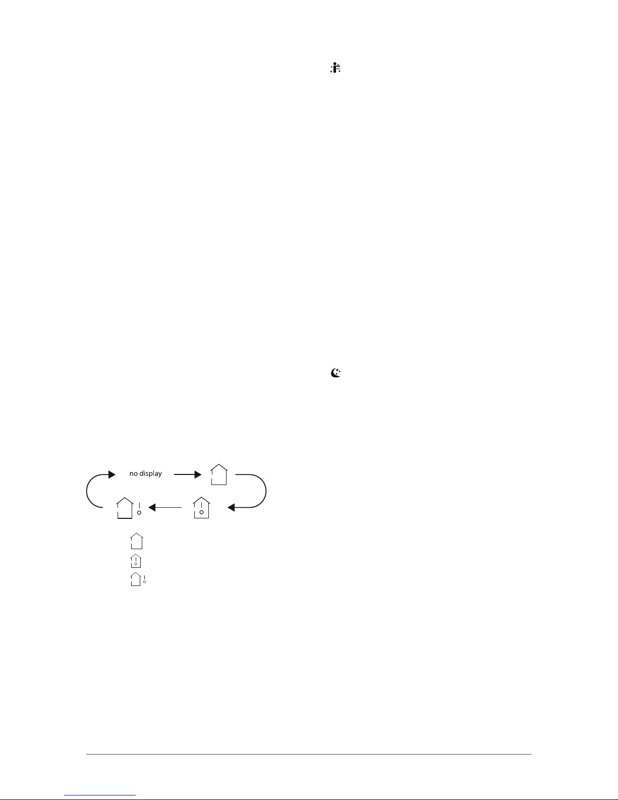
9. TEMP button
When pushing this button, you can choose the temperature you wish to see on the indoor unit display:
set temperature, indoor room temperature or outdoor temperature.
• When " " or “ no display” is displayed, the set temperature is shown.
• When "
• When "
" is displayed, indoor room temperature is shown.
" is displayed, current outdoor temperature is shown.
NOTE:
Current outdoor temperature is not available on all models. In that case, the set temperature is shown.
10 and 12. TIMER ON button and TIMER OFF button
This timer function allows you to program the unit while determining when it starts and when it ends.
Before using this function, make sure your unit is set on the right time.
Setting the starting time of the device:
1. Press TIMER ON button.
2. Press " + " or " - " button in order to set the starting time.
3. Press again TIMER ON to confirm time.
12
Page 13

Icon " ON " appears and remote control shows current time.
Setting the ending time of the device:
1. Press the TIMER OFF button.
2. Press the " + " or " - " button in order to set the ending time.
3. Press again TIMER OFF to confirm time.
Icon " OFF " appears and remote control shows current time.
To cancel this function, press the TIMER ON and/or TIMER OFF button and corresponding icons will
disappear.
NOTES:
• If only TIMER ON is set, the unit will work until you manually turn it off.
• If only TIMER OFF is set, the unit will not start again until you manually turn it on.
11. CLOCK button
Press this button to set time. Icon "
" on remote control will blink. Within the next 5 seconds, press
button " + " or " - " to set time. With every push on the button " + " or " - ", time increases or decreases by
one minute. Hold this either buttons for 2 seconds in order to change time faster. Press again the CLOCK
button to confirm the hour and come back to normal display.
NOTE:
Clock uses 24-hour mode.
13. TURBO button
When TURBO function is on, the unit operates at super high speed to achieve quick cooling or heating.
This function is available only in COOL (cooling) or HEAT (heating) mode.
When you press this button, icon "
" appears on the screen. Press the button again to cancel TURBO
function.
NOTE:
When TURBO function is activated, fan speed can’t be changed.
14. LIGHT button
Press that button to light the indoor unit display screen. When the light on the display screen is on, icon
"
" appears on the screen.
15. X-FAN button
Pressing this button in COOL or DRY mode, the icon "
" is displayed and the indoor fan will continue
operation for a few minutes in order to dry the indoor unit even though you have turned off the unit.
After energization, X-FAN OFF is defaulted. X-FAN is not available in AUTO, FAN or HEAT mode. This function indicates that moisture on evaporator of indoor unit will be blowed after the unit is stopped to avoid
mould.
• Having set X-FAN function on: After turning off the unit by pressing ON/OFF button indoor fan will
continue running for a few minutes at low speed. In this period, press X-FAN button to stop indoor fan
directly.
• Having set X-FAN function off: After turning off the unit by pressing ON/OFF button, the complete unit
will be off directly.
13
Page 14

SPECIAL FUNCTIONS
Child lock function
This function eliminates unwanted temperature adjustments and the use of different modes on the
device. Before activating it, make sure to have set the temperature as you like.
Press simultaneously " + " and " - " buttons to activate or deactivate the child lock function. When that
function is activated, icon "
Temperature display in °C or °F
When device is turned off (OFF), press simultaneously on " - " and MODE buttons to switch from °C or °F.
FREEZE PROTECT mode
During winter, FREEZE PROTECT mode allows to maintain room temperature at 8 °C (46 °F) when you are
not at home. When device is in HEAT (heating) mode, press simultaneously on CLOCK and TEMP buttons
to activate this function. Icon " $ " will be displayed. Press again simultaneously on CLOCK and TEMP
buttons to deactivate.
NOTES:
• In FREEZE PROTECT mode, fan speed is set by default to AUTO and cannot be adjusted.
• SLEEP and FREEZE PROTECT mode cannot be activated at the same time.
" is displayed on the remote control.
14
Page 15

REPLACING BATTERIES IN REMOTE CONTROL
1. Lightly press the " " and slide in the direction the arrow
is pointing to remove the back cover of the remote control
(as illustrated).
2. Remove the old batteries (as illustrated).
3. Insert two new " AAA " (1.5 V) dry batteries and make sure
the position of + and – is correct (as illustrated).
4. Put back the cover (as illustrated).
NOTES:
• During operation, point the remote control at the receiving window on the indoor unit.
• The distance between the remote control and receiving window should not be more than
26.25 ft. (8 m) and there should be no obstacle between them.
• The remote control should be placed 3.3 ft. (1 m) away from TV or Audio sets.
• The signal can be easily interfered in a room where there is a fluorescent lamp or wireless phone;
the remote control should be near the indoor unit when operating.
• If the remote control does not operate normally, please take out the batteries and reinsert them
after 30 seconds. If it is still not working, replace the batteries.
• When replacing batteries, use only new and identical ones (same brand).
• When you do not use the remote control for a long time, take out the batteries.
15
Page 16

EMERGENCY OPERATION
If the remote control is lost or damaged, please use AUX button to turn on or turn off the appliance.
As illustrated, open the panel, press the AUX button to turn on or turn off the device.
When it is turned on, it will operate under AUTO mode.
panel
AUX button
WARNING
Use insulated object other than metal to press the AUX button.
16
Page 17

MAINTENANCE
CLEANING AND MAINTENANCE
WARNING
• Turn off the unit and disconnect the power before cleaning to avoid electric shock.
• Do not wash the unit with water to avoid electric shock.
• Do not use volatile liquid to clean the unit.
Cleaning the surface of indoor unit
When the surface of indoor unit is dirty, it is recommended to use a softdry cloth or lightly moistened
with water to wipe it.
NOTICE
Clean filter
1. Open panel
Open the panel into a certain angle as illustrated (less than 60°, do not force the panel).
2. Remove filter
Remove the filter as illustrated.
Do not remove the panel when cleaning it.
3. Clean filter
Use a vacuum or water to clean the filter.
When the filter is very dirty, use water (below 45 °C) to
clean it, and then put it in a shady and cool place to dry.
4. Install filter
Install the filter and then close the panel cover tightly.
WARNING
• The filter should be cleaned every three months. If the unit operates in a highly dusty environment,
cleaning frequency should be increased.
• After removing the filter, do not touch fins to avoid injury or damage the unit.
• Do not use fire or hair dryer to dry the filter to avoid deformation or fire hazard.
17
Page 18

Checking before usage
1. Check that air inlets and air outlets are not blocked.
2. Check if circuit breaker and connection are in good condition.
3. Check that filters are clean.
4. Check that drainage pipe is not damaged or blocked.
Checking after usage
1. Disconnect power supply.
2. Clean filters and indoor unit panel.
3. Check whether mounting bracket for outdoor unit is damaged or corroded.
If so, please contact the dealer.
Notice for recovery
1. Many packing materials are recyclable. Please dispose of them in appropriate recycling bin.
2. If you want to get rid of the device, please contact a local recycling center for the correct
disposal method.
18
Page 19

MALFUNCTION
MALFUNCTION ANALYSIS
Please check below items before asking for servicing. If the malfunction still cannot be eliminated, please
contact a qualified person.
Phenomenon Items to check Solution
Cut the power supply off and put the
power back after about 3 minutes,
and then turn on the unit again.
Signal receiving distance is
26.25 ft. (8 m).
Remove obstacles.
Select proper angle and point
the remote control at the receiving
window on indoor unit.
Check the batteries. If the
battery charge level is too low,
please replace them.
Check if remote control is damaged.
If so, replace it.
Bring the remote control
close to the indoor unit.
Turn off the fluorescent lamps
and then try it again.
Eliminate obstacles.
After reaching set temperature,
indoor unit will stop blowing out air.
In heating mode, in order to prevent
blowing out cold air, indoor unit will
start a few minutes after the unit has
been turned on, which is normal.
Ask a qualified person to replace
circuit break or replace wiring.
Wait for 3 minutes, and then turn on
the unit again.
Reset the functions
Press the “LIGHT” button on the
remote control to light the indoor
unit display screen.
Indoor unit cannot
receive remote
control signal or
remote control does
not work.
No air flow
from indoor unit.
Appliance cannot
operate.
Indoor unit display
screen doesn’t work
Is there severe interferences (such as
static electricity, unstable voltage)?
Is the remote control within the
signal receiving distance?
Is there any obstacle between the
unit and the remote control?
Is the remote control pointing at the
receiving window of the indoor unit?
Is the remote control display fuzzy
or there is no display at all ?
No display when operating
the remote control?
Are there fluorescent lamps in the
room?
Are air inlet or air outlet of indoor
unit blocked?
Under heating mode, has indoor
temperature reached set
temperature?
Has the heating mode been
just turned on?
Is there a power failure? Wait until power resumes.
Circuit break trips off?
Has the unit been turned on immediately after being turned off?
Are the function setting on the
remote control correct?
Is the “LIGHT” function deactivated?
19
Page 20

Phenomenon Items to check Solution
This is because indoor air is
Mist is emitted from
indoor unit air outlet.
Are indoor temperature and
humidity level high?
cooled rapidly. After a while,
indoor temperature and humidity
level will decrease and mist will
disappear.
Temperature cannot be adjusted
Set temperature
cannot be adjusted.
Air cooling (heating)
is not efficient.
Is the unit operating under AUTO
mode?
Does your required temperature
exceed the set temperature range?
Is voltage too low?
Is filter dirty? Clean the filter.
Is the set temperature in proper
range?
under AUTO mode.
Please switch the operationmode
if you need to adjust temperature.
Set temperature range:
16 °C to 30 °C (61 °F to 86 °F).
Wait until the voltage comes back
to normal.
Adjust temperature within proper
range.
Are doors and windows open? Close doors and windows.
Odours are emitted.
Is there an odour source in the room,
such as furniture or cigarette.
Is the heat exchanger dirty? Have it cleaned by a specialist.
Eliminate the odour source.
Is the filter dirty? Clean the filter.
Appliance suddenly
operates abnormally.
Outdoor unit emits
vapor.
Water flowing noise.
There may be interferences, such as
thunder, wireless devices, etc.
Is the unit in heating mode?
Has the air conditioner just
been turned on and off?
Cut the power supply off and put
the power back. Then turn on the
unit again.
During defrosting under heating
mode, it may produce vapor,
which is normal.
The noise is the sound of refrigerant
flowing inside the unit, which
is normal.
This is the sound of friction caused
Cracking noise.
Has the air conditioner just
been turned on and off?
by expansion and/or contraction
of panel or other parts due to
temperature changes.
20
Page 21

ERROR CODES
When appliance status is abnormal, temperature indicator on indoor unit will blink and display corresponding error code. Please refer to list below for identification of error code.
Error
code
C5 Please contact a qualified person for service.
E2 Verify if filter needs to be cleaned. Make sure nothing is blocking air inlet or outlet.
E5 It can be eliminated after restarting the unit. If not, please a qualified person for service.
E6 It can be eliminated after restarting the unit. If not, please contact a qualified person
E7
E8 It can be eliminated after restarting the unit. If not, please contact a qualified person
F0 It can be eliminated by disconnecting power at the main panel. Wait 10 minutes before
F1 Please contact a qualified person for service.
F2 Please contact a qualified person for service.
H1 This code indicates that device is in defrosting mode. When defrosting cycle is finished,
H6 It can be eliminated after restarting the unit. If not, please contact a qualified person
What to do?
Restart device. If not, please contact a qualified person for service.
for service.
Multizone heat pumps – There is a demand for cooling and heating at the same time.
The indoor unit that sent the signal first has priority. The other indoor unit(s) are waiting
for the end of the heating or cooling cycle, as the case may be, to enter the other mode.
for service.
energizing. If the error code remains, please contact a qualified person for service.
code will disappear.
for service.
U8 It can be eliminated after restarting the unit. If not, please contact a qualified person
for service.
Note: If there are other error codes, please contact a qualified person for service.
WARNING
When below phenomenon occurs, please turn off the unit and disconnect power immediately,
then contact a qualified person for service:
• There is an unusual sound during operation.
• Circuit break trips off frequently.
• Device generates a burning smell.
• Indoor unit is leaking.
CAUTION
• Do not repair or refit the appliance by yourself.
• If the appliance operates under abnormal conditions, it may damage the unit, cause electric shock
or fire hazard.
21
Page 22

PREPARATION BEFORE INSTALLATION
REQUIRED INSTALLATION CLEARANCE DISTANCES DIAGRAM
At least 15 cm
Space to the ceiling
Space to the wall
Space to the wall
At least 15 cm
At least 15 cm
At least 300 cm
Space to the obstruction
At least 30 cm
At least 50 cm
Space to the obstruction
At least 183 cm
Space to the floor
Space to the obstruction
At least 30 cm
Space to the wall
Space to the obstruction
22
At least 200 cm
At least 50 cm
Space to the
obstruction
Drainage pipe
Page 23

TOOLS REQUIRED FOR INSTALLATION
• Level meter
• Screwdrivers
• Impact drill
• Drill head
• Pipe expander
• Torque wrench
• Open-end wrench
• Pipe cutter
• Leakage detector
• Vacuum pump
• Manometer
• Multimeter
• Inner hexagon spanner
• Measuring tape
NOTICE
Contact a qualified person for installation.
SELECTION OF INSTALLATION LOCATION
Basic requirements
Installing the unit in the following places may cause malfunction. If it is unavoidable, please consult
a qualified person:
• A place with strong heat sources, vapors, flammable or explosive gas or volatile objects spread in
the air.
• A place with high-frequency devices (such as welding machine, medical equipment).
• A place near coastal regions.
• A place with oil or fumes in the air.
• A place with sulphurous gas.
• Other places with special environment.
• In a laundry room, near a bath, shower or swimming pool.
Indoor unit
• There should be no obstruction near air inlet and air outlet.
• Select a location where the condensation water can be dispersed easily and will not affect people.
• Select a location which is convenient to connect the outdoor unit and which is the closest possible
to the power supply.
• Select a location which is out of reach for children.
• The location should be able to withstand the weight of indoor unit and will not increase noise
and vibration.
• Make sure that the installation follows the requirement of clearance distance diagram.
• Do not install the indoor unit right above an electric appliance.
• Please try your best to keep the unit away from fluorescent lamps.
23
Page 24

Outdoor unit
• Select a location where the noise and outflow air emitted by the outdoor unit will not affect
neighborhood.
• The location should be well ventilated and dry, where the outdoor unit won’t be exposed directly
to sunlight or strong wind.
• The location should be able to withstand the weight of outdoor unit.
• Make sure that the installation follows the requirement of clearance distance diagram.
• Select a location which is out of reach for children and far away from animals or plants. If it is
unavoidable, please add a fence for safety purpose.
• Do not install the outdoor unit opposite to an air outlet. Eg.: dryer outlet, kitchen hood, etc.
REQUIREMENTS FOR ELECTRICAL CONNECTION
Safety precautions
• Must follow the electric safety regulations when installing the unit.
• According to the local safety regulations, use qualified power supply circuit and circuit break.
• Make sure the power supply matches with the requirement of the device. Unstable power supply
or incorrect wiring may cause malfunction and damage the unit or fire hazard.
• Properly connect the live wire, neutral wire and grounding wire.
• Cut off the power supply before proceeding any work related to electricity.
• Do not put through the power before finishing installation.
• The temperature of refrigerant circuit will be high, please keep the interconnection cable away
from the copper tube.
• The appliance shall be installed in accordance with national wiring regulations.
Grounding requirements
• The heat pump is a first class electric appliance. It must be properly grounded by a qualified person
with specialized grounding device. Please make sure it is always grounded effectively, otherwise
it may cause electric shock.
• The yellow-green wire in the appliance is the grounding wire, which cannot be used for other
purposes.
• The grounding resistance should comply with national electric safety regulations.
• An all-pole disconnect switch having a contact separation of at least 3mm in all poles should be
connected in fixed wiring.
24
Page 25

INSTALLATION
INSTALLATION OF INDOOR UNIT
Step 1: Choosing installation location
• Recommend the installation location to the customer and then confirm it with the customer.
Step 2: Install wall-mounting frame
• Hang the wall-mounting frame on the wall; adjust it in horizontal position with the level meter
and then point out the screw fixing holes on the wall.
• Drill the screw fixing holes on the wall with the impact drill (the drill head specification should
be the same as the plastic anchor) and then put the plastic anchors in the holes.
• Fix the wall-mounting frame on the wall with tapping screws (ST4.2X25TA) and then check if the frame
is firmly installed by pulling the frame. If a plastic anchor is loose, drill another fixing hole nearby.
Step 3: Open piping hole
• Choose the position of piping hole according to the direction of outlet pipe. The position of piping
hole should be a little lower than the wall-mounting frame, as shown below.
12K 18K
Wall
Mark in the middle of it
Space
to the
wall
above
150 mm
Left
(Rear piping hole) (Rear piping hole)
Level meter
Space
to the
above
150 mm
Wall
wall
Right
Wall
(Rear piping hole) (Rear piping hole)
Mark in the middle of it
Space
to the
wall
above
150 mm
Left
Level meter
24K
Space
to the
wall
above
150 mm
Right
Wall
Wall
Mark in the middle of it
Space
to the
wall
above
150 mm
Left
(Rear piping hole) (Rear piping hole)
Level meter
• Open a piping hole with a diameter of Φ55 mm or Φ70 mm depending on selected outlet pipe.
In order to drain efficiently, slant the piping hole on the wall slightly downward to the outdoor
side with a gradient of 5° to 10°.
Space
to the
wall
above
150 mm
Right
Wall
NOTES:
• Pay attention to dust and take relevant safety measures
when opening the hole.
• The plastic anchors are not provided and should
be bought locally.
Interior Exterior
5-10
25
Page 26

Step 4: Outlet pipe
• The pipe can be led out to the right,
rear right, left or rear left.
• When direction of the pipe has been selected,
please cut off the corresponding hole on the
bottom case.
left rear left
right
rear right
Step 5: Connect the pipe of indoor unit
• Aim the pipe joint at the corresponding bell
mouth.
• Pre-tighten the union nut with hand.
• Place the open-end wrench on the pipe joint
and place the torque wrench on the union nut.
Tighten the union nut with torque wrench.
Adjust the torque force by referring to the
following table.
open-end wrench
union nut
left
cut off
the hole
pipe joint
Hex nut diameter
Φ 6 15~20
Φ 9.52 30~40
right
union nut
pipe
Tightening torque
(N-m)
torque wrench
pipe
indoor pipe
• Wrap the indoor pipe and joint of connection
pipe with insulating pipe, and then wrap it with
tape.
Step 6: Install drain hose
• Connect the drain hose to the outlet pipe
of indoor unit.
drain hose
outlet
pipe
Φ 12 45~55
Φ 16 60~65
Φ 19 70~75
insulating pipe
• Bind the joint with tape.
drain hose
outlet pipe
tape
26
Page 27

NOTICE
• Add insulating pipe around the indoor drain hose
in order to prevent condensation.
• The plastic anchors are not provided.
Step 7: Connect wire of indoor unit and repositioning of the ambient sensor
panel
• Open the panel, remove the screw on the
wiring cover and then take the cover off.
screw
wiring cover
• Take the ambient temperature sensor in the
electronic board box and insert it in the groove
as per above image.
• Make the power connection wire go through
the cable-cross hole at the back of indoor unit
and then pull it out from the front side.
cable-cross
hole
drain hose
insulating pipe
groove
electronic board
box
power connection
wire
• Remove the wire clip; connect the power connection wire to the wiring terminal according to the color;
tighten the screw and then fix the power connection wire with wire clip. After finishing wiring, clamp
the grounding wire (yellow-green wire) into the wire-crossing groove as shown in the following figure,
in order to avoid pressing the wire when closing the electric box cover.
Indoor unit connection
09-12K
N(1)
L1
(N)1
3
2
L2
32
outdoor unit
09-12K (for some model)
N(1)
White
(Blue)
18-24K
N(1)
(N)1 32
3
2
Black
2
Red
(Brown)
3
L2 GL1
outdoor unit
Green
(Yellow
-Green)
Note: this wiring diagram is for reference only, please always refer to the one on the actual unit.
• Put wiring cover back and then tighten the screw.
outdoor unit
27
Page 28

• Close the panel.
Notes:
• All wires of indoor and outdoor unit should be connected by a qualified person.
• If the length of power connection wire is insufficient, please contact your dealer for a new one.
Do not extend the wire by yourself.
• A circuit break must be installed in the line. The air switch should be all-pole parting and the contact
parting distance should be more than 3 mm.
Step 8: Bind up pipes
• Bind up the connection pipe, power cord and drain hose with the band.
connection
pipe
indoor power cord
• Reserve a certain length of drain hose and power cord for installation when binding them.
drain hose
band
indoor unit
indoor and outdoor
band
power cord
drain hose
gas
pipe
When binding to a certain degree, separate the indoor power and then separate the drain hose.
• Bind them evenly.
• The liquid pipe and gas pipe should be bound separately at the end.
Notes:
• The power cord and control wire cannot be crossed or winded.
• The drain hose should be bound at the bottom.
Step 9: Hang the indoor unit
• Put the bound pipes in the wall pipe and then make them pass through the wall hole.
• Hang the indoor unit on the wall-mounting frame.
liquid pipe
• Stuff the gap between pipes and wall hole with sealing gum.
• Fix the wall pipe.
• Check if the indoor unit is installed firmly to the wall.
Note:
28
Page 29

indoor
wall pipe
outdoor
sealing gum
• Do not bend the drain hose excessively in order to prevent blocking.
INSTALLATION OF OUTDOOR UNIT
Step 1: Fix the support of outdoor unit
(select it according to the actual installation situation)
• Select installation location according to the house structure.
upper hook
lower hook of
wall-mounting frame
• Fix the support of outdoor unit on the selected location with expansion
screws.
Notes:
• Take sufficient protective measures when installing the outdoor unit.
• Make sure the support can withstand at least four times the unit weight.
• The outdoor unit should be installed at least 3 cm above the floor in
order to install drain joint.
• Expansion screws needed per type of unit :
Cooling capacity
BTU/hr (W)
No Number of screws
9000 (2637) 6
12000 (3516) 6
18000 (5274) 8
24000 (7032) 8
Step 2: Install drain joint
• Connect the outdoor drain joint into the hole
on the chassis, as shown in the picture below.
at least 3 cm above the floor
• Connect the drain hose into the drain vent.
drain vent
drain hose
chassis
outdoor drain joint
29
Page 30

Step 3: Fix outdoor unit
foot holes
• Place the outdoor unit on the support.
• Fix the foot holes of outdoor unit with bolts.
foot holes
Step 4: Connect indoor and outdoor pipes
• Remove the screw on the right handle of outdoor unit and then remove the handle.
screw
handle
• Remove the valve cap and align the pipe joint on the flared orifice of the pipe.
liquid pipe
liquid
valve
gas pipe
gas valve
• Pre-tighten the union nut by hand.
pipe joint
union nut
• Tighten the union nut with torque wrench by referring to the sheet below.
Hex nut diameter
Tightening torque
(N-m)
Φ 6 15~20
Φ 9.52 30~40
Φ 12 45~55
Φ 16 60~65
Φ 19 70~75
30
Page 31

Step 5: Wiring of the unit
• Remove the wire clip; connect the power connection wire and signal control wire to the wiring
terminal according to the color; fix them with screws.
Outdoor unit connection
09-12K
N(1)
3
2
09-12K (for some model)
3
2
N(1) L N
L1
N(1)
L2
L2
L1
POWER
3
2
indoor unit indoor unit
N(1)
3
2
N
L
POWER
18-24K (for some model)18-24K
N(1) L1 GL2
N(1)
3
2
indoor unit
L1
L2
POWER
Green
(Yellow
-Green)
3
2
N(1) L1 GL2
White
(Blue)
indoor unit
Black
Red
(Brown)
Black
(Brown)
L1
POWER
White
(Blue)
Green
(Yellow
-Green)
L2
3
2
Note: this wiring diagram is for reference only, please always refer to the one on the actual unit.
• Fix the power connection wire and signal control wire with wire clip.
Notes:
• After tightening the screw, pull the power cord slightly to check if it is solid.
• Never cut the power connection wire to extend or shorten it.
Step 6: Pipe arrangement
• The pipes should be placed along the wall, slightly
bent and if possible be hidden. The minimum
bending semi diameter is 10 cm.
• If the outdoor unit is higher than the wall hole,
you must set a U-shaped curve in the pipe before
pipe goes into the house, in order to prevent rain
from getting in.
U-shaped curve
wall
drain hose
31
Page 32
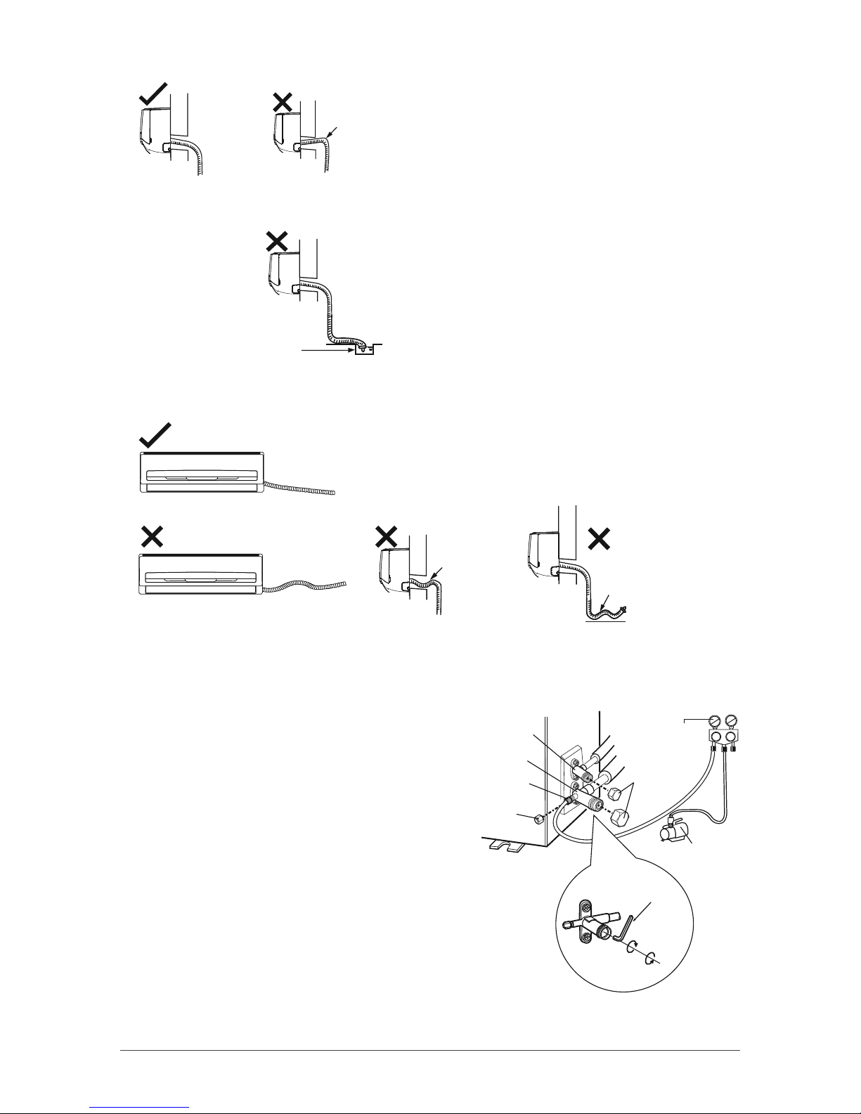
• The through-wall height of drain hose shouldn’t be higher than the outlet pipe hole of indoor unit.
The drain hose can’t raise
upwards.
• For efficient drainage, the water outlet should not be submerged.
The water outlet can’t be
placed in the water.
• Slant the drain hose slightly downwards; the drain hose can’t be curved, raised, wavy, etc.
The drain hose must be straightened.
The drain hose can’t be wavy.
VACUUM PUMPING
• Remove the valve caps on the liquid valve and
gas valve and the nut of refrigerant charging
vent.
• Connect the manometer charging hose to
the refrigerant charging vent of gas valve and
then connect the other charging hose to the
vacuum pump.
• Open the manometer completely and operate
for 10 to 15 minutes to check if the pressure of
manometer remains at -0.1 MPa.
• Close the vacuum pump and maintain this status for
1 to 2 minutes to check if the pressure remains at -0.1 MPa.
If the pressure decreases, there may be leakage.
• Open the liquid valve and gas valve completely with inner
hexagon spanner and remove the manometer.
charging vent
nut of refrigerant
charging vent
liquid valve piezometer
gas valve
refrigerant
valve cap
vacuum pump
inner hexagon
spanner
close
open
Lo Hi
• Tighten the screw caps of valves and refrigerant charging vent.
32
Page 33

Note:
Using a micro gage, bring the vacuum value down to at least 500 microns and make sure the value
remains stable for at least 10 minutes after the pump has stopped. If the value increase and doesn't stay
below 500 microns, there is a leak in the system.
LEAKAGE DETECTION
• With a leakage detector, check if there is leakage.
• If leakage detector is not available, please use soapy water for leakage detection. Apply soapy water at
the suspected position and leave it there for 3 minutes. If there are bubbles coming out of this position,
there is a leak.
CHECKING AFTER INSTALLATION
Check the following items after finishing installation:
Items to check Possible malfunction
Has the unit been installed solidly? The unit may drop, shake or emit noise.
Have you done the refrigerant leakage test? It may cause insufficient cooling (heating) capacity.
Is heat insulation of pipeline sufficient? It may cause condensation and water dripping.
Is water drained well? It may cause condensation and water dripping.
Is the voltage of power supply according to the
voltage marked on the nameplate?
Are electric wiring and pipes installed correctly? It may cause malfunction or damaging the parts.
Is the unit grounded securely? It may cause electric leakage.
Does the power wire follow the specifications? It may cause malfunction or damaging the parts.
Is there any obstruction in the air inlet and
outlet?
Are dust and installation debris removed? It may cause malfunction or damaging the parts.
Are gas valve and liquid valve of connection
pipe completely opened?
It may cause malfunction or damaging the parts.
It may cause insufficient cooling (heating) capacity.
It may cause insufficient cooling (heating) capacity.
33
Page 34

OPERATION TEST
1. Before operation test
• Ensure that the customer is satisfied.
• Inform the customers about the important notes of the appliance.
2. Operation test
• Put through the power, press the ON/OFF button on the remote control to start the unit.
• Press MODE button to select AUTO, COOL, DRY, FAN or HEAT to check whether the operation is normal
or not.
• If the ambient temperature is lower than 16 °C, the appliance will not work in COOL (cooling) mode.
3. Operating pressure test
• In COOL or HEAT mode, set the temperature to the maximum set point (30 °C or 86 °F).
• Press the TURBO button to activate the fan TURBO speed.
• Wait until the compressor has reached its full speed (15 to 30 minutes).
• Once full speed is reached, take the operating pressure as well as indoor and outdoor temperature.
• Note your results in the table below and keep it for future reference.
Results of the operating pressure test
Operating pressure
Indoor temperature
Outdoor temperature
4. Other measures to consider
• Take the amperage reading with the unit in TURBO, HEAT and CAOOL mode. Wait until the amperage is
stable before noting the results in the table below.
Tests Results
Amperage reading in TURBO mode
Amperage reading in HEAT mode
Amperage reading in COOL mode
Duration of the vacuum
Vacuum value when stopping the pump
Value 15 minutes after stopping the pump
Reading of the micron gage
34
Page 35

OTHER CONSIDERATIONS
CONFIGURATION OF CONNECTION PIPE
• Standard length of connection pipe: 25 ft. (7.5 m).
• Minimum length of connection pipe: 10 ft. (3 m).
• Maximum length of connection pipe and maximum height difference:
Cooling capacity
BTU/hr (W)
9000 (2637) 49 (15) 33 (10)
12000 (3516) 66 (20) 33 (10)
18000 (5274) 82 (25) 33 (10)
24000 (7032) 82 (25) 33 (10)
Additional refrigerant liquid and refrigerant charge required after extending connection pipes
• The calculation method of additional refrigerant charge (on the basis of liquid pipe) is:
Additional refrigerant charge (oz) = extended length of liquid pipe (ft.) x 0.2
• Based on the length of standard pipe and depending on pipe diameter, add refrigerant as per
following chart.
Additional refrigerant charge for R410A
Diameter of connection pipe Outdoor unit throttle
Liquid pipe
(mm)
Φ 6 Φ 9.52 ou Φ 12 15 20
Gas pipe
Maximum length
of connection pipe
(mm)
ft. (m)
Cooling only
(g/m)
Maximum height
difference
ft. (m)
Cooling and heating
(g/m)
Φ 6 ou Φ 9.52 Φ 16 ou Φ 19 15 50
Φ 12 Φ 19 ou Φ 22.2 30 120
Φ 16 Φ 25.4 ou Φ 31.8 60 120
Φ 19 - 250 250
Φ 22.2 - 350 350
35
Page 36

PIPE EXPANDING METHOD
Notes:
• Improper pipe expanding is the main cause of refrigerant leakage.
• Use mechanical joints only. Do not weld on the pipes.
• Please expand the pipe according to the following steps:
1. Cut the pipe
• Confirm the pipe length according to the
distance between indoor and outdoor unit.
• Cut the pipe with pipe cutter.
pipe
pipe cutter
leaning uneven burr
2. Remove the burrs
• Remove the burrs with a sharper and
prevent the burrs from getting into the pipe.
pipe
shaper
5. Expand the port
• Expand the port with an expander.
hard
expander
mold
pipe
Note:
"A" varies according to the diameter, please refer to
the chart below:
Outer diameter
(mm)
A (mm)
Max Min
Φ 6 - 6.35 (1/4’’) 1.3 0.7
Φ 9.52 (3/8’’) 1.6 1.0
Φ 12 - 12.7 (1/2’’) 1.8 1.0
Φ 15.8 - 16 (5/8’’) 2.4 2.2
downwards
3. Put on suitable insulating pipe
4. Put on the union nut
• Remove the union nut on the indoor connection
pipe and outdoor valve; install the union nut on
the pipe.
union pipe
pipe
36
6. Inspection
• Check the quality of the expansion. If the surface
is not smooth, repeat the previous steps.
smooth surface
improper expanding
the length is equal
leaning crackdamaged
surface
uneven
thickness
 Loading...