

Page 1
You must provide an overload protection and disconnect as required.
RT850T - Installation Instructions
Electric Heating Solid State Relay with Built-in 24 V Transformer
RT850T
Application
The RT850T Solid State Relay is designed to control a line voltage
resistive load from a 24 V control signal or dry contact.
With its unique thermal bridge design, the RT850T allows for
efficient heat dissipation and also features an LED indicator for
visual confirmation of product switching.
This electronic switching relay provides fast commuting operation;
when the RT850T is combined with a short-cycled thermostat
(15 seconds), it provides more precise temperature control.
The RT850T has a built-in 24 V transformer and is compatible with
3-wire (R,C,W) thermostats as well as 2-wire mechanical and
battery-operated thermostats. Main applications include control of
electric heating systems.
Installation
The RT850T must be mounted where ambient temperature is from
-4°F to 140°F (-20°C to 60°C).
The RT850T must be mounted on a 4 x 4 electrical box for proper
operation.
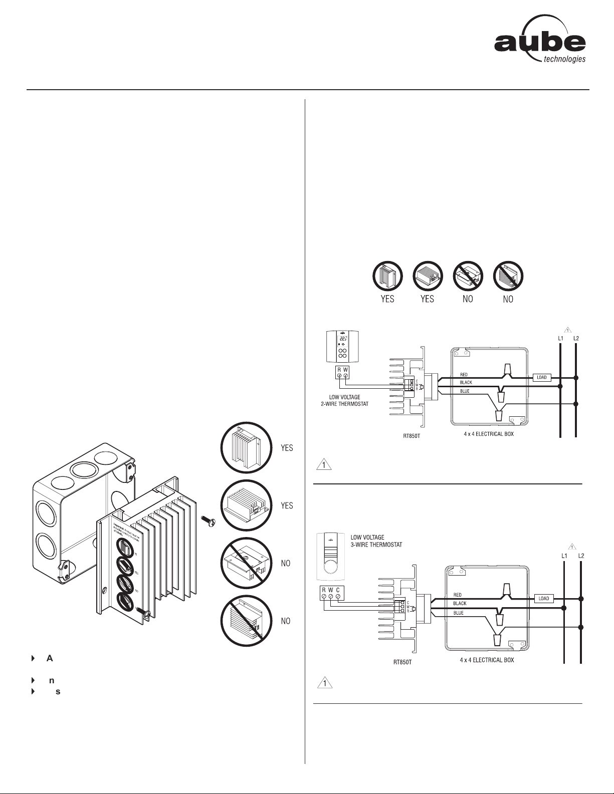
WARNING: The relay must be mounted so the heatsink’s fins are
vertical or facing upwards. You should also provide an empty space
above the heatsink so the warm air can exit the heatsink area.
Disregarding this warning may result in improper operation. Refer to
diagrams below for correct mounting guidelines.
p Once mounting and wiring have been completed, return power
to the heating system.
q Increase thermostat temperature in order to activate the relay
(LED should be ON). Allow system operation long enough to
proof installation.
r Once installation has been proofed, set temperature to normal
operating setpoint.
Typical Wiring Diagrams
NOTE: Relay is shown sideways for a general overview of wiring
and connections. The RT850T must be positioned as follows:
Ͽ
All wiring must comply with national and local electrical
code regulations.
Ͽ
Installation should be carried out by an electrician.
Ͽ
Disconnect power supply before installing the relay to prevent electrical shock.
n Wire the relay and connect according to typical wiring diagrams
(refer to figures 1 & 2).
o Secure relay to the electrical box using the two mounting holes.
You must provide an overload protection and disconnect as required.
Figure 1: Connection to a 2-wire low voltage thermostat
Figure 2: Connection to a 3-wire low voltage thermostat
1/2 400-274-004-B
Page 2
Electrical Specifications
Technical Support
Ensure ratings are suitable for your application.
Voltage (VAC) 208 240 277 347
Resistive load (A) 23
Control signal 24 VAC / 40 mA
Guaranteed OFF signal
Transformer ratings: 24 VAC / 1.2 VA / Class 2
Ambient operating temp.: -4°F to 140°F (-20°C to 60°C)
Ambient storage: -40°F to 175°F (-40°C to 80°C)
Humidity limits: 0 to 95% non-condensing
Net weight: 1 lb. 3 oz. (552 g)
Terminal wire size: 12 AWG
Certification:
Voff
≤ 5 VAC
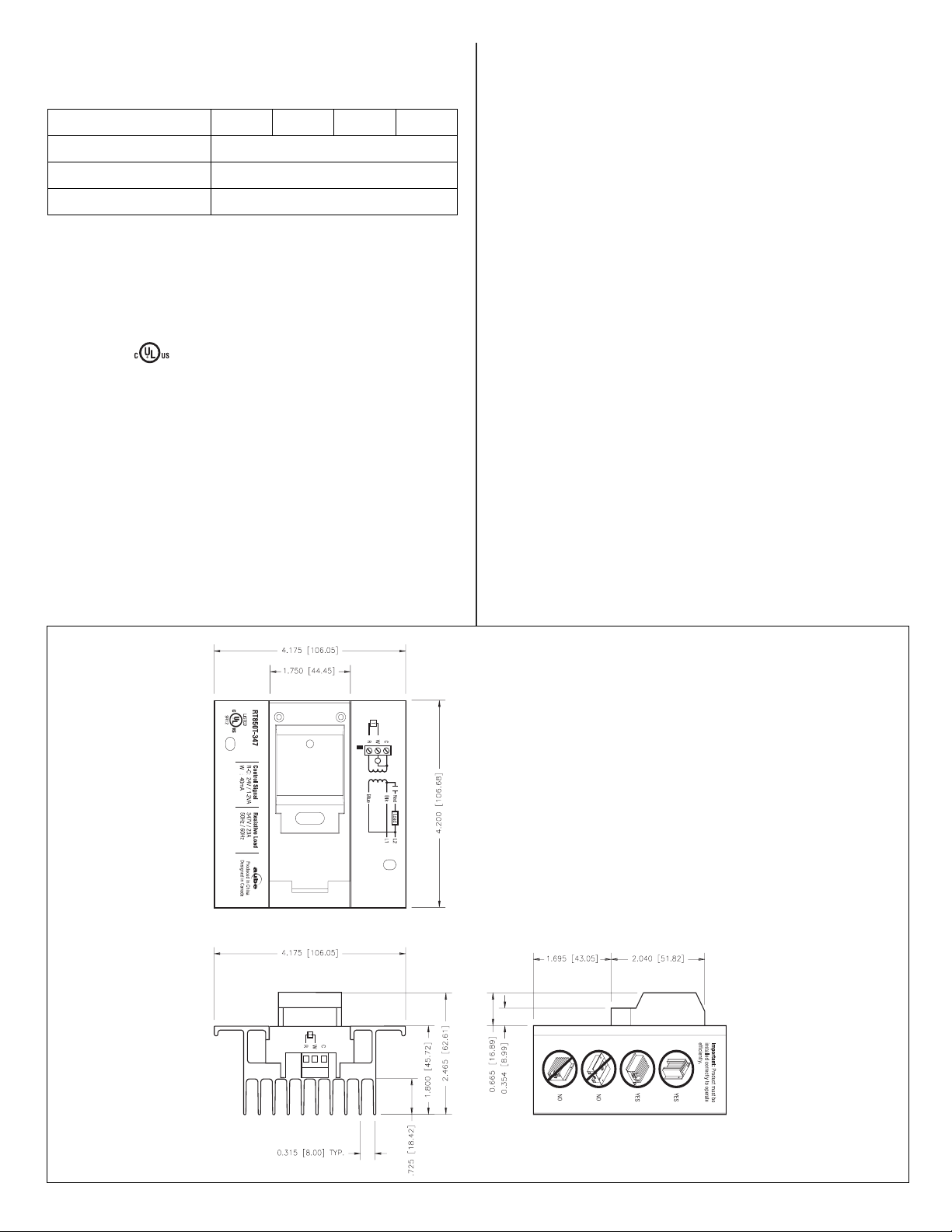
RT850T Dimensions
If you have any questions concerning the installation of the
RT850T relay, call our technical support team at:
Phone: Montreal area: (450) 358-4600
Canada / U.S.: 1-800-831-AUBE
Fax: (450) 358-4650
Email: service@aubetech.com
Monday to Friday from 8:30 AM to 5:00 PM EST.
For more information on our products, visit us at:
www.aubetech.com
(2823)
Warranty
AUBE TECHNOLOGIES INC. ONE (1) YEAR LIMITED WARRANTY
This product is guaranteed against workmanship defects for a one year
period following the initial date of purchase. During this period, AUBE
Technologies Inc. will repair or replace, at our option and without charge,
any defective product which has been used under normal conditions. The
warranty does not cover delivery costs and does not apply to products
poorly installed or randomly damaged following installation. This warranty
cancels and replaces any other manufacturer's express or implied warranty
as well as any other company commitment. AUBE Technologies Inc. cannot
be held liable for related or random damages following the installation of this
product. The defective product as well as the purchase invoice must be
returned to the place of purchase or mailed, prepaid and insured, to the
following address:
Aube Technologies Inc.
705 Montrichard
Saint-Jean-sur-Richelieu, Quebec, Canada J2X 5K8
Dimensions are expressed in INCHES [MM]
2/2 13/06/03 400-274-004-B
 Loading...