

Page 1
INSTALLATION MANUAL
Heating Cable for Concrete
OWC-M
series
Page 2

Page 3

Table of contents
1. Concrete heating cable OWC-M Series .......................................................................................................... 4
1.1 General information .................................................................................................................................. 4
1.2 Critical information ................................................................................................................................... 4
1.2.1 Required clearances ..................................................................................................................... 5
1.2.2 Always .......................................................................................................................................... 5
1.2.3 Never ............................................................................................................................................ 5
1.3 Identification of components .................................................................................................................... 6
1.3.1 Installation without reinforced concrete metal structure .............................................................. 6
1.3.2 Installation with reinforced concrete metal structure ................................................................... 7
2. Technical information ........................................................................................................................................ 8
2.1 Surface and power specifications for OWC-M products ......................................................................... 8
2.2 Insulation tests ......................................................................................................................................... 9
2.3 Cable resistance tests .............................................................................................................................. 9
2.4 Typical floor coverings .............................................................................................................................. 9
3. Heating options ............................................................................................................................................... 10
3.1 Floor control ........................................................................................................................................... 10
3.2 Ambient control with floor limit ............................................................................................................... 11
4. Installation guidelines ..................................................................................................................................... 12
4.1 Work coordination .................................................................................................................................. 12
4.2 Sub-floor preparation ............................................................................................................................. 13
4.3 Floor markings ........................................................................................................................................ 14
4.4 Power levels and measurement chart .................................................................................................... 14
4.5 Installation of concrete heating cables – OWC-M series ....................................................................... 15
4.5.1 Bypassing walls and obstacles .................................................................................................. 16
4.5.2 Installation of temperature sensor .............................................................................................. 18
4.5.3 Final steps while securing the installation .................................................................................. 18
4.6 Concreting .............................................................................................................................................. 19
4.7 Electrical connection .............................................................................................................................. 21
4.8 Putting into service ................................................................................................................................. 22
5. Control device .................................................................................................................................................. 23
5.1 Installation for floor control mode .......................................................................................................... 23
5.2 Installation for ambient control with floor limit mode ............................................................................. 23
5.3 List of control devices ............................................................................................................................ 23
6. Frequently asked questions (FAQ) ................................................................................................................. 25
7. Warranty ........................................................................................................................................................... 27
Page 4
1. Concrete heating cable OWC-M Series
WARNING!
1.1 General information
The concrete heating cables, series OWC-M include plastic mats of heating cables combined with an electrical
connection which can be connected to an electrical power source. This system is typically referred to as a
series heating cables set in accordance with the Canadian Electrical Code.
Installation must meet requirements specified by the following codes, when applicable:
- Canadian Electrical Code (CSA C22.1)
- American National Electricity Code (ANSI/NFPA 70)
- Any additional national or local installation code
In order to avoid any risk of electrical shocks,
always make sure the power from the electrical supply
circuit is turned off before handling the cables.
1.2 Critical information
- The OWC-M product is a system intended to heat a building either as a back-up heating system for a specific
room (floor control) or as the main heating system for a specific room (ambient control with floor limit).
Note: Installations using the OWC-M system for ambient control with floor limit only, see section 3.
- The OWC-M concrete heating cable system is designed and approved for interior heat (dry and humid
environments) as per specifications from the Canadian Electrical Code.
- The OWC-M concrete heating cable system is not designed for snow clearance applications or any other
exterior applications.
- The OWC-M concrete heating cable system can be installed under interior partitions, staircases, showers
and other sanitary fixtures, if clearances from drains and other fixed obstacles (fixed in concrete) are
adhered to and provided the system is used with a temperature sensor which regulates the temperature
of the concrete slab (see the following section for clearance guidelines).
- Floor temperatures will vary depending on floor insulation and characteristics. Maximum temperatures for
the floor and the room depend on various factors such as the type of insulation present in the room, the slab,
the number of windows, type of floor covering selected, etc...
- The OWC-M concrete heating cable system must be completely encased in concrete.
- The OWC-M concrete heating cable system must be installed by a certified electrician who is familiar with
the proper assessment of power strength requirements and risks associated with installation requirements,
as well as the construction techniques required for the installation and usability characteristics of the OWC-M
concrete heating cable systems.
- The OWC-M concrete heating cable system is but one step in the construction of a floor. Each building trade
involved is responsible for its own contract stipulations and must ensure that the work performed immediately
before their work segment begins has been completely and adequately finished, all according to good engineering practices. Everyone is a stakeholder in the installation process and the onus of responsibility
rests equally on every individual.
4
Page 5

1.2.1 Required clearances
The OWC-M concrete heating cable system is designed to generate 11 W/ft² (120 W/m²) of heat as per
factory installed specifications, with spacings of 6” (15 cm). Any spacing other than those specified in the
manual must first be approved by a specialist from Ouellet Canada Inc. OWC-M concrete heating cable
systems must be installed according to the following minimum distances:
- 3’’ (7.5 cm) between mat strips.
- 6’’ (15 cm) from the exterior perimeter of walls in the room to be heated.
- 3’’ (7.5 cm) from interior walls (if installed in ambient control by room).
- 6’’ (15 cm) from any drain or other fixed obstacle to be bypassed.
- 8’’ (20 cm) from any heating appliance anchored into the floor or coming into contact
with the floor (not applicable for convector-type appliances).
- 2’’ (5 cm) within the concrete surface.
- 0.5’’ (1.3 cm) from any open combustible surface.
1.2.2 Always
- Read the present instruction book in its entirety before installing the product.
- Install the OWC-M system together with an adequate and approved temperature control device.
- Use copper wires only.
- Perform tests required in accordance with the present instruction book and record findings on the
measurement chart.
- Make sure heating cables are completely encased in concrete.
- Make sure supply voltage is equivalent to the system’s rated voltage.
- Perform any repair work using the OWC repair kit available at your authorized Ouellet Canada Inc.
dealer.
- Consult Ouellet Canada’s specialists for any additional information.
- We recommend installing OWC-M systems in temperatures above 5 °C (40 °F).
- Metallic structures or materials used for supporting cables or on which cables are installed must
be grounded in compliance with the Canadian Electrical Code (CSA C22.1, section 10 and the
National Electrical Code).
- Installers must inspect and remove any damaged or defective heating cables before they are
covered up.
- Installers must provide markings on circuit-breakers (labels) that supply the electric circuit for
the heating cables.
1.2.3 Never
- Install OWC-M mat cable sections that are less than 3” (7.5 cm) from one another. This could create
overheating of the floor and cause damage.
- Reduce the length of heating cables or alter OWC-M cables in any way throughout their entire surface;
- Cross, overlap or layer heating cables (cables should never touch).
- Connect a product designed for 208/240V to 347V.
- Subject concrete cables to a bend radius inferior to 1.5” (38 mm).
- Install the temperature control device (thermostat or other) in a location which is accessible from
a shower or bathtub (the control device must be installed more than 1 meter away (3 feet, 4 inches)).
- Use metal fasteners for installing heating cables or the temperature sensor.
- Install the OWC-M heating cable system if the security seal has been broken.
5
Page 6
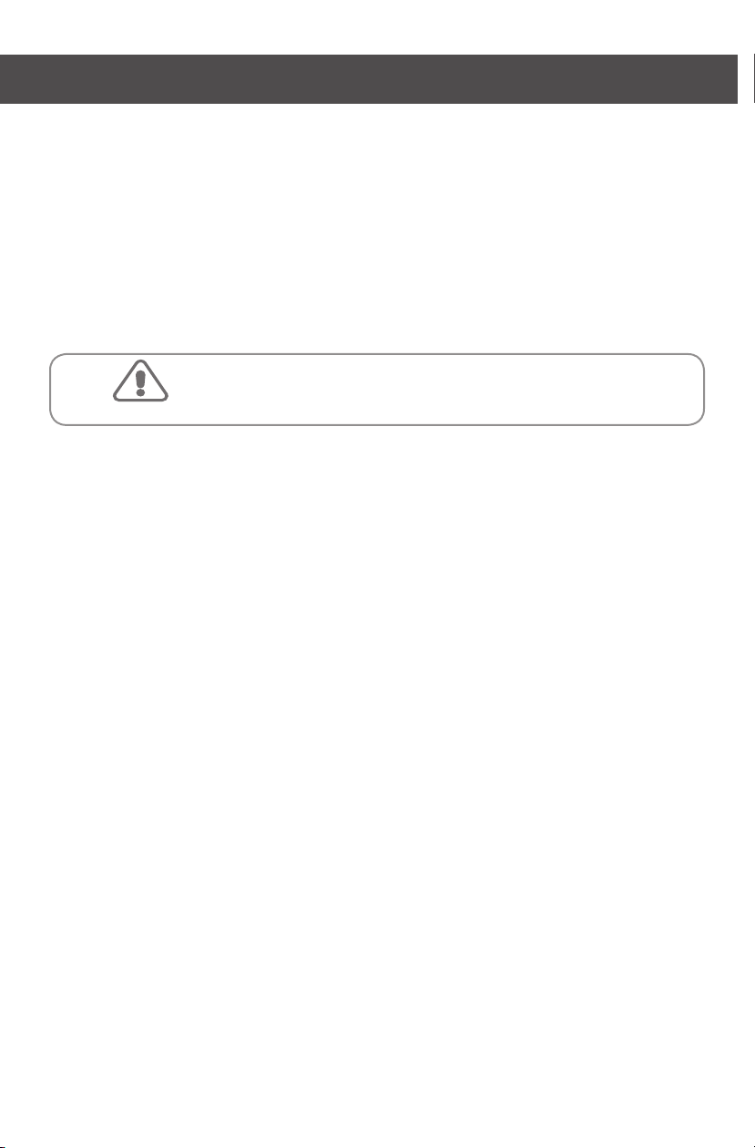
1.3 Identification of components
1.3.1 Installation without reinforced concrete metal structure
1 2 3 4
Thermostat
1
Cable ducts
for cold lead
Temperature
sensor
3’’
Spacing between
mats strips
2
7
3
4
6
5
6’’
6’’
5 6 7
Buffer zone and
6
floor fasteners
Clearance from drain
and fixed obstacle
Clearance from
exterior walls
Page 7
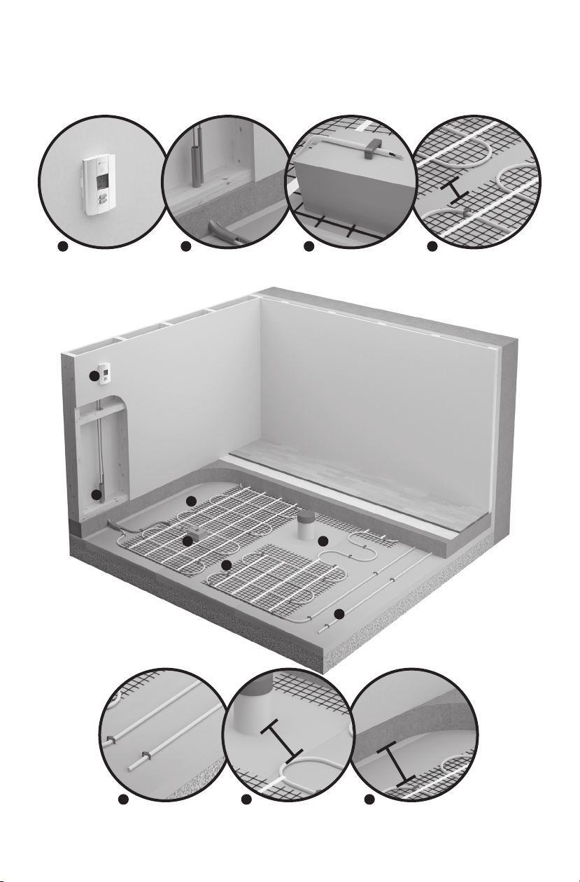
1.3.2 Installation with reinforced concrete metal structure
1 2 3 4
Thermostat
1
Cable ducts
for cold lead
Temperature
sensor
3’’
Spacing between
mats strips
2
5 6 7 8
Buffer zone and
floor fasteners
7
3
4
Clearance from drain
and fixed obstacle
6’’
5
8
Clearance from
exterior walls
6
6’’
Metallic structure for
reinforced concrete
7
Page 8
2. Technical information
Cold lead
WARNING!
2.1 Surface and power specifications for OWC-M products
Models OWC-M on mat 24’’ (0.6 m)
Product # Mat Covered Surface
240V/208V
OWC-M0300 - 28 2.3 12' 6" 3.8 300
OWC-M0500 - 46.5 4.3 20' 10" 6.4 500
OWC-M0700 - 65.5 5.8 29' 2" 8.9 700
OWC-M0950 - 89 8.2 39' 7" 12.1 950
OWC-M1300 - 121.5 11.6 54' 2" 16.5 1300
OWC-M1700 - 159 14.5 70' 10" 21.6 1700
OWC-M2000 OWC-M2007 187.5 17.4 83' 4" 25.4 2000
OWC-M2400 OWC-M2407 225 20.3 100' 30.5 2400
OWC-M2700 OWC-M2707 253 23.2 112' 6" 34.3 2700
OWC-M3000 OWC-M3007 281 26.0 125' 38.1 3000
OWC-M3400 OWC-M3407 318.5 29.0 141' 8" 43.2 3400
OWC-M3700 OWC-M3707 346.5 31.7 154' 2" 47.0 3700
OWC-M4000 OWC-M4007 375 34.6 166' 8" 50.8 4000
1
Does not represent the room surface but rather the area covered by the cable mat including 3” (7.5 cm) spacing between the mat strips
but excluding fixed elements to be bypassed and any other clearances required.
2
208V = 75% of wattage at 240V.
2
347V sq. ft. sq. m ft. m
1
Length of mat
Watts
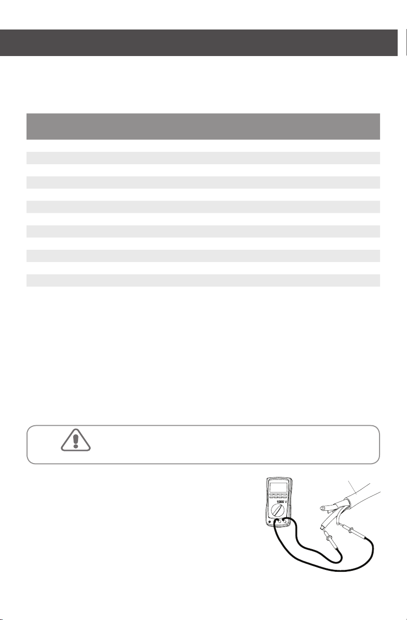
2.2 Insulation tests
Using a megohmmeter, measure the insulation resistance of OWC-M products at each stage of the installation
and note the values in the measurement chart on the electrical panel label available in the envelope provided
with the product.
Dangerous test. For the warranty to be applicable,
you must fill the measurement chart and ensure that all
8 measurements have been correctly recorded.
The system’s insulation resistance must be determined by
a certified electrician using the following method:
- With a calibrated megohmmeter only.
- Measure the insulation resistance at the loose end of the cold lead
between the phase conductor and the grounding.
- Record the value measured in the measurement chart.
- The value must be superior to 1,000,000 ohms.
- If the value is inferior to 1,000,000 ohms, postpone the work
and contact Ouellet Canada’s specialists at 1 800 463-7043.
8
Page 9

2.3 Resistance tests
Cold lead
WARNING!
WARNING!
Using a multimeter, measure the OWC-M cable resistance at each stage of the installation and note the values
in the measurement chart on the electrical panel label available in the envelope provided with the product.
Dangerous test. For the warranty to be applicable,
you must fill the measurement chart and ensure
that 8 measurements have been correctly recorded.
The system’s cable resistance must be determined by a certified
electrician using the following method:
- Use only a calibrated multimeter.
- Measure the resistance at the loose end of the cold lead between
the two power conductors.
- Record the value measured in the measurement chart.
- Ensure the integrity of heating cables by comparing the value
measured with the value specified on the cold lead label.
- If the value measured is null or very different from the resistance
rating at any stage of the installation, postpone the work and
contact Ouellet Canada’s specialists at 1 800 463-7043.
3.3 Typical floor coverings
Typical floor covering
Vinyl tiles 0.20 0.035
Linoleum 0.22 0.039
Ceramic 0.25 0.044
Low-pile carpet 0.70 0.123
Parquet ooring 0.70 0.123
Floating oor 10 mm to 16 mm (3/8” to 5/8”) 0.70 0.123
Thermal resistance
R RSI
The thermal resistance of any floor covering must
not exceed R = 1.0 (RSI = 0.246). There is no thermal
insulation limit under the floor.
IMPORTANT : Consult floor covering manufacturers when assessing a heated floor system’s compatibility with engineered-type hardwood floors, laminate floors, vinyl-covered floors or concrete floors with
glued linoleum covering.
9
Page 10

3. Heating options
The OWC-M concrete heating cable system is designed to maximize two different comfort objectives:
1. Floor control: used as a back-up heating source (surface heating). Will provide year round warm
and comfortable floor surface.
2. Ambient control with floor limit: used as the main heating source (ambient heating). Will provide
occupants with surrounding and uniform heat. It is important to ensure that heat loss in any room
does not exceed the thermal capacity of the installation and to follow all provisions outlined in
the following paragraphs for these types of installation.
IMPORTANT : Because of environmental specifications which are outside Ouellet Canada Inc.’s control,
such as thermal insulation, available surface, emittance of floor covering, heat losses, etc., installation of
a heated floor, regardless of how precisely it is performed, cannot guarantee an entirely uniform surface
temperature. Therefore, Ouellet Canada Inc. may not be held responsible for any comfort inadequacies
such as a cold area on the floor which may result from deficient parameters. Ouellet Canada Inc.’s
responsibility is thereby limited to the adequate performance of its products.
3.1 Floor control
Comfort heating system, provide back-up heating to the main heating system. This type of heating method will
maintain a comfortable, warm floor covering at all times. Simply unroll the OWC-M concrete heating cable mats
and cover the entire room to be heated. It is important however to adequately insulate the ground underneath
the concrete cables. This insulation will ensure the least possible heat loss at the bottom level. For this type
of configuration, the concrete heating cable must be connected to a suitable temperature control device (see
section 5) and must be paired with a floor-type heating mode and temperature sensor. The sensor must be
installed in accordance with instructions and be connected to the heated floor temperature control device.
10
Page 11
3.2 Ambient control with floor limit
WARNING!
Main heating systems. This type of heating method will maintain heat in a room using only the OWC-M system.
Each room (zone) must have its own OWC-M system along with an adequate control method (see section 5).
For this type of configuration it is important to follow the recommendations specified hereafter:
- Measure the area of each room and perform a computation of heat loss in order to ensure adequate
heating power.
- Install properly sized cables while taking into account the necessary clearances with respect to fixed
elements such as exterior walls, drains or interior partitions.
- It is important to adequately insulate the ground underneath the concrete cables. This will provide
for the least possible heat losses at the bottom level.
- Connect the heating cable to a suitable temperature control device (see section 5). This temperature
control device must be paired with an ambient control with floor limit system. The temperature sensor
must be installed in accordance with instructions and be connected to the heated floor temperature
control device.
Installation of a concrete heating cable system is not suitable for
non-insulated or poorly insulated floors. The efficiency of this heating
method hinges on specific conditions in order to provide acceptable
performance levels, such as the dimensions of area to be covered with
heating cables (or percentage of surface to be heated), floor coverings
that can withstand the additional thermal heat, the quality of insulation
of outer walls, etc. It is highly recommended to first examine certain
parameters and seek advice from professionals before proceeding
with the installation of this type of heating system.
11
Page 12

4. Installation guidelines
4.1 Work coordination
Material provided by Ouellet Canada Inc.
- OWC-M heating cables
- Installation manual
- Label for electrical panel
- Temperature sensor
- Electrical fault indicator
- Plastic floor fasteners
Additional material required (not provided)
- Temperature control device (available from Ouellet Canada Inc.).
- Cable ducts for high voltage electrical cables (must be approved for high voltage electric cables (cold lead)).
- Cable duct for temperature sensor (low voltage).
Note: Cable ducts may be of the same type. However, it is important to make sure there are independent cable
ducts for the cold lead and the temperature sensor.
- Safety glasses
- String roll
- Scissors
- Measuring tape
- Broom
- Felt marker (or spray)
- Adhesive tape
- Hammer
- Multimeter and megohmmeter
- Electrician tools
Room plan and corresponding OWC-M products
1. Draw up to scale a plan of the room to be heated (for optimum accuracy, make use of the form provided by
Ouellet Canada Inc.).
2. Identify all fixed elements to be bypassed: exterior walls, drains, beams, interior partitions (if installing
ambient heating configuration).
3. Identify space dimensions to be heated (allow for a buffer zone at the end of each area for excess cable,
if need be).
4. Establish the location of the thermostat or temperature control device.
5. Establish the location of the power cable (cold lead) to be connected to the temperature control device.
6. Measure out the area to be heated in square meters (m2) or square feet (ft2). Allow a minimum
of 6” (15 cm) around exterior walls and objects to be bypassed.
Note: A space of 3” (7.5 cm) between mat sections is included in the covered surface table.
7. Select as near as possible, the OWC-M product that will cover the area to be heated.
Coordinate your installation while taking the aforementioned guidelines into account. We highly recommend
planning the work process before the work begins to allow for the identification of obstacles to be bypassed,
buffer zones, directions of carpet, etc. Buffer zones are normally areas that do not necessarily need to be
heated (areas with little traffic) which are used for excess cable, if need be. In cases where numerous
OWC-M heating cable elements are required, each starting point should be planned in a manner that allows
for the required clearances to be adhered to.
12
Page 13
Do you need help selecting the proper type of concrete-designed heating cable system for your installation?
ITEMISATION
OWC
Proje
t/Cli
ent:
Distri.:
Entr
ep:
No:
Note:
Da
te:
Tech:
Piece
/Ro
om.:
8'-
11
1/4"
6'-111/4"
8'-
11
1/4"
6'-111/4"
T
T
T
1X OWC-M0950
Utiliser/Use
1X OWC-M4000
Utiliser/Use
1X OWC-M2400
Utiliser/Use
1X OWC-M3400
Utiliser/Use
Send us a copy of your construction plans by fax to 1 800 662-7801
or by e-mail to info@ouellet.com. Make sure you send a copy of the
plan to scale as well as a list of all fixed elements which have to be
bypassed. At the very least, we will need a horizontal measure and a
vertical measure to validate the scale. Our technical support techni-
cians will be pleased to provide you with a list of material and a layout
sketch to guide you through your installation.
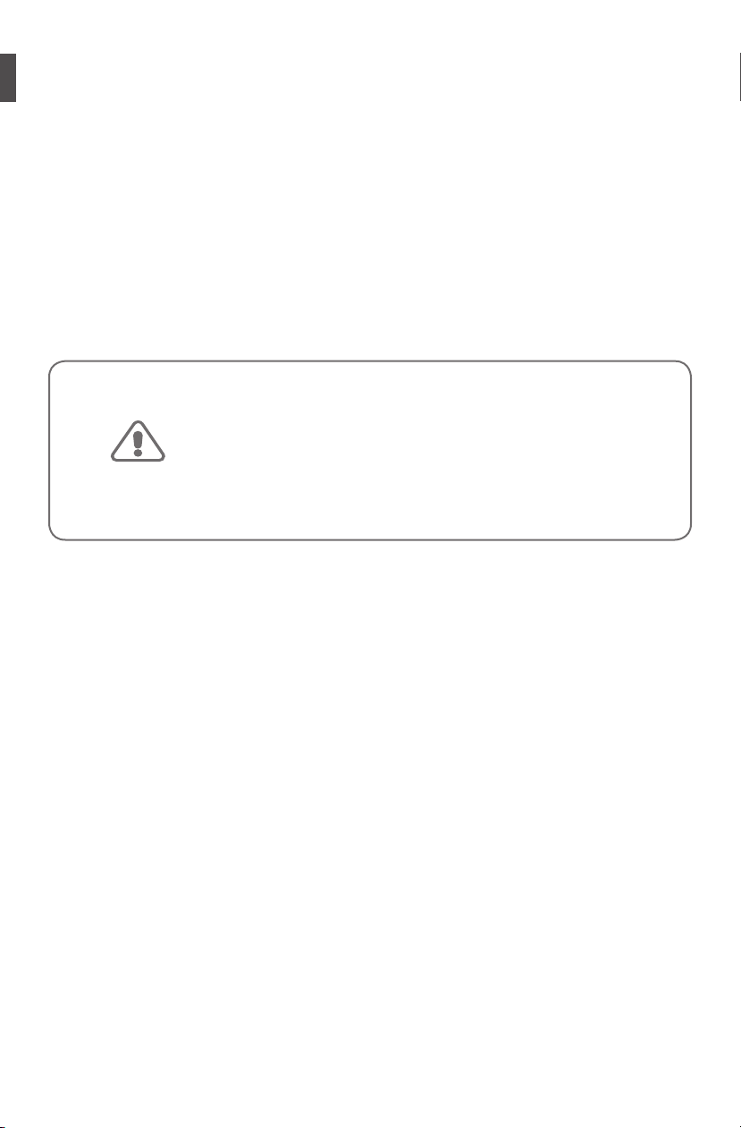
4.2 Sub-floor preparation
1. Ouellet Canada Inc. strongly recommends the installation of rigid thermal insulation panels (styrofoamtype - 2” minimum) underneath the concrete slab, (tongue and groove or joints taped with adhesive),
with a RSI coefficient between 7.5 to 10 R to help reduce the loss of heat at the bottom level. Please refer
to the building code for recommendations pertaining to concrete sub-floors.
Note: Please refer to the building code for recommendations pertaining to concrete sub-floors.
Image 1
13
Page 14

4.3 Floor markings
WARNING!
1. Use empty spaces (during construction or renovation) and with a marker or spray, draw markings on
the selected rigid insulation, indicating fixed elements to be bypassed (drains, walls, obstacles, etc.).
These markings will help delineate the area to be covered while keeping OWC-M heating cables at a safe
distance from those fixed elements.
2. Allow for a buffer zone at the end of each area for excess cable, if need be.
3. Identify the starting point for the concrete heating cable and the space required for the installation of
the cold lead duct.
4. Identify the location of the temperature sensor and temperature control device.
Image 2
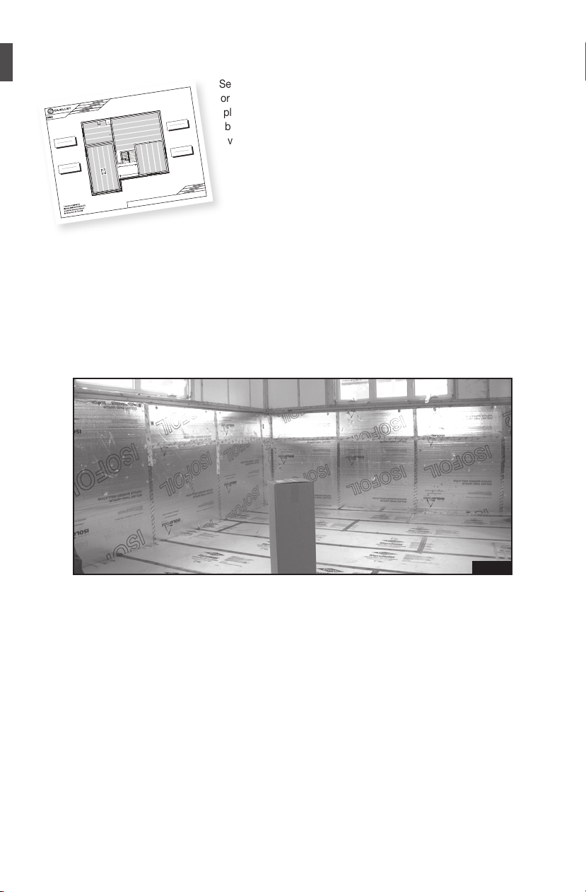
4.4 Power levels and measurement chart
The master electrician in charge of installing and connecting the OWC-M concrete heating cable system must
fill the measurement chart at each stage of the installation process. The measurement chart is located on
the electrical panel label which is supplied in the box with the product. This chart must be supplied to the client
and placed near the electrical panel.
Image 3
If the chart is not filled in properly, the warranty will
be cancelled. Warranty conditions are specified in section 7.
14
Page 15
4.5 Installation of concrete heating cables – OWC-M series
1. Before removing the product from the box, take
the resistance and cable insulation details compare
them to the factory results on line #1 of the measurement
chart on the electrical panel label.
Note: The security seal from Ouellet Canada Inc.
guarantees the integrity of the cable in the box. Once
the seal is broken, the customer becomes responsible
for the integrity of the cable during the installation process.
Please follow instructions carefully and adhere to
recommended safety measures.
2. Remove the material from the box (cable, fasteners,
fault indicator, temperature sensor).
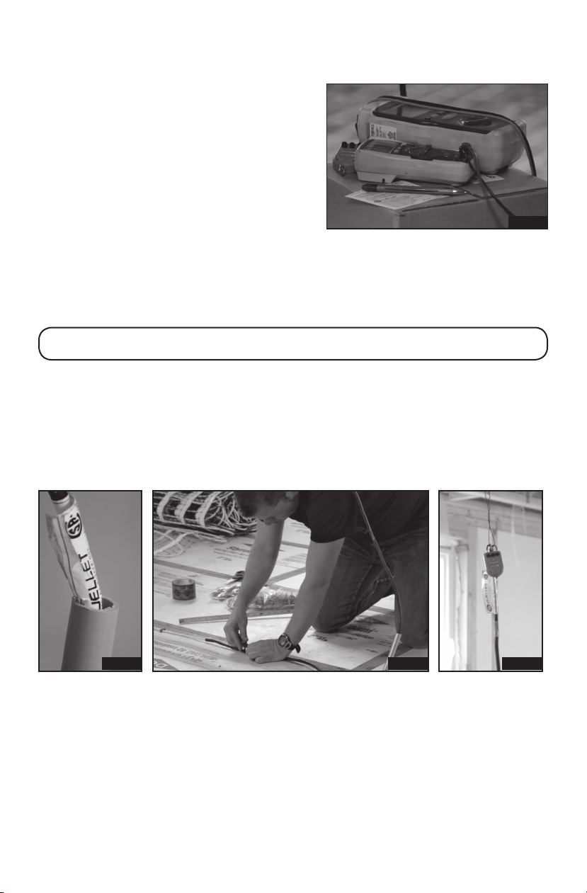
3. Install the cable duct for the cold lead at the pre-determined location, (where the cable mat will be unrolled).
4. Feed the cold lead into the cable duct making sure the mechanical connection between the cold lead and
the heating cable remains outside the cable duct by at least 12” (30 cm). There should be no part of
the heating cable found near the cable duct.
ATTENTION! There should be no part of the heating cable found near the cable duct or inside the wall.
5. Install the electrical fault indicator in compliance with instructions, at the end of the cold lead.
6. Hang the cold lead and electrical fault indicator, using string or a hook, from one of the ceiling joists
or other element so it is close at hand but making sure it doesn’t obstruct the installation process.
Note: Make sure the cold lead is long enough to reach the thermostat or junction box.
7. Switch the electric fault indicator on.
Note: If the electrical fault indicator ON during the installation, immediately postpone the heating cable instal-
lation and contact Ouellet Canada’s technical specialists.
Image 4
Image 5 Image 6 Image 7
15
Page 16

8. Unroll the OWC-M sections while adhering to the required clearances and anchor cables onto the thermal
WARNING!
insulation using the fasteners supplied with the kit. It is very important to solidly anchor the cables onto
the thermal insulation using the fasteners to ensure the installation is securely in place during the concrete
pouring process.
Note: We recommend loosely anchoring the fasteners while first unrolling the sections (in the event of errors
or modification of boundaries) and to anchor the cables more firmly thereafter when the process is complete
(see step 4.5.3).
Image 8 Image 9
9. For bypassing walls and obstacles, please refer to the instructions in paragraph 4.5.1.
4.5.1 Bypassing walls and obstacles
• Never attempt to cut or shorten a heating cable.
• Be very careful while maneuvering onto the heating cables.
• It is important not to subject heating cables to any kind of mechanical
stress (stretching, bend radius less than 1.5” (38 mm), notches).
A. Upon encountering walls, simply cut the mat and rotate it in another direction. Use scissors to cut
the mats, being very careful not to damage the cables and use the floor fasteners to secure both
extremities of the mats onto the thermal insulation.
Image 10 Image 11 Image 12
16
Page 17

B. Upon encountering any obstacle or fixed element to be bypassed, simply cut the mats and remove
the cable over a certain length so as to easily be able to bypass the obstacle. Use scissors to cut
the mats being very careful not to damage the cables and use the floor fasteners to secure the cable
in place around elements to be bypassed.
Image 13 Image 14
Note: It is possible to use adhesive tape (‘tuck’ tape) to secure the mats or OWC-M cables onto
the thermal insulation. However, we recommend using the fasteners supplied with the kit to ensure
a sturdy installation.
Image 15
17
Page 18

4.5.2 Installation of temperature sensor
WARNING!
1. Once the mats are unrolled, install the cable duct for the temperature sensor at the pre-determined
location.
Note: The ideal location for the temperature sensor is a site exempt from any obstacles (walls,
doors, etc.).
2. Feed the temperature sensor into the appropriate cable duct and locate it between two parallel OWC-M
heating cable mats.
3. The temperature sensor must be installed as near as possible to the floor surface and solidly anchored
with a piece of wood or polystyrene foam so it will not shift during the concrete pouring process.
Note: Make sure the sensor is long enough to be connected to the thermostat.
Image 16 Image 17
The temperature sensor must be
completely encased in concrete.
18
4.5.3 Final steps while securing the installation
1. Once the installation of the cables and sensor is complete, you must then secure the entire installation
by adding plastic floor fasteners on the cables and the sensor. A sufficient quantity of fasteners is
supplied with the kit to ensure the installation of one (1) fastener at every feet (12 cm) of mats.
Note: We recommend securing the beginning and end of every mat section with 4 fasteners and then
allocating the rest of the fasteners at every 2 feet maximum over the entire installation.
2. Once all fasteners have been installed, have ready the material required for the protection of the
concrete cables in accordance with the concrete pouring method selected. See section 4.6.
3. Lastly, check the resistance and cable insulation and record these measures on line # 2 of the measurement chart on the electrical panel label.
Page 19

4.6 Concreting
WARNING!
1. Before the concrete is poured, measure the resistance
and cable insulation and record these values on line #3
of the measurement chart on the electrical panel label.
2. Switch the electrical fault indicator on BEFORE any
circulation on the concrete cables and BEFORE
the concreting process begins.
If the electrical fault indicator rings during the pouring
process, mark the location where the cable was damaged
using a stake. Delineate an area at least 2 ft
around the location where the cable was damaged and
DO NOT COVER that area with concrete. Finish the
concreting process and call Ouellet Canada Inc.’s
specialists for a repair kit (OWC-KIT) used for repairing
the concrete cable.
Image 19
2
(0.18 m2)
Image 18
3. Install the material required for the protection of the heating cables during the concrete pouring process:
A. When using a concrete pump:
- Pay special attention when moving around the mats so as not to damage the cables.
- Always place pieces of plywood or polystyrene foam underneath the pump hose, more specifically,
under the joints and connections to ensure they do not come into contact with the heating cables.
- Once the pump is activated and the concrete is pouring, always lift the end of the hose to ensure
it does not come into contact with the heating cables.
19
Page 20

B. Concreting process using a wheelbarrow:
- Pay special attention when moving around the mats so as not to damage the cables.
- Protect the heating cable installation with a piece of plywood while moving the wheelbarrow around.
- It is important to install a plywood panel underneath the wheelbarrow before pouring any concrete
so the wheelbarrow buffer does not come into contact or damage the heating cables.
- Avoid using the same trajectory with the wheelbarrow. This will allocate stresses throughout
the entire installation.
Image 20
4. The heating cable system must be encased with a minimum of 4” to 6” (10 to 15 cm) of concrete.
Note: It is imperative that the ENTIRE heating cable installation be encased in concrete. There should be no
jutting parts or heating cable visible.
5. If using a metallic structure for reinforced concrete, pay special attention to the cables while moving around
the reinforcement structure. Make sure enough wedges or bricks have been used to ensure the structure can
withstand any shifting as well as the weight of the concrete, without varying in height. Be careful not to catch
any of the cables with the tools.
6. Level the concrete in a normal fashion paying special attention not to catch any of the cable ducts used for
the cold lead or temperature sensor.
20
Image 21 Image 22
Page 21

4.7 Electrical connection
WARNING!
WARNING!
Electrical connection must be performed by a master electrician,
only after the cable has been installed and encased in concrete
and the curing of concrete period is complete.
WARNING! DANGER OF ELECTROCUTION: always make sure
the power supply circuit is turned off before proceeding with
the electrical connection.
1. Measure the resistance and cable insulation and record these values on line # 4 of the measurement chart
on the electrical panel label.
2. Use a control device from Ouellet to perform the connection of the OWC-M concrete cable system. Refer
to section 5 to help assist you in the selection of a suitable control device for your installation.
3. Perform the connection in compliance with instructions provided in Ouellet’s operating guides for controls
and in compliance with local and national electrical specifications in effect.
240/208V and 347V connection:
Line 1 - black
Line 2 - red
Ground – yellow/green
4. For installations requiring more than one electric circuit, obtain an adequate control kit from Ouellet which
includes a master thermostat as well as a sufficient number of slaves depending on the system’s power.
5. Lastly, identify the circuits at the electrical panel and stick the completed label to the electrical panel which
includes all the measurements taken during the installation process.
Do not power up the OWC-M concrete cable system
before the concrete curing process is complete in accordance
with the manufacturer’s recommendations
(check with the concrete supplier).
4.8 Putting into service
When the OWC-M concrete cable system is ready to be put into service, activate the circuit breaker and set
the temperature according to your desired level of comfort.
Image 25
21
Page 22

5. Control device
The OWC-M heating cable system must be controlled with an adequate temperature regulator depending on
the type of system selected: floor control mode or ambient control with floor limit mode.
5.1 Installation for floor control mode
We recommend using an electronic floor temperature control device with a temperature sensor so the thermal
gain never exceeds the maximum temperature allowed for the type of floor covering selected. Control device
recommended: Electromechanical thermostat with floor mode (F) and temperature sensor.
5.2 Installation for ambient control with floor limit mode
The thermal control device is an ambient thermostat. Because the thermostat reacts to ambient temperatures
and not floor temperature, the floor covering must be selected according to a higher tolerance level. The
ambient thermostat or temperature sensor should never be installed where sun rays are prevalent or in an area
subject to drafts. Control device recommended: Electromechanical thermostat with ambient mode (AF)
and temperature sensor.
Note : Ouellet Canada Inc. highly recommends connecting the concrete cable system to a ground fault circuitbreaker/detector (GFCI), built-into the control device or directly integrated into the circuit-breaker.
5.3 List of control devices
The following is a list of control devices (sold separately) recommended for OWC-M concrete heating cable
systems:
240/208V OWC-M0300 to OWC-M3400
Total current: 15 A and less (no relay):
Non-programmable electromechanical thermostat – series OTH770 with temperature sensor
and GFCI 15 A @ 120/208/240V.
Programmable electromechanical thermostat – series TH115-AF with temperature sensor
and GFCI 15 A @ 120/208/240V.
Total current: 15A to 22A (with 1 relay):
Non-programmable electronic master thermostat, low voltage, 12 VDC – OTH700-AF-12VDC
with temperature sensor AND
Slave module – series CT230, with GFCI - 15A @ 120/208/240V OR
Programmable electronic master thermostat, low voltage, 12 VDC, TH115-AF-12VDC
with temperature sensor AND
Slave module - series CT230 with GFCI - 15A @ 120/208/240V OR
Non-programmable electronic thermostat – low voltage, series OTH824 with temperature sensor
and without GFCI AND
On/Off relays with transformer RC840T-240 - 22A @ 208/240V OR
TRIAC relays with transformer RT850T-240 - 23A @ 208/240V
Total current 22A and more (with 2 or more relays):
Non-programmable electronic thermostat – low voltage, series OTH824 with floor relay and without GFCI AND
On/Off relays without transformer RC840 - 22A @ 120/208/240V OR
TRIAC relays without transformer RT850 - 23A @ 120/208/240V/347
22
Page 23

240/208V OWC-M3700 and OWC-M4000
Total current from 15A to 22A (with 1 relay):
Non-programmable electronic thermostat – low voltage, series OTH824 with temperature sensor
and without GFCI AND
On/Off relays with transformer RC840T-240 - 22A @ 208/240V OR
TRIAC relays with transformer RT850T-240 - 23A @ 208/240V
Programmable electronic thermostat – low voltage, series TH115-AF-024T/U with temperature sensor
and without GFCI AND
On/Off relays with transformer RC840T-240 - 22A @ 208/240V OR
Programmable electronic thermostat – low voltage, series TH115-AF-024T-15S with temperature sensor
and without GFCI AND
TRIAC relays with transformer RT850T-240 - 23A @ 208/240V
Total current - 22A and more (with 2 or more relays):
Non-programmable electronic thermostat – low voltage, series OTH824 with temperature sensor
and without GFCI AND
On/Off relays without transformer RC840 - 22A @ 120/208/240V OR
TRIAC relays without transformer RT850 - 23A @ 120/208/240V/347
347V OWC-M2007 to OWC-M4007
Total current - 15A à 22A (with relay):
Non-programmable electronic thermostat – low voltage, series OTH824 with temperature sensor
and without GFCI AND
On/Off relays with transformer RC840T-347 - 18A @ 347V OR
TRIAC relays with transformer RT850T-347 - 23A @ 347V
Programmable electronic thermostat – low voltage, series TH115-AF-024T/U with temperature sensor
and without GFCI AND
On/Off relays with transformer RC840T-240 - 22A @ 208/240V
Programmable electronic thermostat – low voltage, series TH115-AF-024T-15S
with temperature sensor and without GFCI AND
TRIAC relays with transformer RT850T-240 - 23A @ 208/240V
Total current - 22A and more (with 2 or more relays):
Non-programmable electronic thermostat – low voltage, series OTH824
with temperature sensor and without GFCI AND
TRIAC relays without transformer RT850 - 23A @ 120/208/240V/347
OTH770
Non Programmable
Electromechanical Thermostat
CT230
Slave Unit
OTH824
Low Voltage
Electronic Thermostat
RC840
On/Off Relays
TH115
Programmable
Electromechanical Thermostat
RT850
Triac Relays
23
Page 24

6. Frequently asked questions (FAQ)
Q.1: Can we cut the OWC-M heating cable to reduce its length?
A.1: NEVER. When the OWC-M concrete cable mat is too long, spread the excess over the entire floor. To
achieve this, arrange the heating cable mat in regular loops while adhering to minimum distances, along wall
partitions and between parallel sections of the heating cable mat.
Q.2: What should be done before choosing the adequate OWC-M product?
A.2: Draw out a plan of the area to be covered. Follow steps 1 to 7 in paragraph 4.1 of the present manual or
send a copy of your construction plan by fax to 1 800 662-7801 or via e-mail to info@ouellet.com. Make sure
you send a copy of the plan to scale as well as a list of all fixed elements which have to be bypassed. At the
very least, we will need a horizontal measure and a vertical measure to validate the scale. Our technical support
technicians will be pleased to provide you with a list of material and a layout sketch to guide you through your
installation.
Q.3: How do we repair the OWC-M cable in case of breakage?
A.3: First, (as a preventive method) from the very start, you should test the cable each time it is indicated in the
instruction book. As well, you should fill out the measurement chart (label supplied in the kit). However, in case
of breakage, if the concrete pouring process has not begun, contact Ouellet Canada Inc.’s technical support
services and ask for a repair kit (OWC-KIT). If the pouring process has begun, delineate an area at least 2 ft2
(0.18 m2) around the damaged cable and DO NOT cover that area with concrete. Once the concreting process
is complete, contact Ouellet Canada Inc.’s technical support services and ask for a repair kit (OWC-KIT).
Technical support services can be reached at: 1 800 463-7043
Q.4: Are there different power levels available by square foot?
A.4: Ouellet Canada Inc. estimates that 11W/ft2 (120W/m2) with a spacing of 6’’ (15 cm) is an adequate value
which should not be exceeded in order to optimize your comfort level without creating any overheating hazard.
Furthermore, the power level per ft2 (m2) is identical for 240/208V and 347V cables.
Q.5: Can two heating cables cross, overlap or touch one another?
A.5: NEVER. This could create an overheating hazard. A minimum of 6” (15 cm) space must be maintained
between cable mats.
24
Page 25

Q.6: Can the cable be bent at a 90° angle?
A.6: Yes, however you must retain a minimal bend radius of 1.5’’ (38 mm). A radius inferior to 1.5” (38 mm) could
cause mechanical breakage.
Q.7: Can two OWC-M heating cable systems be installed on top of one another?
A.7: NEVER. This could create overheating hazards and damage the cables.
Q.8: Can OWC-M concrete heating cables be used outside for snow removal purposes?
A.8: No. OWC-M heating cables are designed as a comfort or heating product for residential interior applica-
tions only.
Q.9: Is it mandatory to have a ground fault circuit-breaker-detector?
R.9: Although Canadian regulations in effect do not require the installation of a ground fault circuit-breaker/
detector, we highly recommend its use for concrete cable applications. In the United States, the use of a ground
fault circuit-breaker/detector is mandated by regulations for all concrete cable installations.
Q.10: Must we have a temperature sensor?
A.10: Yes. This will control the floor surface temperature so it does not exceed the maximum temperature
allowable for the type of floor covering used. Although it is not mandatory to have a temperature sensor when
the system is used with an ambient air thermostat, Ouellet Canada Inc. recommends using a temperature
sensor as well.
Q.11: Can two OWC-M concrete cable systems be connected to the same thermostat?
A.11: Yes, (more if need be) parallel-connected if the total capacity does not exceed that of the thermostat.
Q.12: What happens when the voltage applied is the wrong one?
A.12: A product intended for 240/208V connected to 347V: there will be overheating and then a breakdown will
occur. A product intended for 347V but connected to 240V/208V: will hardly heat. It is therefore very important
to connect the product to the proper voltage.
25
Page 26

7. Warranty
Subject to provisions stipulated in the Consumer Protection Act’s legal requirements respecting the quality and
durability of goods: Ouellet Canada Inc. guarantees its OWC-M heating cables and its heated floor systems for
a period of 20 years from the date of purchase against any manufacturing defect or malfunction.
Limitations and exclusions
The above mentioned guarantees are limited to the reimbursement of the original purchase cost or replacement
of the heating cables and/or defective thermostat (hereinafter called equipment) excluding any other part and
also excluding any cost or any expense relating to connection, removal or installation of aforesaid equipment,
including all workmanship costs. The buyer may choose between the reimbursement of the original purchase
cost and the replacement of defective equipment, subject to the aforementioned restrictions. This warranty is
provided to the original buyer of the equipment as well as subsequent owners of the building where the equipment was installed.
Warranty terms
The above mentioned warranties are subject to the following conditions:
i. The buyer must provide the original purchase invoice for the defective equipment, to Ouellet Canada Inc. or to
one of their authorized dealer;
ii. The buyer must report promptly in writing to Ouellet Canada Inc. any malfunction of equipment covered by
the present warranties, in a reasonable time frame, from the time the malfunction occurred or the malfunction
was brought to their knowledge thereby enabling Ouellet Canada Inc.’s representatives enough time to verify
the defective equipment, if need be;
iii. Equipment covered under the present warranties must be installed in compliance with Ouellet Canada Inc.’s
instructions;
iv. Equipment covered under the present warranties must be used under normal conditions of use and
be maintained on a regular basis from the date of purchase.
Name and address of the person providing the present warranties:
Ouellet Canada inc.
180, 3e Avenue
L’Islet (Québec) G0R 2C0 CANADA
Telephone: 1 800 463-7043 or 418 247-3947
Fax: 1 800 662-7801 or 418 247-7801
info@ouellet.com
www.ouellet.com
Notes
26
Rev. 1, March 2012
 Loading...