

Page 1
e700
e700
e700e700
Automatic Transport
Automatic Transport VVVVentilator
Automatic TransportAutomatic Transport
User Manual
User Manual
User ManualUser Manual
e700 User Manual
entilator
entilatorentilator
(15PL1009 - Rev.10 Dec 21, 2016) English version
0000
Page 2

3.1 Control and Display Layout
…………………………………..
………..
7
3.2 Function Keys
……………………………………………………..
………..
…… 8
3.2.1 ON/OFF
……………………………………………………..
………..
…… 8
3.2.2 Co
nt
rol S
el
ection K
nob……………………………
………..
…… 8
3.2.3 Lo
ck…………………………………………………………….
………..
…… 9
3.2.6 Day/night
…………………………………………………
………..
…… 9
3.3 External Connectors
………………………………………………
………..
12
3.4 Patient circuit
………………………………………………
………..
12
4.1.1 Connecting electrical power supply …………………….
18
4.1.5 Turning Ventilator ON
……………………………………
20
4.2 Pre
-
use check ………………………………………………………………………
21
5.2
Table of Contents
Table of Contents
Table of ContentsTable of Contents
Chapter 1 Safety……………………………………………………………………………………………
…………………………………………………………………………………………….... 3
…………………………………………………………………………………………………………………………………………………………………………………………
Chapter 2 Intended Use…………………………………………
Chapter 3
Chapter 4
Overview ………
3.2.4 Alarm Silence……………………………………………..………..…… 9
3.2.5 Waveform …………………………………………………………..…… 9
3.2.7 Cancel ………………………………………………………..………..…… 10
3.2.8 Pause/Resume………………………………………..………..……… 10
3.2.9 Manual / Inspiratory Hold ……………………..………..…… 11
3.5 Display ……………………………………………………………………………….. 13
3.5.1 Screen Layout ……………………………………………..………..…… 13
3.5.2 Live Monitoring Parameters ………………………………..…… 15
3.6 Symbols & Notations ……………………………………………………….. 17
Preparation For Use ……………………………………
4.1 Set up ……………………………………………………………………………………… 18
…………………………………………………………………………………
……………………………………………………………………………………
…………………………………………………………………………………….
……………………………………………………………………………. 7
………………
…………………………………………………………………………….…………………………………………………………………………….
………………………………………………………………….
…………………………………………………………………………
……………………………………… 6
………………………………………………………………………………
……………………………. 18
…………………………….…………………………….
Chapter 5
4.1.2 Installing / replacing the battery ………………………… 18
4.1.3 Connecting the gas supply ………………………………….. 19
4.1.4 Connecting patient circuit …………………………………… 20
Operating Instructions ………………………………………………………………
5.1 Startup & setting the ventilation parameters ……………….. 23
Ventilation modes…………………………………………………………………. 27
5.2.1
A/C V (Assist Control Ventilation) ……………………………….
5.2.2
Ventilation) ……………………………………………………………………….
5.2.3
5.2.4. CPAP (Continuous Positive Airway Pressure)…………..
5.2.5 CPR mode ………………………………………………………………. 36
5.3 Turning Ventilator OFF …………………………………………………….. 39
SIMV (Synchronized Intermittent Mandatory
BiLVL (Biphasic Positive Airway Pressure). ………………
e700 User Manual
……………………………………………………………… 23
………………………………………………………………………………………………………………………………
28
30
32
34
1111
(15PL1009 - Rev.10 Dec 21, 2016) English version
Page 3

Chapter 6 Post use ……………………………………………………………………………………
…………………………………………………………………………………… 40
…………………………………………………………………………………………………………………………………………………………………………
6.1 Disconnect device after use …………………………………………….. 40
6.2 Storage ………………………………………………………….…………………….. 40
Chapter 7 Alarms and Indicators ………………………………………………………………
……………………………………………………………… 41
………………………………………………………………………………………………………………………………
7.1 Ventilation Alarms …………………………………………………………….. 41
7.2 Battery status indicator ……………………………………………………. 43
7.3 LEDs …………………………………………………………………………………….. 44
Chapter 8 Cleaning, Preventive Maintenance & Servicing ………………………
……………………… 45
………………………………………………
8.1 Cleaning & Disinfection ……………………………………………………. 45
8.2 Charging the Battery ……………………………………………………. 45
8.3 Ambient Air entrainment Filter ………………………………………….. 46
8.4 Preventive Maintenance and Servicing ……………………………… 46
Chapter 9 Technical Data …………………………………………………………………………..
9.1 Specifications ……………………………………………………………………..
9.2 Circuit Description …………………………………………………………….
………………………………………………………………………….. 48
…………………………………………………………………………..…………………………………………………………………………..
…………………………………………………………………….. 48
……………………………………………………………………..……………………………………………………………………..
……………………………………………………………. 50
…………………………………………………………….…………………………………………………………….
9.3 Battery and Power Supply ……………………………………………….. 51
9.4 Battery Operating time …………………………………………………….. 52
9.5 Electromagnetic Compatibility ………………………………………. 53
9.6 Oxygen consumption ……………………………………………………….. 55
Chapter 10
Chapter 11
Chapter 12
Chapter 13
9.7 Oxygen Concentration delivered against different back
pressures …………………………………………………………………..………..
Trouble Shooting ……………………………………………………………
Abbreviations and Acronyms……………………………………………………
Accessories ……………………………………………………………….
Warranty ……………………………………………………………………………………..
……………………………………………………………….………………
……………………………………………………………….……………………………………………………………….
…………………………………………………………………………………….. 60
……………………………………………………………………………………..……………………………………………………………………………………..
……………………………………………………………………….
…………………………………………………………………………………………………………………………
…………………………………………………… 58
…………………………………………………………………………………………………………
…………. 57
………….………….
……………… 59
………………………………
56
e700 User Manual
(15PL1009 - Rev.10 Dec 21, 2016) English version
2222
Page 4

Chapter 1 Safety
WWWWarning
arningssss
arningarning
Safety
SafetySafety
Federal Law restricts this device to sale by or on the order of a physician.
The ventilator shall only be used for purposes specified under “Intended
Use”.
The ventilator should only be used by qualified personnel trained in its
use.
Strict adherence to all instructions contained within this manual is
essential for safe use.
During use, the patient must be constantly monitored by qualified
personnel.
Alternate means of ventilation must be available in case of power failure
or malfunction.
Keep away from open flames, sparks and grease/oil. To avoid the risk of
fire or explosion this ventilator must not be used with flammable gases
or anaesthetic agents. Operating the unit in a confined space will elevate
oxygen levels.
The ventilation setting will be interrupted during battery replacement
while the device is in operational mode and the external power supply is
not connected.
Only use O-Two specified hoses, patient circuits and external power
supplies to avoid affecting the output performance of the ventilator.
Antistatic or conductive hoses or tubing are not used in the Ventilator
Breathing System.
Unauthorized modification of this medical device is prohibited. Do not
disassemble or modify any part of the ventilator except where described
in this manual. Any unauthorized disassembly will void the warranty.
Do not use this ventilator in toxic environments as entrainment of ambient
room air during spontaneous breathing or air mix mode may permit toxic
gases to be delivered to the patient.
Do not use this ventilator within a Magnetic Resonance Imaging (MRI,
NMR, NMI) suite.
Do not use this ventilator in hyperbaric (high pressure) chambers.
e700 User Manual
(15PL1009 - Rev.10 Dec 21, 2016) English version
3333
Page 5

Do not use the external electrical power supply outdoors as moisture may
affect its function.
Do not contact the connector from the power supply and the patient
simultaneously.
The performance of this ventilator may be affected if used around
portable and mobile RF telecommunication devices (cell phones) within
the minimum distance specified in section 9.5 of this user manual.
Intake port on the patient valve must be left unobstructed for proper
function & safety.
When using a bacterial filter or HME (Heat Moisture Exchanger) connect
the bacterial filter or HME to the patient connection between the elbow
and the endotracheal tube or face mask, note that this action will increase
the dead space. Bacterial filters or HME may increase breathing
resistances.
Use pressure regulators maintaining a minimum output flow of 120 L/min
at a dynamic pressure of 45 PSI to ensure the proper functioning of the
ventilator.
Operation of this ventilator outside the environmental condition range
specified in this manual may result in reduction and or failure in the
ventilator’s performance. In extreme temperature conditions the effect is
not noticeable in terms of delivered ventilations but may cause excessive
wear in ventilator or components over time. Extreme low temperature
reduces operation time of the battery (Refer to 9.4 battery operating
Time).
Operation of this ventilator outside the supply pressures range detailed in
this manual may result in reduction in the ventilator’s performance,
component failure, low pressure alarm or possible loss of automatic
cycling.
Operation of this ventilator outside the electrical power range detailed in
this manual may result in reduction or failure in the ventilator’s
performance. Component failure, inadequate power of internal
components may occur.
Operation of this ventilator below sea level or above 4,000 m (13,000
feet) may result in reduction or failure in the ventilator’s performance, low
pressure alarm or possible loss of automatic cycling.
The ventilator is intended for use in the prehospital, intrahospital,
interhospital and ground transport environments only.
Connecting the patient circuit to a patient prior to turning on the
ventilator may cause a calibration error.
e700 User Manual
(15PL1009 - Rev.10 Dec 21, 2016) English version
4444
Page 6

CCCCaution
autionssss
autionaution
When the ventilator is not in use, always turn off the gas supply.
Never allow oil or grease to come into contact with any part of the
cylinder, regulator, or ventilator.
After use, always ensure that all components are cleaned in accordance
with the instructions provided in this manual. (See section 8.1 - Cleaning
and Disinfection).
The use of this device in a carrying case may result in an increase in
oxygen concentration or lower than intended ventilation volume when
used in the 60 % air mix mode. When air mix mode is being used it is
recommended that the ventilator be placed in its normal operating
orientation and the air intake on the side of the ventilator is not
obstructed.
Never operate the ventilator without an intake filter being fitted,
otherwise particles may contaminate the ventilator and affect its
function.
This ventilator must only be serviced by the manufacturer or its
authorized service centers.
Device, single use patient circuits and battery packs should be safely
discarded in accordance with local state and institutional laws and
procedures. .
Spare O-Two patient circuits are recommended at all times.
The design of this Ventilator does not incorporate a negative pressure
phase during either automatic or manual ventilation.
The external power supply and battery are component parts of the
medical electrical equipment system.
The ventilator is considered as a high flow device as its maximum flow
output at pressure of 40.6 PSI is around 75 L/min. It should only be
connected to a pipeline system that allows for the indicated high flow to
avoid interfering with the operation of adjacent equipment.
Always ensure that all components are assembled correctly and ready
for use.
Exhaled volume of the patient can differ from the measured exhaled
volume due to leaks around the mask.
When selecting very small tidal volumes during ventilation of infants
with, take into consideration the dead space in the patient circuit.
e700 User Manual
(15PL1009 - Rev.10 Dec 21, 2016) English version
5555
Page 7

Chapter 2 Intended Use
Intended Use
Intended UseIntended Use
The e700 is a time-cycled, volume-constant and pressure-controlled
emergency and transport ventilator designed for use in the pre-hospital, intrahospital, inter-hospital and transport settings. It is intended for use with Adult,
child, infant patients with a tidal volume from 50 ml upwards who are in
respiratory and/or cardiac arrest or respiratory distress and who require the
ventilatory support.
e700 User Manual
(15PL1009 - Rev.10 Dec 21, 2016) English version
6666
Page 8
Chapter 3 Overview
HHHH
JJJJ
EEEE
DDDD
CCCC
BBBB
NNNN
Overview
OverviewOverview
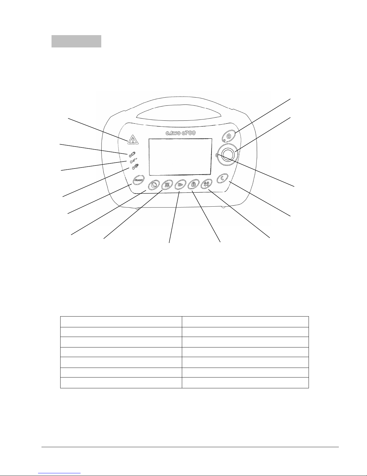
3.1 Control and Display Layout
AAAA
MMMM
LLLL
KKKK
FFFF
GGGG
Figure 1
Figure 1
Figure 1Figure 1
IIII
A - Warning indicator H – Pause/Resume button
B – Battery operation indicator I – Lock button
C – External power indicator J – Waveform selection button
D – Battery charging indicator K – Cancel button
E – Manual / Hold button L – Confirmation indicator light
F – Day / Night mode button M – Control Selection Knob
G – Alarm Silence button N – ON/OFF button
e700 User Manual
(15PL1009 - Rev.10 Dec 21, 2016) English version
7777
Page 9
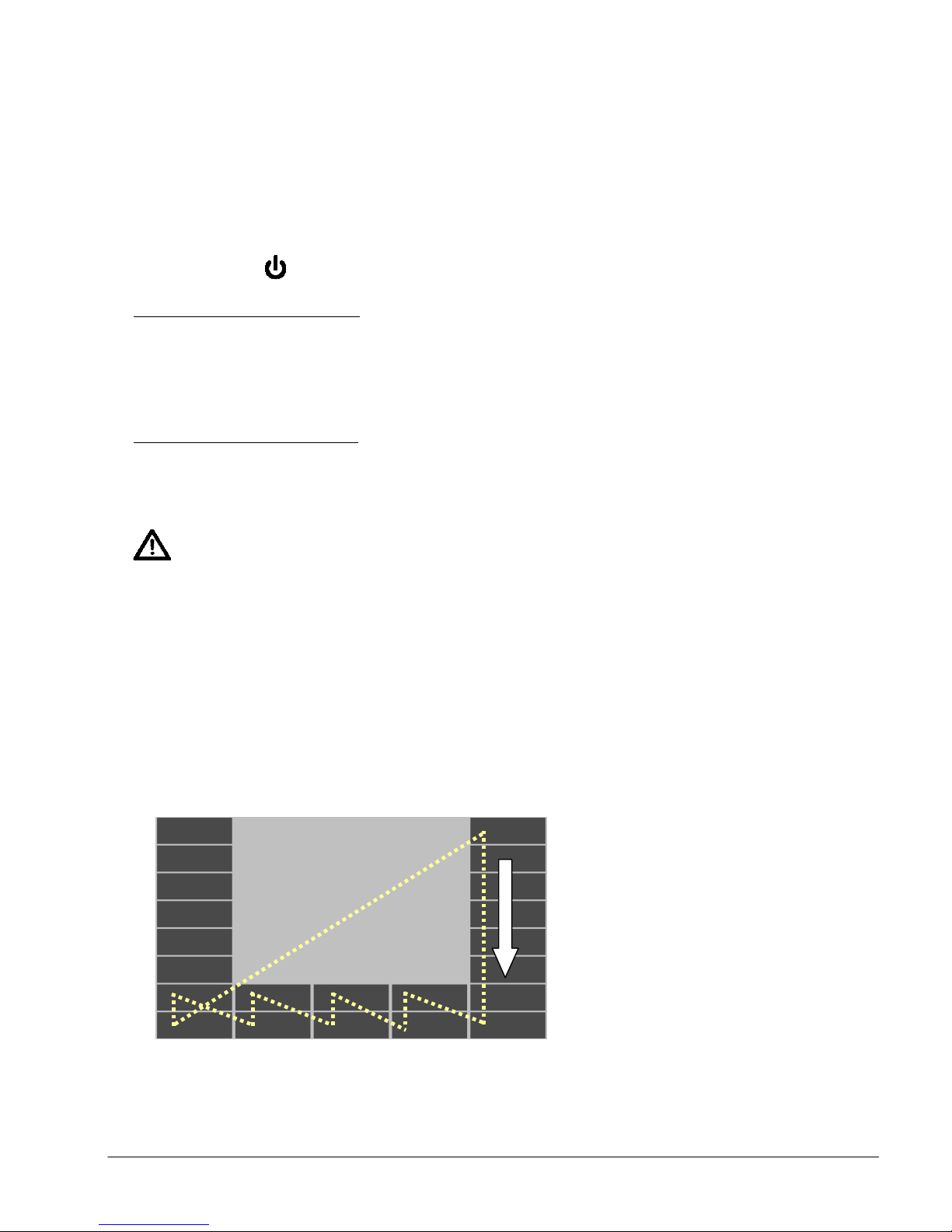
Direction for clockwise knob rotation
Direction for clockwise knob rotationDirection for clockwise knob rotation
Direction for clockwise knob rotation
3.2 Function Keys
While all ventilation parameter settings are controlled by the Control Selection
Knob (M) in Figure 1, there are a number of key membrane buttons which
control additional ventilator functions:
3.2.1 ON/OFF
To turn on the ventilator, Press the ON/OFF button (N) in Figure 1 for one
second, during that second the associated green LED will start flashing at a
high frequency. After 1 second the ventilator will turn on but without
ventilation until the appropriate patient size symbol is selected. If the button is
pressed and released for less than a second, the ventilator will remain OFF.
To turn off the ventilator, Press and hold the ON/OFF button for 4 seconds,
the green power LED will start flashing at a high frequency. After 4 seconds
the ventilator will turn off and all ventilation will stop. If the button is pressed
and held for less than 4 seconds, the ventilator will stay ON.
Warning
Warning
WarningWarning
At approximately 2% of full battery capacity, the ventilator will not start
when in the off position or will shut down when operating.
3.2.2 Control Selection Knob
The Control Selection Knob (M) in Figure 1 is used to navigate between
parameters, change modes, select primary function change when rotated,
and to confirm function changes when pressed. Diagram below illustrates
path of cursor when Control Selection Knob is rotated clockwise.
Control Selection Knob
Control Selection Knob
Control Selection Knob Control Selection Knob
rotation contour
rotation contour
rotation contourrotation contour
e700 User Manual
(15PL1009 - Rev.10 Dec 21, 2016) English version
8888
Page 10

Key Membrane Controls
3.2.3 Lock
Lock function will disable all buttons and the Control Selection Knob except
for the ON/OFF, Alarm Silence and Day/Night buttons, which are enabled at
all times.
To lock the key membrane or cancel the lock function:
1- Press Lock button (I) in Figure 1. The Lock symbol will be displayed on
the screen.
2- To cancel the Lock function, press the Lock button (I) again.
Note:
Note:
Note: Note:
During lock function, if any locked button is pressed, the Lock symbol will flash
while the locked button is pressed.
3.2.4 Alarm Silence
Alarm Silence button (G) in Figure 1 will silence audible alarms for 120
seconds. It can also be selected when there is no alarm in order to silence
potential alarms. This function is activated or deactivated by pressing the
Alarm Silence button once.
When selected, Alarm Silence symbol will be displayed on the screen.
3.2.5 Waveform
Pressing Waveform selection button (J) in figure 1 will switch between the
pressure and volume ventilation waveforms displayed on the screen.
3.2.6 Day/ Night
Day/ Night mode button (F) in Figure 1 will change brightness and contrast
of the text, waveform and background colors. The user can select either
one of the following by pressing the Day/ Night button once:
1- Day mode: Light background with dark text and waveform;
2- Night mode: Dark background with light color text and waveform. In this
mode all buttons and labelling information will also be illuminated.
e700 User Manual
(15PL1009 - Rev.10 Dec 21, 2016) English version
9999
Page 11

3.2.7 Cancel
The Cancel button (K) in Figure 1 allows the operator to return to the
previous settings if the last unconfirmed changes in settings are not
required.
3.2.8 Pause/ Resume
During activation of the Pause/ Resume button (H) in Figure 1, the
ventilator will stop ventilating with all buttons kept active (if they are not
locked) except Manual/ Hold button.
To activate pause function, proceed as follows:
1. Press Pause/ Resume button (H). The Pause symbol will flash on the
screen with the confirmation symbol
and the Confirmation indicator
(L) to guide users to activate pause function by pressing the Control
Selection Knob (M).
2. The symbol will be flashing for 10 seconds and then disappear if the
Control Selection Knob (M) is not selected. Users can also press the
Cancel button (K) to quit this selection before 10 seconds.
3. Once activated, a flashing yellow pause symbol will be displayed on the
screen and ventilator will stop ventilating.
Note
Note
NoteNote
a. During Pause, there will be an audible alarm associated with the
flashing yellow Warning indicator (A) in Figure 1 every 15 seconds.
Users can press Alarm Silence button to disable the audible alarm
for 2 minutes but the yellow Warning indicator will continue
flashing every 15 seconds.
b. During Pause, users can change and confirm new ventilation
settings but no ventilation will occur unless Pause function is
disabled.
4. To cancel Pause function, press Pause/ Resume button (H) again. The
“Resume” symbol will flash on the screen with the confirmation symbol
and the Confirmation indicator (L) to guide users to resume
ventilation by pressing the Control Selection Knob (M).
5. When ventilation is resumed, the ventilator will recommence ventilation
with current settings shown on the screen unless new set-up selections
were made.
e700 User Manual
(15PL1009 - Rev.10 Dec 21, 2016) English version
10
10
1010
Page 12

3.2.9 Manual/ Hold
During exhalation phase, if Manual/ Hold button (E) in Figure 1 is pressed, a
mandatory breath will be initiated and either the flow rate or set pressure
control parameter will be delivered as long as the Manual/ Hold button is
pressed or until I-time setting is achieved.
After I-time if the button still pressed, the ventilator will switch to
inspiratory hold function in which the ventilator will cut the flow but will
keep the exhalation port closed in order to block exhaled gas from going to
ambient resulting in the maintenance of lung pressure.
The maximum inspiratory hold time is 6 seconds. After that time, the
ventilator will switch to exhalation phase by opening airway pressure to
ambient.
Note:
Note:
Note:Note:
Manual/ Inspiratory Hold function exists in all modes except CPAP and
CPR.
e700 User Manual
(15PL1009 - Rev.10 Dec 21, 2016) English version
11
11
1111
Page 13
SSSS
QQQQ
PPPP
OOOO
X
Y Z
U
V
Fig
FigFig
Fig
ure 2
ure 2ure 2
ure 2
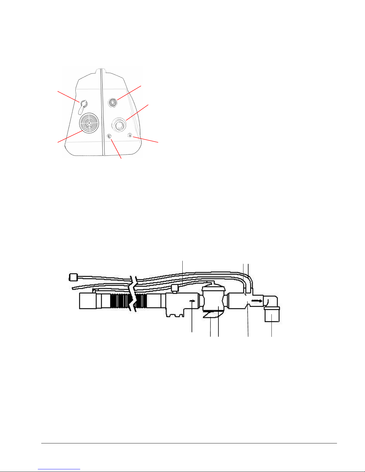
3.3 External Connectors
TTTT
RRRR
OOOO– DC Input connector
PPPP – Air Intake filter
QQQQ – Sensor connector #1
RRRR – Sensor connector #2
SSSS – 22mm gas output connector
TTTT – Gas supply input
3.4 Patient circuit
U: Breathing control hose
V: 2 pressure sensing hoses
W: one way intake valve
X: Exhalation port
Y: breathing valve
Z: Flow sensor adapter
W
e700 User Manual
λ
Fig
Figure 3
ure 3
FigFig
ure 3ure 3
(15PL1009 - Rev.10 Dec 21, 2016) English version
12
12
1212
Page 14
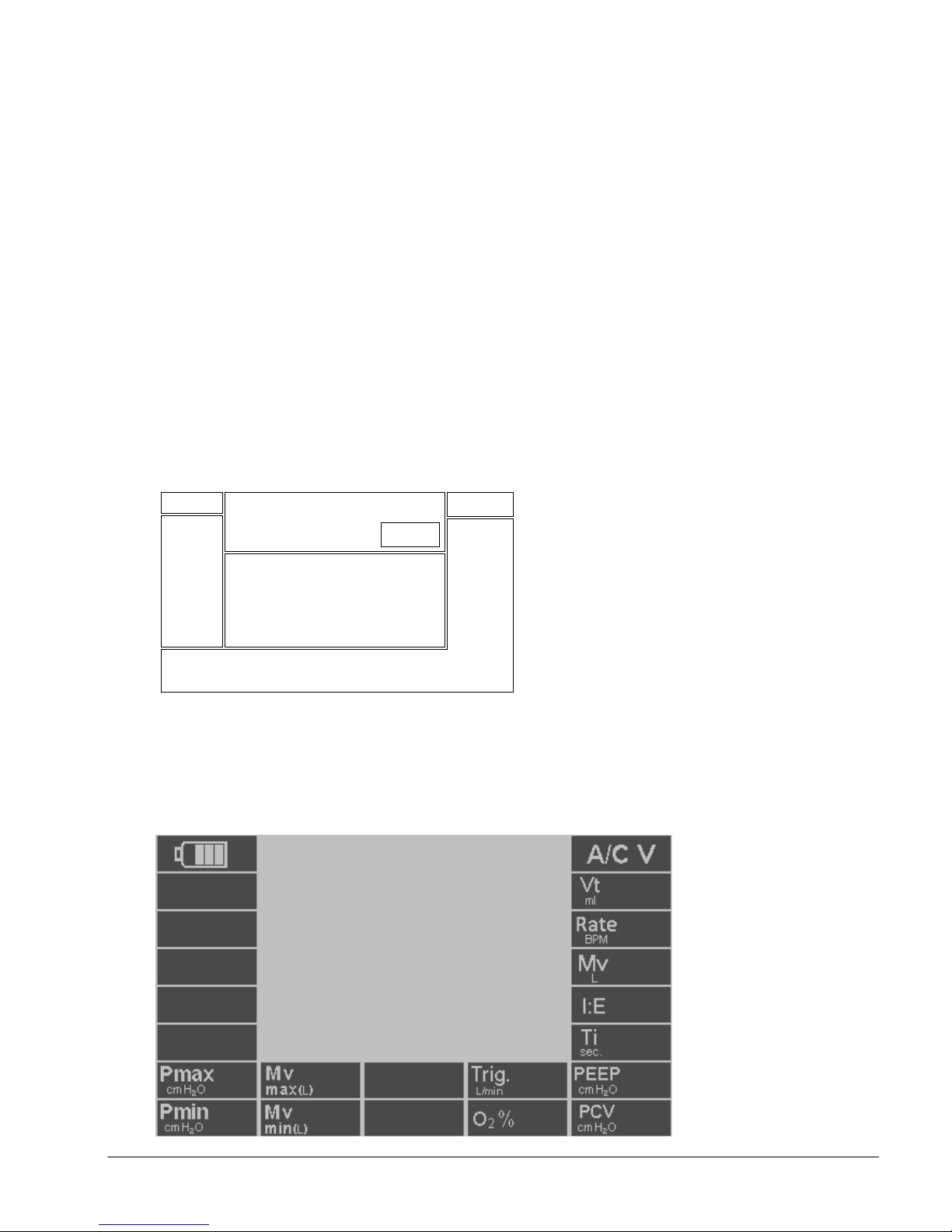
3.5 Display
4
2
7
A/C screen layout
A/C screen layoutA/C screen layout
A/C screen layout
3.5.1 Screen Layout
The screen is divided into 7 sections as shown below and each section is
dedicated to display the following parameters:
Section 1:
Section 1: Battery status during charge and discharge.
Section 1:Section 1:
Section 2:
Section 2: Live ventilation parameters (Vte, Mve, Paw
Section 2:Section 2:
Section 3:
Section 3: Ventilation Modes (A/C V, SIMV, BiLVL, CPAP & CPR).
Section 3:Section 3:
Section 4:
Section 4: Alarms/ Warnings.
Section 4:Section 4:
Section 5:
Section 5: Ventilation waveforms.
Section 5:Section 5:
Section 6:
Section 6: Set up parameters.
Section 6:Section 6:
Section 7:
Section 7: Confirmation request/ Patient effort/ Invalid or Conflict
Section 7:Section 7:
setting.
3 1
peak
, Paw
, Rate).
AV
5
Note:
Note:
Note:Note:
6
Fig
Figure 4
ure 4
FigFig
ure 4ure 4
By changing the ventilation mode, section 6 of the display will change
accordingly to reflect the default or set up parameters for each mode.
The followings are screen layouts for each ventilation mode:
e700 User Manual
(15PL1009 - Rev.10 Dec 21, 2016) English version
13
13
1313
Page 15
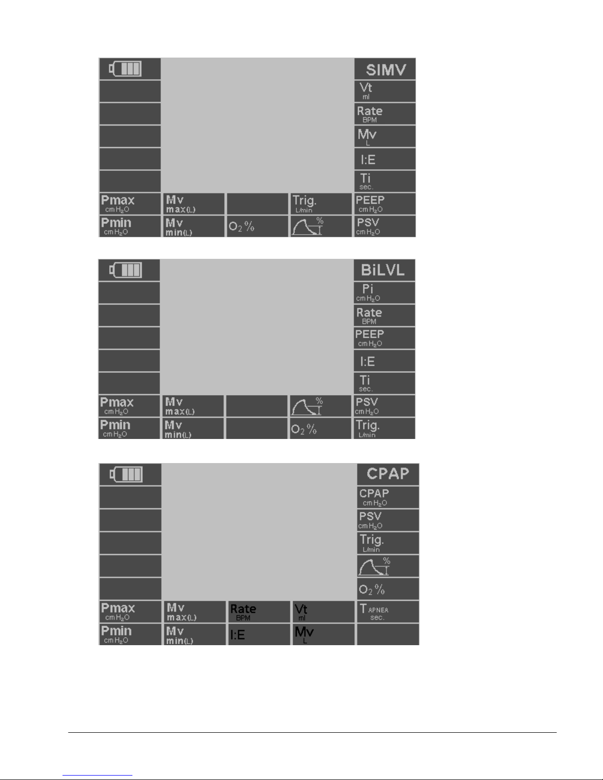
BiLVL screen layout
BiLVL screen layoutBiLVL screen layout
BiLVL screen layout
CPAP screen layout
CPAP screen layoutCPAP screen layout
CPAP screen layout
SIMV screen layout
SIMV screen layout
SIMV screen layoutSIMV screen layout
e700 User Manual
(15PL1009 - Rev.10 Dec 21, 2016) English version
14
14
1414
Page 16
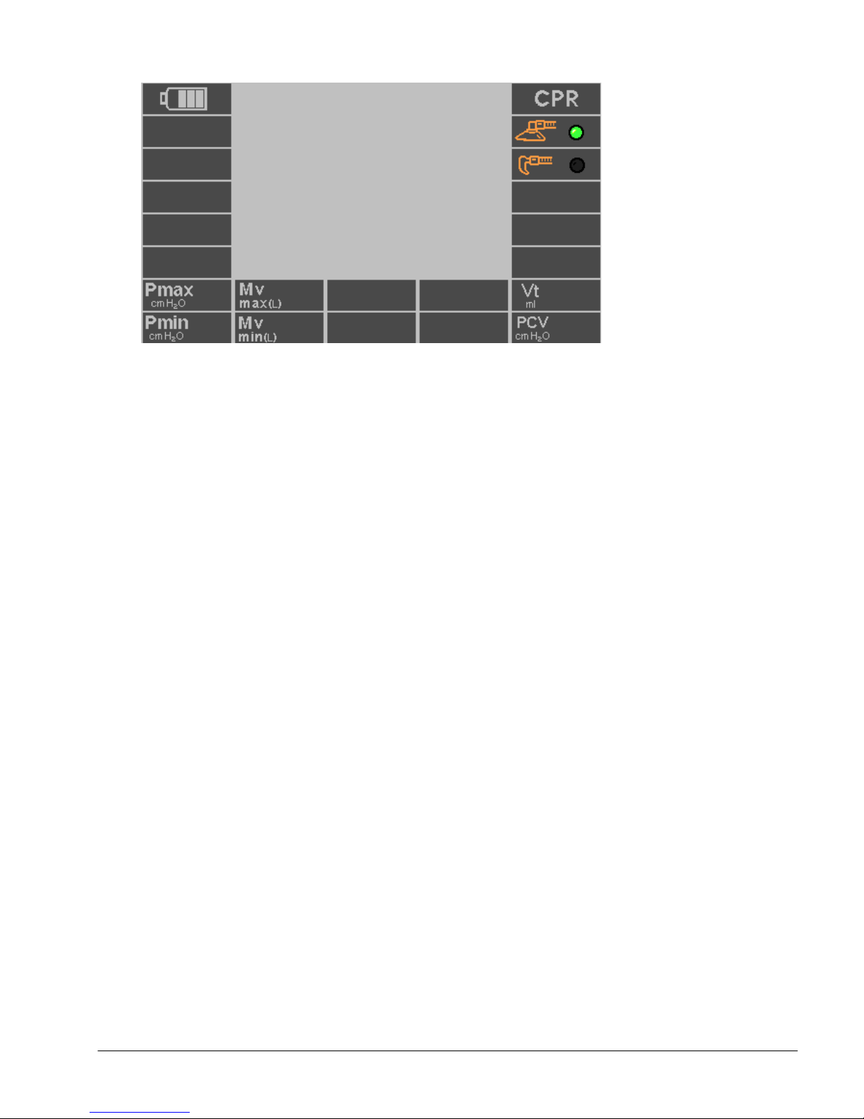
CPR screen layout
CPR screen layout
CPR screen layoutCPR screen layout
3.5.2 Live Monitoring Parameters
The following Live Monitoring Parameters are displayed at the section 2 of the
screen:
Paw
Paw
(cm H
PawPaw
AV
AV
AVAV
(cm H
(cm H(cm H
O):
O):
O):O):
2222
Paw AV is the average patient airway pressure measured during the last 60
seconds. This measurement is monitored by the ventilator at all times and
modes. The number on the display will be updated every 15 seconds.
Mve
Mve
(L):
(L):
MveMve
(L):(L):
Minute volume is the total exhaled volume for the last 60 seconds as
calculated using the last 8 breaths. The Mve will constantly change as the value
is recalculated and displayed at the end of exhalation phase. When unit is first
turned on or resumed after pause or on selecting a new mode, the Mve
calculation will be based on first then second then third and so on until the 8th
exhaled tidal volume when the above logic will be followed.
Rate (BPM):
Rate (BPM):
Rate (BPM):Rate (BPM):
Rate (BPM) is the rate at which breaths are delivered in one minute. It is the
monitored breath rate calculated by measuring the time interval (Tb in
seconds) between 2 breaths. Rate (BPM) = 60 / Tb. The number is updated
after each breath. This number will be displayed for both mandatory and
spontaneous breathing phases.
Vte
Vte
(ml):
(ml):
VteVte
(ml):(ml):
Tidal volume is the volume exhaled from the patient in mandatory,
spontaneous or PSV (Pressure Support Ventilation) breaths. Vte is calculated
by the measurement of the entire expired flow displayed as a volume. Vte
display will be updated at the beginning of the next inspiratory phase (The end
of exhalation phase).
e700 User Manual
(15PL1009 - Rev.10 Dec 21, 2016) English version
15
15
1515
Page 17

Paw
Paw
(cm H
PawPaw
Peak
Peak
PeakPeak
(cm H
(cm H(cm H
O):
O):
O):O):
2222
Peak air way pressure is the maximum pressure measured during the
inspiratory phase. The displayed number on the screen represents the
maximum pressure during mandatory inspiratory phase of A/CV, SIMV, BiLVL,
CPR modes as well as spontaneous inspiratory phase of CPAP mode. This
number will be updated at the end of each inspiratory phase.
Note:
Note:
Note: Note:
Mve, Rate and Paw are not active during CPR mode and displayed with “--“
e700 User Manual
(15PL1009 - Rev.10 Dec 21, 2016) English version
16
16
1616
Page 18
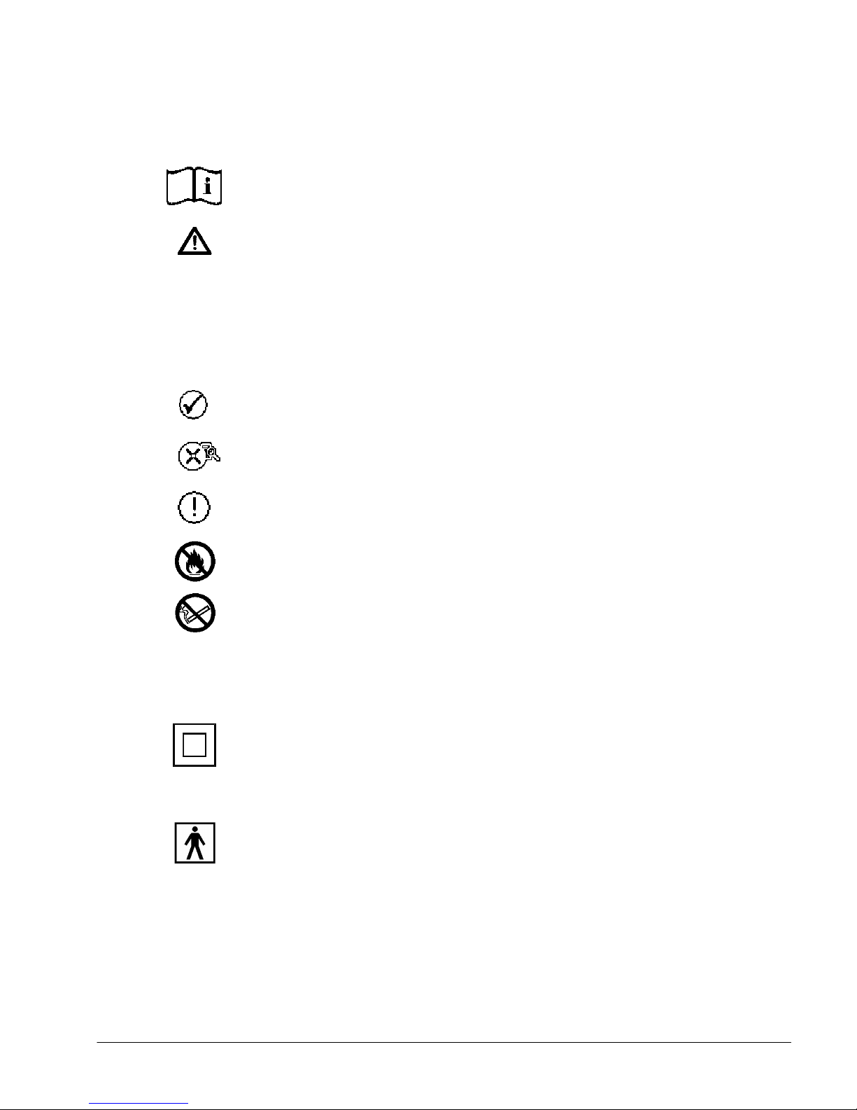
3.6 Symbols and Notations
Consult instructions for use.
Caution!
Note:
Warning! Risk of injury and possible negative patient outcome.
Warns of material damage and negative patient outcome.
Offers useful tips to assist in the proper use of the equipment.
Confirmation Symbol
Invalid Setting Symbol
Conflict Setting Symbol
Keep away from opened flames.
No smoking around ventilator.
IPX4
Ingress protection rating: Splash-proof. Do not immerse.
Class II equipment.
Protection against electric doesn’t rely on Basic Insulation only,
additional safety precautions such as Double or Reinforced
insulation are provided.
Type BF applied part.
e700 User Manual
(15PL1009 - Rev.10 Dec 21, 2016) English version
17
17
1717
Page 19
Chapter 4 Preparation for Use
Battery Stand off
Fig
FigFig
Fig
ure 5
ure 5ure 5
ure 5
Preparation for Use
Preparation for UsePreparation for Use
4.1 Setup
4.1.1 Connecting electrical power supply
The e700 is designed to operate using one of the following power options:
• Internal rechargeable battery pack
• AC to DC external power supply.
Caution:
Caution:
Caution:Caution:
• A fully charged battery must be always installed for safety reasons, even
when operating from an external power supply so that continuous
ventilation is not interrupted in absence of external power.
• The use of batteries other than those specified may cause the ventilator
to fail and/or endanger the patient and operator.
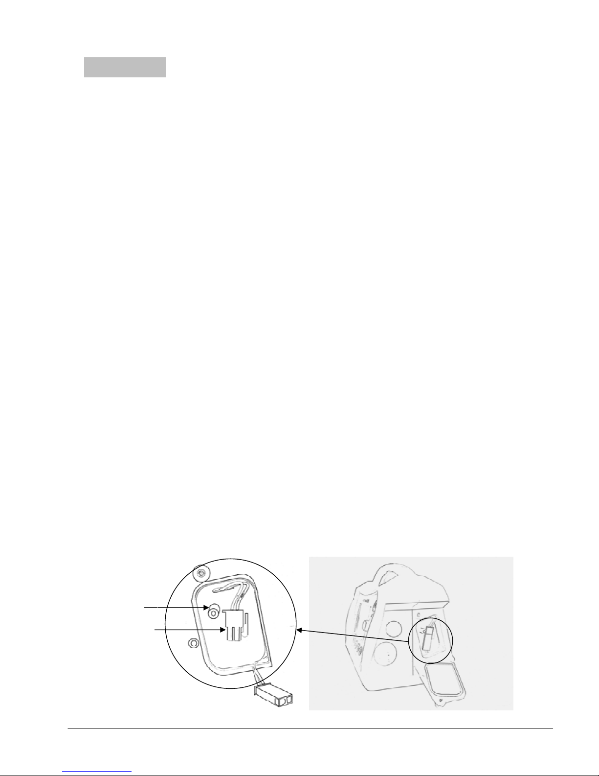
4.1.2 Installing / replacing the battery
1 Make sure the ventilator is turned off and unplugged from mains
electrical supply.
2 Turn screw knob on battery compartment cover anticlockwise to open
the cover downwards.
3 Disconnect the battery leads and pull out the battery pack using its
stand-off. Never pull the battery pack by its leads.
Caution!
Caution!
Caution! Caution!
Always use the battery stand off to pull out the battery pack, never pull the
battery by its leads (Figure 5).
4 Insert the fully charged battery such that the battery stand-off is
positioned upwards (as per illustration below), attach battery
connectors. Close cover and turn screw knob clockwise to secure.
Battery Leads
e700 User Manual
(15PL1009 - Rev.10 Dec 21, 2016) English version
18
18
1818
Page 20

4.1.3 Connecting the Gas Supply
1 Connect the gas supply hose to the gas supply input (T) in Figure 2 of
the e700.
2 Connect the other end of the hose to the pressure outlet of the pressure
regulator or wall outlet of piped medical oxygen system.
3 Turn cylinder valve slowly and fully.
Warning
Warning
WarningWarning
Extra care must be taken when handling oxygen:
o The e700 must only be used with medical oxygen.
o Only use approved medical oxygen compressed gas cylinders.
o Always begin use with a full oxygen cylinder.
o Secure oxygen cylinders so they do not fall over.
o Keep away from excessive heat to avoid the risk of explosion.
o Do not grease or lubricate oxygen fittings, cylinder valves and
pressure reducers, and do not handle with greasy hands to avoid
the risk of fire.
o Only open or close cylinder valves by hand or with the correct
cylinder wrench. Open the valve slowly and fully. Do not use any
other tools.
o Do not smoke or work in areas where open flames are present.
Oxygen supports combustion and exacerbates fires.
o Only use a pressure reducer with an overpressure relief valve to
limit the delivery pressure in case of a regulator failure!
o To avoid ventilator malfunction do not attach the ventilator to a
flow control valve or flow meter.
e700 User Manual
(15PL1009 - Rev.10 Dec 21, 2016) English version
19
19
1919
Page 21

4.1.4 Connecting Patient Circuit
1. Attach the O-Two patient circuit (Figure 3) to 22mm gas output
connector
(S) in Figure 2
.
2. Connect the 2 sensor hoses (V) in Figure 3 of the patient circuit to their
corresponding connectors (Q) & (R) in Figure 2.
3. DO NOT connect the patient circuit to a patient until the ventilator is
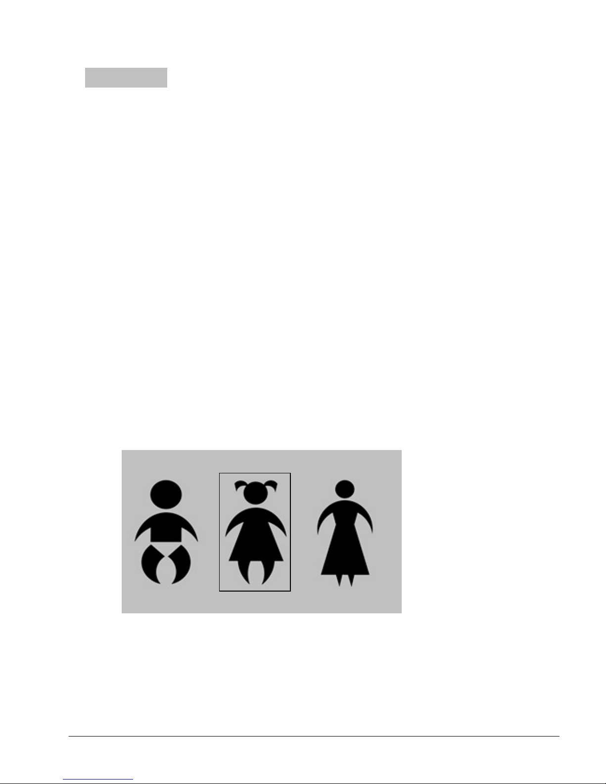
turned on (Step 4.1.5) and three Solid Silhouettes start-up figures
(Shown in Figure 6) are displayed.
4.1.5 Turning Ventilator ON
To turn on the ventilator, Press the ON/OFF button (N) in Figure 1 for one
second. During that second the associated green LED will start blinking at a
high frequency. After 1 second the ventilator will turn on but with no
ventilation at this point.
If the button is pressed and released for less than a second, the ventilator will
remain OFF.
Note
Note:
NoteNote
-
Do not connect the patient circuit to a patient or the test lung before turning
on the ventilator.
- A/C V with volume control (VCV) is the default start-up ventilation mode for
e700.
e700 User Manual
(15PL1009 - Rev.10 Dec 21, 2016) English version
20
20
2020
Page 22

4.2 Pre-use Check
The following check must be performed and confirmed by the Health care provider
in the following cases:
• Prior to use
• After replacing hoses, patient circuits or batteries.
•
At least every 6 months.
1
Visually inspect the ventilator for mechanical damage
2 Ensure that battery is fully charged.
3 Ensure the e700 is connected to a gas supply (Cylinder or piping system)
that delivers a minimum of 45 PSI (3 Bar) and a maximum 87 PSI (6 Bar)
output pressure and a minimum 120 L/min flow
4 Ensure that the patient circuit and monitoring hoses have been properly
connected.
5 Performance check (Leak & Function test):
To undertake the performance check, you will need the following:
• Full Oxygen cylinder.
• Calibrated test lung (Provided with the unit).
• Oxygen pressure regulator capable of delivering flow of 120 L/min and
maintaining a minimum pressure of 45 PSI
PSI
(6 Bar)
output pressure.
a- Connect Input hose to input connector (T) and the other side of input
hose to pressure regulator outlet.
b- Connect power supply to DC input socket.
c- Connect the 2 sensor hoses of patient circuit to sensor connectors #1 (Q)
and #2 (R) and connect the corrugated hose of patient circuit to output
connector (S) (Refer to Figure 2).
d- Once the ventilator is started, connect the other end of patient circuit to
test lung.
Leak Test
Leak Test
Leak TestLeak Test
(3 Bar)
and a maximum 87
Once all connections are verified, slowly and fully turn on the oxygen cylinder
valve. From the pressure regulator gauge reading, ensure cylinder pressure is
above 650 PSI (45 bar) otherwise replace with new oxygen cylinder.
Once pressurized, turn off the oxygen cylinder and observe the pressure
regulator gauge reading. If pressure does not drop more than 0.5 PSI every 30
seconds, the system is free from leaks.
To identify and repair the leak:
To identify and repair the leak:
To identify and repair the leak:To identify and repair the leak:
1- Release the remaining gas from the system.
2- Tighten all connecters firmly.
3- Slowly and fully turn on oxygen cylinder and repeat the above leak test
procedure.
e700 User Manual
(15PL1009 - Rev.10 Dec 21, 2016) English version
21
21
2121
Page 23

4- If leak still present, spray oxygen compatible leak detector on hose and
connectors. Replace input hose or regulator if necessary.
5- Slowly and fully turn on oxygen cylinder.
6- Turn on ventilator and select child default setting.
7- Press and hold manual button (E) and observe the pressure wave form
on the screen. If pressure drops immediately, inspect patient circuit
connections and ensure all connectors are attached. Use leak detector if
needed.
8- Turn off the ventilator and pressure source.
Note:
Note:
Note: Note:
If leak is still present and no external leak was detected using the above
processes, the unit must be returned to the manufacturer or its authorised
service center for service or repair.
Function check
Function check
Function checkFunction check
After confirming no leak is present in the ventilator, with the mains electrical
supply connected, proceed as follows:
1- Turn on the ventilator and select child default setting.
2-
Let the ventilator cycle a few times and during cycling disconnect power
supply, the back up system should switch immediately to internal battery
power. LED indicators should also switch to internal battery.
3-
Check battery level. Do not run the ventilator if battery level is low, install a
fully charged battery.
4-
During ventilator cycling, observe pressure wave and live ventilation
parameters on the screen.
5-
Disconnect the test lung and check for BCI (breathing circuit integrity)
visual alarm associated with yellow warning indicator. BCI audible alarm
associated with red warning indicator must activate in 15 seconds.
6-
Block patient output completely to activate Pmax alarm should be
activated.
7-
Re-connect the test lung, BCI visual and audible alarms should be deactivated.
8-
Change Vt and observe changes on the lung, live ventilation parameters,
and the pressure wave form.
9-
Change Rate and observe changes on the lung, live ventilation parameters
and the pressure wave form.
10-
Change I:E ratio or Ti and observe changes on the lung, live ventilation
parameters and the pressure wave form.
11- Turn off PEEP
parameters and the pressure wave form.
and observe changes on the lung, live ventilation
12- Activate pause, night mode, and flow waveform to ensure proper
functions and screen display.
13- Turn off oxygen cylinder and check for low pressure and no pressure
audible and visual alarms.
14- Turn off Ventilator by pressing ON/OFF button for 4 seconds.
e700 User Manual
(15PL1009 - Rev.10 Dec 21, 2016) English version
22
22
2222
Page 24
Fig
FigFig
Fig
ure 6
ure 6ure 6
ure 6
Chapter 5 Operating
Operating Instructions
OperatingOperating
Instructions
InstructionsInstructions
5.1 Start Up and Setting the Ventilation Parameters
a. Turn on the ventilator:
To turn on the ventilator, press the ON/ OFF button (N) in Figure 1 for
one second. During that second the associated green LED will start
blinking at a high frequency. After 1 second the ventilator will turn on but
with no ventilation at this point. If the button is pressed and released for
Note:
turned on and three Solid Silhouettes figures (Figure 6) are displayed.
less than a second, the ventilator will remain OFF.
Note: Do not connect the patient circuit to a patient before the ventilator is
Note: Note:
b. Start default ventilation:
Once the ventilator is turned on, 3 Solid Silhouettes start-up figures
(Shown in Figure 6) will be displayed on the screen representing Infant,
Child and Adult patient sizes. Each size comes with pre-set parameters
close to the patient’s size to guide the user to select for instant start-up.
This eliminates the need for a potentially long set up before starting
ventilation.
Note:
Note:
Note:Note:
Start-up figures are used during start up only and are not active during
ventilation.
Start
Start----up Figures
up Figures
StartStart
up Figuresup Figures
Healthcare providers navigate among the three start-up figures by
rotating the Control Selection Knob (M) and a square cursor will move
around the selected figure. Once the desired patient size is selected, the
user must confirm the selection by pressing the Control Selection Knob
(M) to start ventilation. If no selection occurs within 20 seconds, the
ventilator will start ventilation with child setting as its default start-up.
e700 User Manual
(15PL1009 - Rev.10 Dec 21, 2016) English version
23
23
2323
Page 25

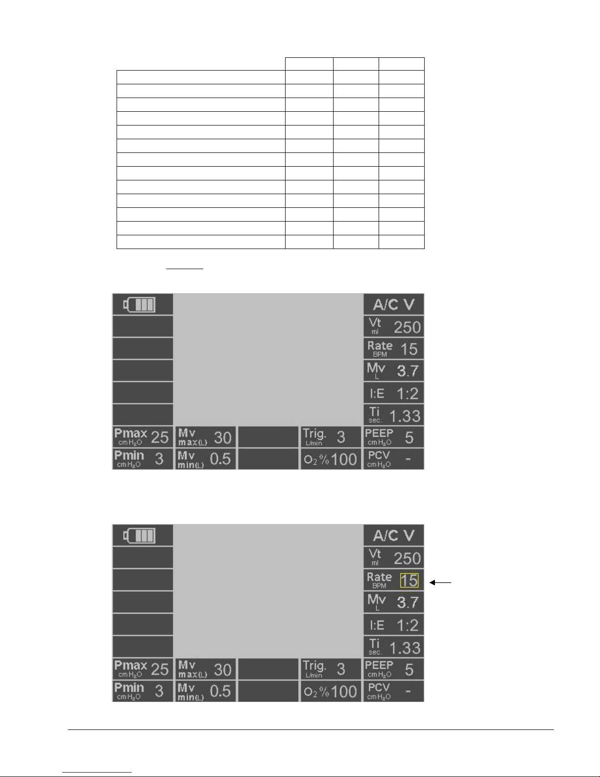
Press the Control Selection Knob (M) to confirm the patient size
selection and connect the patient valve to the patient, the ventilator
starts volume controlled A/C V ventilation with default parameters listed
in Table 1 depending on the selected patient size (Figure 7). User can
also pause the ventilation by pressing Pause/ Resume button (H) until all
desired parameters are selected.
Note:
Note:
Note:Note:
A/C V with volume control is the default start-up ventilation mode.
c. Set up the desired ventilation setting:
Health care providers may choose or change the ventilation mode or
parameter setting any time during ventilation by the following method:
Rotate the Control Selection Knob (M) and move the yellow cursor
(Figure 8) to section 3 of the screen (Figure 4) for ventilation mode
setup, or to the parameter to be set up located at section 6 of the screen
(Figure 4). The user must confirm the selection by pressing the Control
Selection Knob (M). Once confirmed, the selected area will be
highlighted with solid contrast background (Figure 9).
Navigate among the available settings by rotating the Control Selection
Knob (M). Press the Control Selection Knob (M) to choose the desired
setting. The chosen setting will turn yellow with the flashing
confirmation symbol and the Confirmation indicator (L) to guide
users to activate the setup by pressing the Control Selection Knob (M)
again.
Press the Control Selection Knob (M) to activate the setup. Or repeat the
above steps to continue to set up the other parameters. The operator
can also press the Cancel button (K) to go back to previous parameters
before activation. Finally, press the Control Selection Knob (M) to
activate the multiple setting setup at once.
Note:
Note:
Note:Note:
If no selection occurs within 10 seconds or the Control Selection Knob
(M) is not pressed to confirm the changed parameter setting within 10
seconds, changes will be cancelled and the previous parameter values
will remain.
e700 User Manual
(15PL1009 - Rev.10 Dec 21, 2016) English version
24
24
2424
Page 26
AC/V Settings
AC/V SettingsAC/V Settings
AC/V Settings
Infant
InfantInfant
Infant
Child
ChildChild
Child
Adult
AdultAdult
Adult
Rate (BPM)
30 15 10
Vt (ml) 100 250 500
Mv (L)
2
3.7 5
P max (cm H
2
O) 25 25 30
Mv max (L)
30 30 30
Mv min (L)
0.5 0.5 0.5
Ti (Sec.)
1.0 1.33
2.0
I:E 1:2 1:2 1:2
PCV (cm H
2
O) - - -
Figure
FigureFigure
Figure
----
7777
Figure
FigureFigure
Figure
----
8888
Showing frame
(calculated values)
PEEP (cm H2O) 5 5 5
P min (cm H2O) 3 3 3
O2 (%) 100% 100% 100%
F trig. (L/min) 3 3 3
Table
Table----1111
TableTable
A/C V mode default settings
A/C V mode default settings
A/C V mode default settingsA/C V mode default settings
A/C V mode screen w/ default parameters (Child setting)
e700 User Manual
(15PL1009 - Rev.10 Dec 21, 2016) English version
around
Parameter during
selection
25
25
2525
Page 27
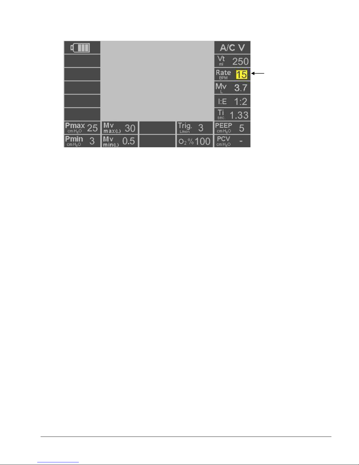
Showing selec
ted
Figure
Figure----9999
FigureFigure
Parameter with
solid contrasting
background
e700 User Manual
(15PL1009 - Rev.10 Dec 21, 2016) English version
26
26
2626
Page 28

5.2 Ventilation Modes
The e700 ventilator is equipped with a number of ventilation modes to enable
the healthcare provider to tailor the ventilator settings to the patient’s specific
respiratory requirements. Ventilation could be delivered invasively (ET tube) or
non-invasively (mask).
In all modes, should the patient demand more flow than set by Health care
provider, he/she can inhale the required volume from ambient.
Each ventilation mode has a default setting (based on the initial patient size
setting selection on startup) which will be initiated on selection of that specific
ventilation mode if no changes to the settings are made.
Note
Notessss
NoteNote
When switching between ventilation modes, any shared parameter will be
carried over and any new parameter will be set to the default.
e700 User Manual
(15PL1009 - Rev.10 Dec 21, 2016) English version
27
27
2727
Page 29
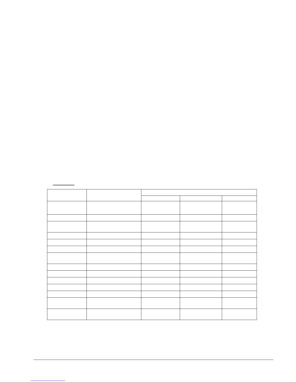
5.2.1 A/C V (Assist Control Ventilation).
Default
DefaultDefault
Default
Tidal
Rate
Vt & f
I:E ratio
Ti*
Trig.
O2
%
Mv max
Mv min
P max.
time only
Table
TableTable
Table
----
2222
Default Ventilation Setting
Default Ventilation SettingDefault Ventilation Setting
Default Ventilation Setting
----
A/C V
A/C V A/C V
A/C V
In this mode the ventilator can deliver volume ventilation (VCV) if Tidal
Volume (Vt) is selected (Figure 10.a) or pressure ventilation (Figure 10.b) if
Pressure Controlled Ventilation (PCV) is selected. Choosing either volume
or pressure ventilation will result in disabling the other parameter (Vt or
PCV). Disabled parameter will be displayed with (-) on the screen.
Volume control ventilation (VCV) with Tidal Volume and ventilation Rate
setting according to patient size is the default start up for this mode (see
Table-2 below).
During A/C V mode, the ventilator will deliver Controlled Mandatory
Ventilation (CMV) regardless of any patient’s effort if the trigger (Trig.) is
disabled (displayed with (-)).
The default trigger for A/C V is 3 L/min but can be adjusted up to 15 L/min.
If no inspiratory effort is detected during the trigger window, the ventilator
will initiate mandatory ventilation at the end of trigger window. Should the
patient demand more flow than set by user, he/she can withdraw the
excess from ambient.
Parameter
Parameter Range
ParameterParameter
Volume
Mv
PEEP
PCV
P min.
Calculated based on
(OFF, 4-20 cm H2O) 5.0 5.0 5.0
(OFF, 4-50 cm H2O)
0-20 cm H2O during I
Manual
Range
RangeRange
(50 - 2000 ml) 100 250 500
(5 - 60 BPM) 30 15 10
(1:4 – 3:1) 1:2 1:2 1:2
(0.2 – 9 sec.) 1.0 1.33 2.0
(OFF, 1 -15 L/min) 3.0 3.0 3.0
(100% or 60% O2) 100 100 100
(2 -40 L) 30 30 30
(0.5 – 35 L) 0.5 0.5 0.5
10 -80 cm H2O 25 25 30
Refer to Manual and
I-Hold section
Infant
Infant Child
InfantInfant
2.0 3.7 5.0
Off, unless
selected
3.0 3.0 3.0
ready ready ready
Child Adult
ChildChild
Off, unless
selected
* Ti may be limited below its range depending on set I:E ratio and rate.
Adult
AdultAdult
Off, unless
selected
e700 User Manual
(15PL1009 - Rev.10 Dec 21, 2016) English version
28
28
2828
Page 30
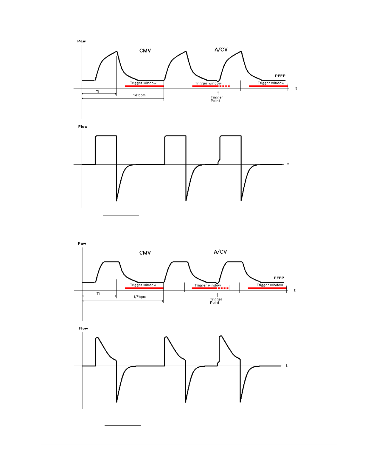
Figure
FigureFigure
Figure
----
10.a
10.a10.a
10.a
A/C V waveform with volume control
A/C V waveform with volume controlA/C V waveform with volume control
A/C V waveform with volume control
Figure
FigureFigure
Figure
----
10.b
10.b10.b
10.b
A/C V waveform with pressure control
A/C V waveform with pressure controlA/C V waveform with pressure control
A/C V waveform with pressure control
e700 User Manual
(15PL1009 - Rev.10 Dec 21, 2016) English version
29
29
2929
Page 31

5.2.2 SIMV (Synchronized Intermittent Mandatory Ventilation).
Default
DefaultDefault
Default
Ti* (0.2 - 9 sec)
1.0 1.33 2.0
In this mode the ventilator will deliver volume ventilation at the set Tidal
Volume (Vt) and Rate (BPM)
The default trigger for this mode is 3 L/min but can be adjusted up to 15
L/min. if trigger condition is met, the ventilator will deliver synchronized
volume controlled mandatory ventilation.
In SIMV mode the selected breathing rate remains constant and the time of
spontaneous breathing window will change if patient triggers the
synchronized mandatory breath before the normal start of inhalation phase
(beginning of Ti).
If no effort was detected during the trigger period, the ventilator will initiate
mandatory ventilation at the end of trigger window. Should the patient
demand more flow than set by user, he/she can withdraw the excess from
ambient.
PSV (Pressure Support Ventilation- Figure 11.b)
PSV is a form of assisted ventilation for the patient who is breathing
spontaneously but whose respirations are insufficient. The ventilator
provides an inspiratory flow based on the patient’s inspiratory effort.
Ventilator sensitivity to the patient’s inspiratory effort is operator adjusted
by using the “Trig.” Control and the inspiratory flow rate is tailored to
patients demand by the ventilator. The point at which the ventilator cycles
off (stated as a percentage of Peak flow) is based on measured airway
pressure and the peak inspiratory pressure and PEEP which are set by the
operator.
Table
Table----3333
TableTable
Default Ventilation Setting
Default Ventilation Setting---- SIMV
Default Ventilation SettingDefault Ventilation Setting
SIMV
SIMVSIMV
Parameter
Parameter
ParameterParameter
Tidal Volume
Rate (5 - 60 BPM) 30 15 10
Mv Calculated based on Vt & f 2.0 3.7 5.0
I:E ratio (1:4 – 3:1) 1:2 1:2 1:2
PEEP (OFF, 4-20 cm H2O) 5.0 5.0 5.0
PSV (OFF, 4-35 cm H2O)
Trig. (1 -15 L/min) 3.0 3.0 3.0
Termination 20-80% of maximum set flow
O2 %
Mv max (2 -40 L) 30 30 30
Mv min (0.5 – 35 L) 0.5 0.5 0.5
P max. 10 -80 cm H2O 25 25 30
P min. 0-20 cm H2O
Manual
Refer to Manual and I-Hold
* Ti may be limited below its range depending on set I:E ratio and rate.
Range
Range
RangeRange
(50 - 2000 ml) 100 250 500
(100% or 60%) 100 100 100
(during I time only)
section
e700 User Manual
Infant
Infant Child
InfantInfant
Off, unless
selected
50% 50% 50%
3.0 3.0 3.0
ready ready ready
(15PL1009 - Rev.10 Dec 21, 2016) English version
Child Adult
ChildChild
Off, unless
selected
Off, unless
selected
Adult
AdultAdult
30
30
3030
Page 32
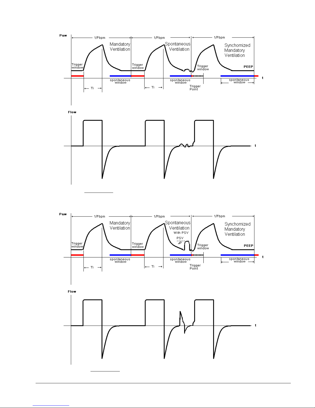
Figure
FigureFigure
Figure
----
11.a
11.a11.a
11.a
SIMV
SIMV SIMV
SIMV
waveform w
waveform wwaveform w
waveform w
/o pressure support
/o pressure support/o pressure support
/o pressure support
Figure
FigureFigure
Figure
----
11.b
11.b11.b
11.b
SIMV
SIMV SIMV
SIMV
waveform w
waveform wwaveform w
waveform w
ith pressure support
ith pressure supportith pressure support
ith pressure support
e700 User Manual
(15PL1009 - Rev.10 Dec 21, 2016) English version
31
31
3131
Page 33

5.2.3 BiLVL (Biphasic Positive Airway Pressure)
Default
DefaultDefault
Default
Rate
(5 - 60
BPM)
30 15 10
selected
selected
selected
Mv max
(2 -40 L)
30 30 30
section
BiLVL mode is similar to SIMV but comes with pressure ventilation. By
setting both inhalation pressure (Pi) and exhalation pressure (PEEP) levels,
the ventilator will deliver pressure controlled mandatory breaths at set
rates (Bpm). The default trigger for spontaneous breathing window is 3
L/min but can be adjusted up to 15 L/min.
Similar to SIMV, in BiLVL mode the selected breathing rate remains
constant and the time of spontaneous breathing window will change
instead if patient triggered the synchronized mandatory ventilation before
the normal start of the inhalation phase (beginning of Ti).
If no effort is detected during the trigger period, the ventilator will initiate
mandatory ventilation at the end of trigger window. Should the patient
demand more flow than set by user, he/she can withdraw the excess from
ambient.
PSV (Pressure Support Ventilation- Figure 12.b)
PSV is a form of assisted ventilation for the patient who is breathing
spontaneously but whose respirations are insufficient. The ventilator
provides an inspiratory flow based on the patient’s inspiratory effort.
Ventilator sensitivity to the patient’s inspiratory effort is operator adjusted
by using the “Trig.” Control and the inspiratory flow rate is tailored to
patients demand by the ventilator. The point at which the ventilator cycles
off (stated as a percentage of Peak flow) is based on measured airway
pressure and the peak inspiratory pressure and PEEP which are set by the
operator.
NOTE:
The peak/plateau pressure is the Pressure Support level plus the PEEP.
Table
Table----4444
TableTable
Default Ventilation Setting
Default Ventilation Setting---- BiLVL
Default Ventilation SettingDefault Ventilation Setting
BiLVL
BiLVLBiLVL
Parameter
Parameter
ParameterParameter
Pi (OFF, 4-50 cm H2O) 15 15 15
PEEP (OFF, 4-20 cm H2O) 5 5 5
I:E ratio (1:4 – 3:1) 1:2 1:2 1:2
Ti* (0.2 - 9 sec) 1.0 1.33 2.0
PSV (OFF, 4-35 cm H2O)
Trig. (1 -15 L/min) 3.0 3.0 3.0
Termination 20-80% of maximum set flow 50% 50% 50%
O2 %
Mv min (0.5 – 35 L) 0.5 0.5 0.5
P max. 10 -80 cm H2O 25 25 30
P min. 0-20 cm H2O
Manual
(100% or 60% O2) 100 100 100
Refer to Manual and I-Hold
* Ti may be limited below its range depending on set I:E ratio and rate.
Range
Range
RangeRange
(during I time only)
e700 User Manual
Infant
Infant Child
InfantInfant
Off, unless
3.0 3.0 3.0
ready ready ready
(15PL1009 - Rev.10 Dec 21, 2016) English version
Child Adult
ChildChild
Off, unless
Off, unless
Adult
AdultAdult
32
32
3232
Page 34
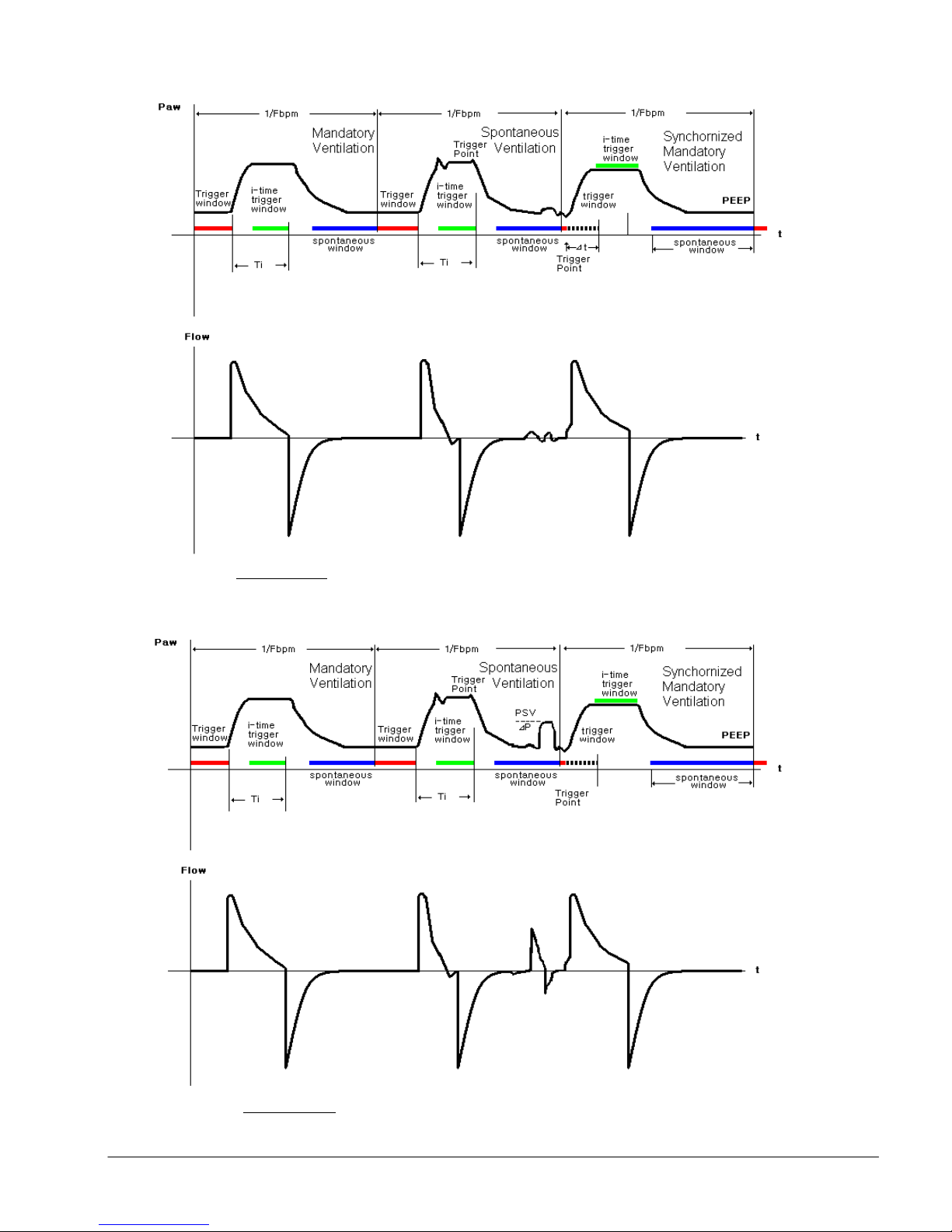
Figure
FigureFigure
Figure
----
12.a
12.a12.a
12.a
BiLVL
BiLVL BiLVL
BiLVL
waveform w
waveform wwaveform w
waveform w
/o pressure support
/o pressure support/o pressure support
/o pressure support
Figure
FigureFigure
Figure
----
12.b
12.b12.b
12.b
BiLVL
BiLVL BiLVL
BiLVL
waveform w
waveform wwaveform w
waveform w
ith pressure support
ith pressure supportith pressure support
ith pressure support
e700 User Manual
(15PL1009 - Rev.10 Dec 21, 2016) English version
33
33
3333
Page 35

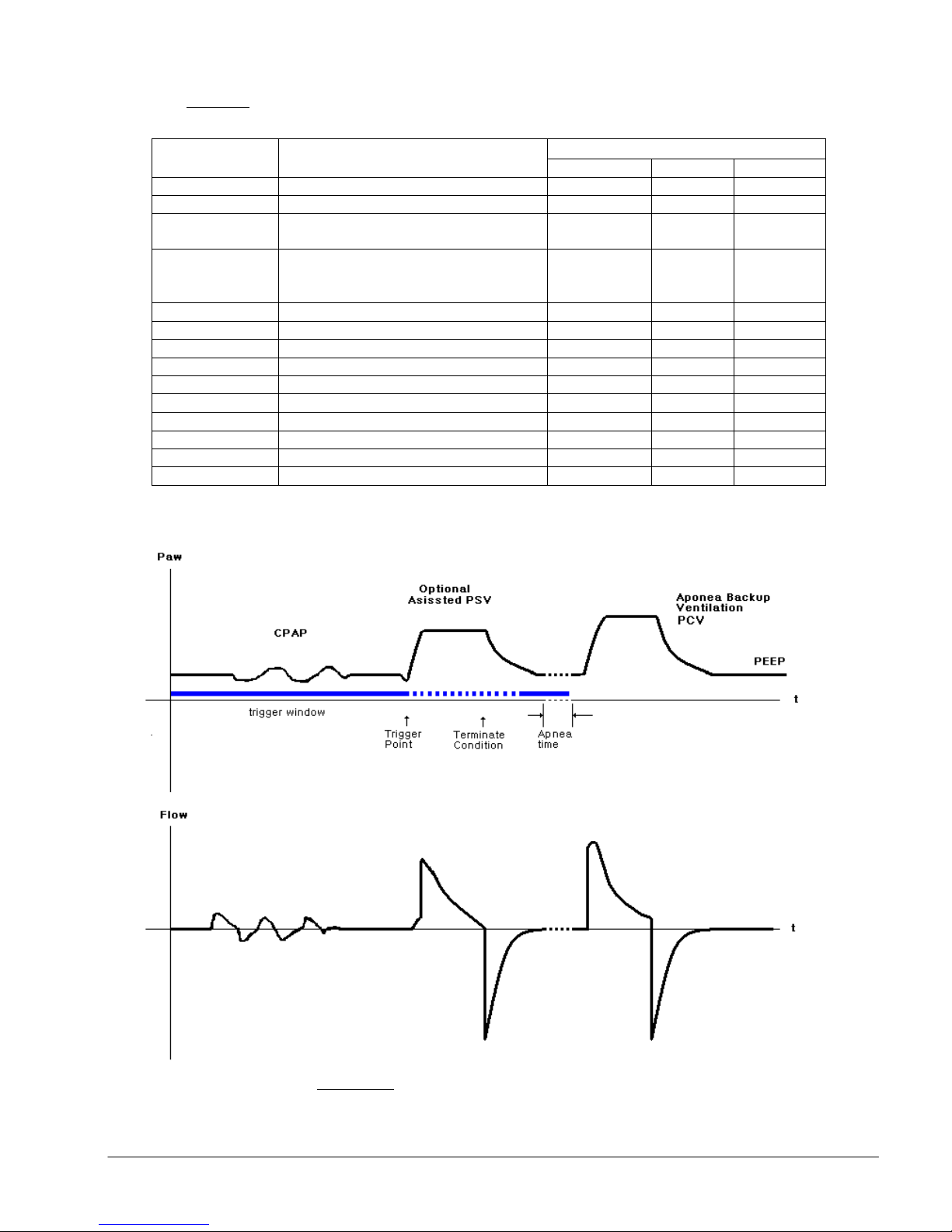
5.2.4. CPAP (Continuous Positive Airway Pressure)
In CPAP mode, the ventilator will deliver a continuous flow rate to generate
airway pressure and use the control valve to maintain CPAP levels (Figure
13).
There are 2 breathing modes available for the patient during CPAP. The first
mode is with spontaneous breathing when the optional pressure support is
set to “-”. In this option the ventilator adjusts the amount of flow internally
to maintain average airway pressure close to CPAP setting.
The other mode is when the optional PSV (Pressure Support) is set to a
desired value. The ventilator will deliver the set PSV pressure starting at
triggering point and until the exhalation phase starts.
NOTE:
The d
The default trigger in CPAP mode is pressure t
The dThe d
2 cm
2 cm HHHH
2 cm2 cm
The CPAP mode is equipped with APNEA back up ventilation in which the
ventilator switches to Assist Control ventilation (A/C V) when the ventilator
does not trigger patient’s spontaneous breathing for a period of time (T
APNEA) set by the user. The parameters of back up A/C ventilation are
defaulted to volume ventilation based on the initial start up patient size
selection unless changes are made by the user.
The trigger changes from pressure trigger (P) to 3 L/min default flow
trigger when the ventilator switches to APNEA back up.
PSV (Pressure Support Ventilation)
PSV is a form of assisted ventilation for the patient who is breathing
spontaneously but whose respirations are insufficient. The ventilator
provides an inspiratory flow based on the patient’s inspiratory effort.
Ventilator sensitivity to the patient’s inspiratory effort is operator adjusted
by using the “Trig.” Control and the inspiratory flow rate is tailored to
patients demand by the ventilator. The point at which the ventilator cycles
off (stated as a percentage of Peak flow) is based on measured airway
pressure and the peak inspiratory pressure and PEEP which are set by the
operator.
NOTE: The peak/plateau pressure is the Pressure Support level plus the
PEEP.
efault trigger in CPAP mode is pressure trigger (P
efault trigger in CPAP mode is pressure tefault trigger in CPAP mode is pressure t
O below CPAP settings.
O below CPAP settings.
O below CPAP settings.O below CPAP settings.
2222
rigger (P) which is set at
rigger (Prigger (P
) which is set at
) which is set at ) which is set at
e700 User Manual
(15PL1009 - Rev.10 Dec 21, 2016) English version
34
34
3434
Page 36
Table
Default
DefaultDefault
Default
CPAP
(4-
20 cm H
2
O) 5 5 5
Mv (A)
Will be c
alculated based on Vt & f
2.0 3.7 5.0
P max.
10 -80 cm H
2
O 25 25 30
Figure
FigureFigure
Figure
----
13
1313
13
CPAP ventilation
CPAP ventilation CPAP ventilation
CPAP ventilation
waveform
waveformwaveform
waveform
Table----5555
TableTable
Parameter
Parameter Range
ParameterParameter
PSV (OFF, 4-35 cm H2O) OFF OFF OFF
Trig.
Termination
O2 %
T APNEA (10-60 seconds) 20 20 20
Vt(A) (50 - 2000 ml) 100 250 500
Rate (A) (5 - 60 BPM) 30 15 10
I:E ratio (A) (1:4 – 3:1) 1:2 1:2 1:2
Mv max (2 -40 L) 30 30 30
Mv min (0.5 – 35 L) 0.5 0.5 0.5
P min. 0-20 cm H2O during I time only 3.0 3.0 3.0
Default Ventilation Setting
Default Ventilation Setting---- CPAP
Default Ventilation SettingDefault Ventilation Setting
Range
RangeRange
(P or 1 -15 L/min)
P = 2 cm H2O below base line
(20 – 80 % of maximum set flow)
or 2 cm H2O below baseline in
CPAP mode only
(100% or 60%) 100% 100% 100%
CPAP
CPAPCPAP
Infant
Infant Child
InfantInfant
P P P
50 % 50% 50%
Child Adult
ChildChild
Adult
AdultAdult
e700 User Manual
(15PL1009 - Rev.10 Dec 21, 2016) English version
35
35
3535
Page 37
Default
DefaultDefault
Default
5.2.5 CPR mode
The CPR mode consists of timed chest compression audible prompts
coupled with automatically delivered breaths for both intubated and mask
ventilated patients. There is also a visual animated display to guide the
health care provider while performing CPR.
The CPR mode for masked ventilated patients is the default setting for this
mode but changes can be made between the 2 sub-modes at any time.
The CPR mode for masked ventilated patients consists of 2 phases, chest
compression and ventilation. 30 chest compressions over 18 seconds are
synchronized with audible prompts and on screen visual animations,
followed by two, 1 second, mandatory breaths within a 5 second ventilation
phase. The ratio between chest compressions and ventilations is 30:2.
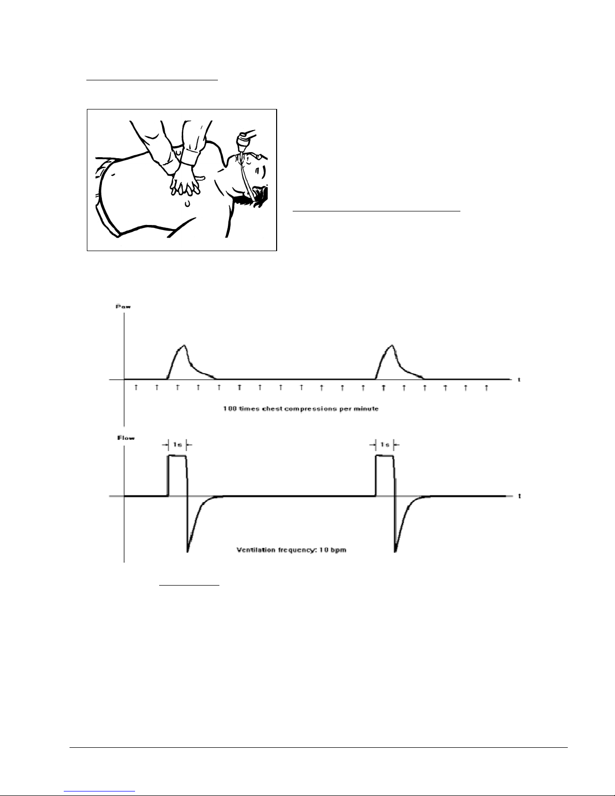
The CPR mode for intubated patients consists of continuous compressions
indicated by an audible prompt and visual animation at a rate of 100
compressions per minute plus automatically delivered breath every 6
seconds (10 BPM).
The default ventilation in CPR mode is flow controlled ventilation. The
default tidal volume is set according to the initial start-up patient size
selection when switching to CPR mode but could be adjusted to desired
values. Optional pressure controlled ventilation is provided by setting the
PCV pressure parameter. If PCV parameter is selected, the flow controlled
ventilation will be disabled. The FiO2 is fixed at 100% oxygen during CRP
mode.
The ventilator will automatically compensate up to 30% of the required tidal
volume Vt in case a leak is detected. Beyond this limit, low Paw visual and
audible alarms will be activated to warn rescuer to either re-apply the mask
or increase the set tidal volume.
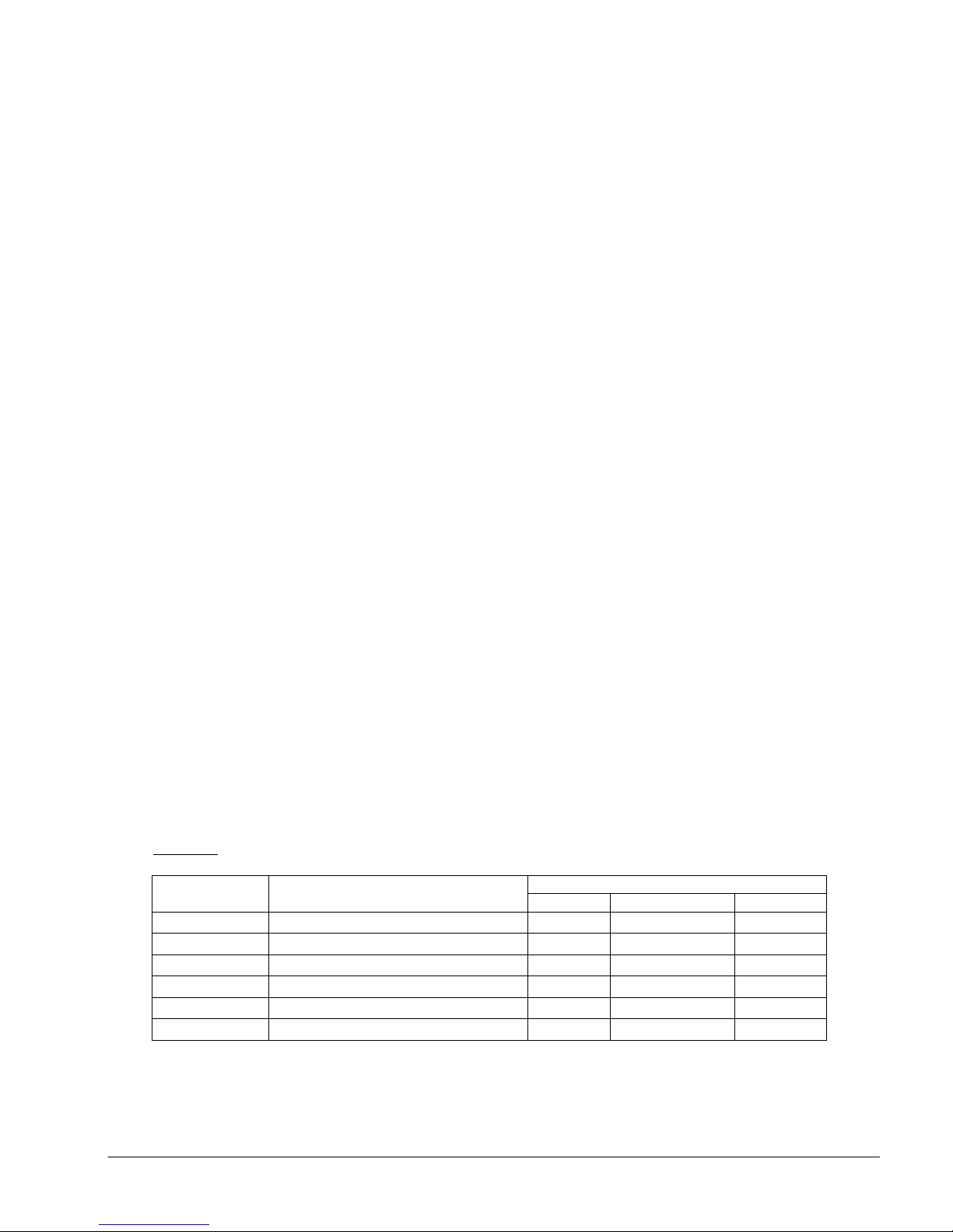
Table
Table----6666
TableTable
Tidal Volume (50 - 1400 ml) 100 250 500
PCV (OFF, 4-50 cm H2O) OFF OFF OFF
Mv max (2 -40 L) 30 30 30
Mv min (0.5 – 35 L) 0.5 0.5 0.5
P max.
P min. (0-20 cm H2O during I time only) 3 3 3
Default Ventilation Setting
Default Ventilation Setting---- CPR
Default Ventilation SettingDefault Ventilation Setting
Parameter
Parameter Range
ParameterParameter
Range
RangeRange
(10 -80 cm H2O) 40 40 60
CPR
CPRCPR
Infant
Infant Child
InfantInfant
Child Adult
ChildChild
Adult
AdultAdult
e700 User Manual
(15PL1009 - Rev.10 Dec 21, 2016) English version
36
36
3636
Page 38
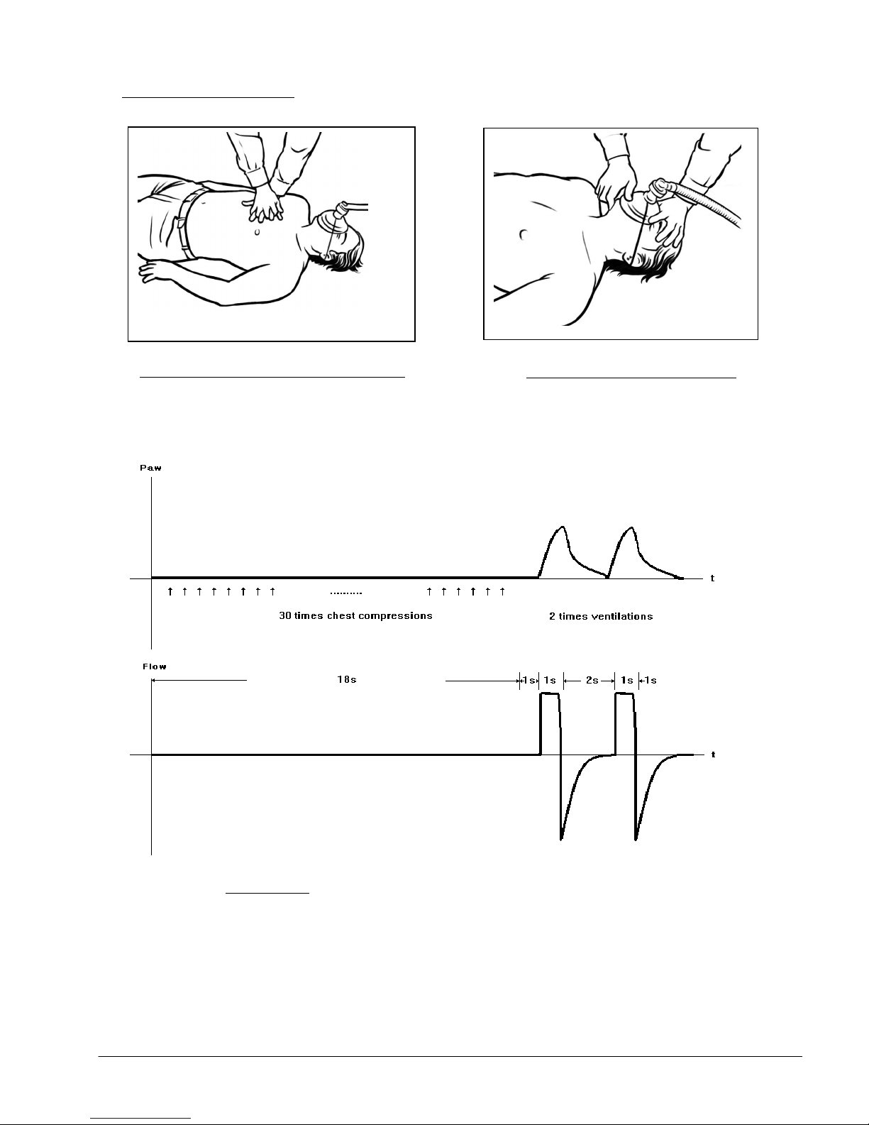
CPR for masked patients
On screen chest compressing animation
CPR for masked patients
CPR for masked patientsCPR for masked patients
Figure
Figure----14.a
FigureFigure
14.a CPR
14.a14.a
CPR waveform
waveform for masked patient
CPR CPR
waveform waveform
for masked patient
for masked patientfor masked patient
On screen ventilation animation
e700 User Manual
(15PL1009 - Rev.10 Dec 21, 2016) English version
37
37
3737
Page 39
Figure
FigureFigure
Figure
----
14.b
14.b14.b
14.b
CPR
CPR CPR
CPR
waveform
waveform waveform
waveform
for intubated patient
for intubated patientfor intubated patient
for intubated patient
CPR for intubated patients
CPR for intubated patients
CPR for intubated patients CPR for intubated patients
On screen intubated CPR animation
e700 User Manual
(15PL1009 - Rev.10 Dec 21, 2016) English version
38
38
3838
Page 40

5.3 Turning the Ventilator Off
Press and hold the ON/OFF button for 4 seconds, the Ventilator will turn OFF.
e700 User Manual
(15PL1009 - Rev.10 Dec 21, 2016) English version
39
39
3939
Page 41

Chapter 6 Post U
6.1 Disconnect Device After Use
a. Turn off gas supply to the ventilator.
b. Disconnect gas supply hose.
c. Disconnect patient circuit from the output connector.
d. Unplug the power cable from mains if no charging is required.
e. Clean and disinfect according to section 8.1 in this manual
6.2 Storage
Store ventilator within the following environmental range:
- 40oC to +60oC, Rh: 15% to 95%.
Post Use
Post UPost U
se
sese
e700 User Manual
(15PL1009 - Rev.10 Dec 21, 2016) English version
40
40
4040
Page 42

Chapter 7 AAAAlarms and Indicators
larms and Indicators
larms and Indicatorslarms and Indicators
7.1 Ventilation Alarms
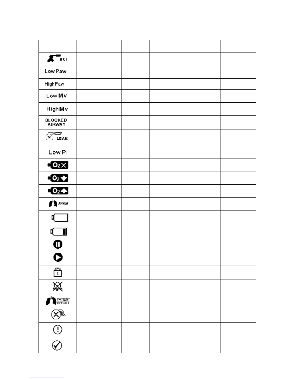
Visual and Audible alarms continue until the cause of the alarm is resolved.
During alarm activation the user may press the Alarm Silence button (G) in
Figure 1 which will silence the audible alarm for 2 minutes but the visual alarm
will continue to flash until the cause of the problem is resolved.
During “alarm silence”, should a new alarm develop, the Alarm Silence function
will continue and only the new alarm will be shown flashing on the screen.
Alarms will be visible in section 4 or section 7 of the display (Figure 4).
There could be multiple alarm/warning symbols visible on the screen
indicating multiple failures occurring at the same time. In this case the visible
and audible alarms will be based on highest priority alarm.
All ventilation alarms of e700 are listed in the following Table-7.
e700 User Manual
(15PL1009 - Rev.10 Dec 21, 2016) English version
41
41
4141
Page 43
Table
Patient Circuit
Flashing Yellow for
15 sec. delay
Two
Solid symbol
Table----7777 Ventilation Alarms
TableTable
Symbol
Symbol Name
SymbolSymbol
Ventilation Alarms
Ventilation AlarmsVentilation Alarms
Name Priority
NameName
disconnect (Breathing
circuit Integrity)
Low Airway Pressure High
High Airway Pressure High
Low mi nute Volume High
High Minute Volume High
Priority
PriorityPriority
High after 15
seconds
Visual Alarm
Visual Alarm
Visual AlarmVisual Alarm
Alarm symbol
Alarm symbol Warning LED
Alarm symbolAlarm symbol
Flashing
symbol
Flashing
symbol
Flashing
symbol
Flashing
symbol
Flashing
symbol
Warning LED
Warning LED Warning LED
15 seconds then
Red
Red
Red
Red
Red
Audible
Audible
Audible Audible
Alarm
Alarm
AlarmAlarm
bursts with five
pulses
Two bursts with
five pulses
Two bursts with
five pulses
Two bursts with
five pulses
Two bursts with
five pulses
Blocked airway
Leak (at 40%
below set Vt)
Low Inhalation
Pressure
No Oxygen
≤ 20 PSI
Low Oxygen
≤ 40 PSI
High input pressure
≥ 90 PSI
APNEA High
Empty Battery
Low Battery
Pause N/A
High
High
High
High
Medium
High
Play N/A
High
Low
Flashing
symbol
Flashing
symbol
Flashing
symbol
Flashing
symbol
Flashing
symbol
Flashing
symbol
Flashing
symbol
Flashing
symbol
Flashing
symbol
Flashing
symbol
Flashing
symbol
Red
Red
Red
Red
Yellow
Red
Red
Red
N/A N/A
Yellow every 15
seconds
N/A N/A
Two bursts with
five pulses
Two bursts with
five pulses
Two bursts with
five pulses
Two bursts with
five pulses
One burst with
three pulses
Two bursts with
five pulses
Two bursts with
five pulses
Two bursts with
five pulses
N/A
Lock N/A Solid symbol N/A N/A
Alarm Silence N/A Solid symbol N/A N/A
Patient effort Low
Invalid setting- Refer
to manual
Setting Conflict N/A
Confirm
during Patient
N/A
Solid symbol
During invalid
Solid symbol
During invalid
Flash symbol
N/A
after primary
e700 User Manual
effort
selection
N/A N/A
N/A N/A
N/A N/A
selection
selection
(15PL1009 - Rev.10 Dec 21, 2016) English version
N/A N/A
42
42
4242
Page 44
7.2 Battery Status Indicator
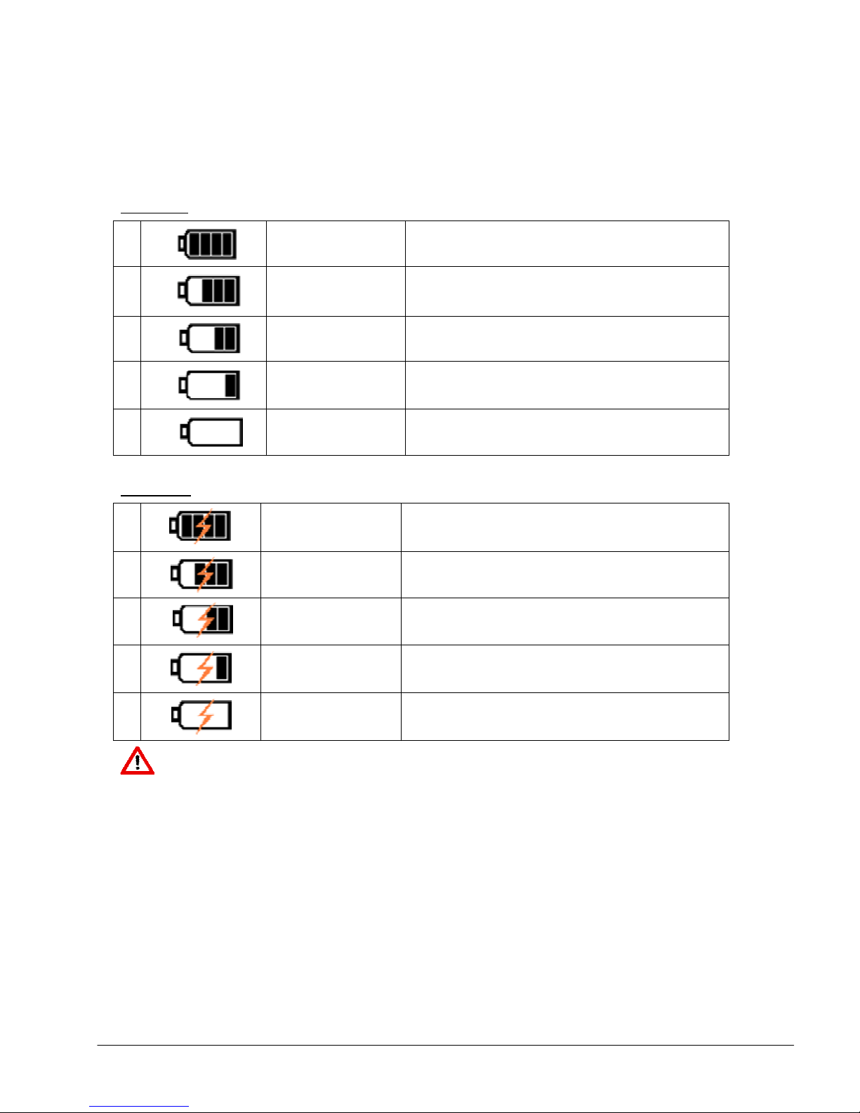
Battery status will be displayed in section 1 of the display (Figure 4). There are
two different status indicators showing battery discharging (Table-8.1) and
charging (Table-8.2) status respectively.
Tab
Table
le----8.1
8.1 Battery discharg
TabTab
lele
Battery discharging
8.18.1
Battery dischargBattery discharg
ing status
status
inging
statusstatus
1
2
3
4
5
Table
Table----8.2
TableTable
1
2
3
8.2 Battery
8.28.2
Full Capacity No Alarm
Approx. 75% of full
Approx. 50% of
Approx. 25% of full
Approx. 5% of full
Battery charg
Battery Battery
charging
chargcharg
Full Capacity No Alarm
capacity
full capacity
capacity
capacity
ing status
status
inging
statusstatus
95% of full
capacity
90% of full
capacity
No Alarm
No Alarm
On screen symbol change to Yellow color and
flashing
On screen symbol change to Red color and
flashing with associated Red color warning LED.
No Alarm
No Alarm
4
5
Warning
Warning
WarningWarning
80% of full
capacity
65% of full
capacity
No Alarm
No Alarm
At approximately 2% of full battery capacity, the ventilator will not start
when it is turned off or will shut down when it is turned on.
Note:
Battery capacity levels are detected from measured voltages and the
capacities shown above are based on results from new batteries tested at
room and low temperature. Battery capacity levels are subject to change when
old batteries are used.
Fully charged Batteries shall be recharged after 6 months without usage or
when battery discharging LED turns orange and flashing. Battery Re-charging
time is about 5.5 hours from fully discharged. Batteries have a minimum of 200
discharge and charge cycles.
43
43
4343
e700 User Manual
(15PL1009 - Rev.10 Dec 21, 2016) English version
Page 45
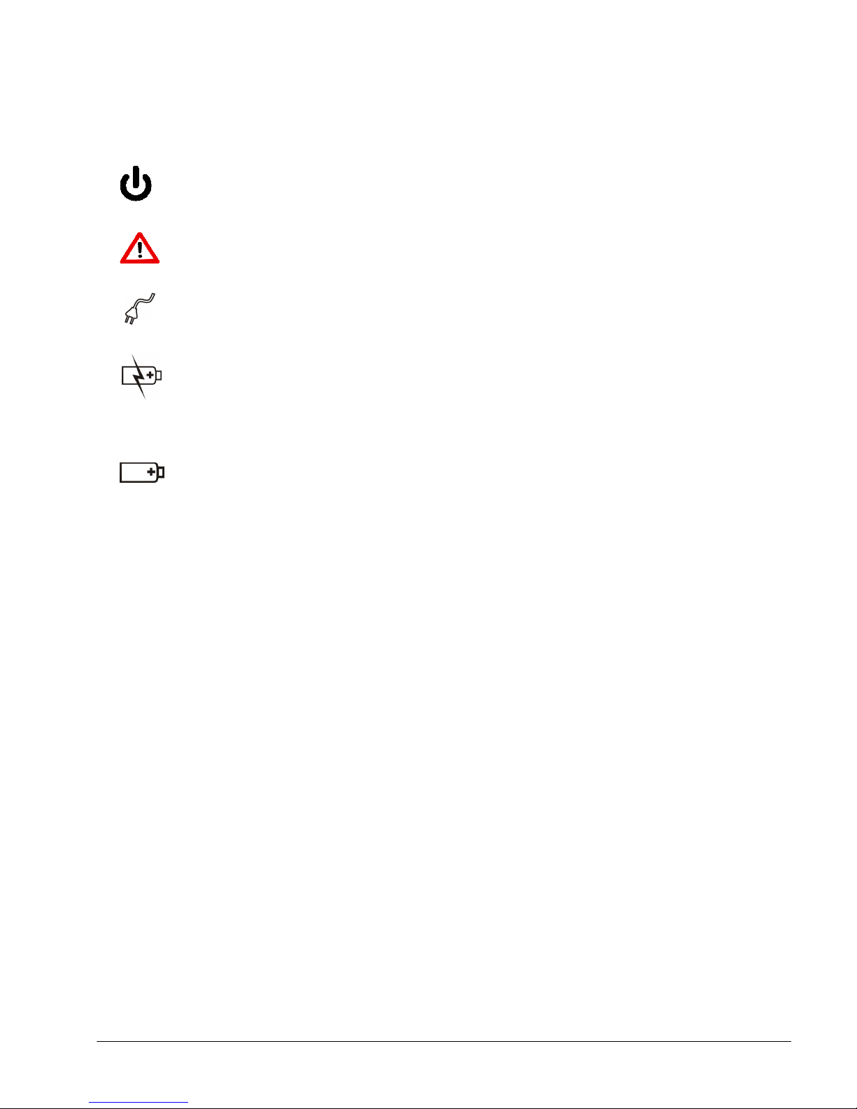
Green color LED
- Continuous when unit is ON and flashing
7.3 LEDs
when unit is OFF.
Red or Yellow color LED – Flashing during alarm/ warning situation.
LED color depends on the severity of the failure.
Green color LED - Continuous when unit is connected to AC power
source during both ON and OFF phases.
Orange color LED - Continuous when unit is charging and off when
battery is fully charged during both ON and OFF phases.
During OFF phase this light will start flashing when battery capacity
drops to around 90 %.
Green color LED - Continuous when unit is operated using internal
battery.
e700 User Manual
(15PL1009 - Rev.10 Dec 21, 2016) English version
44
44
4444
Page 46
Chapter 8 Cleaning
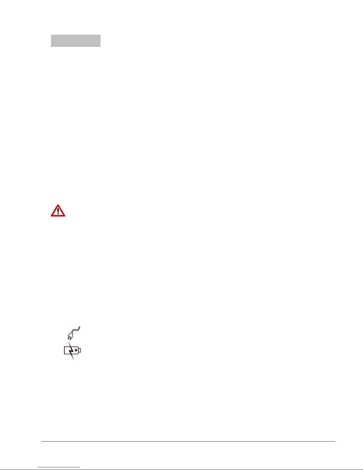
Green LED
- Continuous when unit is connected to external power
Orange LED
- Continuous when unit is charging and off when
battery is fully charged during both ON and OFF phases.
Cleaning,
CleaningCleaning
, Maintenance
, ,
Maintenance &&&& SSSServicing
MaintenanceMaintenance
ervicing
ervicingervicing
8.1 Cleaning and Disinfection
Disinfect the ventilator housing and supply hose using a damp cloth with a
commercially available, legally marketed disinfectant solution which is
compatible with the materials of manufacture in accordance with local
protocols. Do not use chlorine based cleaning agents. Make sure no liquids
enter the ventilator connections or the ventilator.
Do not immerse the e700 Ventilator or patient circuit or supply hoses in
disinfectant or other liquids, serious electric shock hazard and damage to the
ventilator may occur. If the Ventilator is accidently submerged in any liquid it
must be returned to the manufacturer for factory service.
Do not attempt to clean intake filter or patient circuit. Using a wet or damp
filter may result in inaccurate parameters and potentially damage the
ventilator.
Warning
Warning
Warning Warning
Risk of Explosion!
Risk of Explosion!
Risk of Explosion!Risk of Explosion!
Cleaning agents containing alcohol or grease become flammable when
combined with compressed oxygen and can cause explosions.
8.2 Charging the battery
1. Connect one end of the external power supply/charger to its supply
(100 to 240 Volts or on-board vehicle socket) and the other end to the
DC input socket (O) in Figure 2 located on the side panel of the
ventilator. The indicator lights up as follows:
source during both ON and OFF phases
2. Turn unit ON and observe battery level (section 1 of the screen), Refer
to 7.2 Battery Status Indicator for exact battery charging status. The
battery shall be fully charged.
Caution
Caution
CautionCaution
The ambient temperature shall be between 0 oC and 35 oC during battery
charge.
.
e700 User Manual
(15PL1009 - Rev.10 Dec 21, 2016) English version
45
45
4545
Page 47
Notes
Charging
User Manual
Battery fully
Every 6
User Manual
Every 6
Function
User Manual
No abnormal
Every 6
Manufacturer
Notes
NotesNotes
The Battery pack can be charged during operation.
The Battery pack may be charged using external power supply
supplied with the unit or the optional DC to DC power supply.
The Battery pack should be replaced after 200 charge/discharge
cycles or if the battery pack will not fully charge (as indicated on the
battery display on the ventilator) or if the ventilator doesn’t run for
more than 5 hours on a single charge.
8.3 Ambient Air Entrainment Filter
The e700 entrains ambient air through the internal Venturi system for
ventilation when the O2 concentration is set at 60%. This provides not only
decreased oxygen concentration but also increases the ventilator operating
time on an oxygen cylinder.
Caution
Caution
CautionCaution
Always keep the ambient air entrainment port clear of obstructions. Always
replace the filter after use.
Warning
Warning
WarningWarning
Avoid particulate and/or gaseous pollutants in the ambient air! The
entrainment of pollutants into the ventilator may cause the ventilator to
malfunction or cause danger to the patient.
8.4 Preventive Maintenance and Servicing
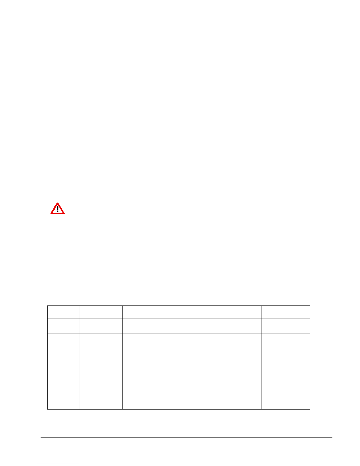
It is recommended that routine preventive maintenance (PM) and
servicing shall be carried out as per the following:
Type
Type Description
TypeType
PM
PM
PMPM
PM
PM Leak test
PMPM
PM
PM
PMPM
Servicing
Servicing
ServicingServicing
Description
DescriptionDescription
battery
check
Level II
service
Procedure
Procedure Criteria
ProcedureProcedure
Chapter 8.2
Chapter 4.2
Chapter 4.2
Service
manual
Criteria Schedule
CriteriaCriteria
charged
No leak observed
function observed
Meet product
specifications
Schedule
ScheduleSchedule
months
months
months
Every 2
years
By
By
ByBy
User
User
User
or authorized
service center
Servicing
Servicing
ServicingServicing
Full service
Service
manual
e700 User Manual
Meet product
specifications
(15PL1009 - Rev.10 Dec 21, 2016) English version
Every 6
years
Manufacturer
46
46
4646
Page 48

Preventive Maintenance
Preventive Maintenance
Preventive Maintenance Preventive Maintenance
To ensure proper operation of the ventilator, regular inspection and checking
of the device and accessories for correct function should be undertaken by a
responsible member of staff. It is recommended that a preventive maintenance
record be maintained for each unit.
The battery should be charged and the ventilator be checked for leakage and
proper function at least every six months, and more frequently in high use
applications. Any malfunction unit should be returned to the manufacturer or
an authorized service center since this product is not designed for field
disassembly or service. Unauthorized repairs will nullify the product warranty.
Level II service
Level II service
Level II serviceLevel II service
The device shall be returned to the manufacturer or a service center
authorized by the manufacturer for bi-annual Level II service every 2 years.
Manufacturer full service
Manufacturer full service
Manufacturer full serviceManufacturer full service
The device shall be returned to O-Two Medical Technologies for Manufacturer
Full Service every 6 years.
Warning
Warning
WarningWarning
Any malfunction unit should be returned to the manufacturer or an authorized
service center since this product is not designed for field disassembly or
service.
e700 User Manual
(15PL1009 - Rev.10 Dec 21, 2016) English version
47
47
4747
Page 49
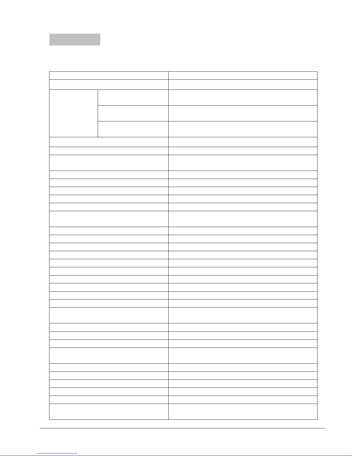
Chapter 9 Technical Data
FEATURES
FEATURESFEATURES
FEATURES
e700
e700 e700
e700
Protection against
Protection against
Circuit Control Source
Electric
A/C
A/CA/C
A/C
(VCV,PCV),
SIMV
SIMVSIMV
SIMV
w/ PSV,
BiLVL
BiLVLBiLVL
BiLVL
w/ PSV,
Supporting ventilation
PSV: 0, 4
-
35 cm.H2O
Ventilation
Rate
5 – 6
0
Minute Volume (L)
Calculated
Tidal Volume (ml)
50 –
2000
BTPS *
Yes, set flow rate or pressure will be
Maximum Inspiratory hold time
6
sec.
I:E Ratio
1:4 – 3:1
PSV
OFF, 4
– 35
O2 (%)
60 or 100
Pmin (cm H
2
O) 0 –
20
PCV (cm H
2
O) 4-50
Ti (sec.)
0.2 – 9
1 -15, or 2
cm.
H2O below baseline in CPAP
Inhalation Pressure (cm H
2
O) 4-50
APNEA back up time (sec.)
10-
60
Battery Operating time at
room
>
18 hrs for default settings
(Data obtained
Altitude compensation
up to 4000m (13000 feet)
Battery Hot Swap
No
Built
-
in Battery charger
Yes
AC/DC power supply
100
-
240VAC/ 19VDC, 4.74
A
Patient
circuit
O-
Two Electronic Ventilator Circuit
Mounting brackets for road ambulance and
Technical Data
Technical DataTechnical Data
9.1 Specifications
Device class per MDD II b
Class II
Type BF
IP X4
Classification
per
IEC60601-1
electric shock
Protection against
electric shock
water
Power Source Compressed Oxygen, 45 to 87 PSI (3-6 Bar)
Ventilation modes
Tidal Volume in CPR mode (ml) 50 - 1400
Manually triggered Ventilation
PEEP (cm H2O) 0,4-20
CPAP (cm H2O) 4-20
Pmax (cm H2O) 10 – 80
CPAP
CPAP w/ PSV, Mask CPR
CPAPCPAP
CPR and Intubated CPR
CPRCPR
(± 10% or ± 2 cm.H2O)
(± 10% or ± 1BPM)
± (4ml + 15%)
± (4ml + 15%)
BTPS *
delivered during I time then Inspiratory hold
(± 20%)
(± 10% or ± 2 cm.H2O)
(± 10% or ± 2 cm.H2O)
(± 10% or ± 2 cm.H2O)
(± 15%)
(± 10% or ± 2 cm.H2O)
(± 10% or ± 2 cm.H2O)
(± 10% or ± 2 cm.H2O)
(± 20%)
Trigger sensitivity (L/min)
Pressure ventilation Termination 20% - 80% of max. Flow
temperature (hrs.)
Mounting Bracket
e700 User Manual
mode only
(± 10% or ± 2 cm.H2O)
(± 0.5s)
using fully charged new battery)
mobile setting
(15PL1009 - Rev.10 Dec 21, 2016) English version
48
48
4848
Page 50

Display 4.3" Color TFT
Mve,Vte
,Paw
,PAW
, Rate
(bpm
),
Parameter settings
Control Selection Knob
Gas Supply Pressure
Yes
Airway Pressure limits
Yes
Battery status
Yes
Breathing Circuit Integrity
Yes
Audible silence
Yes, 120 second max
Dimensions (mm)
250 x 200 x 155
Weight (Kg)
with Battery
y
2.4
D
ead space of patient valve with
Compliance (disposable) hose
Live monitoring
(AV)
Battery level
(Peak)
Real time waveform Pressure or Flow
DAY/NIGHT display mode Yes
Lock key function Yes
Pause function Yes
Noise level in normal use Less than 65 dBA
Alarms (Visual and Audible)
Alarms (Visual and Audible)
Alarms (Visual and Audible)Alarms (Visual and Audible)
Minute Volume limits
APNEA
Leakage and Blockage
w/o Batter
Internal Volume of the complete
respiratory system (reusable and
disposable)
approx. 690 ml without mask
approx. 800 ml with mask
Yes
Yes
Yes
1.77
elbow
system
Resistance of Patient Hose system
(Inhalation and Exhalation):
Operating
Less than 6 cmH2O at 60 l/min & Less than
- 18oC to +50oC, Rh: 15% to 95%
Approx. 35 ml
16.6 ml/Kpa
6 cmH2O at 30 l/min
Ventilator
Storage - 40oC to +60oC, Rh: 15% to 95%
Charge 0oC to +40oC
Environment
condition
* BTPS: Volume measurements corrected to Body temperature 37 oC and Barometric
pressure 101.3Kpa under saturated conditions (100% Humidity).
Note: Measurement uncertainty: 5% for volume parameters and 6% for pressure
parameters.
Battery
Pack
Patient
Circuit
Discharge
Storage
Operating
- 20oC to +35oC, low humidity and no
- 18oC to +50oC, Rh: 15% to 95%
- 20oC to +60oC
corrosive gas atmosphere.
Storage - 20oC to +60oC, Rh: 15% to 95%
e700 User Manual
(15PL1009 - Rev.10 Dec 21, 2016) English version
49
49
4949
Page 51
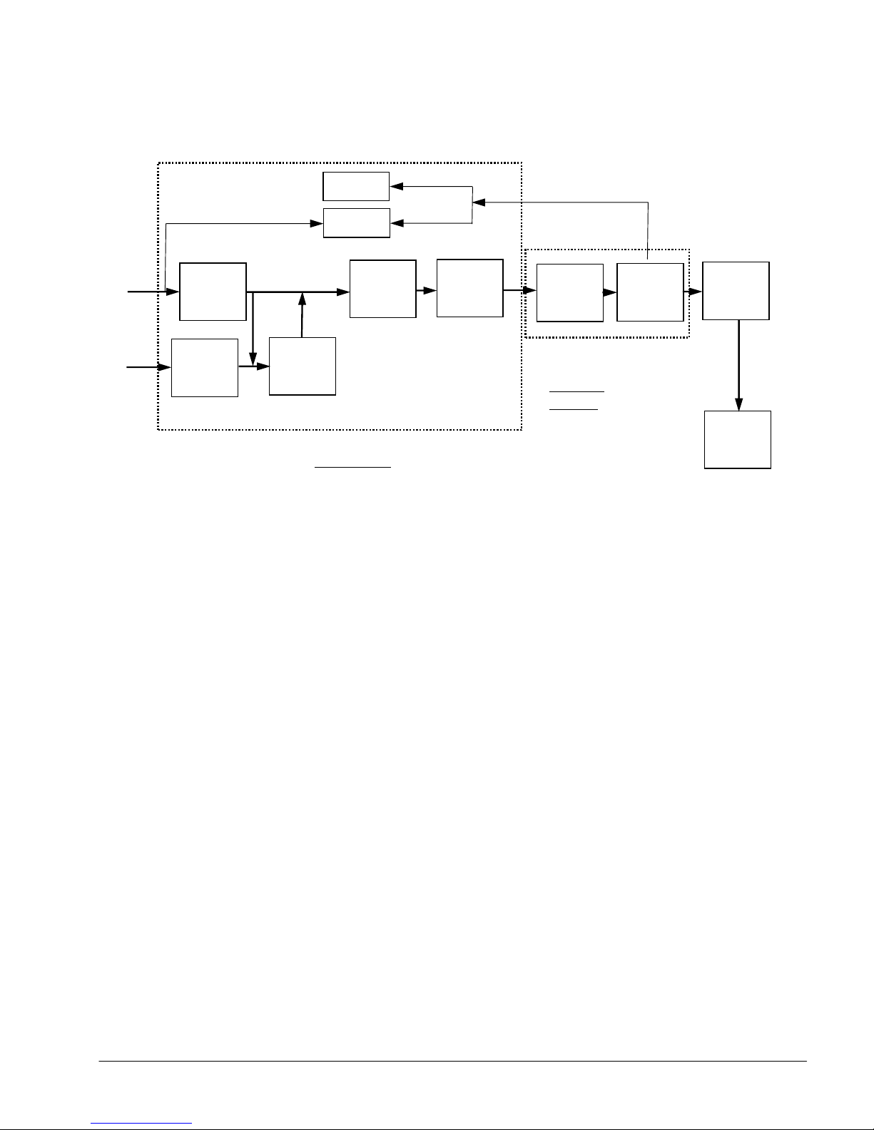
9.2 Circuit Description
Patient
Ventilation
Patient
Patient Patient
Patient
circuit
circuitcircuit
circuit
Venturi
Intake
Flow
Sensor
Pressure
Pressurized
O2
Ambient
Flow
control
Filter
When a gas source (medical oxygen) is supplied to the e700 ventilator via the
gas input connection, the gas will flow into the Flow control valve which is
used to control both the flow and rate of ventilation. The output of this valve is
connected to a selector switch which is used to direct the flow path either
directly to the ventilator output (if 100% oxygen ventilation is required) or
through a Venturi system used to entrain air to provide an oxygen
concentration of 60%.
Sensors
Pressure/
Rate
Control
Ventilator
Ventilator
VentilatorVentilator
Safety
valve
valve
Sensor
Adapter
Optional
HME
Filter
e700 User Manual
(15PL1009 - Rev.10 Dec 21, 2016) English version
50
50
5050
Page 52

9.3 Battery & Power Supply
Max. Charging
Meet requirements of
AC/DC power
DC Output Cable
AC Power Cord
Meet requirements of IEC60601
-
Battery Pack
Battery Cell Type Rechargeable Lithium Ion Cell
Type 4ICR19/65-3
Nominal Capacity 7500 mAh, Min 111Wh
Nominal Voltage 14.8V
Current
Max. Charging
Voltage
3750 mA
16.8V ± 0.1V
Dimension 144 x 62 x 42
Weight 642 g
Test specification
IEC62133:2002
Note: The behaviour of the ventilator will not be affected while the battery is
charging.
AC/DC Power Supply
supply
Nominal Input
Voltage
Model PMP90-13-2 O1CV0105
110/ 220V
Nominal Frequency 50/ 60 Hz
Input Current 1.2 A for 115 V, 0.06 A for 230 V
Output Voltage 19V DC
Output Current 4.74 A Maximum
DC Output Plug 2.5 x 5.5 x 11mm
Length
Length
Weight 642 g
EMC performance Meet requirements of IEC60601-1-2
Safety Standards
Note: Upon disconnecting AC Power supply, Ventilator will automatically
switch to Battery operation without affecting ventilator behaviour.
6’
6’
1:2005
e700 User Manual
(15PL1009 - Rev.10 Dec 21, 2016) English version
51
51
5151
Page 53
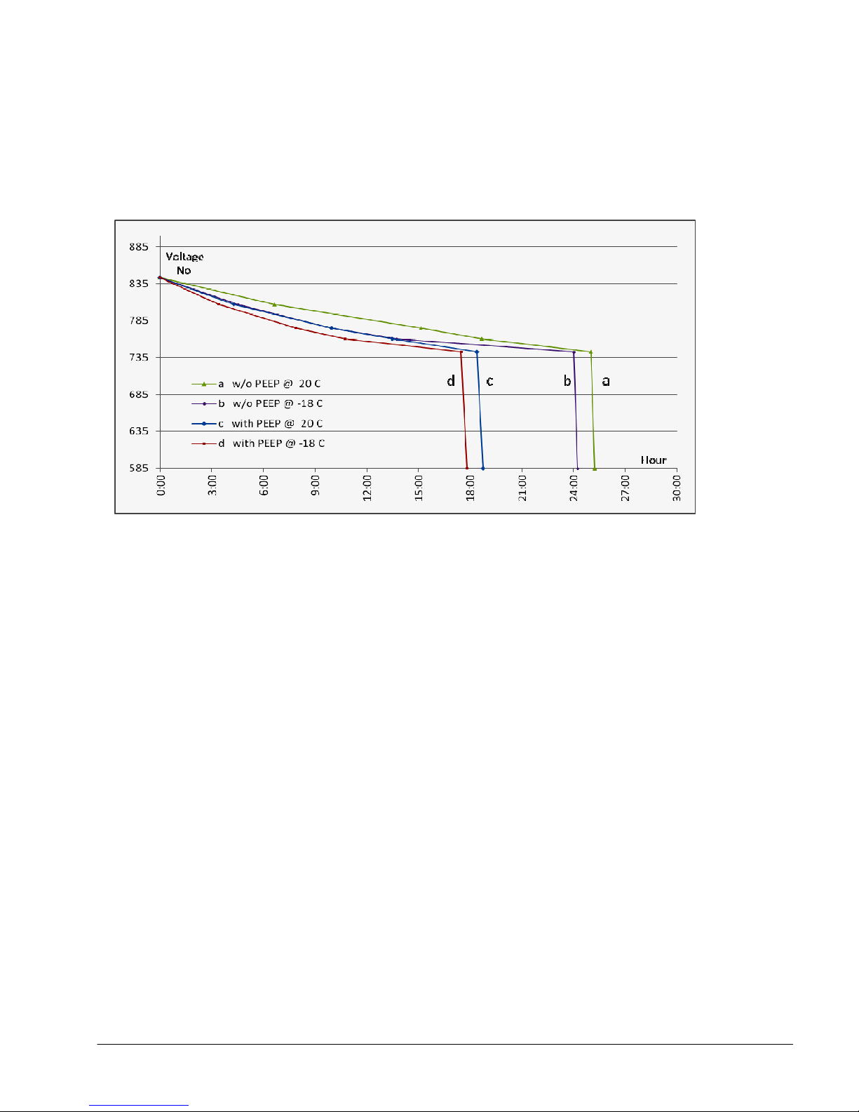
Battery Discharge time
9.4 Battery Operating Time
Battery operation time ranges from 24 hours in Normal operation and
temperature conditions to 15 hours in extreme operation and temperature.
e700 User Manual
(15PL1009 - Rev.10 Dec 21, 2016) English version
52
52
5252
Page 54

Emission test
Emission testEmission test
Emission test
Compliance
ComplianceCompliance
Compliance
Electromagnetic environment
Electromagnetic environment Electromagnetic environment
Electromagnetic environment
----
The
OOOO
----
Two
TwoTwo
Two
e700
e700e700
e700
uses RF energy only for
RF emissions
The
OOOO
----
Two
TwoTwo
Two
e700
e700e700
e700
external power supply
Harmonic
Electrostatic discharge
± 6 kV contact
± 8
kV contact
Electrical fast transient/
± 2 kV for power
± 2 kV for power
Surge IEC61000
-4-5
± 1 kV line to line;
± 1 kV line to line;
Power frequency (50/60
3 A/m
30 A/m
9.5 Electromagnetic Compatibility
OOOO----Two
Two e70
TwoTwo
requirements.
Electromagnetic Emissions
OOOO----Two
Two e700
TwoTwo
below. The user of OOOO----Two
environments outside those specified:
e700
0 has been tested and complies with IEC 60601-1-2:2007
e70e70
0 0
e700 is intended for use in the electromagnetic environment specified
e700 e700
Two e700
TwoTwo
e700 should assure that it is not used in
e700 e700
guidance
guidance
guidanceguidance
RF emissions
Group 1
CISPR 11
CISPR 11
emissions
Class B
Class A
IEC61000-3-2
Voltage
fluctuations/
flicker emissions
complies
IEC61000-3-3
Electromagnetic Immunity
Immunity test IEC60601 required
(ESD) IEC61000-4-2
its internal function. Therefore, its RF
emissions are very low and are not likely
to cause any interference with nearby
electronic equipment
is suitable for use in all establishments
including domestic establishments and
those directly connected to the public
low-voltage power supply network that
supply buildings used for domestic
purposes.
Actual compliance
test level
± 8 kV air
± 15 kV air
level
burst
IEC61000-4-4
Voltage dips, short
interruptions and voltage
variations on power supply
input lines
IEC61000-4-11
Hz) magnetic field
IEC61000-4-8
supply lines
± 1 kV for
input/output lines
± 2 kV line to earth
<5%UT for 0.5 cycle
40%UT for 5 cycle
70%UT for 25 cycle
<5%UT for 5 s
e700 User Manual
(15PL1009 - Rev.10 Dec 21, 2016) English version
supply lines
± 1 kV for
input/output lines
± 2 kV line to earth
<5%UT for 0.5 cycle
40%UT for 5 cycle
70%UT for 25 cycle
<5%UT for 5 s
53
53
5353
Page 55

Conducted RF
3Vrms: 50kHz to 80
3 Vrms
10Vrms: 150kHz to 80
10 Vrms
Radiated RF
10 V/m @
3
0 V/m
150kHz
to 800
150kHz to 800
80 MHz to
800 MHz to
0.01
0.12
0.12
0.12
0.23
0.1 0.4 0.4 0.4 0.7
10 3.8 3.8 3.8 7.3
IEC61000-4-6
MHz outside ISM
bands
MHz in ISM bands
IEC61000-4-3
OOOO----Two
Two e700
e700 is intended for use in the electromagnetic environment in which
TwoTwo
e700 e700
radiated RF disturbances are controlled. The user can help prevent
electromagnetic interference by maintaining a minimum distance between
portable and mobile RF communications equipment (transmitters) and the OOOO---Two
Two e700
e700 as recommended below, according to the maximum output power
TwoTwo
e700 e700
of the communications equipment:
Rated
maximum
output power
of transmitter
W
1 1.16 1.2 1.2 2.3
100 12 12 12 23
MHz outside
ISM bands d =
√
3.5/3 *
P
80 MHz to 2.5 GHz
Separation distance (m)
Separation distance (m)
Separation distance (m)Separation distance (m)
MHz in ISM
bands d = 1.2
√
P
800 MHz
d = 1.2
2.5 GHz
√
P
d = 2.3
√
P
e700 User Manual
(15PL1009 - Rev.10 Dec 21, 2016) English version
54
54
5454
Page 56

9.6 Oxygen Consumption
For a “D” size cylinder (capacity of 425 liters), pressurized to 2015 PSI and
with the e700 set to the Adult default setting (Vt= 500ml, Rate= 10BPM, 100%
Oxygen) the pneumatic operating time is 85 minutes without PEEP (0.2 min/L)
and is 39 minutes with maximum PEEP (0.089 min/L).
Duration of consumption of a cylinder in minutes is calculated approximately
by dividing the liter content by the minute volume with or without PEEP.
e700 User Manual
(15PL1009 - Rev.10 Dec 21, 2016) English version
55
55
5555
Page 57
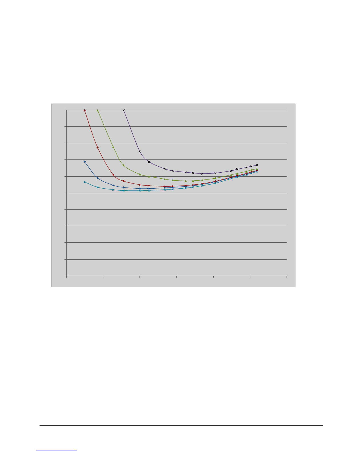
0 cmH
2O
60 cmH2O
30 cmH2O
5 cmH2O
9.7 Oxygen Concentration delivered against different back
pressures
100
90
15 cmH2O
80
70
60
50
40
30
20
10
0
0 20 40 60 80 100 12 0
Flow Rate
OOOO
Concentration
Concentration
Concentration Concentration
2222
%%%%
Flow Rate
Flow RateFlow Rate
L/min
e700 User Manual
(15PL1009 - Rev.10 Dec 21, 2016) English version
56
56
5656
Page 58
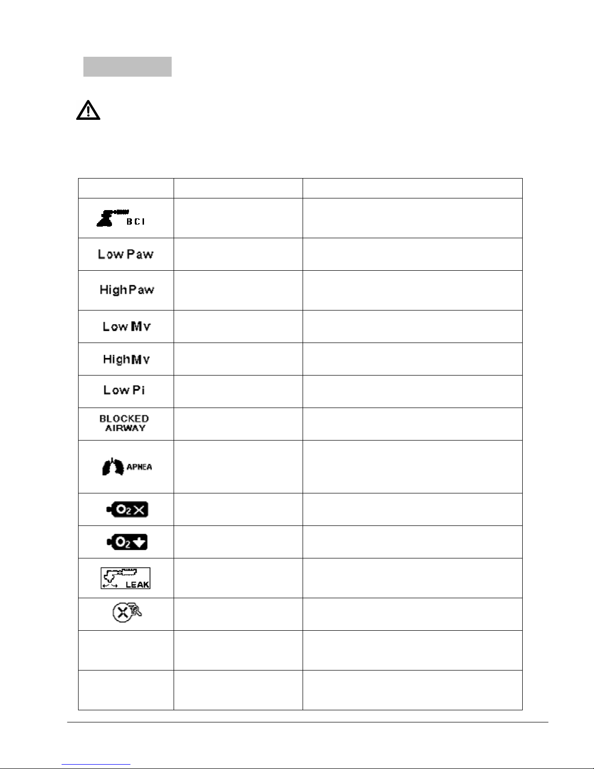
Chapter 10 Trouble shooting
Check patient, ventilation circuit,
Apnea, spontaneous
Leakage, measured
Trouble shooting
Trouble shootingTrouble shooting
Warning
Warning
WarningWarning
Please contact manufacturer if a problem cannot be rectified. For the safety of
the patient and the Health care providers DO NOT continue using the
ventilator.
Message/fault
Message/fault cause
Message/faultMessage/fault
Leaking mask, ETT,
disconnected patient
circuit
Low Airway Pressure
cause Remedy
causecause
Remedy
RemedyRemedy
Make sure mask fits / all patient circuit
parts are properly connected./change
patient circuit
Replace hose, check tube position,
check ventilation settings and correct
High Airway Pressure
Low minute Volume Check patient / reset parameters.
High Minute Volume Check patient / reset parameters.
Low inhalation
pressure
check tube position, adjust Pmax
alarm value
Check mask, patient Integrity
Obstructed Airway Check airway, patient
breathing failed or
disconnection, faulty
sensor
No Oxygen ≤ 20 PSI
Low Oxygen(40-21
PSI)
expiratory volume is
Switch to Assist Control ventilation,
ensure connections tight, Replace
patient circuit
Change Oxygen cylinder
Change Oxygen cylinder
Check leakage in breathing system.
40% lower than set.
Invalid setting
Battery
discharges
quickly
e700 cannot
be switched on
No proper
charging/Faulty
battery
Battery empty/no
power supply
connected/defective
Resolve parameters conflict by
resetting out of range parameters
Charge Battery as per
instructions/Replace battery
Change Battery/connect power
supply/ send to O-Two for repair or
service
e700 User Manual
(15PL1009 - Rev.10 Dec 21, 2016) English version
57
57
5757
Page 59

A/C V
Assist Control Ventilation
BiLVL
Bi
phasic Positive Airway
pressure
CPR
Cardio Pulmonary Resuscitation
Rate
Ventilation
rate
(number
of breaths per minute)
Termination
% of Maximum flow value
I:E Ratio of inspiration time to expiration time
Mve
Exhaled
Minute Volume
O2 (%) Percentage of Oxygen inspired
Paw (peak)
Peak airway pressure
PCV
Pressure cont
r
ol Ventilation
PEEP
Positive End Expiratory Pressure
Pi Inhalation Pressure
Pmax
Maximum ai
rway pressure
P min
Minimum airway pressure
SIMV
Synchronized Intermittent Mandatory Ventilation
APNEA
Te Expiratory time
Ti Inspiration time
Trig.
Triggering flow
rate
Vte
Exhaled
Tidal volume
Vt Tidal volume
Chapter 11 Abbreviations
Abbreviations and
AbbreviationsAbbreviations
and Acronyms
andand
Acronyms
AcronymsAcronyms
Term
Term Explanation
TermTerm
BCI Breathing Circuit Integrity (Patient circuit disconnect)
CPAP Continuous Positive Airway Pressure
LED Light Emitting Diode
Mv Minute volume
Paw (AV) Average airway pressure
Explanation
ExplanationExplanation
PSV Pressure Support Ventilation
T
TFT Thin Film Transistor
Apnea Alarm time
e700 User Manual
(15PL1009 - Rev.10 Dec 21, 2016) English version
58
58
5858
Page 60
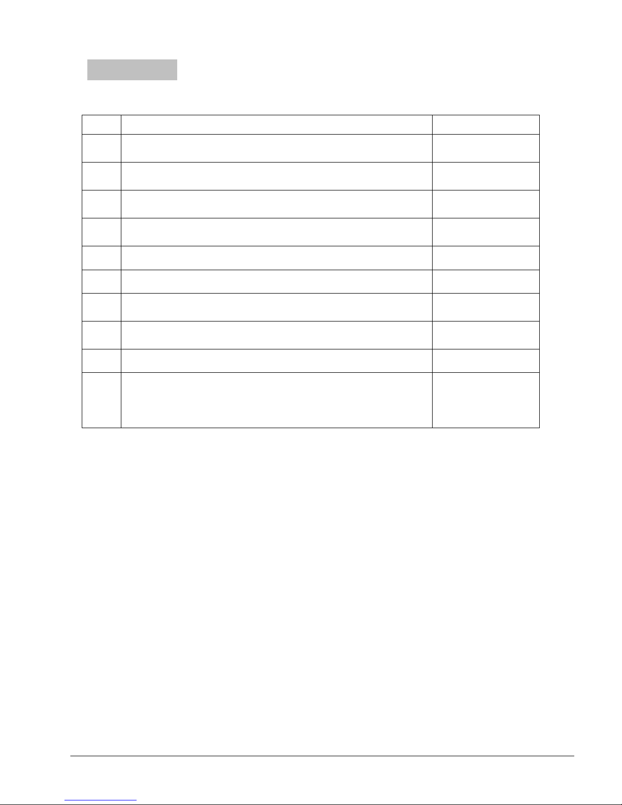
Chapter 12 Accessories
O-Two Single
-
Use Electronic
Transport Ventilator
PVC 6’
(1.83 m) input pressure hose
– 9/16” DISS
nut
Power supply Cord (Canada and the US)
*
“FIXED MOUNT”
Mounting Bracket
for mobile
Bacterial and Viral Filter case of 40 / Bacterial and
02RT7500/U
Item
Item
ItemItem
Accessories
AccessoriesAccessories
Part
Part Order number
PartPart
Order number
Order numberOrder number
1.
circuit 6’ (1.83 m)patient circuit
2.
fitting
Intake filter-case of 10
3.
4.
01CV8030
01FV4302 *
01CV8040-cs
01CV0106
5. Battery Pack 01CV9100
6. e Ventilator External Power Supply 01CV0105
“SMART MOUNT” Mounting Bracket for Road
7.
8.
ambulance
setting
01EV7035
01EV7036
9. 1L Test lung 01TA8152
10.
Viral Filter unit.
Dead space and Resistance (@ -30 Lpm) of Viral
and Bacterial filter: 26 ml & 0.7 cmH2O
Note
Note
NoteNote
****When ordering the ventilator please specify the input hose and power cable
connectors.
e700 User Manual
(15PL1009 - Rev.10 Dec 21, 2016) English version
59
59
5959
Page 61

Chapter 13 WARRANTY
WARRANTY
WARRANTYWARRANTY
O-Two Warrants the e700 ventilator, when used in accordance with the
instructions contained within this Manual, for a period of two years from the
date of purchase except for the following cases:
1. Using unspecified parts/accessories
2. An attempt to service by unqualified persons/entities
3. Negligence
4. Normal wear and tear (filters, batteries, patient circuits)
Warning
Warning
WarningWarning
It is recommended that the routine preventive maintenance shall be
carried out at least every 6 months from date of purchase. Repair and
general overhaul of the ventilator must be carried out by trained service
personnel. Evaluation of performance against manufacturer’s
specifications may be undertaken by suitably qualified personnel to
determine if the ventilator is functioning within specification. Any
ventilators deemed to be out of specification must be returned to OTwo Medical Technologies Inc. (or one of its approved Service Centers)
for service and/or repair.
We recommend that a service contract be obtained with O-Two Medical
Technologies Inc. (or one of its approved Service Centers) and that all
repairs also be carried out by them.
Only authentic O-Two Medical Technologies Inc. spare parts may be
used for maintenance.
Liability for proper function or damage
Liability for proper function or damage
Liability for proper function or damage Liability for proper function or damage
The liability for the proper function of the apparatus is irrevocably transferred
to the owner or operator to the extent that the apparatus is serviced or
repaired by personnel not employed or authorized by O-Two Medical
Technologies Inc. or if the apparatus is used in a manner not conforming to its
intended use.
O-Two Medical Technologies Inc. cannot be held responsible for damage
caused by non-compliance with the recommendations given above.
The warranty and liability provisions of the terms of sale and delivery of O-Two
Medical Technologies Inc. are likewise not modified by the recommendations
given above.
e700 User Manual
(15PL1009 - Rev.10 Dec 21, 2016) English version
60
60
6060
Page 62

Marcel Houben
4030 LIEGE Belgique
eeee700
700
700700
SN ____________
SN ____________
SN ____________SN ____________
OOOO----Two
Two Medical Technologies Inc.
Medical Technologies Inc.
TwoTwo
Medical Technologies Inc.Medical Technologies Inc.
45A, Armthorpe Road, Brampton,
45A, Armthorpe Road, Brampton,
45A, Armthorpe Road, Brampton, 45A, Armthorpe Road, Brampton,
Ontario, Canada, L6T 5M4
Ontario, Canada, L6T 5M4
Ontario, Canada, L6T 5M4Ontario, Canada, L6T 5M4
Offi
Office: +1 905 792 OTWO (6896)
ce: +1 905 792 OTWO (6896)
OffiOffi
ce: +1 905 792 OTWO (6896) ce: +1 905 792 OTWO (6896)
N.A. Toll Free: +1 800 387 3405
N.A. Toll Free: +1 800 387 3405
N.A. Toll Free: +1 800 387 3405N.A. Toll Free: +1 800 387 3405
Fax: +1 905 799 1339
Fax: +1 905 799 1339
Fax: +1 905 799 1339Fax: +1 905 799 1339
Email: [email protected]
Email: [email protected]
Email: [email protected]Email: [email protected]
Web: otwo.com
Web: otwo.com
Web: otwo.comWeb: otwo.com
Rue Vinave, 32
e700 User Manual
(15PL1009 - Rev.10 Dec 21, 2016) English version
61
61
6161
 Loading...