


Otometrics Madsen A450
User Guide
Doc. No.7-50-1830-EN/02
Part No.7-50-18300-EN

Copyrightnotice
The manufacturer authorizes GN Otometrics A/S to publish manuals approved and released by the manufacturer.
© 2017,2017GNOtometricsA/S.All rights reserved. ® Otometrics, the OtometricsIcon, AURICAL, MADSEN, ICSand HORTMANN
are registered trademarks of GNOtometricsA/S in the U.S.A.and/or other countries.
Version release date
2017-03-20 (153952)
Technical support
Please contact your supplier.
Otometrics - Otometrics Madsen A450
2

Table of Contents
1 Device description
5
2 Intended use
5
3 Unpacking
6
4 Installation
6
5 Connecting accessories to Otometrics Madsen A450
7
6 Powering the device
8
7 Connecting Otometrics Madsen A450 to OTOsuite
9
8 Control panels and On-screen controls
10
9 Toolbar icons in the Audiometry Module
15
10 PC keyboard controls
16
11 Proper transducer placement
16
12 Performing tone audiometry
17
13 Performing speech audiometry
19
14 Service, cleaning and calibration
21
15 Other references
22
16 Technical specifications
22
17 Definition of symbols
34
18 Warning notes
34
19 Manufacturer
37
3
User Guide
Otometrics - Otometrics Madsen A450

Otometrics - Otometrics Madsen A450
4

1 Device description
Otometrics Madsen A450
Otometrics Madsen A450 is a PC-controlled audiometer for testing a person's hearing.The audiometer is operated from the OTOsuite Audiometry
Module PC software.
• With Otometrics Madsen A450 you can perform all standard audiometric tests, tone and speech audiometry and special tests. Technical
Specifications,
2 Intended use
Otometrics Madsen A450 with the Audiometry module
Users: audiologists, ENTs, hearing instrument dispensers and other health care professionals in testing the hearing of their
patients.
Use: diagnostic and clinical audiometric testing.
2.1 Typographical conventions
The use of Warning, Caution and Note
To draw your attention to information regarding safe and appropriate use of the device or software, the manual uses precautionary statements as follows:
Warning• Indicates that there is a risk of death or serious injury to the user or patient.
Caution• Indicates that there is a risk of injury to the user or patient or risk of damage to data or the device.
Note• Indicates that you should take special notice.
Otometrics - Otometrics Madsen A450
5
1 Device description

3 Unpacking
1. Unpack the device carefully.
When you unpack the device and accessories, it is a good idea to keep the packing material in which they were
delivered. If you need to send the device in for service, the original packing material will protect against damage during transport, etc.
2. Visually inspect the equipment for possible damage.
If damage has occurred, do not put the device into operation. Contact your local distributor for assistance.
3. Check with the packing list to make sure that you have received all necessary parts and accessories. If your package is
incomplete, contact your local distributor.
4. Check the Test Report (Calibration Certificate), make sure that the transducers (headphones and bone oscillator) are
the correct ones, and that they comply with the ordered calibration standards.
4 Installation
Install OTOsuite on the PC before you connect to Otometrics Madsen A450 from the PC.
For instructions on installing OTOsuite, see the OTOsuiteInstallation Manual, which you can find on the OTOsuite installation medium (disk or memory stick).
Otometrics Madsen A450 is fully assembled on delivery, and you simply have to connect cables.
Caution• To connect Otometrics Madsen A450 to the PC, use the supplied USB cable. The cable length
must not exceed 3 m (approx. 10 feet).
Desktop or wall-mount installation
You can place Otometrics Madsen A450 on the desktop or mount it on the wall.
6 Otometrics - Otometrics Madsen A450
3 Unpacking
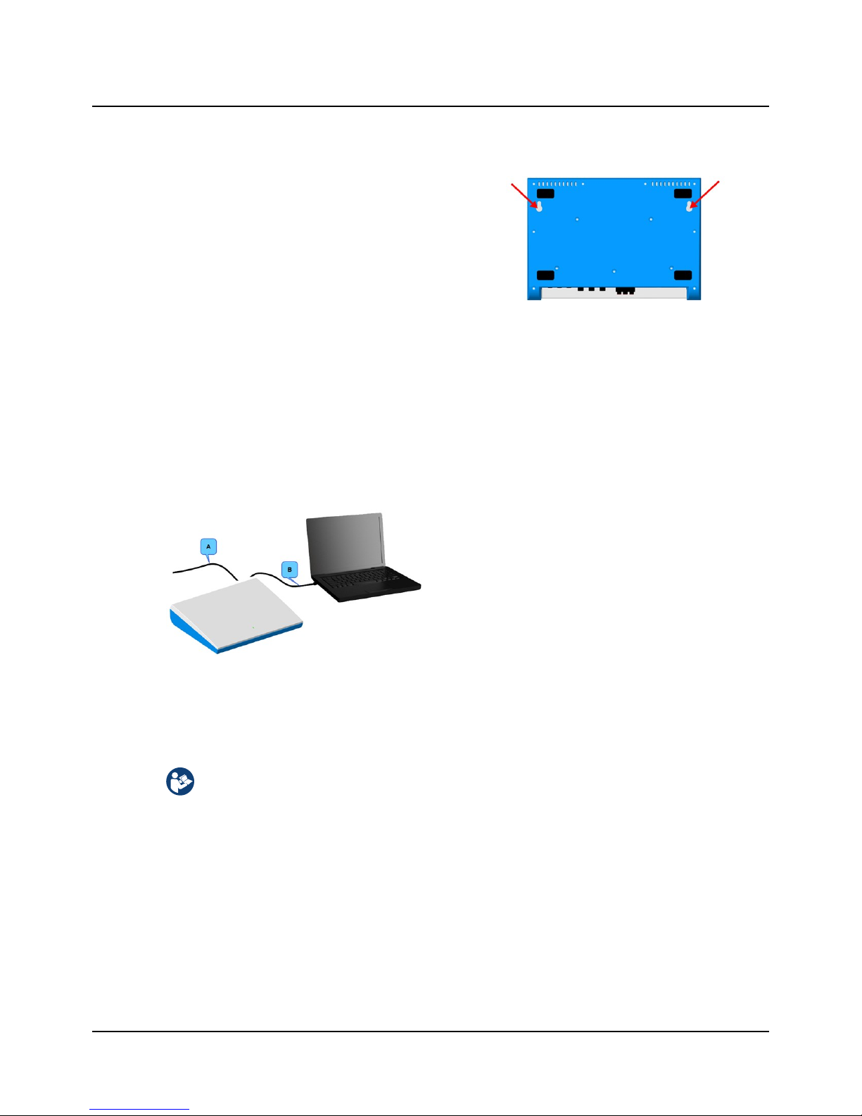
Wall-mount installation
It is recommended that you connect the external power supply and the accessories before you mount Otometrics Madsen
A450 on the wall.
1. Select two suitably sized screws that will pass through the
wall-mount holes on the back of the device:
Max. screw diameter 4.3 mm (0.15 in).
Max. screw head diameter: 9 mm (0.35 in).
2. The distance between the two wall-mount holes on the
back of the device is 24 cm (9.4 inches), measured from
the center of each hole.
3. Mark up the two holes on the wall and make sure that the
device will be placed horizontally.
4. Fix the two screws in the wall.
5. Hang Otometrics Madsen A450 on the screws.
Otometrics Madsen A450 cabling
A. External power supply cable
B. USB cable between Otometrics Madsen A450 and the
PC
5 Connecting accessories to Otometrics Madsen A450
The installation must be carried out in accordance with IEC 60601-1-1 plus addendum in the form of Part 1:
General provisions -1 and UL 60601-1, CAN/CSA-C22.2 NO 601.1-90. The supplementary provisions on the reliability of electro-medical systems.
It is a general rule for all electrical equipment used in the proximity of the client that:
• The connected equipment must comply with IEC 60601-1 and/or IEC 60601-1-1
except for the PC, and equipment connected to the line in and the line out sockets of Otometrics Madsen
A450.
See also General warning notes ► 35.
For a detailed description of the connection panel, see the Otometrics Madsen A450Reference Manual.
Otometrics - Otometrics Madsen A450
7
5 Connecting accessories to Otometrics Madsen A450
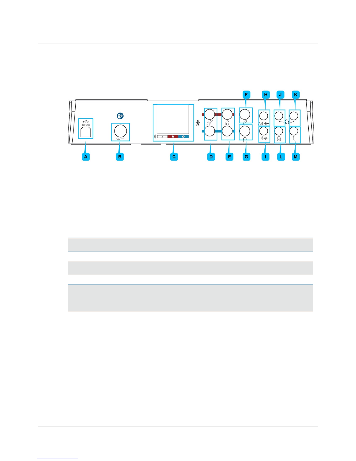
Connection panel - Otometrics Madsen A450
1. Connect the plugs to the sockets in the connection panel.
A. PC/USB connection
B. External power supply
C. Sound field speakers (power output)
D. Insert earphones
E. Headphones - air conduction
F. Patient Responder
G. Bone oscillator
H. Speaker, Analog (line output)
I. Line-in
J. Operator monitor headset - headphones
K. Operator monitor headset - boom microphone
L. Counseling and Simulations headphones
M. Talk-back microphone
Note• Blue corresponds to Left and red corresponds to Right.
Warning• Use only the power supply provided by Otometrics.
Caution• When you connect other electrical equipment to Otometrics Madsen A450, remember that equipment that
does not comply with the same safety standards as Otometrics Madsen A450 can lead to a general reduction in the
system's safety level.
Connecting an external speaker
External speakers can be connected to Otometrics Madsen A450 via powered output terminals or line-out terminals. In
both cases you should contact your service department for installation and calibration. See also Calibration ► 21.
6 Powering the device
Otometrics Madsen A450 is powered through an external power supply connected directly to the mains outlet.
8 Otometrics - Otometrics Madsen A450
6 Powering the device
Warning• Otometrics Madsen A450 is not provided with a mains switch.
To connect Otometrics Madsen A450 to the mains supply, plug the mains plug into the wall mains outlet.
To disconnect Otometrics Madsen A450 from the mains supply, pull the mains plug out of the wall mains outlet. Do
not position the unit so that it is difficult to pull the mains plug out of the wall mains.
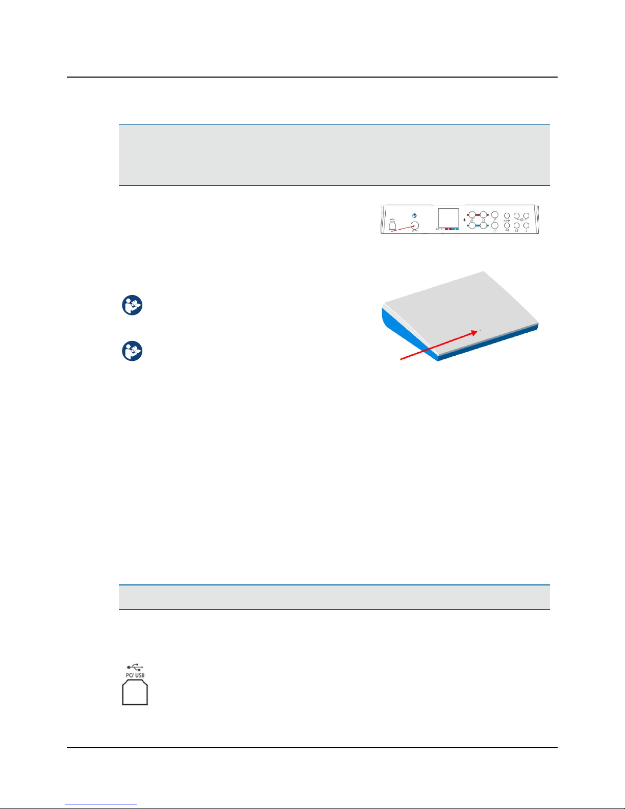
1. Plug the external power supply into the Power socket in the connection panel.
2. Plug the mains plug of the external power supply into an AC mains
outlet with a three-wire protective ground.
Switching on Otometrics Madsen A450
Use only the power supply specified in Technical Specifications in the Otometrics Madsen A450Reference
Manual.
1. Connect the mains plug of the external power supply directly to an AC mains outlet with a threewire protective ground.
2. Switch on the mains supply.
3. The On/Off indicator on Otometrics Madsen A450
lights green.
Switching off Otometrics Madsen A450
1. To completely switch off Otometrics Madsen A450, disconnect the power supply from the mains outlet.
7 Connecting Otometrics Madsen A450 to OTOsuite
To connect Otometrics Madsen A450 to the PC, you must install OTOsuite on the PC.
For instructions on installing OTOsuite, see the OTOsuiteInstallation Manual, which you can find on the OTOsuite installation medium (disk or memory stick).
Caution• Use only the USB cable supplied with Otometrics Madsen A450.
1. Switch on the device.
1. Launch OTOsuite.
2. Connect the USB cable from the USB socket on the back of the device to a USB socket on the PC. The
OTOsuite software automatically detects the device.
Otometrics - Otometrics Madsen A450
9
7 Connecting Otometrics Madsen A450 to OTOsuite

8 Control panels and On-screen controls
Control panels
Tone testing Speech testing
In the control panel you can quickly select test ear, transducer, masking, and test type.
Click on the buttons to toggle the selection or right-click on a
button to select a combination of functions.
Your selections are shown in the Stimulus bar and as symbols
in the audiogram.
You can control the monitor level, activate the Talk Forward
dialog, and use the Test Selector to quick select the relevant
user test.
• Right-click on the buttons in the control panel to view
the right-click menu. Click to enable or disable selections
of your choice.
• Right-click on the blue masking link area in the control
panel to view the Masking Options right-click menu.
Click to enable or disable selections of your choice.
Tone testing
Test ear selection
• Right
• Both
• Left
Transducer selection
• Air conduction Phones (standard headphones), optional
10 Otometrics - Otometrics Madsen A450
8 Control panels and On-screen controls
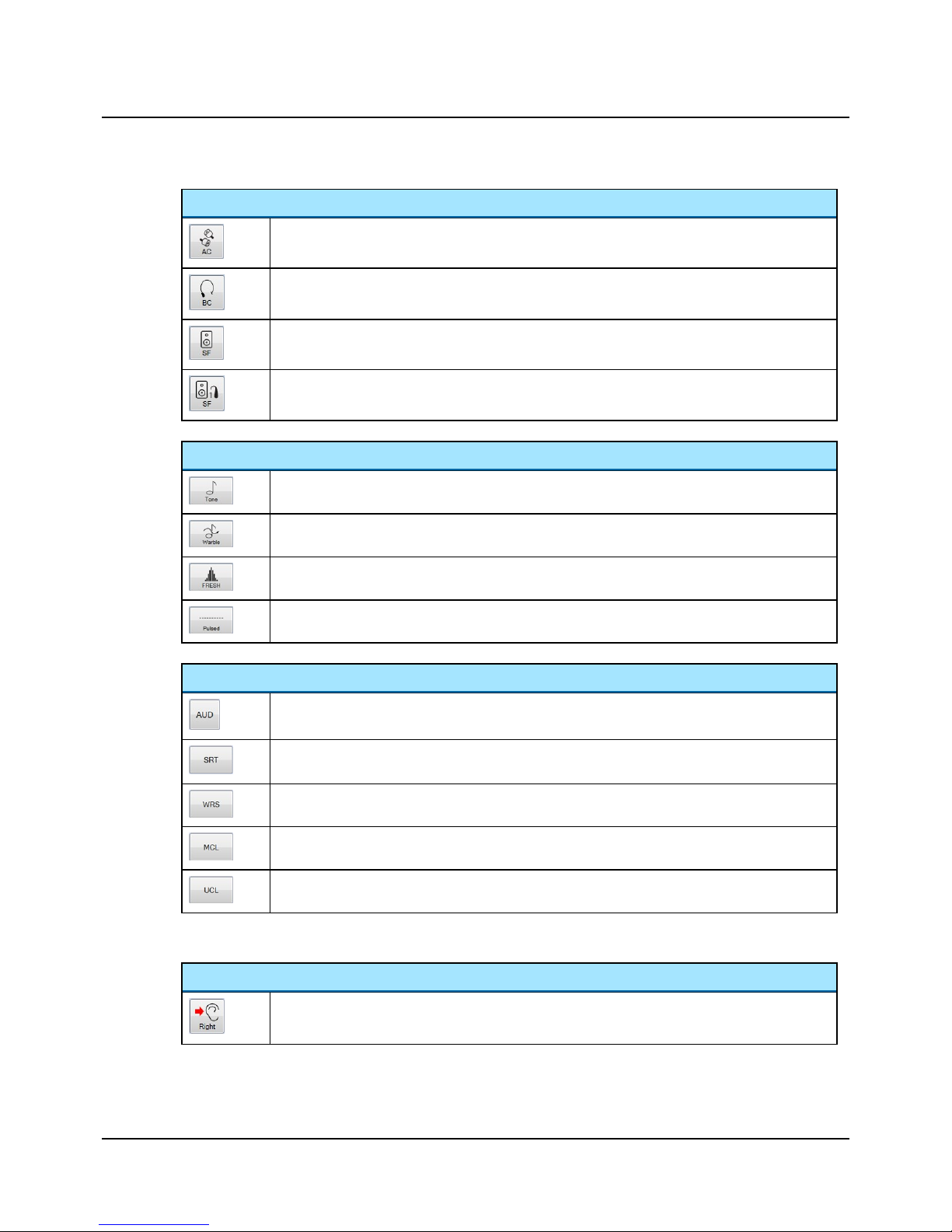
Transducer selection
• Air conduction Insert (earphones), optional
• Bone conduction Bone (oscillator)
• SF Unaided (Sound Field speaker, unaided), optional
• SF Aided 1 and SF Aided 2 (Sound field speaker - Aided 1 and 2), optional
Stimulus type selection
• Tone
• Warble
• FRESH noise
• Pulsed
Test type selection
• AUD (audiogram threshold curve)
• SRT (Speech Recognition Threshold)
• WRS (Word Recognition Score)
• MCL (Most Comfortable Loudness level)
• UCL (Uncomfortable Loudness level)
Speech testing
Test ear selection
• Right
Otometrics - Otometrics Madsen A450
11
8 Control panels and On-screen controls

Test ear selection
• Both
• Left
Transducer selection
• Air conduction Phones (standard headphones), optional
• Air conduction Insert (earphones), optional
• Bone conduction Bone (oscillator)
• SF Unaided (Sound Field speaker, unaided), optional
• SF Aided 1 and SF Aided 2 (Sound field speaker - Aided 1 and 2), optional
Stimulus type selection
• Microphone for presenting live speech stimulus
• Recorded stimulus
Talk Forward
Click to open the Talk Forward dialog. See the Otometrics Madsen A450Reference Manual.
Enables communicating with the patient in the sound booth. This will display the Talk Forward dialog
box, where you can control the talk forward microphone sensitivity and the output level (in dB HL) to
the patient.
Monitor and Level
Click to open the Monitor and Level dialog. See the Otometrics Madsen A450Reference Manual.
12 Otometrics - Otometrics Madsen A450
8 Control panels and On-screen controls

Test Selector
Click to open the Test Selector dialog. See the Otometrics Madsen A450Reference Manual.
The Control Panel right-click menu
Right-click on the buttons in the control panel to view the right-click menu. Click to enable or disable selections of your
choice.
Stimulus Ear Selection
Left,Right,Both
Transducer Selection Insert,Phones,Bone,SF Unaided,SF Aided 1,SF Aided 2
Stimulus Selection Tone
• Tone
• Warble
• FRESH
• Pulsedstimulus
• Stim. Lock
• Tracking
• 1 dB step
• 5 dB step
Speech
• Mic
• Recorded (Source A)
• Recorded (Source B)
• Int. CD (internal CD ROM built into the PC) (Speech)
• File (stored on hard drive) (Speech)
• Line In (external medium connected to the PC) (Speech)
• Stim. Lock (presents stimulus and masker simultaneously)
• Tracking (increases stimulus and masker intensity by the same number of dB)
• 1 dB Step
• 5 dB Step
Otometrics - Otometrics Madsen A450
13
8 Control panels and On-screen controls

Curve Selection • AUD (audiogram threshold curve) (Tone)
• MCL
• UCL
• SDT (Speech Detection Threshold) (Speech)
• SRT (Speech Recognition Threshold) (Speech)
• WRS (Word Recognition Score) (Speech)
• SNR (Signal to Noise Ratio) (Speech)
Masking Transducer
Selection
• Insert
• Phone
• Bone (Speech)
• SF
Masking Options • Contralateral
• Ipsilateral
• NBN (Tone)
• WN (Tone)
• Stimulus 2 (Stenger)
• SWN (Speech)
• Mic (Speech)
• Recorded (Source A) (Speech)
• Recorded (Source B) (Speech)
The stimulus bar
Test controls provide a means of operating the audiometer if you use the mouse and on-screen options to perform tests.
• To enable test controls, select Tools> Options> Audiometry> General> On-screen controls> Show> On.
Button Description
Present
Click to present the stimulus.
Store
Click to store the data point or row.
Mask
Click to enable or disable masking.
Silence Mode
Silence Mode allows you to control tone levels and presentation by hovering the mouse cursor over the respective onscreen controls. This is particularly useful when the operator of the audiometer and the person being tested are in the
same room.
• To enable silence mode, select Tools> Options> Audiometry> General> On-screen controls> Silence Mode> On.
• To change the level and frequency by more than one click at a time, use the mouse scroll wheel.
14 Otometrics - Otometrics Madsen A450
8 Control panels and On-screen controls

9 Toolbar icons in the Audiometry Module
The icons available in the toolbar depend on the test function that you have selected.
Functions not available in the toolbar can be accessed from the View menu or from Tools> Options dialog.
Audiometry icons
Tone audiometry Speech audiometry
Toolbar selections
Menu item Icon Description
View> Combined
Audiogram
Click to toggle between viewing both ears in a single audiogram (combined audiogram) or both a left and a right audiogram on your screen.
Combined View
• Click to view both ears in a single audiogram.
Split View
• Click to view separate audiograms for each ear.
Scoring and Playing Click to open the Scoring and Playing dialog.
Menu selections
Menu item Icon Description
View> Select Orientation
Click to select the perspective of the patient's ears as presented on
the screen for graph and table views.
You can also select the location of the stimulus control.
View> Manual entry
Click to create an audiogram manually.
Otometrics - Otometrics Madsen A450
15
9 Toolbar icons in the Audiometry Module

10 PC keyboard controls
You can open a separate PDF-file to have a proper view of the keyboard shortcuts.
After you install OTOsuite, you can find OTOsuite manuals and related documentation on your PC. In the Start menu, open , which contains an overview
with links to all manuals.
Note• The actual position of the keys may depend on your keyboard
type.
11 Proper transducer placement
Headphones
1. Loosen the headband and place both the left and right side of the headphones simultaneously.
Note• If the headphones are not placed properly, there is risk of causing the ear canal to collapse which will result in
elevated thresholds.
2. Aim the center of the headphones towards the patient's ear canals and gently place them against the ears.
3. Tighten the headband while holding the headphones in place with your thumbs.
4. Examine the placement of the headphones to make sure they are level, and properly positioned.
Insert Earphones
Young children tolerate insert earphones better than headphones.
1. Select the largest foam eartip that will fit into the patient's ear.
If the eartip is too small the sound will leak out and the dB level will not be accurate at the eardrum.
Insert earphones have greater attenuation between ears especially at the low frequencies; this reduces the need for
masking.
2. It is best to clip the insert earphone transducers behind the child or on the back of their clothing and then fit the
foam eartip into the child's ears.
Bone Oscillator
Note• For unmasked bone thresholds, you can store binaural data:
- Select Both in the Ear Selection part of the control panel.
16 Otometrics - Otometrics Madsen A450
10 PC keyboard controls

Note• If there is a difference of 10dB or greater between the bone conduction threshold and the air conduction
threshold of the same ear, masking is needed. The Masking Assistant can assist you in determining which thresholds
need to be masked.
Note• If the SRT of the test ear and the SRT or PTA of the nontest ear differ by 45dB or more, masking is needed.
If the SRT of the test ear and the bone conduction PTA of the nontest ear differ by 45 dB or more, masking is needed.
Mastoid placement
1. Move any hair covering the mastoid out of the way and place the flat round part of the bone oscillator securely on the
boniest portion of the mastoid without any part of the transducer touching the external ear.
2. Make sure the bone oscillator is tight on the mastoid but still comfortable.
3. If you are going to perform masking with earphones, position the other end of the bone oscillator headband over the
patient's temple on the opposite side of the head so that the headband of the earphones and bone oscillator fit on
the patient's head.
Loudspeaker placement
The environment in which sound-field audiometry is performed may affect the sound field near the patient.
The performance of loudspeakers for Otometrics Madsen A450 was tested by Otometrics under free-field conditions in a
large anechoic chamber. Sound pressure level, frequency response and distortion were measured by a microphone placed
1 m from the front of the speaker.
When speakers are installed in other types of environment, the characteristics of the resulting sound field should evaluated by qualified personnel.
12 Performing tone audiometry
A. Menu bar
B. Audiometry toolbar
C. Stimulus bar
D. Control panel
E. Work area
F. Feature boxes
Otometrics - Otometrics Madsen A450
17
12 Performing tone audiometry

Whenever the test buttons and other functions are used, you can use the corresponding keys on the keyboard, or the onscreen controls located at the top of the screen or in the Control Panel to the left.
For detailed examples of audiometric testing, see the Otometrics Madsen A450 Reference Manual.
1. Select the Tone screen in the OTOsuite Audiometry module.
2. Prepare the patient. If you wish to instruct the patient after you have placed the transducers on the head of the
patient, you can use the Talk Forward button. You can talk to the patient to adjust the patient communication levels
when Talk Forward is active.
3. In the Control Panel, select test conditions for ear, transducer, unmasked/masked, and test type.
4. Select the test frequency with the Right/Left arrow buttons (or on keypad).
5. Select the stimulus level with the Up/Down arrow buttons (or on keypad).
6. Present the tone stimulus with the Present button or the space bar on the keypad.
7. Use the Store button (the S key on the keypad) to store the data point and proceed to the next frequency.
8. Repeat steps 4 to 7 until all the measurements you need have been completed. If needed, did you test:
– Both ears
– Air conduction
– Bone conduction
– Masking (Mask button or M on the keypad)
– Audiogram threshold (AUD), MCL and UCL
9. Save the audiogram.
Note• White noise can be selected for masking of pure tones. The white noise signal is calibrated for pure tone effect-
ive masking, i.e. the white noise sound pressure level varies with the pure tone frequency. If you wish to obtain a certain white noise level measured in dB SPL, you should use Conversion Table 2 to determine the appropriate
attenuator setting. See Technical specifications ► 22.
18 Otometrics - Otometrics Madsen A450
12 Performing tone audiometry

13 Performing speech audiometry
A. Menu bar
B. Audiometry toolbar
C. Stimulus and scoring bar
D. Control panel
E. Work area
F. Feature boxes
G. Audiogram
Whenever the test buttons and other functions are used, you can use the corresponding keys on the keyboard, or the onscreen controls located at the top of the screen or in the Control Panel to the left.
For detailed examples of audiometric testing, see the Otometrics Madsen A450 Reference Manual.
1. Select the Speech screen in the OTOsuite Audiometry module.
2. If needed, click the Scoring and Playing icon to set up word or phoneme scoring.
3. Prepare the patient. If you wish to instruct the patient after you have placed the transducers on the head of the
patient, you can use the Talk Forward button. You can talk to the patient to adjust the patient communication levels
when Talk Forward is active.
4. In the Control Panel, select test conditions for ear, transducer, unmasked/masked, and test type.
5. Select the stimulus level with the Up/Down arrow buttons (or on keypad).
6. Select speech input signals.
You can choose from either microphone input or recorded input source. Combining recorded Source A and Source B
as Input sources in the Test Options section of the Control Panel will replace the audiometer speech masking with a
recorded input.
7. Select your speech input from the right-click menu in the control panel.
– Int.CD (CD material in CD/DVD drive)
– Int.File (integrated OTOsuite Speech Material or regular sound files)
– Line In (analog input from external sound players, eg. CD, MD, MP3 or cassette recorders connected to the audi-
ometer via the Line In input).
Important• If an external playback device is used to generate speech stimuli via the line input, care must be
Otometrics - Otometrics Madsen A450
19
13 Performing speech audiometry

taken to ensure that the player has a flat frequency response in the range 125 to 6300 Hz. The maximum allowable deviation from the average response level is +/-1 dB; the average response level should be measured over the
range 250 to 4000 Hz.
The headset microphone is ready for use and does not require calibration or equalization procedures. The headset
microphone should be turned to a position just below the operator’s mouth.
If an external playback device is used to generate speech stimuli via the line input of Otometrics Madsen A450,
only a high quality CD player or similar device should be used; tape recordings may not provide a sufficient signal
to noise ratio. Preferably, the external device should deliver its output via a fixed-level line out connector. The
input gain on Otometrics Madsen A450 should be adjusted to obtain a 0 dBVU reading when the calibration signal is played by the external device.
8. You can find speech material files in the File/track/list selection drop-down list.
Caution• You should only use speech materials with a stated relationship between the level of the speech signal
and the calibration signal.
Speech materials delivered on CD or other media are normally accompanied by a description of this relationship.
You should follow the instructions supplied with the speech materials, using the VU-meter in OTOsuite for adjustment of input gain.
If you are using built-in speech materials supplied with OTOsuite, the speech levels have been adjusted according
to the original speech material instructions.
Note• Speech signals are calibrated in dB HL.
If you are using an integrated word list, the word list is shown on the screen.
9. Present the word lists with the Play button.
10. Use the Correct (+) and Incorrect (-) buttons or click directly on the key word to score.
11. Store the current data as the result, either by clicking Store in the highlighted field, or
by pressing (S) on the keyboard.
12. Repeat until all the measurements you need have been completed.
20 Otometrics - Otometrics Madsen A450
13 Performing speech audiometry

14 Service, cleaning and calibration
Warning• Under no circumstances disassemble Otometrics Madsen A450. Contact your supplier. Parts inside Oto-
metrics Madsen A450 must only be checked or serviced by authorized personnel.
14.1 Cleaning
The device
• Remove dust using a soft brush.
• Use a soft, slightly damp cloth with a small amount of mild detergent or approved non-caustic medical grade disinfectant wipes to clean the unit according to local infection control regulations.
Keep the unit away from liquids. Do not allow moisture inside the unit. Moisture inside the unit can damage the instrument and it may result in a risk of electrical shock to the user or patient.
Accessories
These parts are in constant contact with your patients and should therefore be kept clean.
• Headphones
Use a non-alcohol based wipe (e.g. Audiowipe) to clean the headphones between patients.
• Eartips for Insert Earphones
The eartips are disposable and therefore should not be cleaned or re-used.
• Bone oscillator
Clean the bone oscillator between patients, e.g. with a non-alcohol based antibacterial wipe, such as Audiowipes.
Disposal
There are no special requirements for the disposal of eartips, i.e. they can be discarded according to local regulations.
14.2 Calibration
Annual calibration
The audiometer, headphones, bone oscillators, and sound field speakers must be calibrated once a year by your authorized
service department.
Caution• Note that calibration has been performed only on the transducers supplied! If you wish to use any other
transducer for testing with the device, please contact your local distributor first.
Otometrics - Otometrics Madsen A450
21
14 Service, cleaning and calibration

15 Other references
For more information, see the online Help in OTOsuite, which contains detailed reference information about Otometrics
Madsen A450 and the OTOsuite modules.
For instructions on installing OTOsuite, see the OTOsuiteInstallation Manual, which you can find on the OTOsuite installation medium (disk or memory stick).
16 Technical specifications
Type identification
Otometrics Madsen A450 is type 1081 from GNOtometricsA/S.
Channels
Two separate and identical channels.
Frequency range
Insert earphones: Standard frequencies: 125 - 8000Hz
TDH39 earphones: Standard frequencies: 125 - 8000Hz
BC: Standard frequencies: 250 - 4000Hz
SF: Standard frequencies: 125 - 8000Hz
Accuracy: <0.03%.
FRESH noise stimulus: Available in entire frequency range within the transducer specified range (for
SF 125 - 8000 Hz). Accuracy 0.3%
Narrow Band Noise masking: Available for each stimulus frequency.
Frequency resolution: 125 to 8000Hz at standard frequencies
Stimulus types
• Tone
• Warble
• Pulsed tone
• Pulsed warble
• FRESH Noise Frequency-specific hearing assessment noise.
Consists of noise bands, with frequency-specific filter width.
The FRESH noise is filtered to obtain very steep slopes outside the passband.
22 Otometrics - Otometrics Madsen A450
15 Other references

Masking types
• Narrow Band Noise
– AC and BC
– SF
Correlated
Correlated
• Speech Weighted Noise
– AC and BC
– SF
Correlated
Correlated
• White Noise (Wide band noise)
– AC and BC
– SF
Correlated
Correlated
White noise for Pure Tone masking
Conversion between displayed “effective masking level” and sound pressure level
The level of white noise used for masking of pure tones is indicated in dB of “effective masking level” in OTOsuite. This
means that the sound pressure level of the power contained in a third-octave band around the presented pure tone frequency will equal the attenuator setting, plus the RETSPL at the pure tone frequency, plus the noise correction factor
from ISO 389-4:1994, Table 1.
The following tables can be used to calculate the actual sound pressure level of the white noise signal for a given attenuator setting (Table 1), or to select the attenuator setting required to obtain a specific level in dB SPL (Table 2).
Note: As the sound pressure level of the white noise signal will be quite high even for moderate attenuator settings, a
warning sign will be displayed in OTOsuite when appropriate (for levels above 100 dB HL).
Table 1 - Offset from Effective Masking Level to Sound Pressure Level
Frequency (Hz) 125 250 500 750 1000 1500 2000 3000 4000 6000 8000 9000 10000 11200 12500
Offset(dB) N/A* 53 37 32 31 29 30 29 27 31 27 26 26 25 25
This table indicates the number (“Offset”) to be added to the displayed masking level in order to calculate the sound pressure level in dB SPL.
* White masking noise is not available at 125 Hz
Table 2 - Attenuator settings required to obtain a white noise level of 80 dB SPL
Frequency (Hz) 125 250 500 750 1000 1500 2000 3000 4000 6000 8000 9000 10000 11200 12500
Attenuator setting to
obtain 80 dB SPL
N/A* 27 43 48 49 51 50 51 53 49 53 54 54 55 55
This table indicates the attenuator settings required to obtain a sound pressure level of 80 dB SPL at indicated frequencies.
Otometrics - Otometrics Madsen A450
23
16 Technical specifications

Stimulus modulation
FM (Warble): Adjustable modulation rate and depth
• Modulation rate: 1-20 Hz (default: 5 Hz).
• Modulation depth: 1-25% of center frequency (default: 5%).
SISI: 5, 2, 1 dB increments
Accuracy of sound level
Entire level range (AC): 125 to 5000 Hz: ±3 dB, 5000 to 8000 Hz: ±5 dB
Entire level range (BC): 250 to 4000 Hz: ±4 dB
The reference conditions for the specification of frequency response and sound pressure level depend on the type of audiometer. Otometrics Madsen A450 can be calibrated as either a “corrected” (Type AE) or “uncorrected” (Type A) speech
audiometer:
Type AE calibration:
• The output sound pressure level and frequency response are specified in terms of free-field equivalent sound pressure
level.
• The loudspeaker output is specified as measured under free-field conditions, at 1 m distance, and on the axis of the
loudspeaker.
• Bone vibrator output is not corrected to obtain a free-field equivalent sound force level; uncorrected output is produced (please see below under “Type A”).
• Calibration of speech signals is performed using either a 1 kHz pure tone (earphones) or 1 kHz warble tone (loudspeakers).
Type A calibration:
• The output sound pressure level and frequency response are specified in terms of coupler level. See table below for
coupler/ear simulator used.
• The loudspeaker output is specified as measured under free-field conditions, at 1 m distance, and on the axis of the
loudspeaker.
• Bone vibrator output is not corrected to obtain a free-field equivalent sound force level; uncorrected output measured by an artificial mastoid (IEC 60318-6) is produced.
• Calibration of speech signals is performed using either a 1 kHz pure tone (earphones) or 1 kHz warble tone (loudspeakers).
Transducer type Coupler/ear simulator
Supra-aural earphone IEC 60318-3
Insert phone IEC 60318-5
Attenuator
1 or 5 dB step resolution over the entire range.
24 Otometrics - Otometrics Madsen A450
16 Technical specifications

HL Range
The maximum output levels from Otometrics Madsen A450 depend on the actual sensitivity of the individual transducers,
and they will be slightly different for each unit. However, the minimum requirements from IEC and ANSI standards are fulfilled for all units.
They are specified in the following.
Frequencies and minimum output levels (dB HL)
Frequency Supra-aural Circum-aural Insert phone Bone oscillator
125 60 60 60 N/A
250 80 80 80 45
500 110 110 110 60
1000 110 110 110 70
1500 110 110 110 70
2000 110 110 110 70
3000 110 110 110 70
4000 110 110 110 60
6000 100 100 100 N/A
8000 90 90 90 N/A
Distortion of signals occurs for higher stimulus levels. Otometrics Madsen A450 complies with IEC and ANSI standards with
respect to maximum distortion. The following specification from IEC 60645-1:2001 applies:
Specification of allowable distortion levels for airborne sound (test level and distortion)
Frequency (Hz) Test level for
Supra-aural earphone
(dBHL)
Test level for Circum-aural
and Insert earphone
(dBHL)
Allowed THD
(%)
125-250 75 65 2.5
315-400 90 80 2.5
500-5000 110 100 2.5
Specification of allowable distortion levels for bone conducted sound (test level and distortion)
Frequency (Hz) Test level for
bone vibration
(dBHL)
Allowed THD
(%)
250-400 20 5.5
Otometrics - Otometrics Madsen A450
25
16 Technical specifications

Frequency (Hz) Test level for
bone vibration
(dBHL)
Allowed THD
(%)
500-800 50 5.5
1000-4000 60 5.5
For higher output levels than those specified in the tables above, transducers will produce higher distortion levels. The distortion is generated almost exclusively by the transducers, as the audiometer itself produces negligible distortion. Based
on the extensive knowledge which exists regarding the standard transducers, audiologists should determine if levels higher
than those specified above can be used for a particular test.
Total harmonic distortion
Air < 2.5%
Bone < 5%
Selectable transducers
1
AC: TDH 392headphones, and Insert Earphones
BC: Bone oscillator (Mastoid)
SF: • Passive sound field speaker using the built-in amplifier, or
• External amplifier using the line output.
Transducer options depend on how Otometrics Madsen A450 is ordered and calibrated.
1. All headbands supplied with transducers comply with the ISO 389 series for that model of transducer unless otherwise specified.
2. Headphone TDH-39 can be supplied with two different headbands, HB7 and HB8:
- For adult skulls or above normal skull size, HB8 shall be applied (HB8 is in compliance with ISO 389).
- For children and below normal skull size HB7 shall be applied (HB7 provides a greater force required to accommodate
smaller skull size)
For audiometric testing outside of noise attenuating test rooms, Otometrics recommends using earphones which feature
passive noise reduction. For the applicable earphone models, the attenuation is specified in the following table.
Sound attenuation values for earphones
Frequency Attenuation
(Hz)
TDH39 with
MX41/AR cushion
(dB)
EAR 3A
(dB)
63
125 3 33
160 4 34
26 Otometrics - Otometrics Madsen A450
16 Technical specifications

Sound attenuation values for earphones
200 5 35
250 5 36
315 5 37
400 6 37
500 7 38
630 9 37
750 -
800 11 37
1000 15 37
1250 18 35
1500 -
1600 21 34
2000 26 33
2500 28 35
3000 -
3150 31 37
4000 32 40
5000 29 41
6000 -
6300 26 42
8000 24 43
ISO 4869-1:1994
Data obtained from manufacturer’s data sheet.
Outputs
AC: 2 x 2 mono jacks, 6.3 mm (1/4 inch)
BC: 1 x mono jack, 6.3 mm (1/4 inch)
Speaker for SF power output and Counseling and Simulations:
3 x terminals,
3 x 40W peak, 8 Ω load
SF line output: 2 x 1.6Vrms,
Otometrics - Otometrics Madsen A450
27
16 Technical specifications

External inputs
CD/Analog line in:
0.2 to 2.0 Vrms, 10 kΩ, 1 stereo 3.5 mm (1/8 inch) jack
Talk Back microphone: • Electret microphone
• Input voltage: 0.002 to 0.02 Vrms
• Input resistance: 2.21 kΩ.
• 3.5 mm (1/8 inch) jack
24V DC power supply: • DC power, 2.5 mm
Stimulus presentation
Normal: The signal is presented when the Stimulus Presentation button is activated.
Continuous ON: The signal is interrupted when the Stimulus Presentation button is activated.
Pulse: The signal is pulsed.
Pulse duration: 200ms on and 200ms off configurable
Bone oscillator
Bone oscillator output
The maximum speech output level from the bone oscillator depends on the actual sensitivity of the vibrator. The actual
maximum output is therefore determined at the time of calibration. The actual maximum output level may be determined by the operator by simply increasing the output level until the attenuator setting no longer increases.
Additionally, Otometrics Madsen A450 includes a feature which allows the operator to select the maximum output level
from a bone oscillator . Using this feature, the maximum output may be set lower than the physically available output level
(installation option).
As the maximum available output level will result in significant distortion from the bone oscillator , the specification below
limits the speech output level to 60 dBHL. Typical distortion levels (median values of a sample of bone oscillator ) are indicated in the following table.
Total harmonic distortion (THD), %
Speech hearing level (dBHL) -> 60 50 40 30
Frequency below (Hz)
250 34,7 13,7 4,4 2,2
500 3,7 1 0,3 0,2
1000 2,6 0,9 0,3 0,3
28 Otometrics - Otometrics Madsen A450
16 Technical specifications

Frequency response
Frequency
(Hz)
Nominal response level
(dB re. 1kHz level)
Tolerance
(dB)
250 -1.5 ±4
500 6.5 ±4
750 1.0 ±4
1000 0.0 0
1
1500 1.5 ±4
2000 -6.5 ±4
3000 -15.5 ±4
4000 -11.0 ±6
Operator accessories
Operator monitor headphones:
• 40 mW 16 Ω
• 3.5 mm (1/8 inch) stereo jack
Operator microphone: • Electret microphone
• Input voltage: 0.002 to 0.02 Vrms,
• Input resistance: 2.21 kΩ.
• 3.5 mm (1/8 inch) jack
USB port connector
Type: USB device port
Compliant: USB 2.0
Speed: High speed
Transport and storage
Temperature: -20°C to +60°C (-22°F to 140°F)
Air humidity: 10% to 90%, non-condensing
Air pressure: 500 hPa to 1060 hPa
Operating environment
Mode of operation: Continuous
Temperature: +15°C to +35°C (59°F to 95°F)
Air humidity: 30% to 90%, non-condensing
Otometrics - Otometrics Madsen A450
29
16 Technical specifications

Air pressure: 700 hPa to 1060 hPa.
(Operation in temperatures exceeding -20°C (-4°F) or +60°C (140°F) may cause permanent damage.)
Warm-up time
< 5 min.
Note• Should be extended if Otometrics Madsen A450 has been stored in a cold environment.
Disposal
Otometrics Madsen A450 can be disposed of as normal electronic waste, according to WEEE and local regulations.
Dimensions
Otometrics Madsen A450: Approx. 279 x 196 x 54 mm, (10.0 x 7.7 x 2.1 inches)
Weight
Otometrics Madsen A450: Approx. 0.7 kg, (1.5 lb)
Power supply
External power supply, type:
MeanWell MES50A-6P1J, 50W Output: 24 V, 2.08 A; Input: 100-240 V AC, 50/60 Hz, 1.5 - 0.8 A
Power consumption < 60 VA
Mains cables
8-71-86400 POWER CABLE CHINA
7-08-017 POWER CABLE, SJ, US HOSP. PLUG
Standards
Audiometer: IEC 60645-1, Type 2, 2010; IEC 60645-2, Type A, 1993;ANSI S3.6
Audiometer: IEC 60645-1, Type 3, 2010; IEC 60645-2, Type B, 1993;ANSI S3.6
Patient Safety: Complies with IEC 60601-1, Class 1, Type B; UL 60601-1; CAN/CSA-C22.2 NO
601.1-90.
EMC: IEC 60601-1-2
16.1 Accessories
Standard accessories and optional accessories may vary from country to country - please consult your local distributor.
• TDH 39 headphones (Headband: HB-7, HB-8)
• Bone oscillators: BC-1, B-71
30 Otometrics - Otometrics Madsen A450
16 Technical specifications

• Otometrics insert phones
• Sound field loudspeakers
• Monitor headphones with boom microphone
• Talkback microphone
• Patient Responder
• Power supply and mains cable
• Otometrics Madsen A450Reference Manual
• Otometrics Madsen A450User Guide
• Otometrics Madsen A450Quick Guide
16.2 Notes on EMC (Electromagnetic Compatibility)
• Otometrics Madsen A450 is part of a medical electrical system and is thus subject to special safety precautions. For this
reason, the installation and operating instructions provided in this document should be followed closely.
• Portable and mobile high-frequency communication devices, such as mobile phones, may interfere with the functioning of Otometrics Madsen A450.
Guidance and manufacturer'sdeclaration - electromagnetic emissions for all equipment and systems
Otometrics Madsen A450 is intended for u sein theelectromagnetic environment specified b elow. The user of Otometrics Madsen A450 should ensurethat it is
used in such an environment.
Emissions test Compliance Electromagnetic environment - guidance
RF emissions
CISPR 11
Group 1 Otometrics Madsen A450 usesRF energy only for its internal function. Therefore,its RF emissions are very
low and are not likely to cause any interference in nearby electronic equ ipment.
RF emissions
CISPR 11
ClassB Otometrics Madsen A450is suitable for use in all environments, including d omestic environments and
those directly connected to the p ublic low-voltage power supply network that supplies buildings used for
domestic pu rposes.
Guidance and manufacturer'sdeclaration - electromagnetic immunity fo r all equipment and systems
Otometrics Madsen A450 is intended for u sein theelectromagnetic environment specified b elow. The user of Otometrics Madsen A450 should ensurethat it is
used in such an environment.
Immunitytest IEC 60601
test level
Compliance level Electromagnetic environment - guidance
Electrostatic discharge (ESD)
IEC 61000-4-2
+/- 6kV contact
+/- 8kV air
+/- 6kV contact
+/- 8kV air
Floors should be wood, concrete or ceramic tile. If floors are
covered with synthetic material, the relative hu midity should
be at least30%.
Electrical fast transient/burst
IEC 61000-4-4
+/- 2kV for power supp ly lines
+/- 1kV for input/output lines
+/- 2kV for power supp ly lines
+/- 1kV for input/output lines
Mains p ower quality should be th at of a typ ical co mmercialor
hospital environment.
Otometrics - Otometrics Madsen A450
31
16 Technical specifications

Surge IEC 61000-4-5 +/- 1kV line(s) to line(s)
+/- 2kV line(s) to earth
+/- 1kV line(s) to line(s)
+/- 2kV line(s) to earth
Mains p ower quality should be th at of a typ ical co mmercialor
hospital environment.
Voltage dips, short inter-
ruptions and voltagevari-
ations on power supply in put
lines IEC 61000-4-11
<5% UT(>95% dip in UT) for
0.5cycle
40% UT (60 % dip in UT) for 5
cycles
70% UT(30 % dip in UT) for 25
cycles
<5% UT(>95% dip in UT) for 5
s
<5% UT(>95% dip in UT) for
0.5cycle
40% UT (60 % dip in UT) for 5
cycles
70% UT(30 % dip in UT) for 25
cycles
<5% UT(>95% dip in UT) for 5
s
Mains p ower quality should be th at of a typ ical co mmercialor
hospital environment. If theuser of the Otometrics Madsen
A450 requiresc ontinu ed o peration d uring power mains inter-
ruptions, it is recommended th at the Otometrics Madsen A450
be p owered from an uninterruptible p ower supply or a bat-
tery.
Power frequency
(50/60Hz) magnetic f ield
IEC 61000-4-8
3 A/m 3 A/m Power frequency magnetic fields should be at levelsc har-
acteristic of a typ ical location in a typical c ommercial or hos-
pital environment.
UTis the AC mains voltage prior to application of the test level.
Guidance and manufacturer'sdeclaration - electromagnetic immunity - for equipment and systemsthat areNOT life-supporting
Otometrics Madsen A450 is intended for u sein theelectromagnetic environment specified b elow. The user of Otometrics Madsen A450 should ensurethat it is
used in such an environment.
Immunitytest IEC 60601
test level
Compliance level Electromagnetic environment - guidance
Radiated RF
IEC 61000-4-3
3 V/m
150 kHz to 80 MHz
3 V/m
80MHz to 2.5GHz
3 V/m Portableand mobile RF communications equ ip-
ment shou ld be used no closer to any part of Oto-
metricsMadsen A450, including cables, than the
recommended separation d istance calculated
from the equation applicable to the frequency of
the transmitter.
Recommended separation distance:
d =1.2
d =1.2 for 80 MHz to 800MHz
d =2.3 for 80 MHz to 2.5 GHz,
whereP is the maximum o utpu t p ower rating o f
the transmitter in watts (W) according to the trans-
mitter manufacturer and d is th e recommended
separation distance in metres(m).
Field strengthsfrom fixed RF transmitters, as
determined by an electromagnetic site survey,
a
should be lessth an th e co mpliance level in each
frequency range.
b
Interference may occur in the vicinity of equip -
ment marked with this symbol:
32 Otometrics - Otometrics Madsen A450
16 Technical specifications

Note 1: At 80MHzand 800MHzth e separation distance for the higherfrequency range applies.
Note 2: These guidelines may no t apply in all situations. Electromagnetic prop agation is aff ected by absorption and reflection from structures, objectsand
people.
a. Field strengths from fixed transmitters, such asbase stations for radio (cellular/cordless) telephones and land mo bile radios, amateur radio, AMand FM radio
broadcast and TV broadcast canno t be predicted th eoretically with accuracy. To assess the electromagnetic environment due to fixed RF transmitters, an
electromagnetic site survey should be co nsidered. If th e measured field strength in the location in which Oto metricsMadsen A450is used exceeds the applic-
able RF compliance level above, th e Otometrics Madsen A450should be observed to verify normal operation. If abnormal p erformance is ob served, addi-
tional measuresmight be necessary, such asreorienting o r relocating Otometrics Madsen A450.
b. Over the f requency range 150kHz to 80MHz, field strengthsshould be lessthan 3 V/m.
Recommended separation distancesbetween po rtableand mobileRF communications equipment and OtometricsMadsen A450
The Otometrics Madsen A450is in tended f or usein an electromagnetic environment in which radiated RF disturbances are controlled. The customer or the user
of the Otometrics Madsen A450can help p revent electromagnetic interference b y maintaining a minimum distance b etween portable and mobile RF com-
munications equipment (transmitters) and the Otometrics Madsen A450asrecommended below,according to th e maximum output power of the co m-
munications equipment.
Rated maximum output
power of transmitter
W
Separation distance according to frequency of transmitter
m
150 kHz to 80 MHz
d =1.2
80MHz to 800MHz
d =1.2
800 MHzto 2.5 GHz
d =2.3
0.01 0.12 0.12 0.23
0.1 0.38 0.38 0.73
1 1.2 1.2 2.3
10 3.8 3.8 7.3
100 12 12 23
For transmittersrated ata maximum output power not listed abo ve, the recommended separation d istance d in meters( m) can be estimated u sing the equa-
tion applicable to the frequency of the transmitter, whereP is the maximum o utpu t power rating of the transmitter in watts(W) according to the transmitter
manufacturer.
Note 1: At 80MHzand 800MHzth e separation distance for the higherfrequency range applies.
Note 2: These guidelines may no t apply in all situations. Electromagnetic prop agation is aff ected by absorption and reflection from structures, objectsand
people.
Otometrics - Otometrics Madsen A450
33
16 Technical specifications

17 Definition of symbols
Electronic equipment covered by the Directive 2002/96/EC on waste electrical and electronic equipment
(WEEE).
All electrical and electronic products, batteries, and accumulators must be taken to separate collection at
the end of their working life. This requirement applies in the European Union. Do not dispose of these
products as unsorted municipal waste.
You can return your device and accessories to Otometrics, or to any Otometrics supplier. You can also contact your local authorities for advice on disposal.
Consult user manual for warnings and cautions.
Consult instructions for use.
Complies with Type B requirements of IEC60601-1.
Complies with Medical Devices Directive 93/42/EEC and RoHS Directive (2011/65/EC).
MEDICAL - General Medical Equipment as to electrical shock, fire and mechanical hazards only in accordance with UL 60601-1, first edition, 2003 CAN/CSA-22.2 No. 601.1-M90.
Indicates the medical device manufacturer, as defined in EU Directives 90/385/EEC, 93/42/EEC and
98/79/EC.
Suitable for direct current only.
Used in error message dialogs if software program fails. See the detailed information in the dialog box.
18 Warning notes
This manual contains information and warnings, which must be followed to ensure the safe performance of the devices and
software covered by this manual. Local government rules and regulations, if applicable, should also be followed at all times.
See Definition of symbols ► 34, Connector warning notes ► 35 and General warning notes ► 35.
34 Otometrics - Otometrics Madsen A450
17 Definition of symbols

18.1 Connector warning notes
Warning• Never mix connections between the two types of connectors shown below:
Direct connectors
• All connectors within the red frame are connected directly to patient transducers.
Fig. 1 Sockets with direct connections to patient transducers - Otometrics Madsen A450 connection panel
Isolated connectors
• All connectors within the red frame are isolated from patient transducers.
Note• The safety standards listed in Technical specifications ► 22 do not apply to the isolated connectors used in
the audiometer.
Fig. 2 Connectors isolated from patient transducers - Otometrics Madsen A450 connection panel
18.2 General warning notes
1. This class of equipment is allowed in domestic establishments when used under the jurisdiction of a health care professional.
2. Otometrics Madsen A450 is intended for diagnostic and clinical use by audiologists and other trained health care professionals in testing the hearing of their patients.
3. To prevent cross-infection, use new eartips when you test the next client.
4. Accidental damage and incorrect handling can have a negative effect on the functionality of the device. Contact your
supplier for advice.
Otometrics - Otometrics Madsen A450
35
18 Warning notes

5. For the sake of safety and in order not to void the warranty, service and repair of electro-medical equipment should
be carried out only by the equipment manufacturer or by service personnel at authorized workshops. In case of any
defects, make a detailed description of the defect(s) and contact your supplier. Do not use a defective device.
6. It is recommended to install the unit in an environment that minimizes the amount of static electricity. For example,
anti-static carpeting is recommended.
7. Do not store or operate the device at temperatures and humidity exceeding those stated in the Technical Specifications, Transport and storage.
8. Keep the unit away from liquids. Do not allow moisture inside the unit. Moisture inside the unit can damage the
instrument and it may result in a risk of electrical shock to the user or patient.
9. Do not use the instrument in the presence of flammable agents (gases) or in an oxygen-rich environment.
10. No parts may be eaten, burnt, or in any way used for purposes other than the applications defined in the Intended Use
section of this manual.
11. To avoid the risk of electric shock, this equipment must only be connected to a mains supply with protective ground.
12. The device and any device to be connected which has its own power supply should be turned off before any connections are established. To disconnect the device from the mains supply, pull the mains plug out of the wall mains
outlet. Do not position the unit so that it is difficult to pull the mains plug out of the wall mains.
13. For safety reasons and due to effects on EMC, accessories connected to the equipment's outlet fittings must be
identical to the type supplied with the system.
14. It is recommended that an annual calibration be performed on accessories containing transducers. Furthermore, it is
recommended that calibration be performed if the equipment has suffered any potential damage (e.g. headphones
dropped on the floor).
Note that calibration has been performed only on the transducers supplied! If you wish to use any other transducer for
testing with the device, please contact your local distributor first.
15. Disposable accessories, such as eartips, should not be reused and must be replaced between patients to prevent crossinfection.
16. We recommend that the device should not be stacked with other equipment or placed in a poorly ventilated space as
this may affect the performance of the device. If it is stacked or placed adjacent to other equipment, make sure that
the operation of the device is not affected.
17. Unwanted noise may occur if the device is exposed to a strong radio field. Such noise may interfere with the performance of the device. Many types of electrical devices, e.g. mobile telephones, may generate radio fields. We
recommend that the use of such devices in the vicinity of Otometrics Madsen A450 be restricted.
Likewise, we recommend that the instrument is not used in the vicinity of devices sensitive to electromagnetic fields.
18. Changes or modifications not expressly approved by the manufacturer could void the user's authority to operate the
equipment.
19. The device can be disposed of as normal electronic waste, according to local regulations.
20. Use only the specified power supply.
See the Technical Specifications, Power Supply.
When assembling an electro-medical system, the person carrying out the assembly must take into account
that other connected equipment which does not comply with the same safety and EMC requirements as this
product (e.g., cables, PC and/or printer) may lead to a reduction in the overall safety level or EMC compliance
level of the system. The equipment must comply with IEC 60950.
36 Otometrics - Otometrics Madsen A450
18 Warning notes

When selecting accessories connected to the device, the following points must be considered:
• Use of connected equipment in a patient environment
• Proof that connected equipment has been tested in accordance with IEC60601-1 and/or IEC60601-1-1
and UL60601-1 and CAN/CSA-C22.2 NO 601.1-90.
21. To comply with EN 60601-1-1 computer and printer must be placed out of reach of the client, i.e. not closer than
approx. 1.5 meters/5 ft.
19 Manufacturer
GNOtometricsA/S
Hoerskaetten 9, 2630 Taastrup
Denmark
( +45 45 75 55 55
7 +45 45 75 55 59
www.otometrics.com
19.1 Responsibility of the manufacturer
The manufacturer is to be considered responsible for effects on safety, reliability, and performance of the equipment only
if:
• All assembly operations, extensions, re-adjustments, modifications or repairs are carried out by the equipment manufacturer or personnel authorized by the manufacturer.
• The electrical installation to which the equipment is connected complies with EN/IEC requirements.
• The equipment is used in accordance with the instructions for use.
The manufacturer reserves the right to disclaim all responsibility for the operating safety, reliability and performance of
equipment serviced or repaired by other parties.
Otometrics - Otometrics Madsen A450
37
19 Manufacturer

19 Manufacturer
38 Otometrics - Otometrics Madsen A450
 Loading...