

Page 1
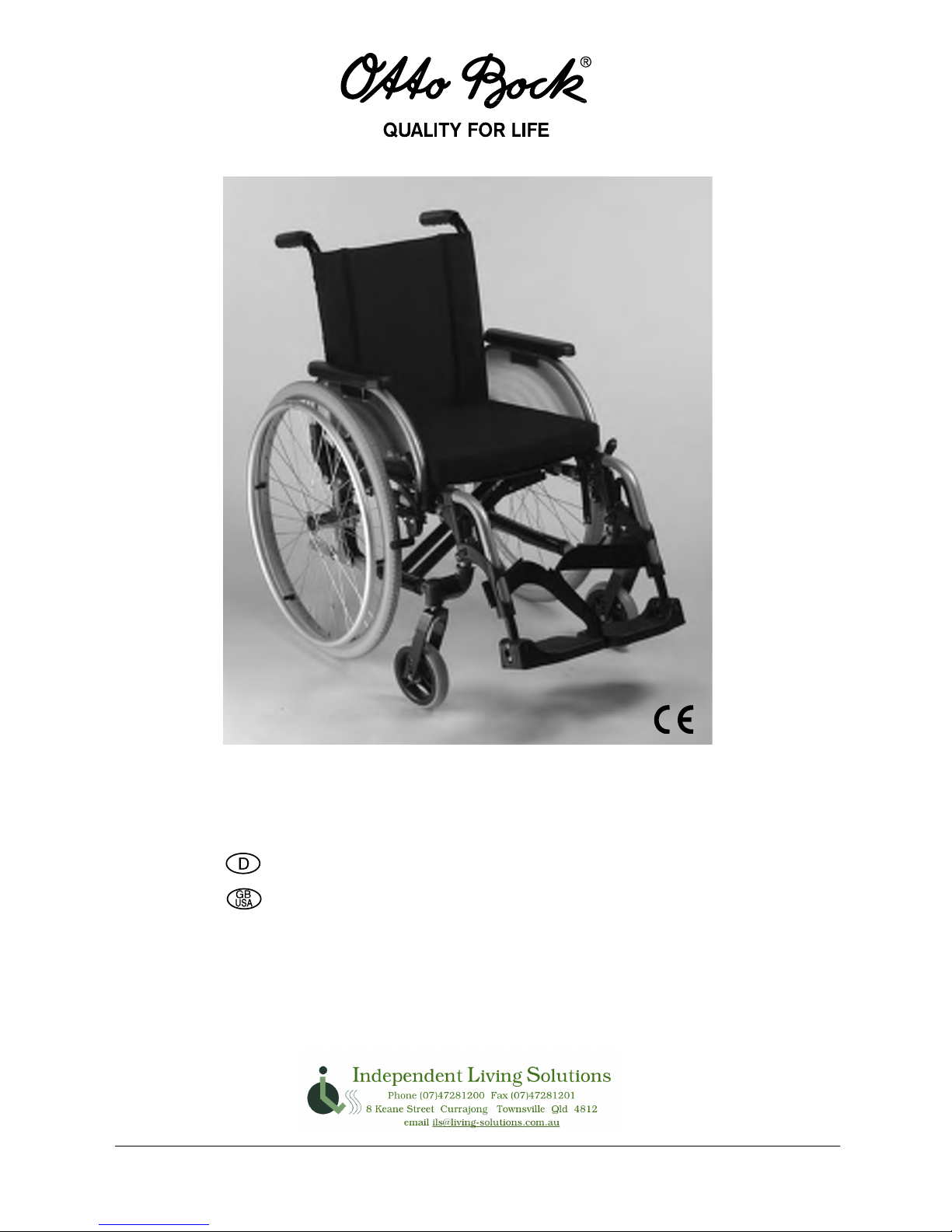
Bedienungsanleitung ................................................ 1
Instructions forUse ..............................................37
© Otto Bock HealthCare GmbH · 647G324=D/GB – 04.06 · Printed in Germany
M1 Intro · M2 Effect · M3 Hemi · M4 XXL · M5 Comfort · M6 Junior
Page 2

37
Instructions for Use for the Start series
Contents
Page
1 General Information .................................................................................................... 39
1.1 Preface .................................................................................................................. 39
1.2 Intended Use ........................................................................................................39
1.3 Field of Application ..............................................................................................39
1.4 Declaration of Conformity ....................................................................................40
1.5 Liability .................................................................................................................40
2 Safety Instructions ...................................................................................................... 40
2.1 Symbol Legend .....................................................................................................40
2.2 General Safety Instructions ................................................................................. 41
3 Delivery / Preparing the Wheelchair for Use ............................................................. 44
4 Folding – Transport ..................................................................................................... 45
5 Accessories ................................................................................................................ 46
5.1 Anti-tipper.............................................................................................................. 46
5.2 Transport wheels...................................................................................................47
5.3 Crutch holder with hook and loop strap............................................................... 47
3IDEPANELSÅIPUPANDREMOVABLE..................................................................... 47
0LUGONWHEELLOCKLEVEREXTENSION ...................................................................... 47
5.6 Drum brakes ......................................................................................................... 47
5.7 Wheel lock for one-handed operation ..................................................................48
5.8 Tray........................................................................................................................48
5.9 Lap belt ................................................................................................................. 48
%LEVATINGFOOTREST ................................................................................................ 48
0USHHANDLESHEIGHTADJUSTABLEREMOVABLE .................................................... 49
7HEELBASEEXTENSION .......................................................................................... 49
5.13 Back upholstery, adaptable ................................................................................50
5.14 Folding back ........................................................................................................ 50
5.15 Spoke protectors.................................................................................................50
5.16 Amputation legrest..............................................................................................50
5.17 Infusion stand......................................................................................................50
5.18 The Back .............................................................................................................50
5.19 The Seat ..............................................................................................................50
Page 3

38
6 Adjustment / Assembly Instructions .......................................................................... 51
6.1 Adjusting seat height and seat inclincation.......................................................... 51
6.2 Changing the wheelbase ...................................................................................... 52
6.3 Caster wheels ....................................................................................................... 53
6.4 Wheel lock............................................................................................................. 54
6.5 Adjusting the brake force for rear wheel with drum brake................................... 55
6.6 Adjusting the angle of the footplate .....................................................................55
6.7 Adjusting the height of the footrest ......................................................................56
!DJUSTINGTHEANGLEOFTHEELEVATINGFOOTREST........................................................ 57
6.9 Adjusting the height of the armrest for desk side panel ...................................... 57
6.10 Adjusting the seat depth ..................................................................................... 57
6.11 Adjusting the back height.................................................................................... 58
6.12 Seat upholstery ................................................................................................... 59
6.13 Adapting the back upholstery .............................................................................59
3ETTINGREARWHEELTRACKING-.........................................................................60
7 Maintenance, Cleaning and Care ............................................................................... 61
8 Changing Tires ............................................................................................................ 62
9 Technical Data............................................................................................................. 64
Page 4

39
1 General Information
1.1 Preface
Congratulations on choosing a lightweight wheelchair from the Start series, a high-quality product that offers versatile applications for everyday use at home and outdoors. Before using your
wheelchair, it is essential to read the sections “Delivery / Preparing the Wheelchair for Use” and
“Safety Instructions” .
The section “Accessories” presents additional components of the Start which can expand its
field of application and improve its comfort. The section “Adjustment / Assembly Instructions”
provides an overview of the possibilities to customize the wheelchair to your personal needs
and preferences. The model as described in these Instructions for Use is subject to technical
changes without notice.
1.2 Intended Use
The lightweight wheelchairs of the Start series are designed solely for people who are unable to
walk or who have a walking impediment. The wheelchairs can be moved either by the patients
themselves or by another person.
The Otto Bock warranty applies only when the product is used according to the specified conditions and for the intended purposes, following all manufacturer‘s recommendations.
1.3 Field of Application
The versatility of the Start series wheelchairs and their modular design make them suitable for
patients who have walking impediments or walking inabilities due to:
• Paralyses
• Loss of limbs (lower limb amputation)
• Defective or deformed limbs
• Joint contractures or defects
• Diseases such as cardiac or circulatory insufficiency, balance disorders or cachexia as well
as for geriatric patients who still have usable residual strength in the upper limbs.
Page 5
40
Fitting considerations:
• Body height and body weight (max. load 125 kg (for M4 XXL: 160 kg,
for M6 Junior: 90 kg))
• Physical and psychological limitations
• Age of the patient
• Home and living conditions
• Environment
1.4 Declaration of Conformity
Otto Bock HealthCare GmbH as manufacturer with sole responsibility declares that the lightweight wheelchairs of the Start series conform to the requirements of the European Directive for
Medical Products 93/42 EEC.
1.5 Liability
Otto Bock HealthCare GmbH assumes liability only if the product‘s instructions for use, adjustment and assembly instructions and regulations have been observed. It is therefore recommended
to use and maintain the product according to the instructions for use.
2 Safety Instructions
2.1. Symbol Legend
DANGER!
Warning messages regarding possible risks of accident or injury.
CAUTION!
Warning messages regarding possible technical damages.
INFORMATION!
Information for operating the product.
INFORMATION!
Information for service staff.
ATTENTION!
Read the Instructions for Use first!
Page 6
41
2.2 General Safety Instructions
DANGER!
To avoid t ippi ng and d ange rous s itu atio ns, famil iar ize your self w ith your new whe elc hair
by practicing on level ground first.
DANGER!
Do not use the footplates as a step stool when getting into or out of your wheelchair.
These should be flipped and swung out of the way first, if possible.
DANGER!
Depending on the diameter and setting of the casters as well as the setting of the
wheelchair’s center of gravity, the casters may flutter when driving at higher speeds.
This can lead to blocking of the casters and cause the wheelchair to tip over. Therefore,
ensure that the casters are properly adjusted (see section “Adjustment / Assembly
Instructions”).
Especially on slopes, do not drive without braking and reduce your speed.
DANGER!
Get to know how the wheelchair reacts when the center of gravity shifts; for example
on slopes or inclines or when clearing obstacles such as steps and curbs. This should
be done only with assistance from another person.
Using the anti-tipper is strongly recommended for untrained wheelchair users.
DANGER!
The anti-tipper is designed to prevent the wheelchair from tipping backwards. Under
no condition should the anti-tipper be used as transport wheels, e.g.when wanting
to push the wheelchair while the rear wheels are removed.
DANGER!
Extreme settings (e.g. rear wheels mounted in the foremost position, M4 / M5)
combined with disadvantageous body postures can tip the wheelchair even when
on level ground.
DANGER!
When ascending slopes, lean your upper body far forward.
DANGER!
When reaching for objects in front, to the side or behind the wheelchair, do not lean
out of the wheelchair too far as this will shift the center of gravity and cause the
chair to tilt or tip over.
DANGER!
Use your wheelchair properly. For instance, do not “jump” the chair down from
higher surfaces and do not drive against obstacles such as steps and curbs without
braking.
Page 7
42
DANGER!
Do not ascend or descend stairs without the assistance of attendants. Make use
of ramps or elevators whenever available. If wheelchair-friendly access is missing,
two attendants must carry the wheelchair over the obstacle.
If only one attendant is available, he or she must adjust the anti-tipper (if mounted)
such that it does not come in the way of the steps during transport. Failure to observe
this precaution can lead to severe falls. Afterwards, the anti-tipper should be swung
back to its operational position.
DANGER!
Advise attendants to lift your wheelchair only by parts that are firmly attached (e.g.
not at the footrest or the flip-up side panels).
DANGER!
If your wheelchair is equipped with height-adjustable push handles, ensure that the
clamping levers are firmly tightened.
DANGER!
When using lifting platforms, ensure that the anti-tipper is outside the dangerarea.
DANGER!
Engage the wheel locks to prevent the wheelchair from moving on uneven ground or
during transfers (e.g. into a car).
DANGER!
Before starting your wheelchair, check the tires for proper inflation levels. The required
air pressure is printed on the side of the tire. For rear wheels, it should be at least
3.5 bar (350 kPa). The wheel locks are only effective with sufficient air pressure and
proper adjustment (approx. 4 mm distance, subject to technical changes).
DANGER!
For transfemoral amputees, the rear wheels must be shifted backwards.
ATTENTION!
If your seat and back upholstery become worn out or damaged, replace it promptly.
With a new seat upholstery you will automatically receive new lamellar plugs for the
seat tube which you should replace for the previously used, old lamellar plugs.
DANGER!
Use caution near flammables or fire, especially lit cigarettes. The seat and backrest
upholstery might catch fire.
DANGER!
To avoid hand inju ries, do not g rasp betw een t he re ar wh eel a nd t he wh eel l ock
when driving your wheelchair.
DANGER!
The maximum load for modules M1, M2, M3 and M5 is 125 kg.
The maximum load for module M4 is 160 kg and for module M6 90 kg.
Page 8
43
DANGER!
Using your Otto Bock product as a seat for transportation in motor vehicles for
disabled passengers
Whenever possible, users should be transferred to the seats installed in the
motor vehicle for disabled passengers. The corresponding restraint systems
should also be used. Only this can ensure optimal protection of the passengers
in case of an accident.
The modules M1, M2, M3, M5 and M6 are permissible for transporting passengers
in motor vehicles when using Otto Bock safety components and when using
appropriate restraint systems.
For more information, please refer to our instructions for use manual “Using your
Wheelchair/ Mobility Base with Seating Shell or Buggy/Stroller as a Seat for
Transp ortation in Motor Ve hic les”, ord er no. 646 D158.
DANGER!
Always make sure that the quick-release axles are correctly set on the rear wheel.
The rear wheel must not be removable without the button of the quick-release axle
being depressed.
DANGER!
Slowing down from high speeds or when descending longer slopes tends to heat
up the hands and fingers, especially if using aluminum push rings.
INFORMATION!
When using your wheelchair outdoors, wear leather gloves. Gloves provide you with
a better grip and protect your fingers from dirt and hot metal.
INFORMATION!
The effectiveness of the wheel lock and the overall driving quality are dependent on
adequate air pressure.
Properly inflated rear wheel tires and equal air pressure in both tires considerably
improve the maneuverability of your wheelchair.
INFORMATION!
Ensure that the tires have sufficient tread depth.
When using your wheelchair in public traffic, you are subjected to public traffic
regulations.
INFORMATION!
Ensure you are visible in the dark. If possible, wear light-colored clothes or clothing
with reflectors, and ensure that the reflectors installed at the side and the rear of the
wheelchair are clearly visible. We also recommend installing lights.
Page 9
44
1 2
3 Delivery / Preparing the Wheelchair for Use
DANGER!
Risk of injury: Do not hold on to other moveable parts than the ones described.
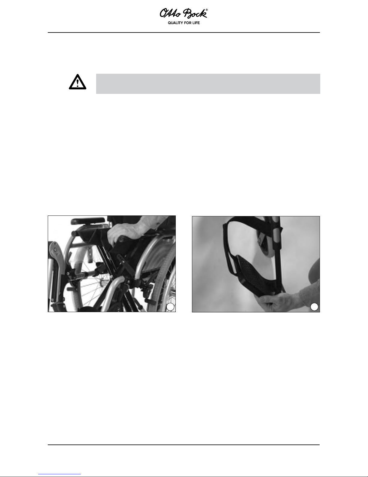
Wheelchairs of the Start series are generally delivered completely assembled and folded.
Three simple steps prepare it for use:
1) When folding or unfolding the wheelchair, hold it only at the indicated positions (Fig. 1,
Fig. 3).
2) While standing next to the wheelchair, tip it slightly toward you and press on the edge of
the seat upholstery closest to you. The wheelchair will unfold up to its entire seat width
(Fig. 1).
3) Push the footplates down (Fig. 2).
The overhang of the back upholstery attaches easily to the seat upholstery with a hook-and-loop
closure. We recommend keeping the overhang attached at all times.
Page 10
45
4 Folding – Transport
INFORMATION!
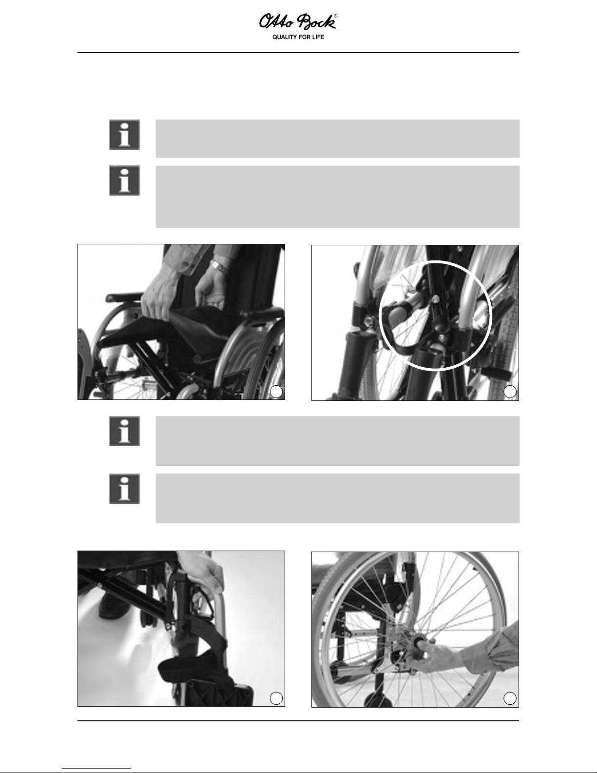
Flip up the footplates. Grab the seat upholstery at the front and the back in the middle and
pull it upwards. The wheelchair then folds into itself (Fig. 3).
INFORMATION!
Once the wheelchair is folded, secure the strap of the folding fixture with the snap fastener.
This will prevent the wheelchair from unfolding unexpectedly (Fig. 3A).
For more manageable transportation, e.g. in cars, the footrests can be swung inwards or
outwards or be entirely removed.
3 3A
INFORMATION!
To move or r emove the footres t, pull th e l ock rele ase a ssist (Fig . 4) to t he rear.
The footrest with footplate can then be swung inwards or outwards or be removed by pulling it upward.
INFORMATION!
During reassembly, ensure that the footrest locking device has engaged. Transportation is
greatly facilitated by the removable quick-release axles on the rear wheels (included in the
standard version) (Fig. 5).
4 5
Page 11
46
INFORMATION!
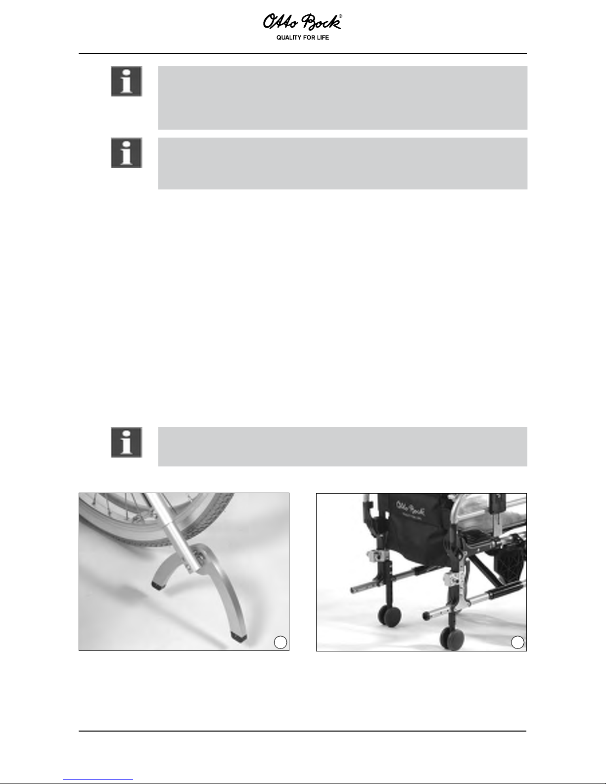
Slide four fingers between the spokes near the hub of the rear wheel. Then press
the button of the quick-release axle with your thumb. You can then easily pull off
the rear wheel.
Follow the corresponding procedure when remounting.
INFORMATION!
When remounting, be sure the quick-release axle securely locks into the quickrelease axle housing.
The rear wheel must not be removable when the button is not being pressed!
5 Accessories
The wheelchair is designed as a modular assembly system. This means that certain accessories
can be adapted to your wheelchair. In the following, we will present you a selection of our variants and accessories which improve the use and comfort of your wheelchair.
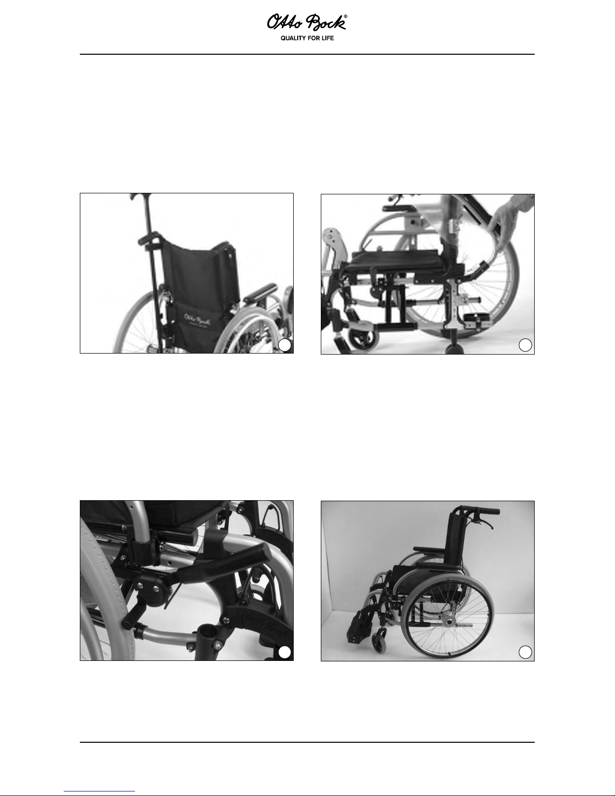
5.1. Anti-tipper (Fig. 6)
Prevents the wheelchair from tipping too far backward. Strongly recommended for untrained
wheelchair users as well as when extreme adjustments have been made to the rear wheel.
5.2. Transport wheels (Fig. 7)
With the rear wheels removed, the wheelchair can be used as a rolling base. This allows maneuvering through narrow passage ways (such as bathroom doorways or airplane aisles).
INFORMATION!
Please note that once the rear wheels are removed, the wheel locks can no longer
be activated!
6 7
Page 12
47
8 9
5.3. Crutch holder with hook and loop strap (Fig. 8)
3IDEPANELSÅIPUPANDREMOVABLE (Fig. 9)
Available in several models, also with height-adjustable armrests; side panels can be flipped
up or removed for getting into or out of the wheelchair. To flip up the side panel, manipulate the
release lever behind the side panel tube.
0LUGONWHEELLOCKLEVEREXTENSION (Fig. 10)
Facilitates use of the wheel lock.
5.6. Drum brakes (Fig. 11)
Allow the attendant to comfortably and safely brake the wheelchair. The rear wheels remain
removable via the quick-release axle system.
10 11
Page 13
48
12 13
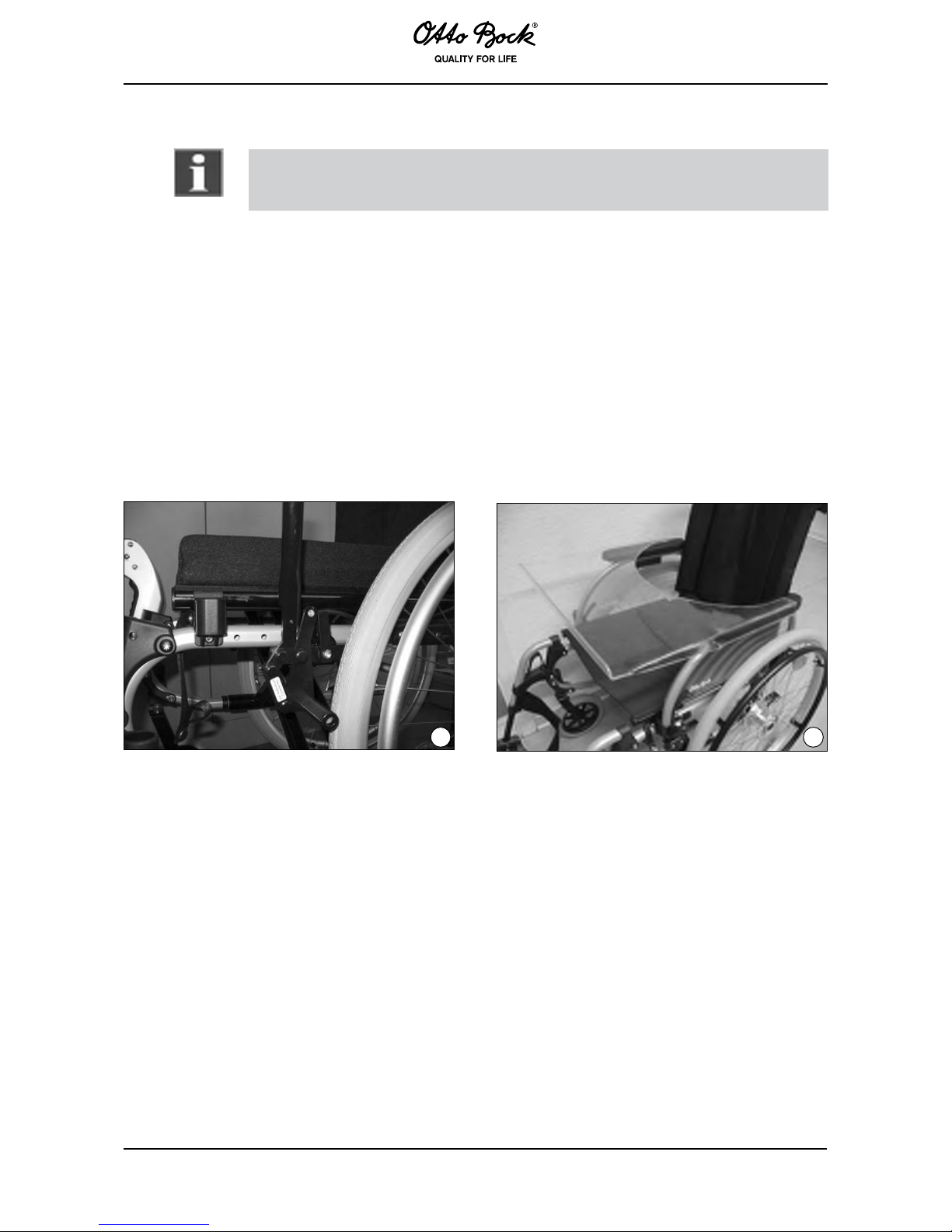
5.7. Wheel lock for one-handed operation (Fig. 12)
INFORMATION!
Please note that the wheel lock lever extension must always be attached when
releasing or engaging the wheel lock.
Recommended especially for hemiplegics. It can be activated either on the right or left side and
ensures the safe locking of both rear wheels with a pull-wire system.
5.8. Tray (Fig. 13)
Serves as a supporting surface during meals, when working or when playing. The clear material
allows visibility of the legs and correction of the sitting posture.
5.9. Lap belt (Fig. 14)
Prevents the wheelchair user from falling out of the wheelchair.
%LEVATINGFOOTREST (Fig. 15)
Allows positioning of the leg at different angles. Upon manipulation of the release lever which is
integrated into the legrest bearing the footrest angle can be adjusted in small increments.
Page 14
49
14 15
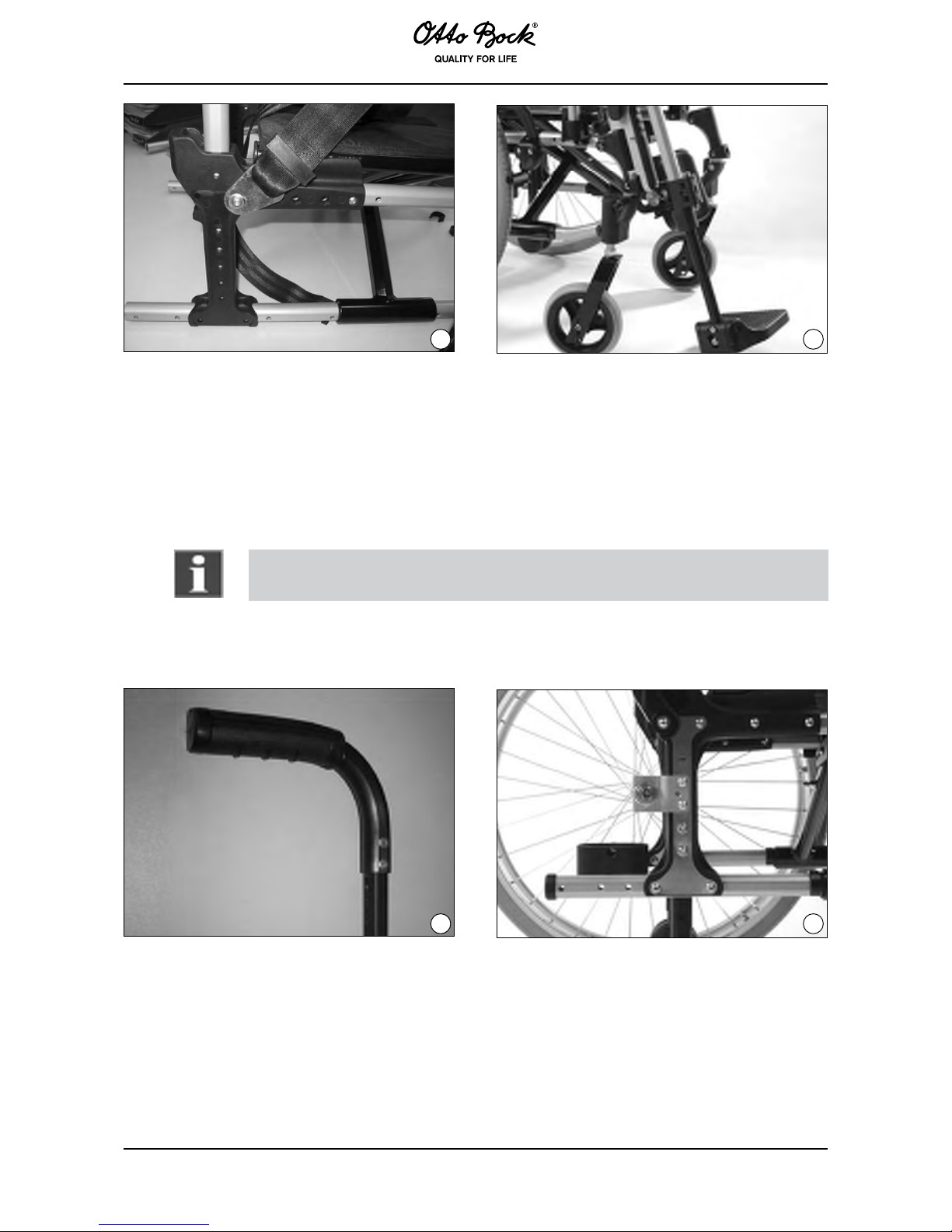
5.11 Push handles, height-adjustable (Fig. 16)
Can be adjusted vertically to a more comfortable height for the attendant.
5.12 Wheelbase long (Fig. 17)
Makes the wheelchair particularly stable against tipping, increases the turning range.
INFORMATION:
For transfemoral amputees the long wheelbase setting is indispensable.
16 17
Page 15
50
18 19
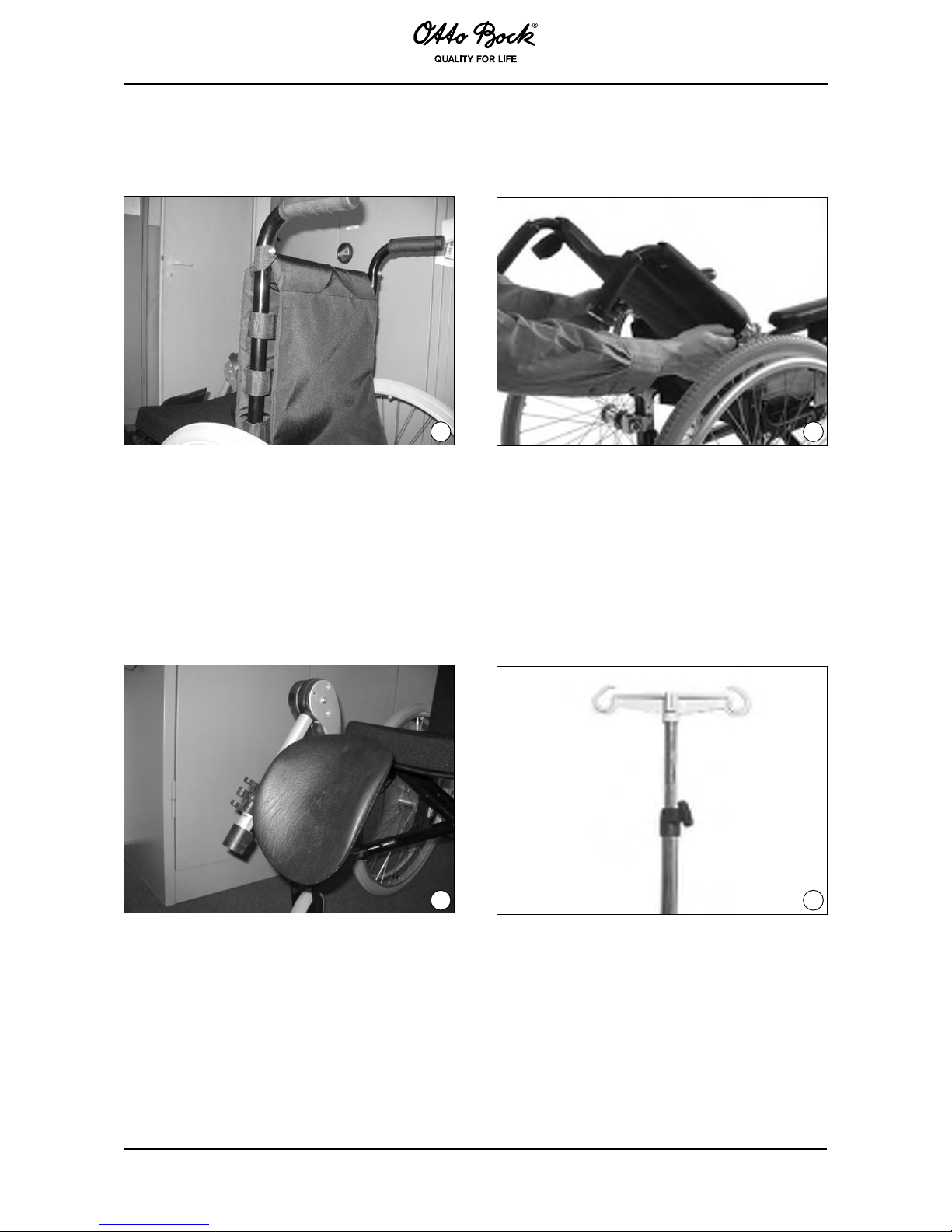
5.15 Spoke protectors
Protect the fingers from getting caught in thewheelspokes.Alsoimprovetheappearanceof
the wheelchair.
5.16 Amputation legrest (Fig. 20)
5.17 Infusion stand (Fig. 21)
20 21
5.18 The Back (Fig. 22)
Firm back to support positioning (see 647H491 Instructions for Use).
5.19 The Seat (Fig. 23)
Seat base with variable setting possibilities to improve positioning (see 647H450 Instructions
for Use).
5.13 Back upholstery, adaptable (Fig. 18)
5.14 Folding back (Fig. 19)
Page 16
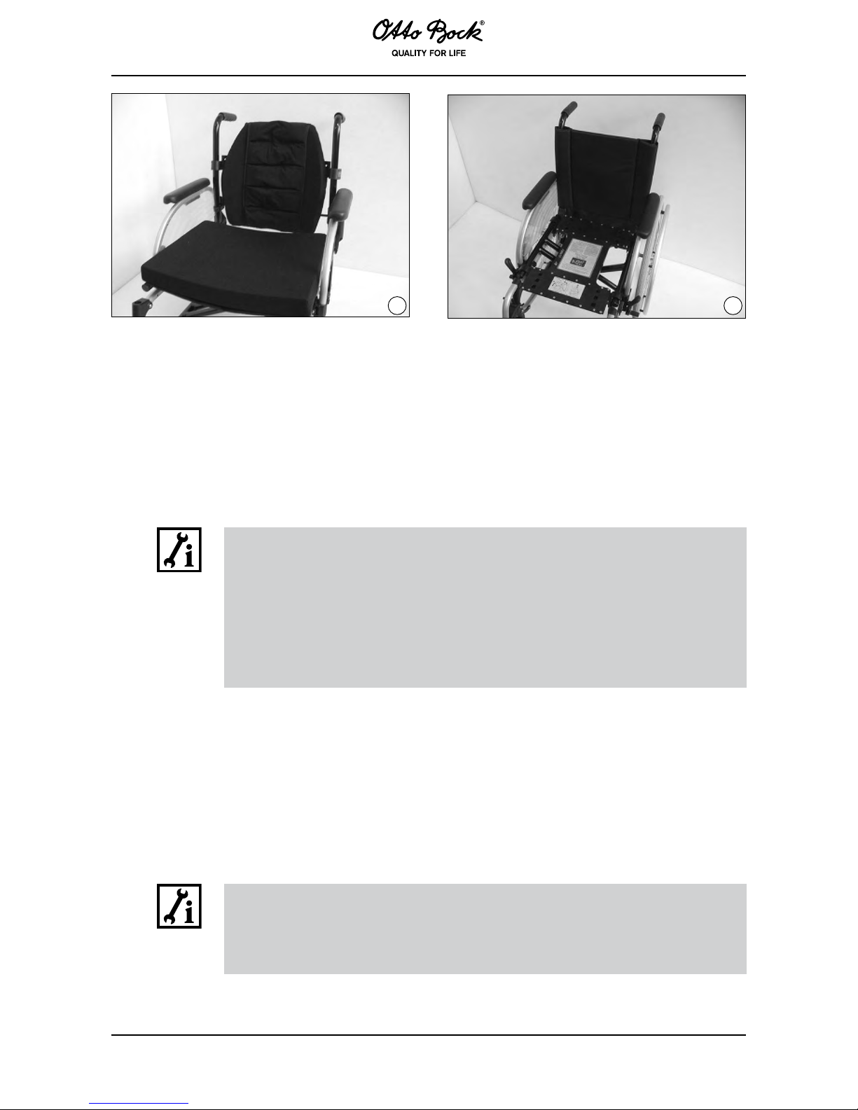
51
22 23
6 Adjustment / Assembly Instructions
All wheelchair users have expectations regardingwheelchairtype,accessories,seatingand
handling.
Your Start wheelchair has many options by which it can be customized to your needs and preferences. We recommend consulting with your dealer or therapist to determine which wheelchair
settings will work best for you.
INFORMATION!
The following tools are required for repair and maintenance:
• Allen wrenches, sizes 4 and 5 mm
• Torx Allen wrenches, sizes x 30
• Open-end wrenches, sizes 19 and 24 mm
• Socket wrenches, sizes 10 and 19 mm
• Phillips head screwdriver
• Tire levers
• Torque wrench
6.1. Adjusting seat height and seat inclination
The higher the rear wheel is attached to the frame, the more the seat inclines downward. This
positions the user deeper and more firmly into the seat. However, rear wheels that are attached
high at the frame also make the wheelchair more prone to tilt backwards. A careful and synchronized height adjustment of both the rear wheels and the casters will allow to adapt the seat
height to the user’s individual requirements.
INFORMATION:
Please note: When the rear wheel position is changed, the angle of the caster axle
in relation to the ground also changes. Ensure that this angle is always approx.
90° wide (see “Caster wheels”). The wheel lock must be re-adjusted as well (see
“Wheel lock”) .
Page 17
52
INFORMATION:
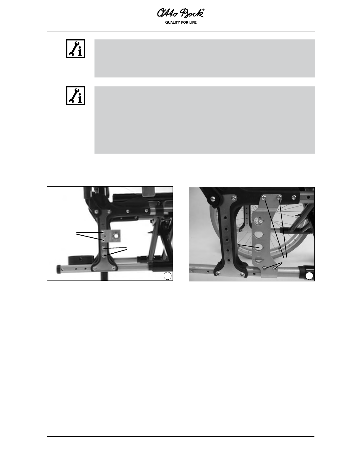
The Start M1 Intro, M2 Effect, M3 Hemi and M6 Junior offer the possibility to
change the vertical position of the rear wheel by shifting the rear wheel adapter
along the frame. Loosen the two screw connections A (Fig. 24) and remove the
screws. Shift the adapter to the desired position and firmly retighten the screws.
INFORMATION:
Make sure to firmly retighten all screws and nuts after making adjustments. The
proper torque for the screw connection of the rear wheel adapter is 8 Nm. The
proper torque for the screw connection of the fitting is 50 Nm.
For Start M4 XXL and M5 Comfort: Loosen the nut A (Fig. 25) of the quickrelease axle housing on the inside of the frame and remount the axle housing at
the desired position. The proper torque is 50 Nm. The distance between rear
wheel and side panel can be continuously adjusted by adjusting the counter nut on
the outer side of the frame.
24 25
A
B
6.2 Changing the wheelbase
Shifting the rear wheel backwards lengthens the wheelbase and thus provides for greater stability of the wheelchair. Shifting the rear wheel forwards (only for advanced wheelchair drivers!)
relieves the load on the casters. This increases themaneuverabilityofthewheelchair.Thecaster
wheels can then also be lifted more easily to clear obstacles such as curbs or steps.
B
A
Page 18
53
DANGER!
Please note: If the rear wheels are in a more forward position and the user’s body
is not appropriately positioned, the user may tip backward - even on level ground!
DANGER!
For untrained wheelchair users and when there are extreme adjustments to the
rear wheel, an anti-tipper is strongly recommended!
DANGER!
For transfemoral amputees it is essential to shift the rear wheels backwards!
INFORMATION!
For Start M1 Intro, M2 Effect, M3 Hemi and M6 Junior: Loosen the screws A of
the rear wheel adapter (Fig. 24) at the frame and mount the rear wheel adapter
(with sides reversed) in the desired position. The distance between rear wheel and
side panel can be continuously adjusted by adjusting the counter nut on the outer
side of the frame.
INFORMATION!
Make sure to firmly retighten all screws and nuts after making adjustments. The
proper torque of the screw connection of the rear wheel adapter is 8 Nm.
INFORMATION!
For Start M4 XXL and M5 Comfort: Loosen and remove the 4 screw
connections B (Fig. 25) which connect the rear wheel adapter to the frame. The
adapter can then be shifted to the desired position on the frame tube and the
plastic adapter.
When changing the adjustments originally made in the factory, two other component groups of
the wheelchair must be readjusted, refer to sections 6.3 and 6.4.
6.3 Caster wheels
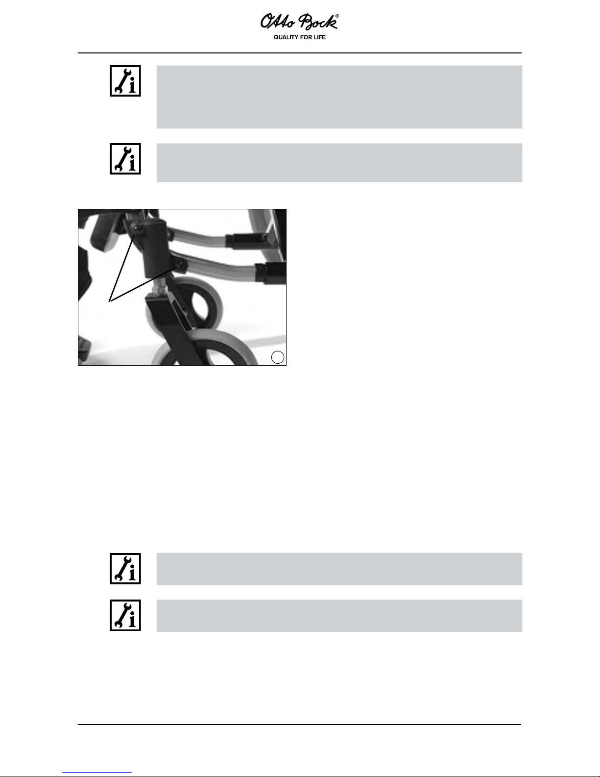
Adjusting the caster wheel journal angle
(Fig. 26)
After the rear wheels have been mounted in the appropriate position, the caster wheel journal
angle must be readjusted.
The threaded axle should be as horizontal as possible in relation to the ground to ensure optimal
driving behavior of the wheelchair. The caster adapter allows for continuous angle adjustment.
Page 19
54
INFORMATION!
Loosen the two screws A between caster adapter and frame (Fig. 26).
Now you can move the caster adapter along the frame tube. The level (included
in delivery) will help you position the threaded axle as vertically to the ground as
possible.
INFORMATION!
Make sure to firmly retighten all oval head screws. The proper torque is 8 Nm
(Fig. 26).
26
A
6.4 Wheel lock
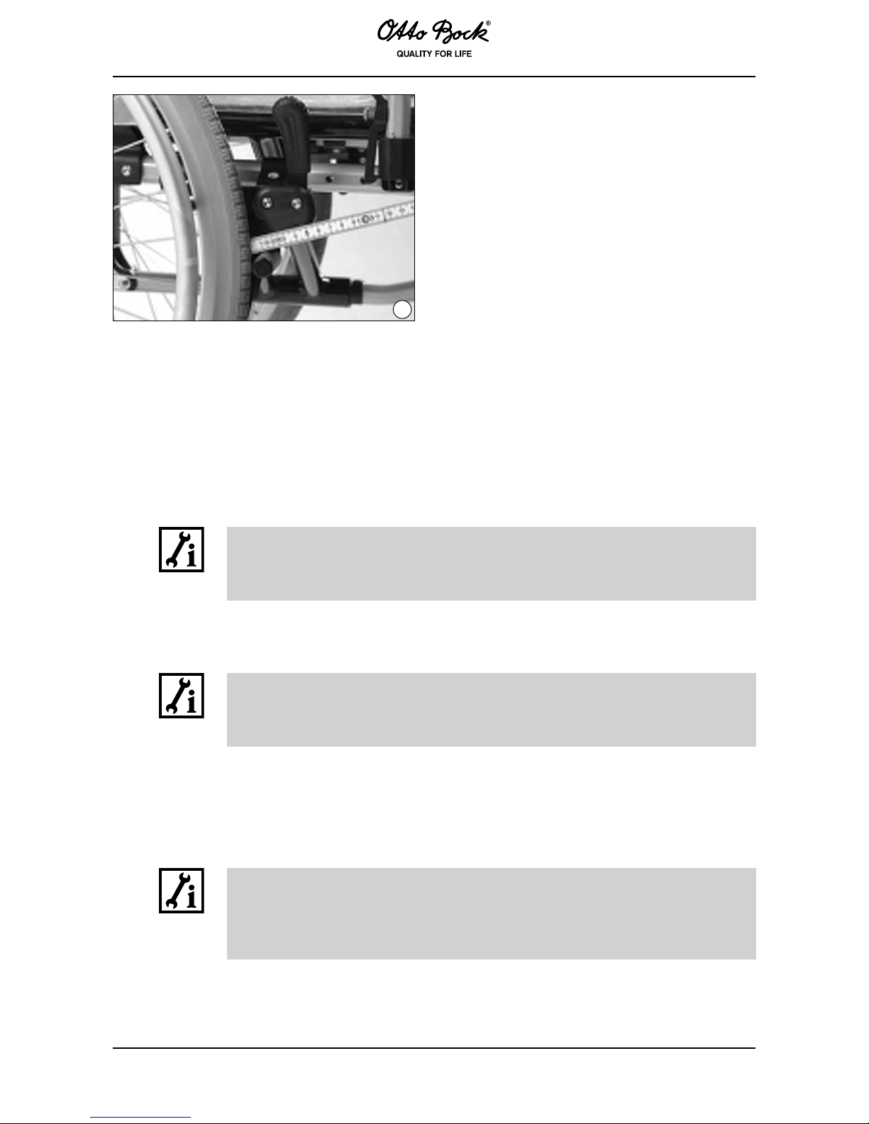
To change the position of the rear wheels, first loosen the attachment screws of the clamping
adapters of the wheel lock and push the wheel lock forward. Then reposition the rear wheels. The
wheel lock should then be remounted such that the distance between the tires and wheel lock
bolts is max. 4 mm when the wheel lock is not activated (subject to technical changes) (Fig. 27).
Check the tire air pressure and the effectiveness of the locking devices regularly. The proper
air pressure is indicated on the side wall of the tire. It should be at least 3.5 bar (350 kPa). To
ensure sufficient braking effect, use only original rear wheels with an approved radial excursion
of maximally±1mm.
INFORMATION!
Make sure to firmly retighten all screws and nuts after making adjustments!
INFORMATION!
Tighten the wheel lock attachment with a torque of 10 Nm.
Page 20
55
27
4mm
6.5 Adjusting the brake force for rear wheel with drum brake
The brake force is adjusted at the adjustment screw to achieve optimal braking effect. The brake
force is increased by turning the screw counter-clockwise and decreased by turning the screw
clockwise.
INFORMATION!
Turn the adjustment screw counter-clockwise until frictional noise occurs at
the turning wheel. Then tighten the adjustment screw until the frictional noise
disappears. The wheel should run freely.
After finishing the adjustment, fasten the adjustment screw by tightening the counter nut.
INFORMATION!
Ensure that the brake force of both rear wheels is adjusted equally.
Also make sure that the drum brake engages with sufficient force only when the
manual brake lever is set to the second ratchet position.
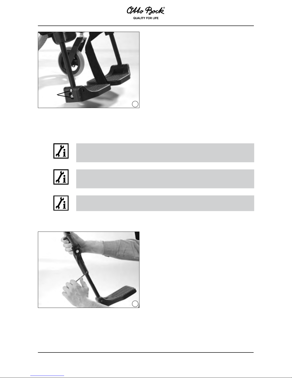
6.6 Adjusting the angle of the footplate (Fig. 28)
INFORMATION!
Prior to adjusting the footplate angle, loosen the screw connections A as indicated
in the figure.
Then set the footplate to the desired angles and tighten the loosened screw
connections with a torque of 6 Nm.
Page 21
56
28
A
6.7 Adjusting the height of the footrest (Fig. 29)
INFORMATION!
By loosening the set screw, the footplate can be adapted to your lower leg length
and to the thickness of your seat cushion.
Make sure when adjusting the footrest height, that the footrest bar is slid into the
swivel segment at least 40 mm. A marking on the footrest bar indicates how far
the bar should be slid in.
INFORMATION!
After having made adjustments, retighten the set screw to a torque of 6 Nm.
29
Page 22
57
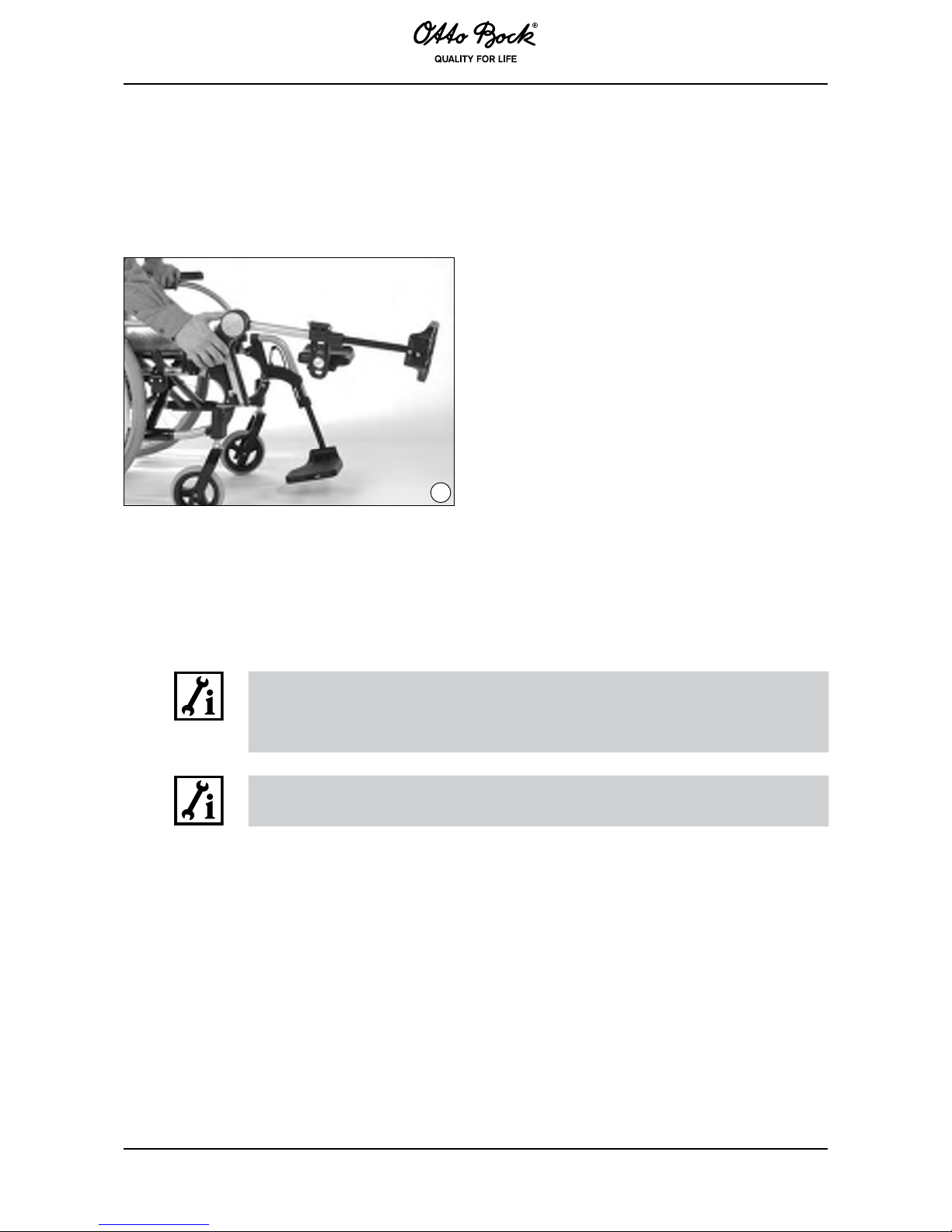
!DJUSTINGTHEANGLEOFTHEELEVATINGFOOTREST (Fig. 30)
Turn the release lever until it hits the stop. While propping up the footrest bar, set the desired
angle. Then carefully let the release lever turn back. At the next free position, the footrest will
snap into place.
30
6.9 Adjusting the height of the armrest for desk side panel
The armrest can be set to three different heights. In the standard assembly, the armrest is
mounted firmly onto the tube bend.
INFORMATION!
To increase the armrest height, remove the two cap screws completely from the
tube bend. Then place the two distance pieces above the tube bend between
armrest and side panel tube to adjust a further height.
INFORMATION!
Make sure to firmly retighten all screws and nuts after making adjustments.
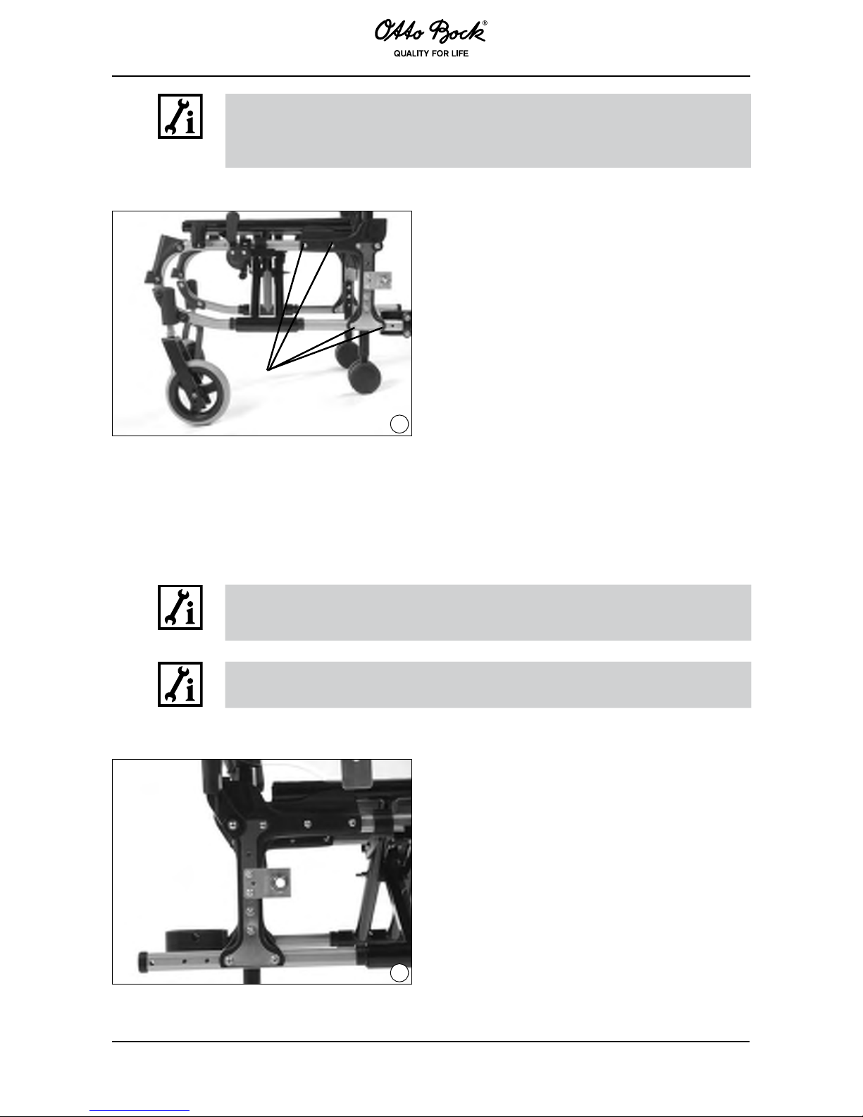
6.10 Adjusting the seat depth (Fig. 31)
Undo the hook-and-loop attachment between back padding and seat upholstery.
Loosen the screw connections A that connect the rear wheel adapter to the open frame tube.
Remove the screws. The rear wheel adapter can then be shifted along the frame tube. Three
different seat depth adjustments, in 3 cm increments, are possible.
Page 23
58
INFORMATION!
Make sure to firmly retighten all screws and nuts after making adjustments (6 Nm).
Fasten the hook-and-loop attachment again between the back padding and the
seat upholstery.
31
A
6.11 Adjusting the back height (Fig. 32)
The back tube which is integrated into the posterior frame allows for the adjustment of the back
height in increments of 2.5 cm.
INFORMATION!
Remove the screws A and B from the rear wheel adapter.
Set the desired back height.
INFORMATION!
Make sure to firmly retighten all screws and nuts after making adjustments (8 Nm).
32
Page 24

59
6.12 Seat upholstery (no figure)
Should your seat upholstery become stretched out after longer use, contact your dealer to have
it replaced with a new seat upholstery.
6.13 Adapting the back upholstery (Fig. 33)
If you have selected the option “adaptable back upholstery”, you can adjust the back upholstery
in segments according to your needs.
INFORMATION!
To do this, remove the back upholstery padding and undo the hook-and-loop
fasteners of the straps. Reposition the straps as desired, attach them again with
the hook-and-loop fasteners and cover with the padding.
33
DANGER!
Using your Otto Bock product as a seat for transportation in motor vehicles for
disabled passengers
Whenever possible, users should be transferred to the seats installed in the motor
vehicle for disabled passengers. The corresponding restraint systems should also
be used. Only this can ensure optimal protection of the passengers in case of an
accident.
The modules M1, M2, M3, M5 and M6 have been approved as transportation seats in
motor vehicles for the disabled under the condition that Otto Bock safety components
as well as appropriate restraint systems are used.
For more information, please refer to our instructions for use manual “Using your Wheelchair/
Mobility Base with Seating Shell or Buggy/Stroller as a Seat for Transportation in Motor
Vehicles”, order no. 646D158.
Page 25
60
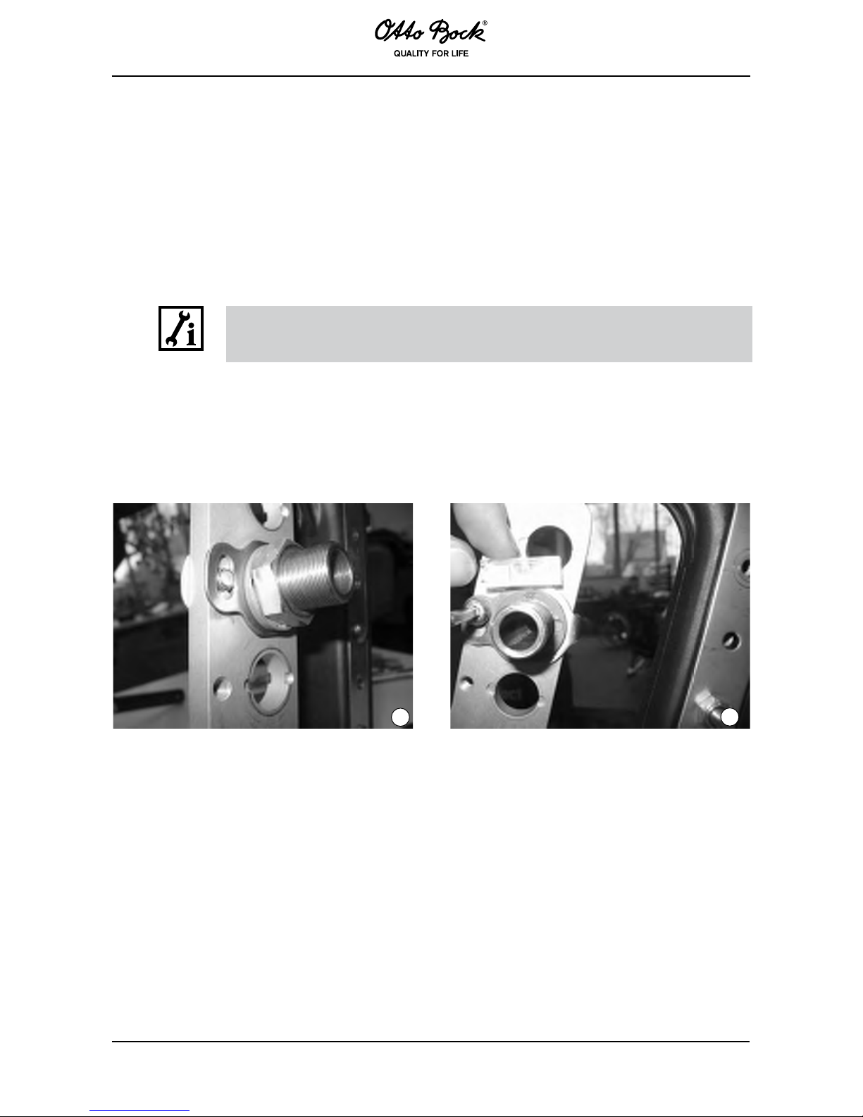
6.14 Setting rear wheel tracking (M5) (Fig. 34, 35)
The correction plate, which is angled twice, is to be mounted to the adapter with the rear
wheel fitting and the camber washers. To correct wheel tracking, put the level on the straight To correct wheel tracking, put the level on the straightTo correct wheel tracking, put the level on the straight
edge of the correction plate and turn the plate until the camber washers are level. Next, fix the Next, fix theNext, fix the
plate with the 6 mm oval head screw. Finally retighten the M18x1 nuts. Finally retighten the M18x1 nuts.Finally retighten the M18x1 nuts.
INFORMATION!
Make sure to firmly retighten all screws and nuts after making adjustments.
Observe the values indicated in section 6.1.
34
35
Page 26

61
7 Maintance, Cleaning and Care
Your Start wheelchair has been provided with the CE marking. The manufacturer herewith
guarantees that this medical product as a whole conforms to the requirements of the European
Directive for Medical Products 93/42/EEC.
The proper function of the wheelchair, especially of the brakes, should be checked before every
use. Safety nuts should be used only once. If they have been loosened several times, they must
be replaced.
In the case of defects, contact your authorized dealer immediately to eliminate them. This applies
in particular when the driving behavior changes or the wheelchair becomes unstable.
We also recommend that you have the wheelchair serviced every 12 months by your Otto Bock
authorized dealer.
The following table lists functions which the user must check at the indicated intervals.
Check before each use monthly quaterly
Function test of the wheel locks/brakes X
Sagging of the seat or back upholstery X
Setting of the caster journal bearing X
Sight-check of wearing parts (e.g. tires, bearings) X
Dirt on bearings X
Push rings for damages X
Air pressure (see indication on tire) X
Folding mechanism for wear and tear X
Spoke tension of the rear wheels X
Screw connections X
Page 27

62
Cleaning
Use only mild detergents to clean your wheelchair.
To ensure smooth operation at all times, the following precautions and cleanings should be carried out. Users may carry these out by themselves.
•Hairanddirtparticlesgenerallyaccumulatebetweenthecasterwheelandfork.Thiscan
restrict the caster wheels from rotating smoothly. Remove the caster and thoroughly clean the
fork and caster using a mild detergent.
• The rear wheels and caster wheels may have been configured as a quick-release axle system.
To keep this system operational, ensure that no dirt adheres to the quick-release axle or axle
housing. The quick-release axle should also be lightly lubricated regularly with resin-free sewing machine oil.
• If your wheelchair gets wet, towel dry it as soon as possible.
• Do not use your wheelchair in salt water and keep sand or other particles from damaging the
wheel bearings.
•Screwconnectionsshouldbecheckedfrequently,inparticularwhenbeginningtousethe
wheelchair and after any adjustment. If a screw connection becomes loose repeatedly, consult
your dealer.
8 Changing Tires
Changing flat tires requires only the necessary tools and minimal technical skills. Users may
change tires themselves if they wish. We recommend carrying an emergency repair set and
an air pump at all times (if using pneumatic tires). Alternatively, users can keep a spray can of
hardening foam (available at bicycle shops) to fill a tire in case of punctures.
• In case of a flat tire, carefully remove the tire from the rim using the appropriate tools.
• Take care not to damage the rim or the inner tube.
•Repairtheinnertubeaccordingtothedirections in the repair kit, or, replace the damaged
inner tube with a new one.
•Beforere-mountingthetire,inspecttheinnerrimsurfaceandtheinsideofthetireforanyobject
that may have caused the puncture.
• Be sure that the rim bands are not damaged. They protect the tube from being damaged by
the ends of the spokes.
Page 28
63
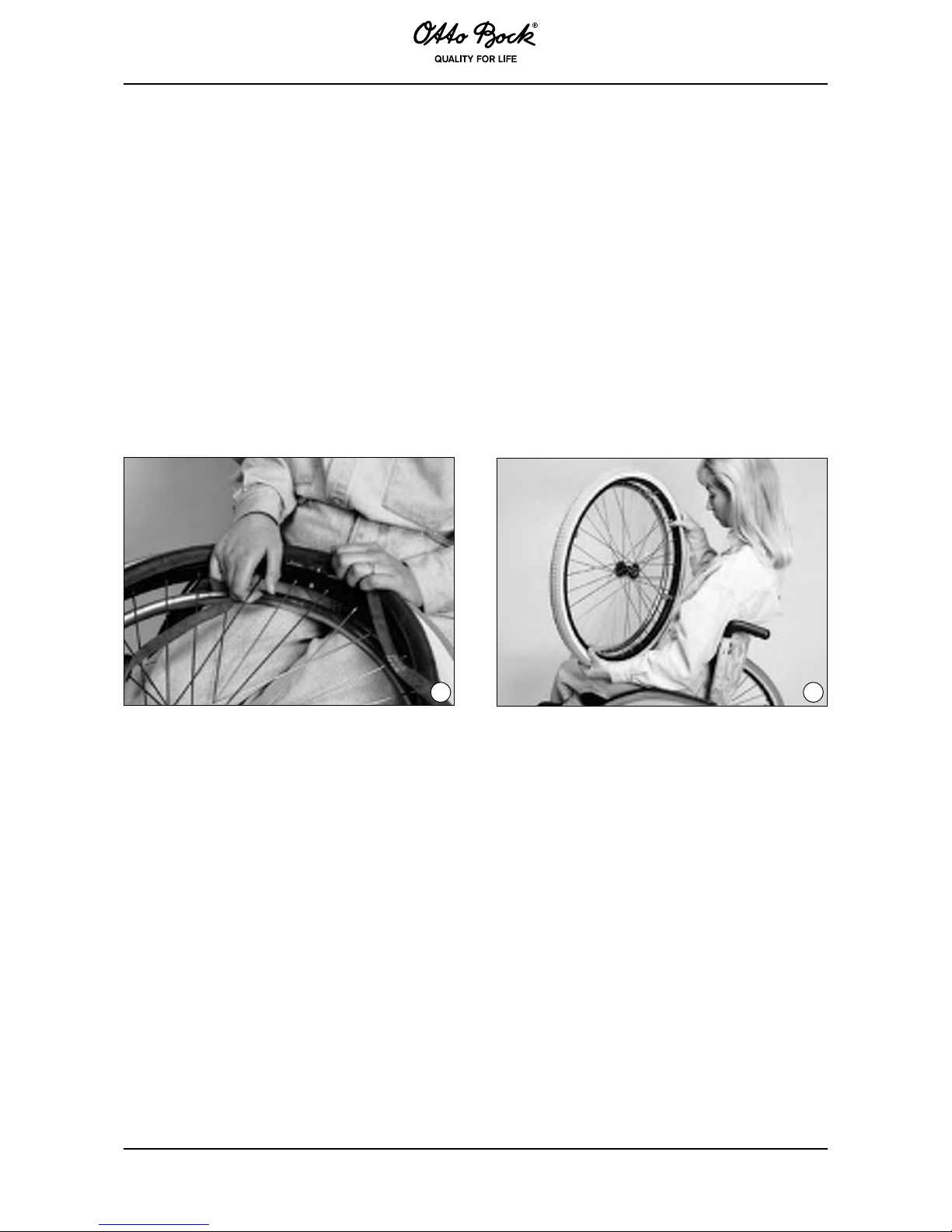
Mounting (Fig. 36)
•Placetheprotectiverimbandoverthevalve.Thenpushthevalvethroughtherim.Screwon
the valve nut, if there is one. The rim band can then be easily applied.
•Ensurethatallspokeendsarecovered.
Tires (Fig. 37)
•Beginningbehindthevalve,placethelowersideofthetireovertheedgeofthewheelrim.
Pump the tube with a small amount of air until it is round. Then insert it in the tire.
•Checktheinnertubeforfolds.Iffoldsarepresent,releasesomeair.Therestofthetirecan
then be mounted by, starting with the section of tire opposite the valve, gently pressing the tire
toward the valve.
36 37
)MÄ@SHMF
• Check around the tire on both sides to ensure that the tube is not clamped between the edge
of the tire and the rim.
Pushthevalvebackslightlyandthenpullitoutagainsuchthatthetireiswell-seatedinthe
valve area.
• Inflate the tire until it can still be pressed easily with your thumb. If the control line on both sides
of the tire is equally distanced to the rim, the tire sits centrally. If the tire does not sit centrally,
let out some air and realign the tire. Then inflate the tire to the pressure indicated on the side
wall and tighten the dust cap.
Page 29

64
9 Technical Data
Overall length (in cm)
Rear wheel size
20x1 3/8” 22x1 3/8” 24x1 3/8”
Module
Rear axle
position
Front axle
position
Rear axle
position
Front axle
position
Rear axle
position
Front axle
position
M1 - - 100 90 103.5 94
M2, M3 - - 100.5 90 104 94
M4 - - 100.5 87.5 104 91
M5 - - 97.5 81.5 101 85
M6 89.5 79 92 81.5 95.5 85
Overall width (in cm)
1)
Seat
width
Standard rear wheel
max.
Rear wheel with drum
brake max.
28 47 49.5
30.5 49.5 52
33 52 54.5
35.5 54.5 57
38 57 59.5
40.5 59.5 62
43 62 64.5
45.5 64.5 67
48 67 69.5
50.5 69.5 72
53 72 74.5
55.5 74.5 77
58 77 79.5
1)
Applicable to push ring attachment, narrow (for push ring attachment, wide: +2 cm) and a 0° camber of the
rear wheels.
Page 30

65
Start M1 Intro
Anterior seat height (in cm)
1)
Position
Caster diameter
6” solid rubber 8” solid rubber
Caster fork
short
Position 1
Position 2
Position 3
Position 4
2)
40.7
42
43.2
2)
2)
2)
45.7
Caster fork
long
Position 4
Position 5
Position 6
Position 7
43.2
44.5
45.7
47
45.7
47
48.2
49.5
1) Indications without seat cushion and with a seat inclination of 0°
2) This combination is not possible
With the spacer sleeve mounted in the lower position, values of table + 2 cm
Free mounting positions
Rear wheel size
24”
1A 41.2
1B 42.2
2A 43.7
2B 44.7
3A 46.2
3B 47.2
4A 48.7
4B 49.7
Page 31

66
Start M2 Effect
Anterior seat height (in cm)
1)
Position
Caster diameter
5.5”
soft
6” solid
rubber
7” 8”
Caster fork
short
Position 1
Position 2
Position 3
Position 4
2)
42
43.5
44.5
2)
42.5
44
45
2)
2)
45.5
46.5
2)
2)
2)
47.5
Caster fork
long
Position 4
Position 5
Position 6
Position 7
44.5
46
47
48.5
45
46.5
47.5
49
46.5
48
49
50.5
47.5
49
50
51.5
1) Indications without seat cushion and with a seat inclination of 0°
2) This combination is not possible
With the spacer sleeve mounted in the lower position, values of table + 2 cm
Free mounting
positions
Rear wheel size
22“ 24“
1A 37.8 41.2
1B 38.8 42.2
2A 40.3 43.7
2B 41.3 44.7
3A 42.8 46.2
3B 43.8 47.2
4A 45.3 48.7
4B 46.3 49.7
Page 32

67
Start M3 Hemi
Anterior seat height (in cm)
1)
Position
Caster diameter
5” solid
rubber
5.5” soft
6” solid
rubber
7” 8”
Caster fork
short
Position 1
Position 2
Position 3
Position 4
36.5
38
39
40.5
2)
39
40
41.5
2)
39.5
40.5
42
2)
2)
42
43.5
2)
2)
2)
44.5
Caster fork
long
Position 4
Position 5
Position 6
Position 7
40.5
41.5
43
44
41.5
42.5
44
45
42
43
44.5
45.5
43.5
44.5
46
47
44.5
45.5
47
48
1) Indications without seat cushion and with a seat inclination of 0°
2) This combination is not possible
Free mounting positions
Rear wheel size
22” 24”
1A 37.8 41.2
1B 38.8 42.2
2A 40.3 43.7
2B 41.3 44.7
3A 42.8 46.2
3B 43.8 47.2
4A 45.3 48.7
4B 46.3 49.7
Page 33

68
Start M4 XXL / M5 Comfort
Anterior seat height (in cm)
1)
Position
Caster diameter
5” solid
rubber
5.5” soft
6” solid
rubber
7” pneum.
tire
8”
Caster fork
short
Position 1
Position 2
Position 3
Position 4
40
41.5
42.5
44
2)
42
43.5
44.5
2)
42.5
44
45
2)
2)
45.5
46.5
2)
2)
2)
47.5
Caster fork
long
Position 4
Position 5
Position 6
Position 7
44
45
46.5
47.5
44.5
46
47
48.5
45
46.5
47.5
49
46.5
48
49
50.5
47.5
49
50
51.5
1) Indications without seat cushion and with a seat inclination of 0°
2) This combination is not possible
With the spacer sleeve mounted in the lower position, values of table + 2 cm
Free mounting positions
Rear wheel size
22” 24”
1 37.7 41.1
2 40.7 44.1
3 43.7 47.1
4 46.7 50.1
Page 34

69
Start M6 Junior
Anterior seat height (in cm)
1)
Position
Caster diameter
5“ solid rubber 6“ solid rubber
Caster fork
short
Position 1
Position 2
Position 3
Position 4
40
41.5
42.5
44
2)
42.5
44
45
Caster fork
long
Position 4
Position 5
Position 6
Position 7
44
45
46.5
47.5
45
46.5
47.5
49
1) Indications without seat cushion and with a seat inclination of 0°
2) This combination is not possible
With the spacer sleeve mounted in the lower position, values of table + 2 cm
Free mounting positions
Rear wheel size
20“ 22“ 24“
1A 35.7 37.8 41.2
1B 36.7 38.8 42.2
2A 38.2 40.3 43.7
2B 39.2 41.3 44.7
3A 40.7 42.8 46.2
3B 41.7 43.8 47.2
4A 43.2 45.3 48.7
4B 44.2 46.3 49.7
Page 35
70
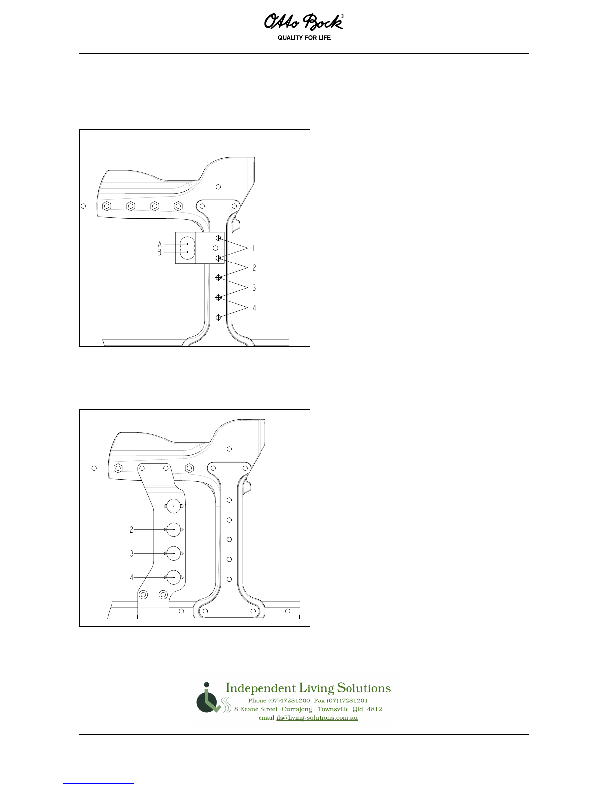
Rear wheel adapter
M1, M2, M3, M6
M4, M5
 Loading...