

Page 1
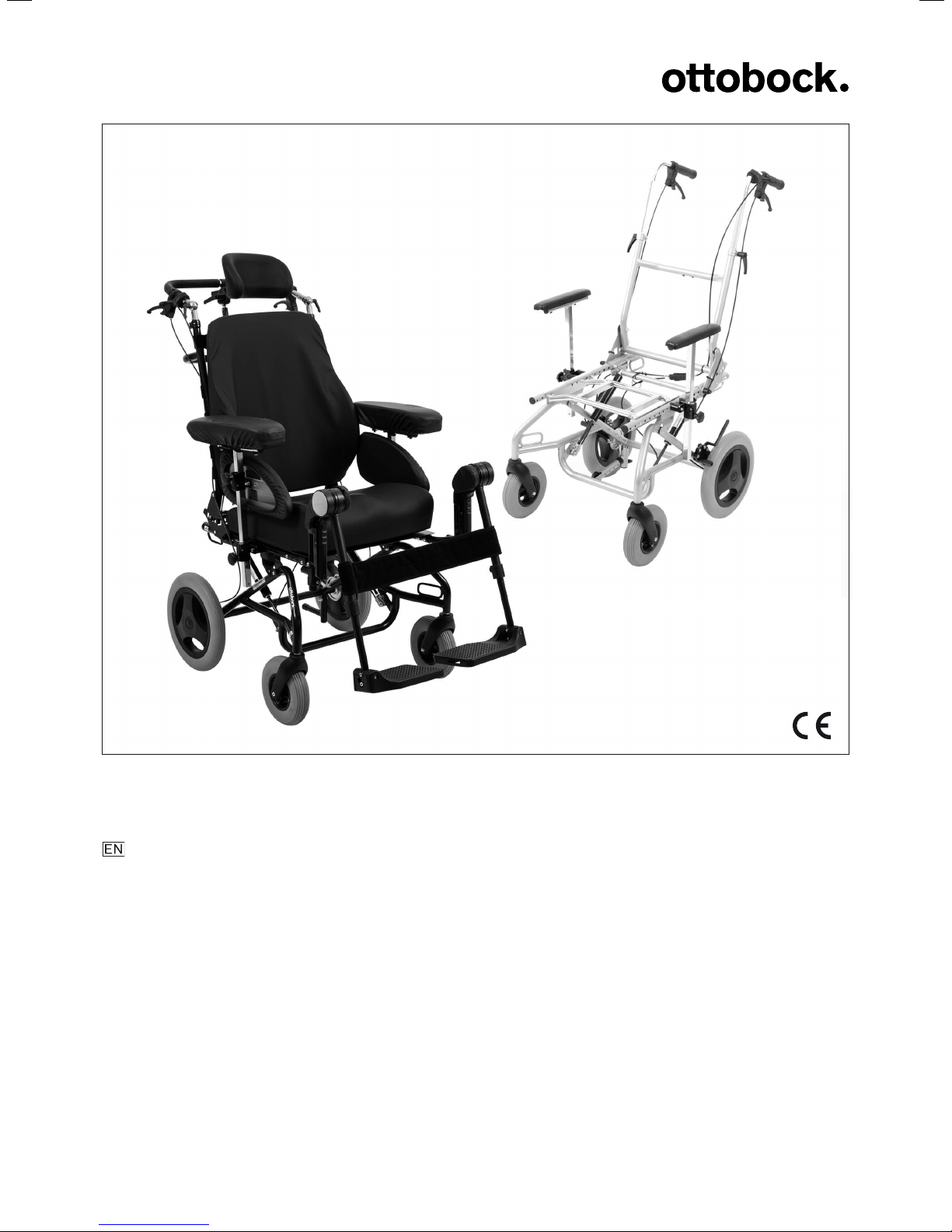
Discovery
Instructions for use (qualified personnel) ................................................................. 3
Page 2

2 Discovery
Page 3

Table of contents
Foreword1 5..............................................................................................................................................................
Intended use2 5........................................................................................................................................................
Indications for use2.1 5................................................................................................................................
Indications2.2 5...........................................................................................................................................
Contraindications2.3 5.................................................................................................................................
Qualification2.4 5.........................................................................................................................................
Safety3 6....................................................................................................................................................................
Explanation of warning symbols3.1 6..............................................................................................................
General safety instructions3.2 6.....................................................................................................................
Safety Instructions for Assembly3.3 7.............................................................................................................
Nameplate and warning labels3.4 8................................................................................................................
Signage on the product3.4.1 8.........................................................................................................................
Nameplate3.4.2 8...........................................................................................................................................
Warning labels3.4.3 9.....................................................................................................................................
Delivery4 9.................................................................................................................................................................
Scope of delivery4.1 9..................................................................................................................................
Options4.2 9...............................................................................................................................................
Discovery for Leckey KIT seat & Leckey Mygo Max (HR32040450)4.2.1 9.............................................................
Discovery with Care Chair equipment version4.2.2 9..........................................................................................
Custom fabrication version with 22"/24" drive wheels4.2.3 9................................................................................
Storage4.3 9...............................................................................................................................................
Preparation for use5 10...........................................................................................................................................
Assembly5.1 10...........................................................................................................................................
Settings6 11..............................................................................................................................................................
Prerequisites6.1 11......................................................................................................................................
Settings during preassembly6.1.1 11................................................................................................................
Adjusting the seat depth6.2 12......................................................................................................................
Adjusting the back angle6.3 12......................................................................................................................
Adaptation of the seating shell or the seating system6.4 12...............................................................................
Installing an Ottobock Shape System (option)6.4.1 12........................................................................................
Installing interface adapters for further seating systems (option)6.4.2 12...............................................................
Removing/installing a seat plate (option)6.4.3 14................................................................................................
Installing other seating systems (option)6.4.4 14.................................................................................................
Installing the back guide for seating shells (option)6.4.5 14.................................................................................
Adjusting the position of the seat bars6.5 15...................................................................................................
Checking/adjusting the seating centre of gravity6.6 15.....................................................................................
Attaching/removing the back straps (option)6.7 17...........................................................................................
Adjusting the head support (option)6.8 18.......................................................................................................
Adjusting the legrests (option)6.9 19..............................................................................................................
Adjusting the depth of the legrests/footplates6.9.1 19.........................................................................................
Adjusting the lower leg length6.9.2 20...............................................................................................................
Adjusting the support angle6.9.3 21..................................................................................................................
Adjusting the armrests (option)6.10 22.............................................................................................................
Adjusting the armrest depth with short arm support6.10.1 22.................................................................................
Adjusting the distance between the armrests with long arm support6.10.2 23..........................................................
Adjusting the armrest height and the armrest angle6.10.3 23.................................................................................
Adjusting the clothing protector (option)6.11 23................................................................................................
Belts / belt systems (option)6.12 24.................................................................................................................
Attaching belts / belt systems6.12.1 24...............................................................................................................
Adjusting the wheel adapter with 22"/24" drive wheels (custom fabrication version)6.13 25....................................
Adjusting the brakes6.14 26............................................................................................................................
Adjusting the knee lever wheel locks6.14.1 26.....................................................................................................
Adjusting the braking force of the drum brake (option)6.14.2 27.............................................................................
Table of contents
3Discovery
Page 4

Table of contents
Adjusting the anti-tipper6.15 28.......................................................................................................................
Discovery Care Chair with 12"/22"/24" rear wheels6.15.1 28................................................................................
6.15.2
Discovery Standard, Discovery for Leckey KIT seat & Leckey Mygo Max or custom fabrication versions with
12"/22"/24" rear wheels
Adjustment for 12" rear wheels 6.15.2.1 29............................................................................................................
Adjustment for 22"/24" drive wheels (custom fabrication version)6.15.2.2 29..............................................................
Delivery7 29...............................................................................................................................................................
Final inspection7.1 29..................................................................................................................................
Transport to the customer7.2 30....................................................................................................................
Handing over the product7.3 30.....................................................................................................................
Maintenance and repair8 30...................................................................................................................................
Disposal9 30.............................................................................................................................................................
Disposal information9.1 30............................................................................................................................
Information on re-use9.2 30...........................................................................................................................
Legal information10 31..............................................................................................................................................
Liability10.1 31..............................................................................................................................................
CE conformity10.2 31.....................................................................................................................................
Warranty10.3 31............................................................................................................................................
Service life10.4 31.........................................................................................................................................
Technical data11 31...................................................................................................................................................
Appendices12 33........................................................................................................................................................
Required tools12.1 33....................................................................................................................................
Torque values of the screw connections12.2 33.................................................................................................
28......................................................................................................................
4 Discovery
Page 5
Foreword
1 Foreword
INFORMATION
Last update: 2018-01-26
► Please read this document carefully before using the product.
► Follow the safety instructions to avoid injuries and damage to the product.
► Instruct the user in the proper and safe use of the product.
► Please keep this document in a safe place.
INFORMATION
► New information regarding product safety and product recalls can be obtained from the Customer Care Cen
ter (CCC) at [email protected] or from the manufacturer’s service department (see inside back cover or back
page for addresses).
► You can request this document as a PDF file from the Customer Care Center (CCC) at [email protected] or
from the manufacturer’s service department (see inside back cover or back page for addresses). It is possible
to increase the display size of the PDF document.
Initial adjustments to the product were made according to the order form. Nevertheless, fine adjustment may be
required and settings may have to be made according to the medical conditions or the user's requirements.
These instructions for use provide the information necessary for adjusting the settings. This work should be closely
coordinated with the user.
Please note the following:
• The instructions for use (qualified personnel) are intended only for qualified personnel and remain with them.
• The operation of the product and functionality of the options are described in the instructions for use (user).
These instructions for use must be given to the user.
• All users must be instructed in the use of the product by you or an attendant using the instructions for use
(user).
• The manufacturer recommends checking the product settings regularly in order to assure an optimum fit over
the long term. A review is required every six months for children and youths in particular.
• The installation and retrofitting of all optional components are generally described in the service manual.
2 Intended use
2.1 Indications for use
The Discovery mobility base for seating shells is intended exclusively for the adaptation of orthopaedic seating sys
tems (e.g.seating shells) for people who are unable to walk or have walking impediments. It can be operated
either by the user or by an attendant. The product can be used indoors and outdoors.
The Discovery mobility base for seating shells was developed especially for the adaptation of modular seating sys
tems. It is fully adjustable to provide for individual adaptation to the needs of the user.
The product may only be used with the options which are listed in the product order form.
Ottobock assumes no liability for combinations with medical devices and/or accessories from other manufacturers
not included in the modular system.
2.2 Indications
The product can be used for a disability or walking impairment, for example due to:
• Paralysis (paraplegia, tetraplegia)
• Loss of limbs (leg amputation)
• Defects or deformation of the limbs
• Joint contractures or damage
• Neurological and muscular diseases
2.3 Contraindications
Not known.
2.4 Qualification
The adjustment tasks described below are necessary for optimum adaptation to the respective seating system, and
may only be completed by qualified, authorised personnel.
5Discovery
Page 6
Safety
3 Safety
3.1 Explanation of warning symbols
WARNING
CAUTION
NOTICE
3.2 General safety instructions
WARNING
Lack of instruction
Tipping over, falling of the user due to lack of knowledge
► Instruct the user or the attendant in the proper use of the product when handing it over.
WARNING
Incorrect settings
Tipping over, falling or malposition of the user due to incorrect settings
► Adjustment and installation work may only be completed by instructed, qualified personnel.
► Only the settings described in these instructions for use may be carried out.
► Settings may only be changed within the allowable adjustment ranges; otherwise, the stability of the product
may be impaired (see this section and the "Technical data" section). If you have questions, contact the manu
facturer's service (see back cover for addresses).
► Only conduct tests in the presence of an assistant.
► Unless expressly described, you may not change any settings with a person sitting in the product.
► Secure the user against falling out during all tests.
► Before testing setting changes with the user seated, firmly tighten all screw connections.
► Check for safe function before delivering the product.
Warning regarding possible serious risks of accident or injury.
Warning regarding possible risks of accident or injury.
Warning regarding possible technical damage.
CAUTION
Use of unsuitable tools
Pinching, crushing or damaging the product due to use of unsuitable tools
► When completing the tasks, only use tools that are suitable for the conditions at the place of work and for
which safety and the protection of health are assured with proper use.
► Observe the specifications in the section "Required Tools".
NOTICE
Tipping or falling of the product
Damage to product due to lack of attachment
► When you work on the product, secure it so that it cannot tip over or fall over.
► Use a clamping fixture to secure the product whenever you work on it at a workbench.
NOTICE
Use of unsuitable packaging
Damage to the product caused by transportation using incorrect packaging
► Use only the original packaging for delivery of the product.
INFORMATION
While installing add-on drives on the product is generally not permitted, it can be reviewed by our Custom Fabric
ation department on request.
6
Discovery
Page 7
Safety
3.3 Safety Instructions for Assembly
WARNING
Use of alternative seating systems
Serious injuries to the user due to missing anti-tipper
► If the product is fitted with an alternative seating system or seating shells from other manufacturers, special
attention must be paid to static stability.
► The qualified personnel is obligated to ensure the static stability of such a combination.
► Using an anti-tipper may be required depending on the centre of gravity.
► Verify that the anti-tipper has been installed and adjusted properly.
CAUTION
Unsecured screw connections
Pinching, crushing, tipping over, falling of user due to assembly errors
► After all adjusting/readjusting work, retighten the mounting screws/nuts firmly. Observe any torque settings
which may be specified.
► Any time you loosen a screw connection with thread lock, replace it with a new screw connection with thread
lock or secure the old screw connection with medium strength thread locker (e.g.Loctite®241).
CAUTION
Improper use of self-locking nuts
Tipping, falling over of the user due to screw connections coming loose
► Always replace self-locking nuts with new self-locking nuts after disassembly.
CAUTION
Exposed pinch points
Crushing, pinching due to incorrect handling
► When folding the mobility base for seating shells out or together, only grip by the specified components.
CAUTION
Sudden extension of gas compression springs
Impacts, pinching, crushing due to incorrect handling
► The gas compression springs must be fully extended when carrying out any work (seat tilt released, seat in the
neutral horizontal position).
► Never operate the release lever for the seat tilt when screw connections are loosened or when working on the
product.
► Secure the release lever for the seat tilt during all work to avoid operating it unintentionally.
CAUTION
Incorrect air pressure
Uncontrolled driving characteristics, falling, tyre rupture due to incorrect inflation
► Maintain sufficient air pressure in pneumatic tyres. Do not exceed the permitted specifications when filling the
tyres (see Page31).
► Do not use the product with over/under-inflated or unequally inflated tyres.
► Note that a single tyre with low air pressure can lead to uncontrolled driving characteristics.
► Note that low pressure of the rear wheels / drive wheels can reduce the braking force of the knee lever wheel
lock.
CAUTION
Defective tyres
Accidents/falling due to poor traction, reduced braking force or lack of manoeuvrability
► Ensure that the tyres have sufficient tread depth.
► Ensure that the knee lever wheel lock is properly adjusted (approx. 5mm gap to the tyres, technical changes
reserved).
7Discovery
Page 8
Safety
3.4 Nameplate and warning labels
3.4.1 Signage on the product
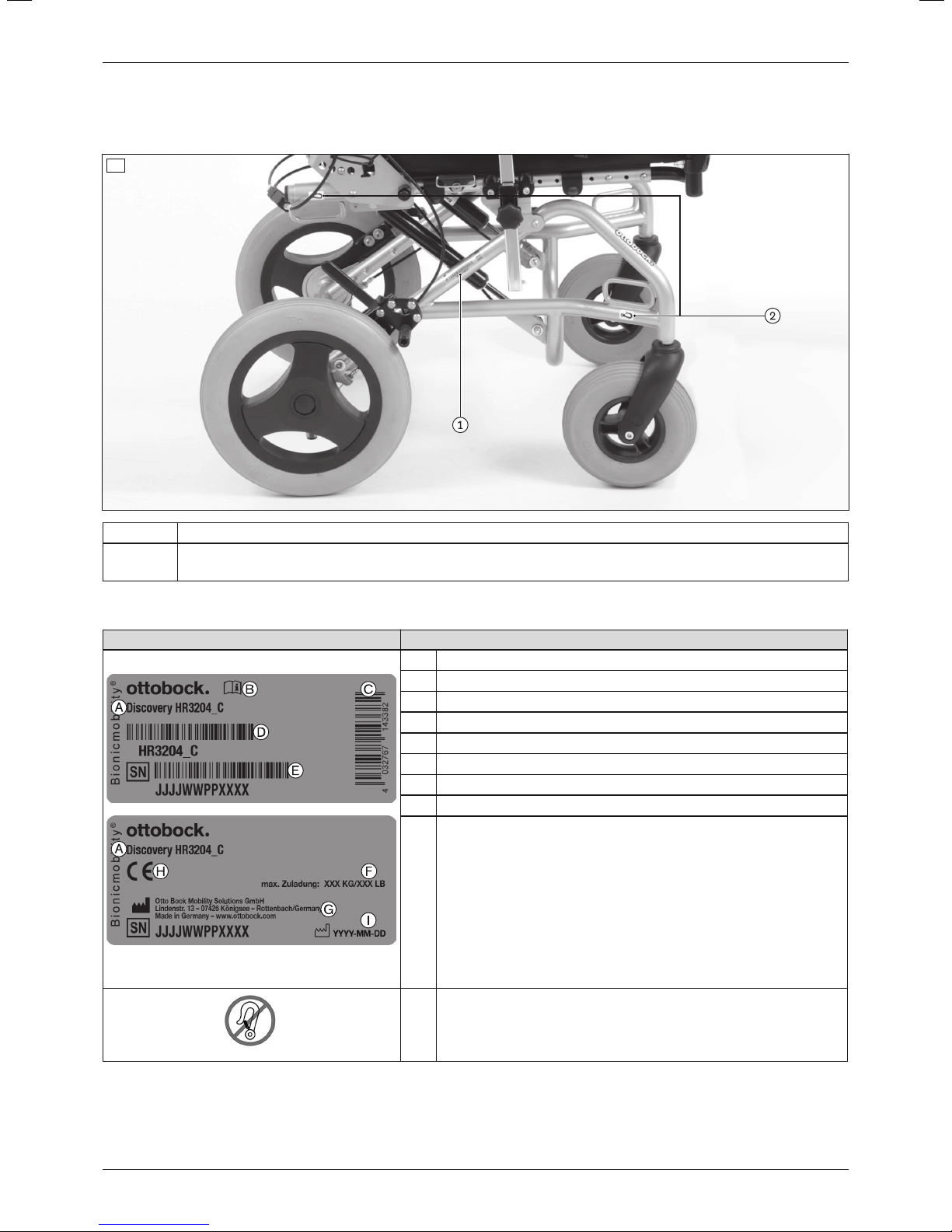
The warning signs and nameplates are attached to the product at the following mounting points:
1
1 Nameplate
2 Fixation point / anchor point to attach the product in vehicles for transporting persons with reduced
mobility
3.4.2 Nameplate
Label Meaning
A Type designation (including product reference number)
B Read the instructions for use before using the product.
C European article number (EAN)
D Product reference number
E Serial number*
F Maximum load capacity (see section "Technical data")
G Manufacturer information/address/country
H CE marking – product safety in accordance with EU directives
I Manufacturing date**
The nameplate is located on the right con
necting tube of the main frame.
If the adjacent symbol appears on the nameplate, this indic
ates the following:
The mobility base for seating shells may not be used as a seat
in vehicles for transporting persons with reduced mobility.
* JJJJ = year of manufacture; WW = week of manufacture; PP = production site; XXXX = sequential production
number
** YYYY = year of manufacture; MM = month of manufacture; DD = day of manufacture
8
Discovery
Page 9
Delivery
3.4.3 Warning labels
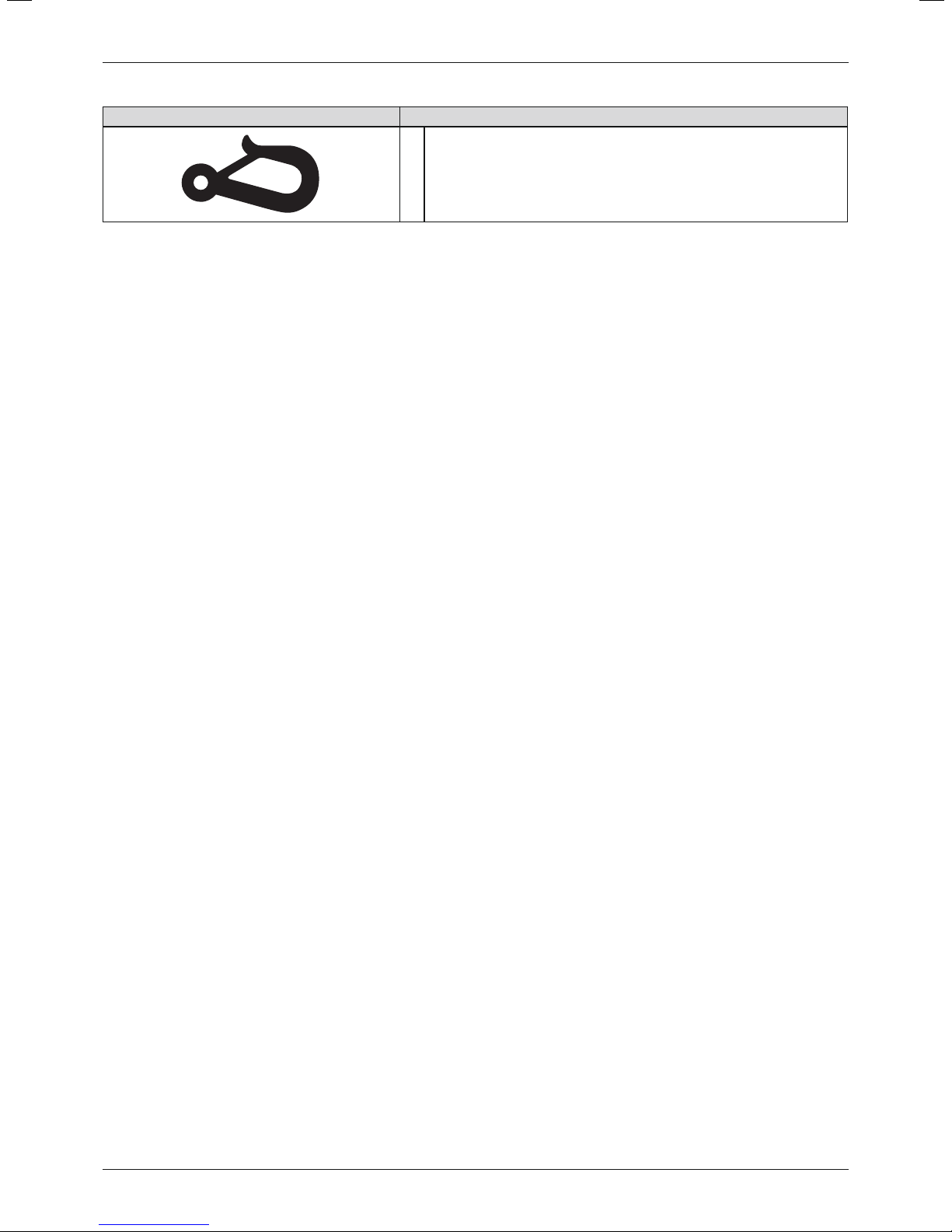
Label Meaning
Fixation point/eyebolt to attach the product in vehicles for trans
porting persons with reduced mobility
4 Delivery
4.1 Scope of delivery
The product is generally delivered fully assembled.
Only for custom fabrication models with 22"/24" drive wheels: The product is generally delivered fully
assembled and with the drive wheels removed.
The scope of delivery includes:
• Preassembled mobility base for seating shells
• 2 rear wheels / drive wheels (screwed or plug-on)
• Options according to the order
• Instructions for use (qualified personnel), instructions for use (user)
4.2 Options
The functionality and operation of the options are described in more detail in the instructions for use (user).
All of the available options/accessories are listed on the order form.
4.2.1 Discovery for Leckey KIT seat & Leckey Mygo Max (HR32040450)
The Discovery for Leckey KIT seat & Leckey Mygo Max (HR32040450) is a preconfigured version of the Discovery
mobility base for seating shells and includes the following special features and options:
• Reinforced frame with 450mm frame width
• Interface adapter for Leckey KIT seat & Mygo Max
• Push handles, long
• Knee lever wheel lock
• Anti-tipper
4.2.2 Discovery with Care Chair equipment version
The Discovery Care Chair is a configurable equipment version of the Discovery mobility base for seating shells.
Options and settings which apply only to this equipment version are specially marked in the following sections.
4.2.3 Custom fabrication version with 22"/24" drive wheels
This custom fabrication version is a customer-specific adaptation of the Discovery mobility base for seating shells
for self-propelling users carried out by Ottobock's Custom Fabrication department.
The 22"/24" drive wheels are attached to the mobility base for seating shells with a wheel adapter and quickrelease axles.
4.3 Storage
The product must be stored in a dry place. An ambient temperature between -10°C and +40°C must be main
tained.
It is not necessary to disassemble or fold up the product.
During extended storage, the knee lever wheel lock on products with PU tyres (=tubeless tyres) must be released
since tyre deformation may otherwise result.
Tyres contain chemical substances that can react with other chemical substances (such as cleaning agents, acids,
etc.).
9Discovery
Page 10
Preparation for use
5 Preparation for use
5.1 Assembly
WARNING
Overloading
Severe injuries if the product tips over due to overloading, damage to the product
► Do not exceed the maximum load capacity (see the nameplate and section "Technical data").
► Please note that certain options and add-on components will reduce the remaining load capacity.
CAUTION
Failure to verify readiness for use before putting into operation
Tipping, falling due to incorrect adjustment or installation
► Check the existing settings prior to first use.
► After each assembly, verify the proper fit of the removable wheels. The quick-release axles must be firmly
locked in the quick-release axle housings.
► In particular, verify tip resistance, easy operation of the wheels and correct brake functionality.
CAUTION
Loss of stability
Tipping, falling due to additional objects on the product
► Do not attach additional objects to the frame, cross tubes or seat.
CAUTION
Incorrect air pressure
Uncontrolled driving characteristics, falling, tyre rupture due to incorrect inflation
► Maintain sufficient air pressure in pneumatic tyres. Do not exceed the permitted specifications when filling the
tyres (see Page31).
► Do not use the product with over/under-inflated or unequally inflated tyres.
► Note that a single tyre with low air pressure can lead to uncontrolled driving characteristics.
► Note that low pressure of the rear wheels / drive wheels can reduce the braking force of the knee lever wheel
lock.
INFORMATION
In general, only metric screws are used on the product.
Exception: axle mounting of the 12" rear wheels (1/2" hexagon head screw + hexagon nut)
INFORMATION
With the combination of Allen head screw/hexagon nut, a higher torque can be transmitted using the hexagon nut
than the Allen head screw.
Please note that the Allen head screw is only intended to be held in place so it does not turn when tighten
ing/loosening the hexagon nut.
1) For plug-on drive wheels: Attach drive wheels to the drive wheel attachment device. It must not be possible to
remove the quick-release axles after releasing the push-button.
2) Optional: Slide the legrests into the holders on the front frame tube.
3) Optional: Fold down the foot supports. If necessary, insert the calf band and adjust it.
4) Prior to the adaptation of the seating shell / seating system, further settings on the mobility base for seating
shells must be adjusted as required (see Page11 ff.).
5) Adapt the seating shell / seating system to the mobility base for seating shells (see Page12).
6) Verify the stability of the assembled product.
INFORMATION: Inform the user and the attendants if the static stability is found to be less than 10°. In
this case, determine additional safety measures together with the user and attendants to ensure the
safety of the user.
10
Discovery
Page 11
Settings
6 Settings
6.1 Prerequisites
WARNING
Incorrect settings
Tipping over, falling or malposition of the user due to incorrect settings
► Adjustment and installation work may only be completed by instructed, qualified personnel.
► Only the settings described in these instructions for use may be carried out.
► Settings may only be changed within the allowable adjustment ranges; otherwise, the stability of the product
may be impaired (see this section and the "Technical data" section). If you have questions, contact the manu
facturer's service (see back cover for addresses).
► Only conduct tests in the presence of an assistant.
► Unless expressly described, you may not change any settings with a person sitting in the product.
► Secure the user against falling out during all tests.
► Before testing setting changes with the user seated, firmly tighten all screw connections.
► Check for safe function before delivering the product.
WARNING
Lack of stability against tipping
User may fall or tip over due to lack of inspection
► Changing the settings can lead to instability of the system as a whole. Verify tipping resistance after any
changes to the settings.
CAUTION
Sudden extension of gas compression springs
Impacts, pinching, crushing due to incorrect handling
► The gas compression springs must be fully extended when carrying out any work (seat tilt released, seat in the
neutral horizontal position).
► Never operate the release lever for the seat tilt when screw connections are loosened or when working on the
product.
► Secure the release lever for the seat tilt during all work to avoid operating it unintentionally.
CAUTION
Unsecured screw connections
Pinching, crushing, tipping over, falling of user due to assembly errors
► After all adjusting/readjusting work, retighten the mounting screws/nuts firmly. Observe any torque settings
which may be specified.
► Any time you loosen a screw connection with thread lock, replace it with a new screw connection with thread
lock or secure the old screw connection with medium strength thread locker (e.g.Loctite®241).
CAUTION
Improper use of self-locking nuts
Tipping, falling over of the user due to screw connections coming loose
► Always replace self-locking nuts with new self-locking nuts after disassembly.
Adjustments to match the concrete physical and mental condition of the user should always be made in the user's
presence.
All parts of the product should be cleaned thoroughly before adjustments are made.
The tools required for adjustments and maintenance tasks as well as the torque values for screw connections are
listed in the section "Appendices" (see Page33).
6.1.1 Settings during preassembly
If the seating shell / seating system has already been preassembled, the following sections can be omitted:
11Discovery
Page 12
Settings
• Section "Adjusting the seat depth" (see Page12)
• Section "Adjusting the back angle" (see Page12)
• Section "Adaptation of the seating shell / seating system" (see Page12)
6.2 Adjusting the seat depth
The seat depth can be adjusted in 4 steps by sliding the back frame on the seat frame:
1) When using a seat plate: Remove the seat plate (see Page14).
2) Loosen and remove the screw connections between the backrest attachment device and the seat bar on both
sides (see fig.2, item1).
CAUTION! Risk of pinching between freely movable frame components. Actively secure the back
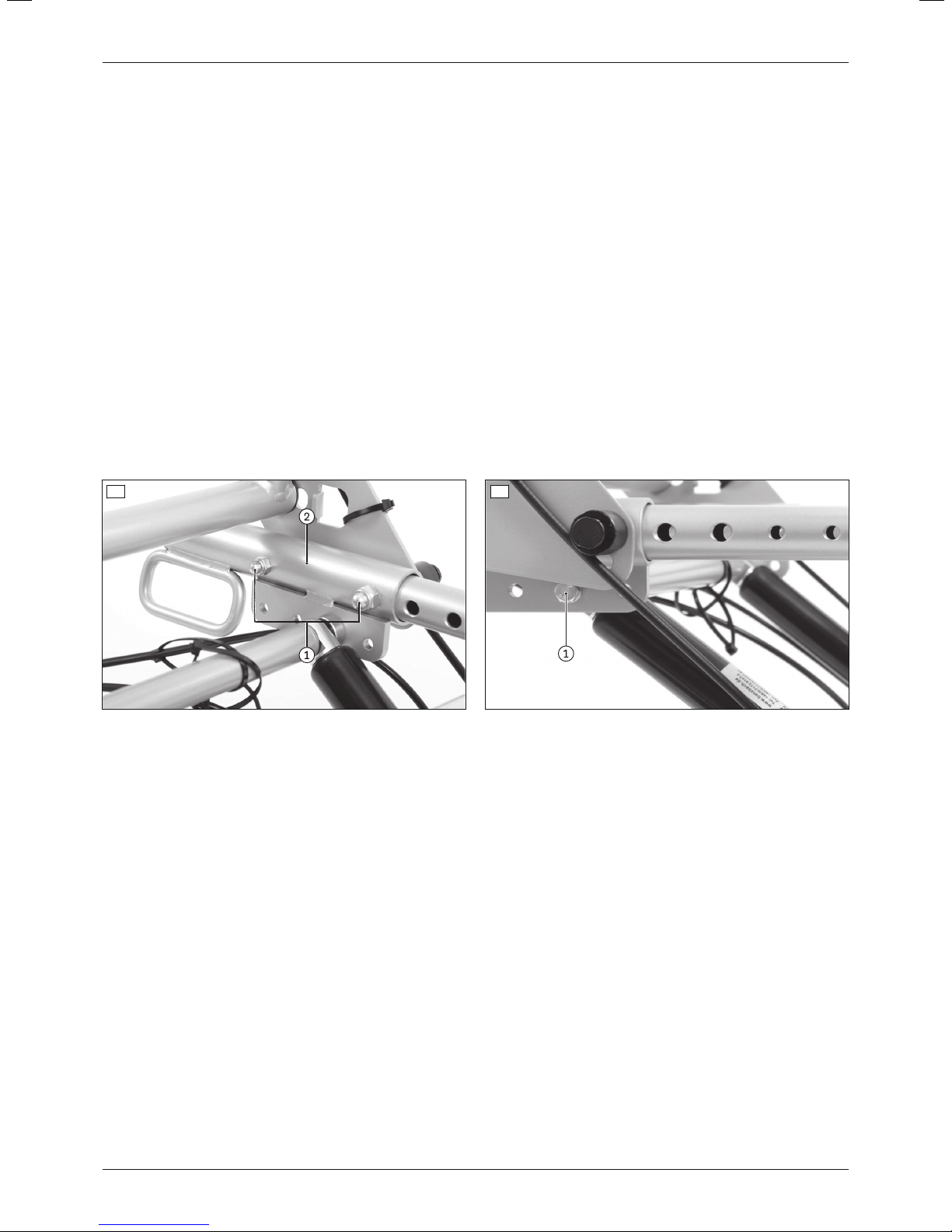
frame and the seat frame against falling.
3) Loosen and remove the screw connection between the perforated plate and gas compression spring on both
sides (see fig.3, item1).
CAUTION! Risk of pinching between freely movable gas compression springs. Actively secure the gas
compression springs against falling.
4) Slide the backrest attachment devices and the back frame to the desired seat depth (see fig.2, item2).
INFORMATION: Slide the backrest attachment devices and the position of the gas compression
springs equally. This maintains the angle setting of the seat frame.
5) Reinsert all screw connections in their original positions and firmly tighten them (see fig.2, item1; see fig.3,
item1).
6) When using a seat plate: Reinstall the seat plate (see Page14).
2 3
6.3 Adjusting the back angle
Adjusting the back angle is described in more detail in the included instructions for use (user).
6.4 Adaptation of the seating shell or the seating system
6.4.1 Installing an Ottobock Shape System (option)
This option may only be installed by Ottobock at this time.
6.4.2 Installing interface adapters for further seating systems (option)
The following interface adapters can be installed:
• Trapezoid adapter
• Parallel adapter
• Universal adapter (crossbars)
• "Shape/Moss" type
• "Leckey Mygo" type (400mm frame width required)
• "Leckey Squiggles" type (360mm frame width required)
• "Leckey KIT seat" and "Leckey Mygo Max" types (Discovery HR32040450 required)
• "Dräger" type
The removal and attachment of seating shells / seating systems on the interface adapters is described in more
detail in the included instructions for use (user).
12
Discovery
Page 13
Settings
a) Removing/installing one of the following interface adapters:
• Trapezoid adapter
• Parallel adapter
• "Dräger" type
• Leckey "Squiggles", "Mygo", "Mygo Max", "KIT seat" types
1) Remove the seating shell / seating system with the seating shell interface.
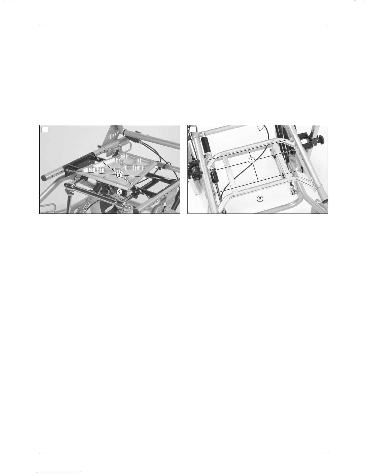
2) Loosen and remove the screw connections between the interface adapter and seat bars (see fig.4, item1; see
fig.5, item1).
3) Remove/replace the interface adapter (see fig.4, item2; see fig.5, item2).
4) Insert the screw connections into the appropriate slots between the interface adapter and seat bars and firmly
tighten them to a torque of 10Nm (see fig.4, item1; see fig.5, item1).
5) Remount the seating shell / seating system with the seating shell interface.
4 5
b) Removing/installing one of the following interface adapters:
• Universal adapter (crossbars)
• "Shape/Moss" type
1) Remove the seating shell / seating system with the seating shell interface.
2) Loosen and remove the screw connections between the backrest attachment device and the seat bar on both
sides (see fig.6, item1).
CAUTION! Risk of pinching between freely movable frame components. Actively secure the back
frame and the seat frame against falling.
INFORMATION: Mark / take note of the original seat depth and position of the backrest attachment
devices.
3) Loosen and remove the screw connection between the perforated plate and gas compression spring on both
sides (see fig.7, item1).
CAUTION! Risk of pinching between freely movable gas compression springs. Actively secure the gas
compression springs against falling.
4) Slide the backrest attachment devices down and off the seat bars and set them safely aside with the back
frame (see fig.6, item2).
5) Loosen and remove the screw connections between the interface adapter and seat bars.
6) Slide the interface adapter down and off the seat bars / replace it.
7) Insert the screw connections between the interface adapter and seat bars and firmly tighten them to a torque of
10Nm.
8) Slide the back frame together with the backrest attachment devices onto the seat bars (see fig.6, item2).
INFORMATION: Return the backrest attachment devices and the gas compression springs to their ori
ginal position.
9) Reinsert all screw connections in their original positions and firmly tighten them to a torque of 10Nm (see
fig.6, item1; see fig.7, item2).
10) Remount the seating shell / seating system with the seating shell interface.
13Discovery
Page 14
Settings
6 7
6.4.3 Removing/installing a seat plate (option)
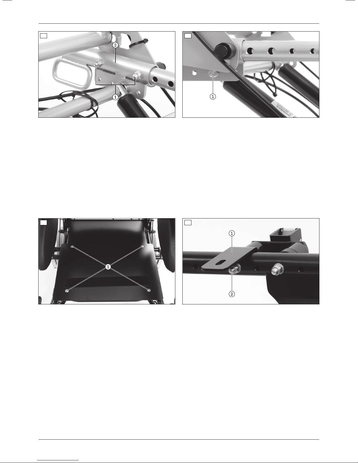
For removal/installation within the scope of adjustments or retrofitting a new seat plate, complete the following
steps:
1) Loosen and remove all screw connections between the seat plate and seat plate supports (see fig.8, item1).
2) Remove/replace the seat plate.
3) If necessary: Remove/replace the seat plate supports (see fig.9, item1). Do this by loosening and removing
the screw connections on the seat plate supports (see fig.9, item2).
4) Install the seat plate supports on the seat bars (see fig.9, item1). Do this by inserting the screw connections
into the seat plate supports and firmly tightening them to a torque of 10Nm (see fig.9, item2).
5) Position the seat plate on the seat plate supports.
6) Insert all screw connections between the seat plate and the seat plate supports and firmly tighten them to a
torque of 10Nm (see fig.8, item1).
8 9
6.4.4 Installing other seating systems (option)
In principle, it is possible to install third-party seating systems on the product. In this case, liability rests with the
qualified personnel that completed the installation.
Installation by Ottobock Custom Fabrication is possible with a separate order.
The manufacturer assumes no liability for combinations with seating systems that have not been approved by the
manufacturer.
6.4.5 Installing the back guide for seating shells (option)
The back guide for seating shells is attached to the cross tube of the back frame. The guide plate is attached to the
back of the seating shell using 4 screws (see fig.10, item1) and connected to the back guide:
1) Loosen the clamping screw on the back guide (see fig.10, item2).
2) Insert the clamping plate into the guide plate, narrow side first (see fig.10, item3).
3) Turn the clamping plate 90° so that it engages sideways in the guide plate. (see fig.10, item3).
4) Firmly tighten the clamping screw on the back guide (see fig.10, item2).
14
Discovery
Page 15
Settings
10
6.5 Adjusting the position of the seat bars
The seat bars can be moved to an anterior or posterior position, e.g.to shift the centre of gravity or to provide more
space for the legrests:
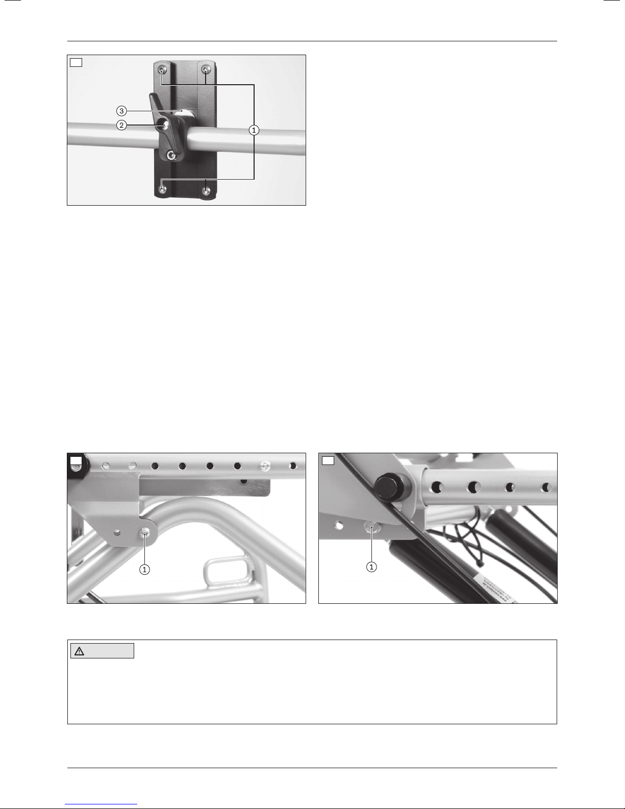
1) Loosen and remove the screw connection on the pivot point of the seat tilt (see fig.11, item1).
CAUTION! Risk of pinching between freely movable frame components. Actively secure the seat frame
against falling.
2) Move the seat bars to the desired position.
3) Reinsert the screw connections at the pivot point for the seat tilt on both sides and firmly tighten them to a
torque of 10Nm (see fig.11, item1).
4) Loosen and remove the screw connection between the perforated plate and gas compression spring on both
sides (see fig.12, item1).
CAUTION! Risk of pinching between freely movable gas compression springs. Actively secure the gas
compression springs against falling.
5) Move the gas compression springs along the perforated plate according to the position of the seat bars.
INFORMATION: Slide the position of the seat bars and the position of the gas compression springs
equally. This maintains the angle setting of the seat frame. If the raster provided by the perforated
plate is insufficient, carry out the adjustment according to the seat depth (see Page12).
6) Reinsert all screw connections and firmly tighten them to a torque of 10Nm (see fig.12, item1).
11 12
6.6 Checking/adjusting the seating centre of gravity
CAUTION
Improper adjustment of the seating centre of gravity
Tipping, falling from the seating shell / seating system due to incorrect adjustment
► Avoid extreme settings that could lead to tipping when adjusting the seat angle.
► For transfemoral amputees, shift the seating centre of gravity forward. This improves the stability of the mobil
ity base for seating shells.
Checking the seating centre of gravity is required in order to ensure that the seat angle can be adjusted easily
when the user is seated.
15Discovery
Page 16
Settings
In principle, the centre of gravity adjustment has the following effects:
Seating centre of gravity Effect
Too far in front of the pivot point Seat tilts far forward when it is unlocked;
high holding forces required during seat adjustment
Too far behind the pivot point Seat tilts far backward when it is unlocked;
high holding forces required during seat adjustment
Setting recommendations
The seating centre of gravity should be individually adjusted according to the clinical picture.
The qualified personnel has to decide whether it is better that the seat swings forward or backward when no hold
ing force is applied while the locking mechanism is released. If possible, the attendant who will be using the mobil
ity base for seating shells should be consulted here.
Setting the seating centre of gravity when using an interface adapter
The seating centre of gravity can be set by releasing the interface adapter and sliding it along the seat bars:
1) If necessary: Remove the seating shell interface with the seating shell / seating system if these make it difficult
to release and slide the interface adapter (see Page12).
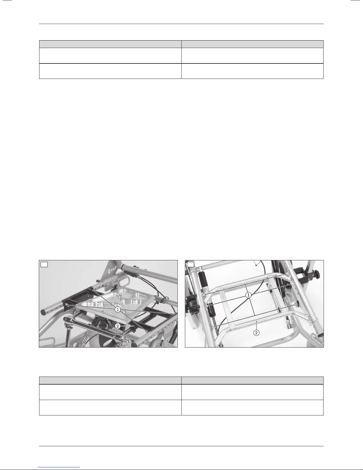
2) Loosen and remove the screw connections between the interface adapter and seat bars (see fig.13, item1;
see fig.14, item1).
3) Slide the interface adapter along the seat bars to the assumed seating centre of gravity (see fig.13, item2; see
fig.14, item2).
4) Insert the screw connections into the appropriate slots between the interface adapter and seat bars and firmly
tighten them to a torque of 10Nm (see fig.13, item1; see fig.14, item1).
5) Mount the seating shell interface with the seating shell / seating system on the interface adapter.
6) Conduct a functional test of the seat tilt and locking mechanism:
→ Tilt the seat and lock it at various positions along the entire adjustment range.
→ Ensure that the seat tilt can move freely and the locking mechanism functions securely. The seat angle must
not be adjustable after letting go of the release lever.
7) Test the seating centre of gravity setting:
→ Sit the user in the seat with the help of an assistant.
→ Tilt the seat and hold it in position. Only low holding forces should be required for tilting.
13 14
Adjusting the seating centre of gravity
If the results are not satisfactory, the setting has to be readjusted without the user in the seat, as follows:
Problem Solution
Seat tilts far forward when it is unlocked;
Slide the seat and interface adapter back
high holding forces required during seat adjustment
Seat tilts far backward when it is unlocked;
Slide the seat and interface adapter forward
high holding forces required during seat adjustment
16
Discovery
Page 17
Settings
INFORMATION
The adjustment range for the seating centre of gravity can be further expanded by adjusting the seat bar position
(see Page15).
6.7 Attaching/removing the back straps (option)
The back straps can be removed for cleaning or to replace them.
Adjusting the back straps when the user is seated is described in more detail in the included instructions for use
(user).
Attaching the back straps
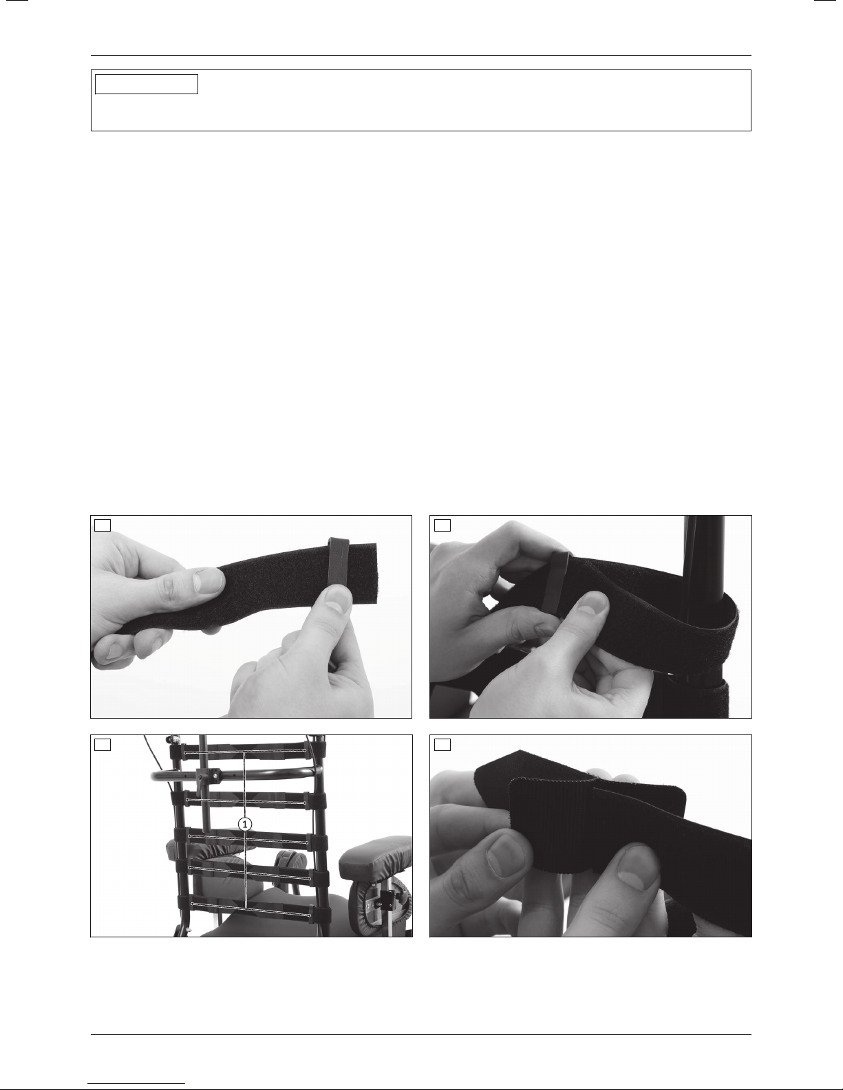
1) Guide both ends of the back straps through a plastic clamp (see fig.15).
2) Place the free ends of the back straps around the back tubes and guide them through the plastic clamp again.
Fix exposed Bowden cables as you do so if possible (see fig.16).
CAUTION! Loss of functionality of the drum brakes due to over-tightened Bowden cables. Release the
Bowden cables at the upper back straps. Only fix Bowden cables if this does not tighten them further
(see fig.17).
3) Place the Y hook-and-loop buckles around both ends of the back straps and fasten them (see fig.18).
4) Fasten one end of each of the back straps (see fig.19, item1).
5) Affix a double-side hook-and-loop strip in the same position on each of the back straps (see fig.20).
6) Pre-tension the back straps according to the needs of the user and fasten the loosen end of the back straps
(see fig.19, item2).
INFORMATION: The two ends of the back straps should not overlap. If necessary, shorten the back
straps (without Y hook-and-loop buckles) until they can no longer overlap.
7) Slide the plastic clamps on the back straps as close as possible to the back tubes (see fig.17, item1).
8) Position the back padding on the back straps at the desired height. Secure the back padding against sliding by
pressing it onto all of the double sided hook-and-loop strips on the back straps.
15 16
17 18
17Discovery
Page 18
Settings
19 20
Removing the back straps
1) Carefully pull the back padding off the back straps.
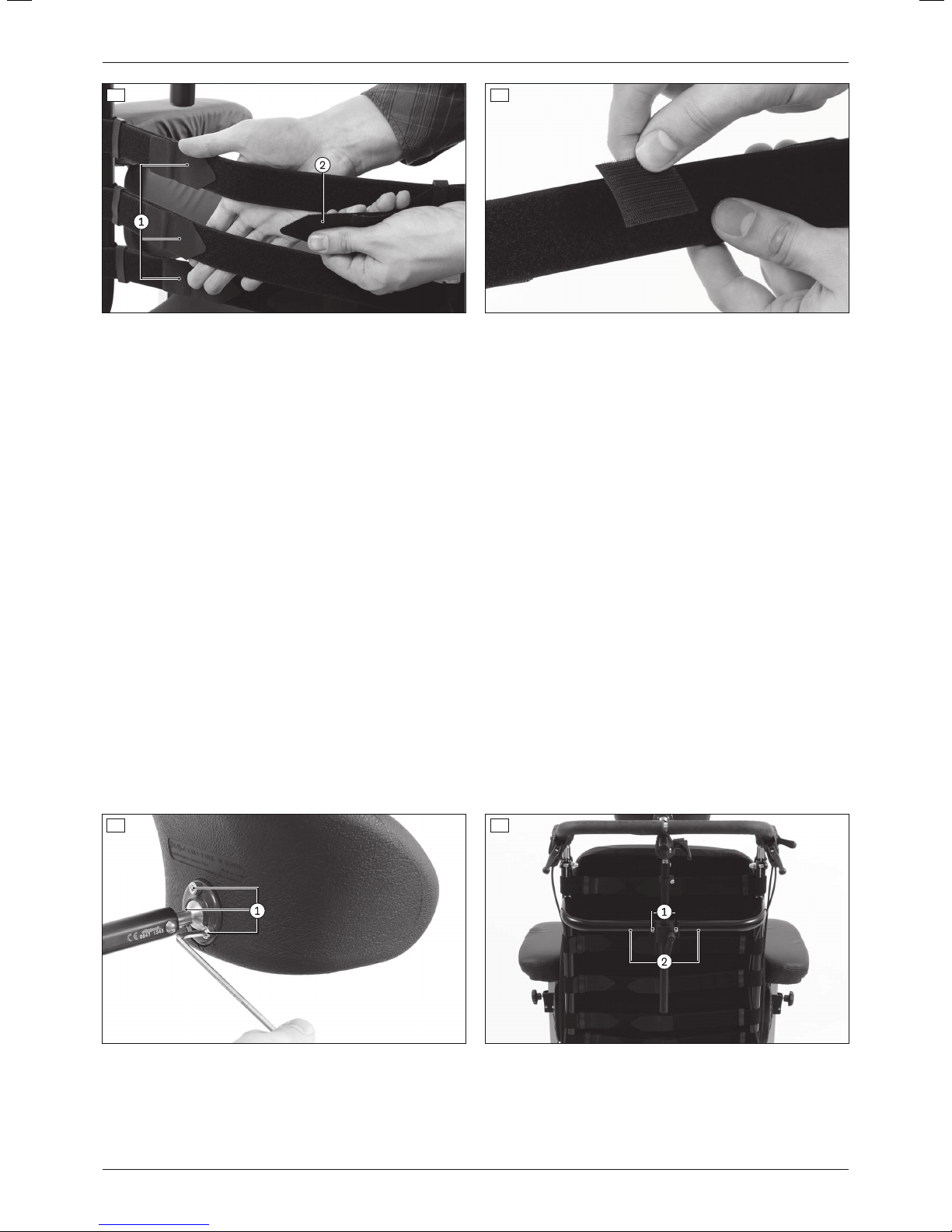
2) If necessary: Pull the double sided hook-and-loop strips off the back straps (see fig.20).
3) Open the hook-and-loop fasteners on both ends of the back straps (see fig.19, item1).
4) Open and remove the Y hook-and-loop buckles on both ends of the back straps (see fig.18).
5) Pull the free ends of the back straps out of the plastic clamps (see fig.16).
6) Pull the plastic clamps off the back straps (see fig.15).
6.8 Adjusting the head support (option)
Adjusting the height and position of the head support is described in more detail in the enclosed instructions for
use (user).
The following adjustments can also be made to the head support:
Adjusting the angle and position of the head support on the ball joint
1) Loosen the screw connections on the ball joint of the head support (see fig.21, item1).
2) Swivel the head support to the desired position.
3) Firmly tighten all screw connections on the ball joint (see fig.21, item1).
Shifting the head support sideways on the cross tube of the back frame
1) Loosen and remove the screw connections between the head support holder and the cross tube of the back
frame (see fig.22, item1).
2) Slide the head support and holder along the cross tube of the back frame to the desired position (see fig.22,
item2).
3) Insert the screw connections into the appropriate slots between the head support holder and the cross tube of
the back frame and firmly tighten them (see fig.22, item1).
21 22
18
Discovery
Page 19
Settings
6.9 Adjusting the legrests (option)
CAUTION
Improper adjustment of the legrests/footplates
Tipping over, falling due to user error
► After changing the legrest/footplate settings, verify that the legrests/footplates do not collide with the caster
wheels at any of the seat tilt settings (seat angle adjustment).
► The distance between the legrest/footplate and the caster wheel must be at least 25mm.
The footplates are the supporting surfaces for the feet.
Their distance from the seat bottom influences sitting stability. The height adjustment acts on the pelvis and ischial
bones.
The angle of the footplates should permit a comfortable ankle position.
6.9.1 Adjusting the depth of the legrests/footplates
a) Adjusting the depth of the following legrests:
• Single-panel
• Segmented (aluminium/plastic)
• Segmented for short lower leg length (aluminium)
The depth of the legrest can be adjusted using the perforated holes in the seat bars.
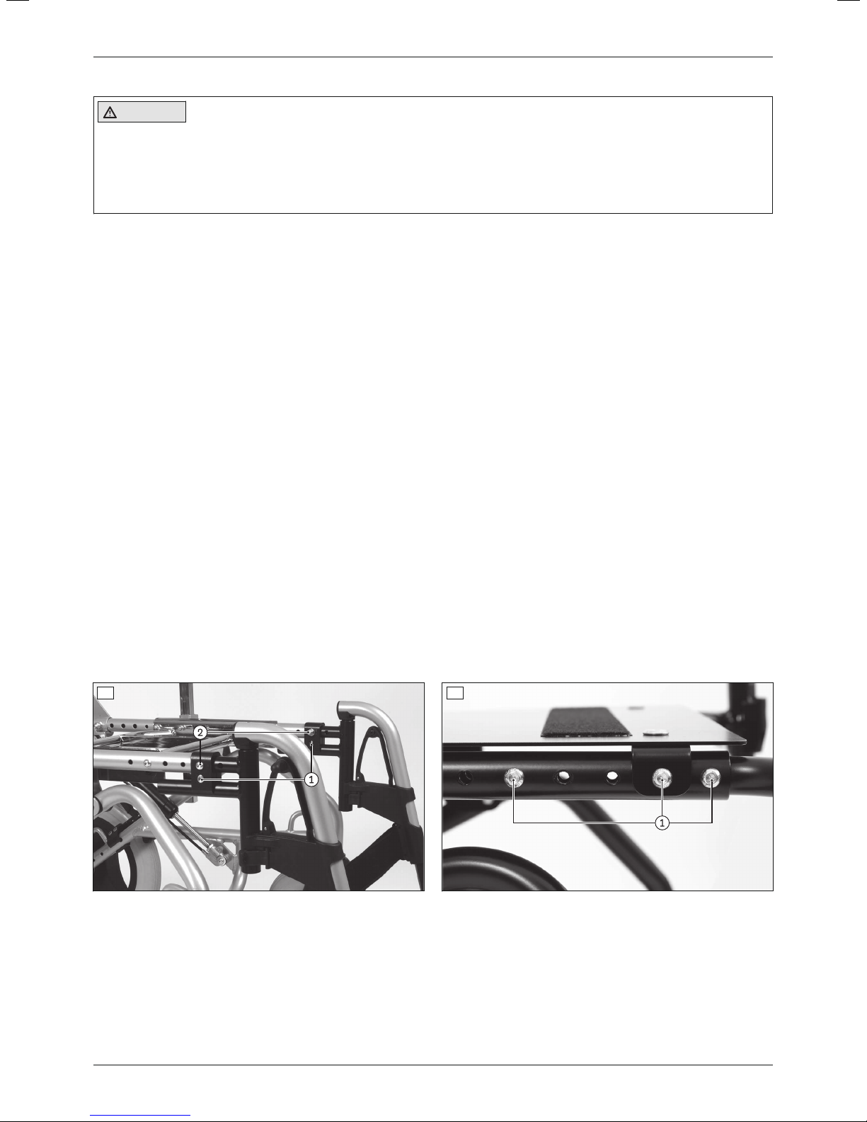
1) Loosen the lower screw connection of the legrest fixture on both sides (see fig.23, item1).
2) Loosen and remove the upper screw connection of the legrest fixture on both sides (see fig.23, item2).
3) Slide the legrest and legrest fixture to the desired depth.
4) Insert the screw connections into the appropriate slots between the seat bar and legrest fixture and firmly tight
en them (see fig.23, item1/2).
b) Adjusting the depth of the following legrests:
• Elevating with ratchet joint (aluminium)
• Elevating, segmented with calf pad (plastic)
• Elevating, segmented with calf band (plastic)
The depth of the legrest can be adjusted using the perforated holes in the seat bars.
1) Loosen and remove the screw connections on the legrest fixture (see fig.24, item1).
2) Slide the legrest and legrest fixture to the desired depth.
3) Insert the screw connections into the appropriate slots between the seat bar and legrest fixture and firmly tight
en them (see fig.24, item1).
23 24
c) Adjusting the depth of the following legrests:
• With single-panel footplate for seating shell interface (steel)
The legrest is mounted on the seating shell interface. The depth of the legrest can be continuously adjusted on the
side attachments of the seating shell interface.
1) Loosen the screw connections on both sides between the seating shell interface and the legrest bars (see
fig.25, item1).
2) Slide the legrest and the bars to the desired depth.
19Discovery
Page 20
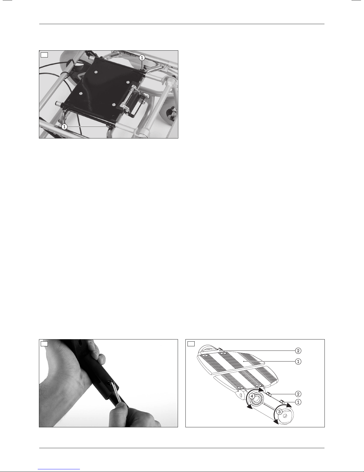
Settings
3) Firmly tighten the screw connections on the seating shell interface to a torque of 1.5Nm (see fig.25, item1).
4) Check that the legrest is securely mounted.
25
6.9.2 Adjusting the lower leg length
The required footplate position depends on the lower leg length of the user and the thickness of the seat cushion /
seating shell / seating system that is used.
a) Adjusting the lower leg length of the following legrests:
• Single-panel
• Segmented (aluminium/plastic)
• Segmented for short lower leg length (aluminium)
• Elevating with ratchet joint (aluminium)
• Elevating, segmented with calf pad (plastic)
• Elevating, segmented with calf band (plastic)
1) Loosen the lower clamping screw on both guide tubes (see fig.26).
2) Adjust the lower leg length (continuously adjustable). The footplate mounting bars must remain inserted in the
guide tube of the legrest holder to a depth of at least 40mm; otherwise, they can slide out of the guide tube.
INFORMATION: Verify sufficient ground clearance.
3) Slide the legrest and legrest fixture to the desired depth.
4) Firmly tighten the clamping screw to a torque of 10Nm (see fig.26).
Additional adjustment for short lower leg length
The lower leg length of the "Segmented for short lower leg length" legrest can be further adjusted using a slotted
hole plate.
1) Loosen the clamping screws (see fig.27, item1/2).
2) Swing the footplate to the desired height and the desired angle (see fig.27).
INFORMATION: Verify sufficient ground clearance.
3) Slide the legrest and legrest fixture to the desired depth.
4) Firmly tighten the clamping screws (see fig.27, item1/2).
26 27
20
Discovery
Page 21
Settings
b) Adjusting the lower leg length of the following legrests:
• With single-panel footplate for seating shell interface (steel)
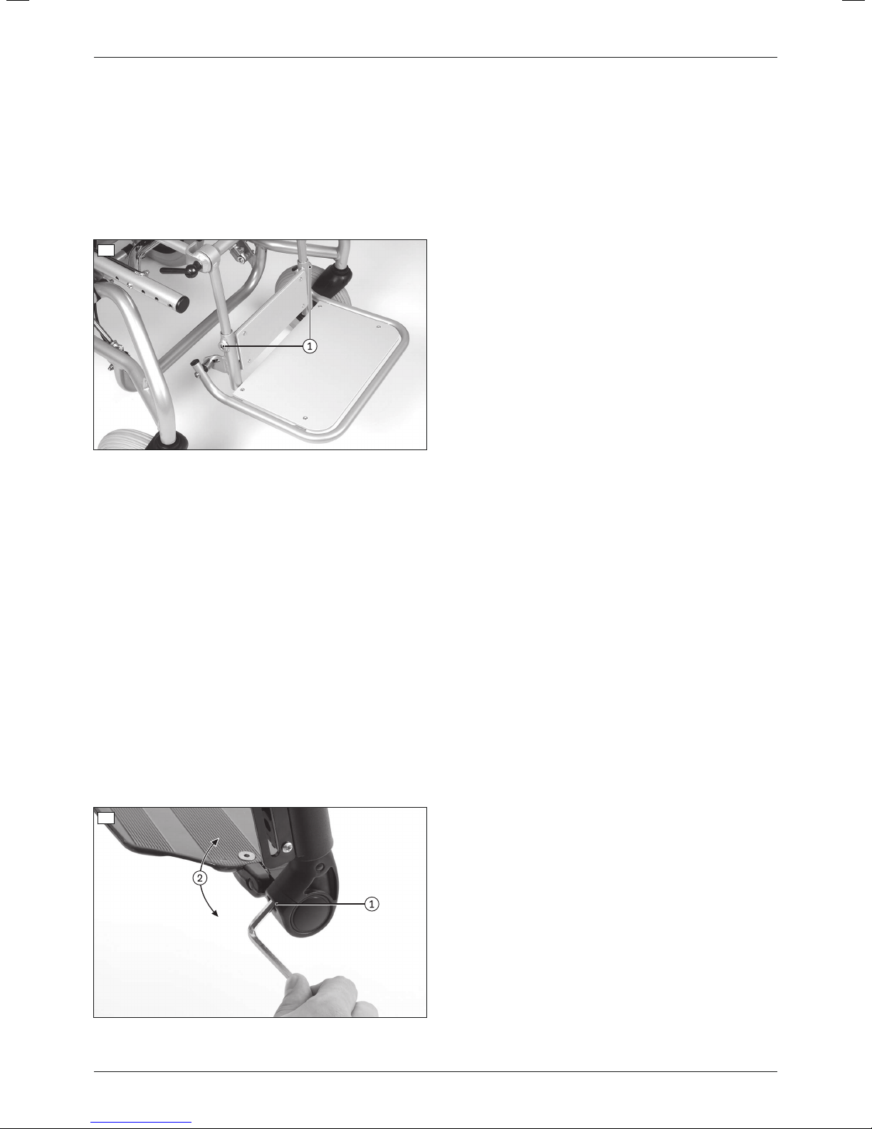
1) Loosen the clamping screws on both mounting bars (see fig.28, item1).
2) Adjust the lower leg length (continuously adjustable). The guide tubes for the footplate must remain slid onto
the mounting bars of the legrest by at least 40mm, as they could otherwise slide down and off the mounting
bars.
INFORMATION: Verify sufficient ground clearance.
3) Firmly tighten the clamping screws on both mounting bars to a torque of 1.5Nm (see fig.28, item1).
4) Check that the legrest is securely mounted.
28
6.9.3 Adjusting the support angle
The footplate angle setting should be chosen so that the ankle is in a relaxed, comfortable position.
a) Adjusting the support angle of the following legrests:
• Segmented (aluminium)
• Segmented for short lower leg length (aluminium)
• Elevating with ratchet joint (aluminium)
1) Loosen the clamping screw on the joint of the footplate (see fig.29, item1).
2) Set the desired footplate angle (see fig.29, item2).
3) Firmly tighten the clamping screw on the joint of the footplate to a torque of 10Nm (see fig.29, item1).
b) Adjusting the support angle of the following legrest:
• Single-panel
1) Loosen the clamping screw on the left and right joint of the footplate (see fig.29, item1).
2) Set the desired footplate angle (see fig.29).
INFORMATION: Set the same angle on the left and right joint so that the footplate is correctly posi
tioned.
3) Firmly tighten the clamping screw on the left and right joint of the footplate to a torque of 10Nm (see fig.29,
item1).
29
21Discovery
Page 22
Settings
c) Adjusting the support angle of the following legrests:
• Segmented (plastic)
• Elevating, segmented with calf pad (plastic)
• Elevating, segmented with calf band (plastic)
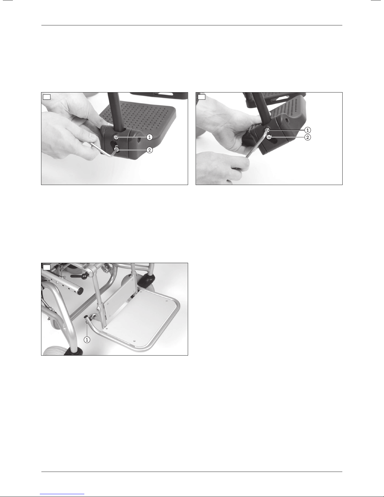
1) Loosen the screw connections on the mounting for adjusting the footplate angle (see fig.30, item1/2).
2) Set the desired footplate angle (see fig.31).
3) Firmly tighten the screw connections to a torque of 6Nm (see fig.31, item1/2).
30 31
d) Adjusting the support angle of the following legrest:
• With single-panel footplate for seating shell interface (steel)
1) Loosen the clamping screws on the left and right joint of the footplate (see fig.32, item1).
2) Set the desired footplate angle. Slide the clamping screws evenly in the left and right slotted hole without tilt
ing.
3) Firmly tighten the clamping screws on the left and right joint of the footplate (see fig.32, item1).
INFORMATION: Sufficiently tighten the clamping screws so that the footplate remains securely posi
tioned even when flipped up.
32
6.10 Adjusting the armrests (option)
6.10.1 Adjusting the armrest depth with short arm support
The depth of the armrests with short arm support can be adjusted.
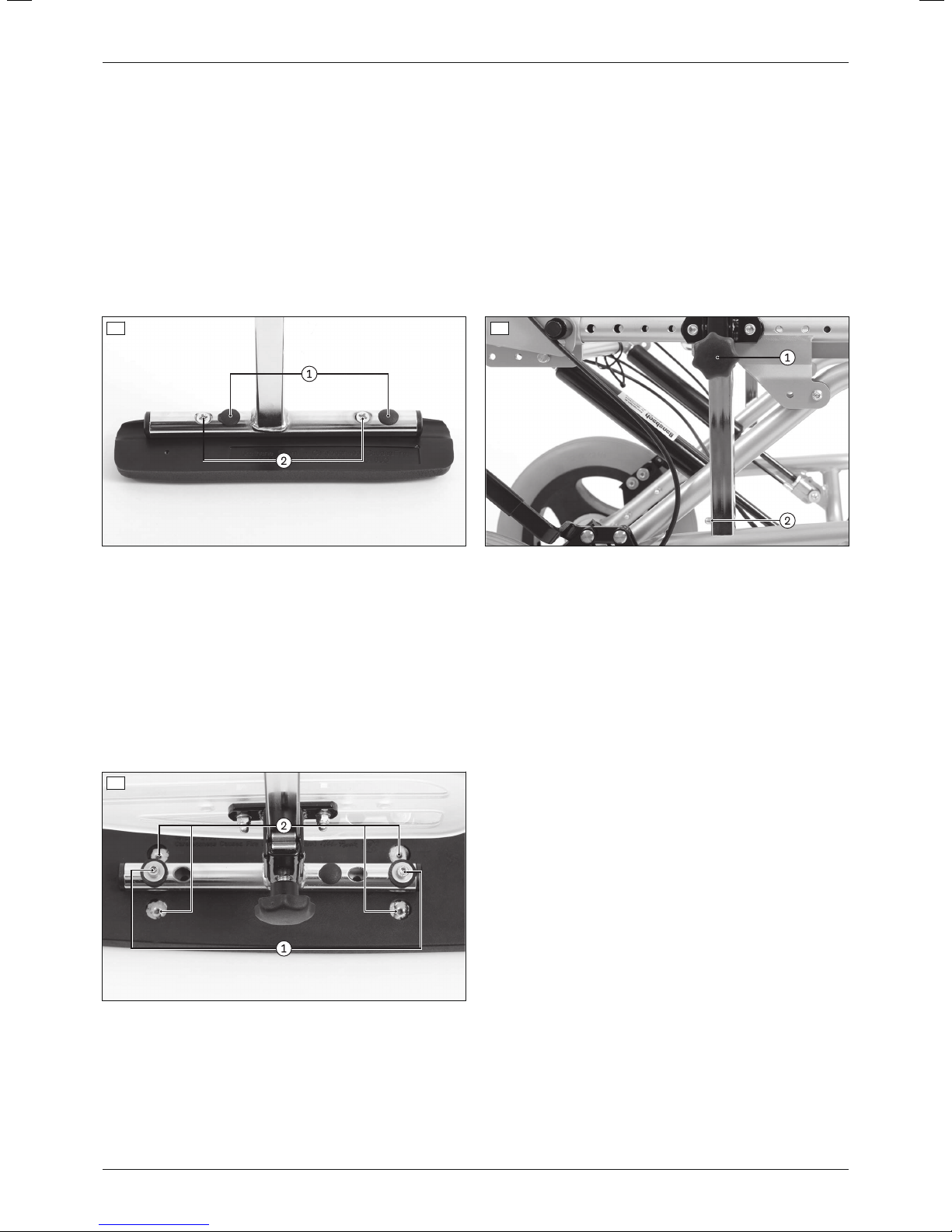
1) Remove the cover caps on the bottom of the arm support (see fig.33, item1).
2) Loosen and remove the screw connections on the bottom of the arm support (see fig.33, item2).
3) Slide the arm support along the connection tube to the desired position.
INFORMATION: Shift the left and right arm supports to the same depth.
4) Insert the screw connections into the appropriate holes on the bottom of the arm support and carefully tighten
them.
5) Firmly push the cover caps into the open holes on the bottom of the arm support.
22
Discovery
Page 23
Settings
Extended armrest depth
The armrest with short arm support can be rotated to expand the adjustment range for the armrest depth.
1) Loosen the clamping screw on the armrest (see fig.34, item1).
2) Press the tripod spring on the armrest (see fig.34, item2) and pull the armrest out of the armrest holder.
3) Rotate the armrest 180°.
INFORMATION: As you do so, swap the left and right armrests so that the arm supports and the
clamping levers for the angle adjustment (optional) are always facing outwards.
4) Press the tripod spring on the armrest (see fig.34, item2) and insert the armrest into the armrest holder from
above.
INFORMATION: Slide the armrest at least far enough in until the tripod spring audibly engages and
the armrest locks.
5) Firmly tighten the clamping screw on the armrest (see fig.34, item1).
33 34
6.10.2 Adjusting the distance between the armrests with long arm support
The distance between the armrests with long arm support can be adjusted. This can be done by moving the arm
supports inwards or outwards.
1) Loosen and remove the screw connections on the bottom of the arm support (see fig.35, item1).
2) Move the arm support to the desired position on the connection tube.
INFORMATION: Move the left and right arm supports evenly in or out.
INFORMATION: The arm support must not be rotated. Align the narrow side of the armrest to the front
according to the original position.
3) Insert the screw connections into the appropriate holes on the bottom of the arm support and carefully tighten
them (see fig.35, item2).
35
6.10.3 Adjusting the armrest height and the armrest angle
Adjusting the armrest height and the armrest angle is described in more detail in the included instructions for use
(user).
6.11 Adjusting the clothing protector (option)
The height of the clothing protector can be adjusted. Adjusting the height and position of the clothing protector is
described in more detail in the enclosed instructions for use (user).
23Discovery
Page 24
60°
Settings
6.12 Belts / belt systems (option)
CAUTION
Incorrect approach to the adjustment process
Injuries, malpositions, illness of the user due to adjustment errors
► The belt system may only be installed by qualified personnel.
► The qualified personnel is responsible for individual positioning and fitting of the belt system.
► Excessively tight adjustment of the belt system may lead to unnecessary pain or illness of the user.
► Adjusting the belt system too loosely can cause the user to slide into a dangerous position. In addition, the
fastening snaps could open unintentionally if they slide against hard parts of clothing (e.g. buttons).
► For proper installation and adjustment, follow the instructions for use included with the product.
CAUTION
Lack of instruction
Injuries, malpositions, illness of the user due to information errors
► The qualified personnel is responsible for making sure that the user and/or attendant/nursing staff has under
stood the proper adjustment, use, maintenance and care of the belt system.
► In particular, ensure that the user and/or attendant/nursing staff knows how to quickly loosen and open the
product to avoid delays in case of emergency.
6.12.1 Attaching belts / belt systems
INFORMATION
Observe the instructions for use and the safety information for the respective products regarding the installation
and safe use of the belts and positioning systems.
Lap belt, standard
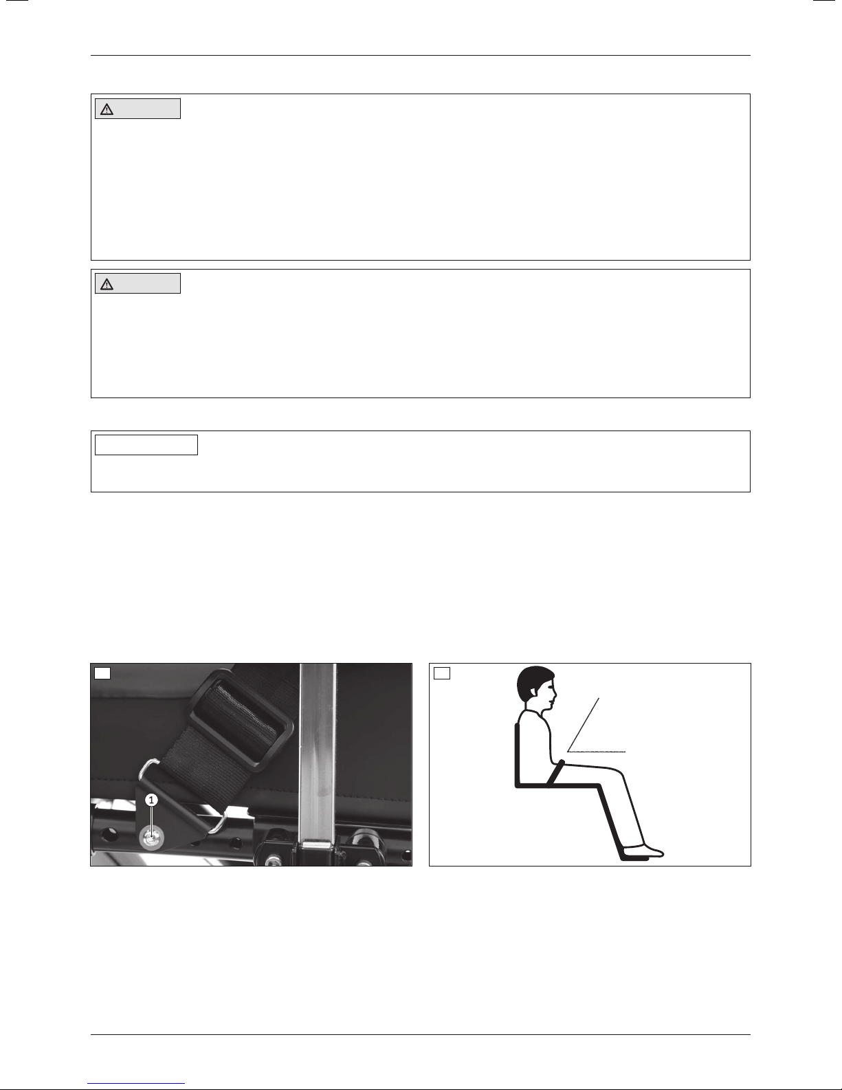
1) Screw the anchor points of the lap belt directly to the seat bars of the seat frame (see fig.36, item1).
INFORMATION: Select the holes on the seat bars such that the lap belt can be applied at an angle of
approx. 60° to the seat bottom (see fig.37).
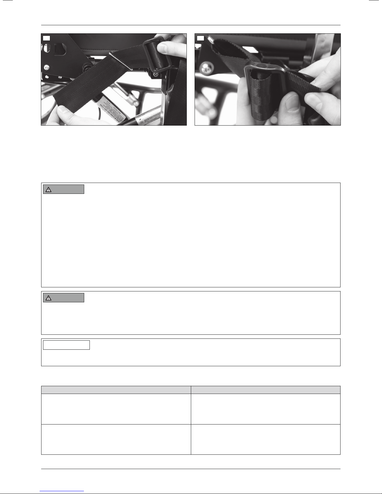
2) Guide the lap belt from the inside through the plastic eyelet and the anchor point (see fig.38).
3) Guide the lap belt through the plastic eyelet from the inside again and pull it tight (see fig.39).
INFORMATION: The free end of the lap belt must be pulled through the anchor point at least 100mm.
Secure or shorten excessively long ends of the lap belt so that these do not drag on the ground or get
caught in the wheels.
36
37
24
Discovery
Page 25
Settings
38 39
Lap belt, padded
The lap belt is delivered with a mounting kit for the seat bars.
All information on installing the anchor points and routing the lap belt are included in the instructions for use for the
lap belt and the mounting kit.
6.13 Adjusting the wheel adapter with 22"/24" drive wheels (custom fabrication version)
WARNING
Incorrectly adjusted wheelbase
Tipping over, falling of the user due to incorrect adjustment
► Only adjust the wheel adapter after completing the adjustments described above.
► Maximum stability is achieved when the frame is set in the lowest position and the rear wheels are set in the
rearmost position. Deviations from this setting reduce the stability of the mobility base for seating shells.
► Avoid extreme settings that could lead to tipping when adjusting the seat angle.
► Please note that with the rear wheel in a more forward mounting position and with an unfavourable body posi
tion, the user may tip backwards even on level ground.
► Position the drive wheels towards the rear for transfemoral amputees. This improves the stability of the
product.
► Changing the size and position of the drive wheels may cause the caster wheels to wobble at higher speeds.
If changes are required, verify the horizontal alignment of the main frame.
WARNING
Improper assembly of removable wheels
Tipping, falling over of the user due to wheels coming off
► After each assembly, verify the proper fit of the removable wheels. The quick-release axles must be firmly
locked in the wheel attachment.
INFORMATION
To change the position of the wheel adapter, the knee lever wheel lock first has to be loosened and subsequently
readjusted ().
If 22"/24" drive wheels are installed, the wheelbase can be adjusted on a special wheel adapter. This has the fol
lowing effects:
Position of the wheel adapter / drive wheel Effect
Shifting to the rear (farther away from the seating centre
of gravity)
Larger wheelbase; tipping resistance increases; mobil
ity base for seating shells is harder to tip backwards
when crossing obstacles;
larger forces required for tipping
Shifting forward (closer to the seating centre of gravity) Smaller wheelbase; tipping resistance decreases;
mobility base for seating shells is easier to tip back
wards when crossing obstacles;
lower forces required for tipping
The permissible positions of the wheel adapter on the main frame are determined by the wheel size:
25Discovery
Page 26
Settings
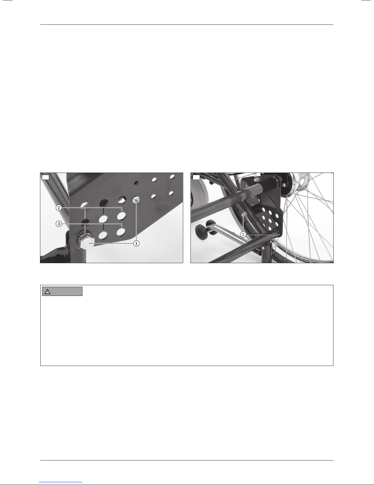
• permissible positions for 22" drive wheels (see fig.40, item 2)
• permissible positions for 24" drive wheels (see fig.40, item 3)
Setting recommendations
Depending on the clinical picture of the user, the intended area of application and the experience/strength of the
attendant, the position of the wheel adapter can be individually readjusted. The safe position of the mobility base
for seating shells on slopes/inclines must be ensured at all times.
Adjusting the wheel adapter
1) Loosen the wheel locks and remove the drive wheels with quick-release axles.
2) Loosen and remove the screw connections on the wheel adapter on both sides (see fig.40, item1; see fig.41,
item1).
3) Adjust the height and depth of the wheel adapter on both sides. Avoid tilting or canting.
4) Insert the screw connections into the appropriate slots on the wheel adapter and firmly tighten them (see
fig.40, item1; see fig.41, item1).
5) Put on the drive wheel with quick-release axle. The quick-release axle must not be removable after releasing the
pushbutton.
6) Readjust the knee lever wheel lock on both sides ().
7) Readjust the anti-tipper (see Page28).
40 41
6.14 Adjusting the brakes
WARNING
Failure to verify brake functionality
Accident, falling of the user due to incorrect adjustment and improperly inflated tyres
► Verify the correct setting of the wheel lock (especially the distance between the wheel lock bolt and tyre).
► Always carry out adjustments to the wheel lock on both sides.
► Ensure that the user can operate the wheel lock without great effort. The force required to do so must not
exceed 60N (~6kg).
► Check the tyre pressure of the drive wheels. Note the information in the section “Technical data” or on the tyre
sidewall.
► Only use original drive wheels with a verified maximum radial out-of-round of 1mm.
6.14.1 Adjusting the knee lever wheel locks
The knee lever wheel lock must be adjusted on both sides when carrying out readjustments.
When changing the position of the drive wheels (for custom fabrication version with 22"/24" drive wheels), both
knee lever wheel locks must be readjusted by moving them on the frame.
Adjusting/readjusting the knee lever wheel lock by sliding it in the slotted hole (for 12" rear wheels)
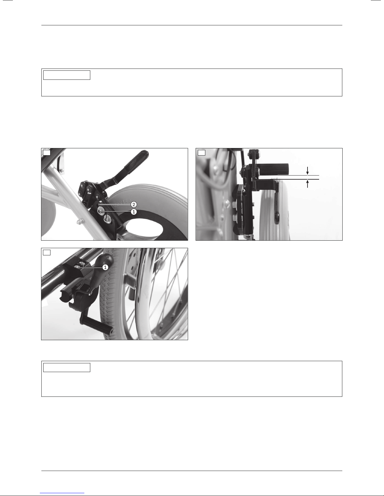
1) Loosen the screw connections on the slotted hole in the clamping plate (see fig.42, item1).
2) The knee lever wheel lock is continuously adjustable in the slotted hole (see fig.42, item2). Set the gap
between the tyre and wheel lock bolt to approx. 5mm when the wheel lock is disengaged (see fig.43).
26
Discovery
Page 27
5mm
Settings
3) Firmly tighten the screw connections on the slotted hole of the clamping plate to a torque of 15Nm.
INFORMATION: Adjust the left and right knee lever wheel locks so that they have the same braking
effect.
Adjusting by shifting on the frame (for custom fabrication version with 22"/24" drive wheels)
INFORMATION
Ottobock Custom Fabrication installs the knee lever wheel lock directly on the 22"/24" drive wheels with a clamp
bracket.
1) Loosen the screw connections on the clamp bracket of the knee lever wheel lock (see fig.44, item1).
2) Shift the clamping mechanism on the main frame. When the wheel lock is not engaged, the gap between the
tyre and the wheel lock bolt should be max. 5mm (not illustrated).
3) Firmly tighten the screw connections on the clamp bracket of the knee lever wheel lock (see fig.44, item1).
INFORMATION: Adjust the left and right knee lever wheel locks so that they have the same braking
effect.
42
44
43
6.14.2 Adjusting the braking force of the drum brake (option)
INFORMATION
After making adjustments, check that activating the manual brake lever creates a sufficient braking effect.
Note that the drum brake must still be able to produce sufficient braking force even when the manual brake lever
is locked into a ratchet position.
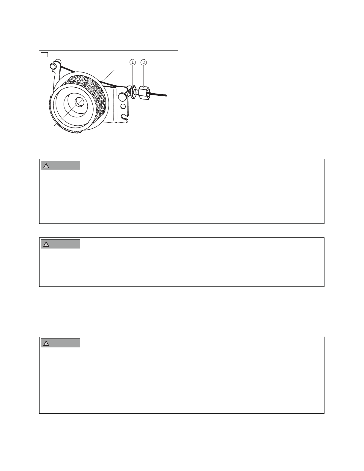
To achieve an optimum braking effect, the braking force is adjusted using the adjustment screw (see fig.45, item
2).
• Increase the braking force: Back off the adjusting screw.
• Reduce the braking force: Screw in the adjustment screw.
1) Loosen the counter nut (see fig.45, item1) and back off the adjustment screw until a scraping noise can be
heard when the rear wheel is rotated.
2) Screw in the adjustment screw (see fig.45, item2) until the scraping noise at the rear wheel disappears and
the wheel runs freely.
27Discovery
Page 28
Settings
3) Tighten the counter nut (see fig.45, item1) until the adjustment screw is fixed.
→ The braking force of both rear wheels must be adjusted equally.
45
6.15 Adjusting the anti-tipper
WARNING
Use of alternative seating systems
Serious injuries to the user due to missing anti-tipper
► If the product is fitted with an alternative seating system or seating shells from other manufacturers, special
attention must be paid to static stability.
► The qualified personnel is obligated to ensure the static stability of such a combination.
► Using an anti-tipper may be required depending on the centre of gravity.
► Verify that the anti-tipper has been installed and adjusted properly.
6.15.1 Discovery Care Chair with 12"/22"/24" rear wheels
WARNING
Incorrect installation of the anti-tipper
Tipping over, falling of the user due to failure to observe the installation instructions
► Adjusting the anti-tipper is not permitted.
► Verify that the anti-tipper has been installed and adjusted properly on both sides. The mounting screw on the
respective anti-tipper tube has to be firmly tightened.
The anti-tipper setting may not be changed when 12" rear wheels are installed. The mounting screw on the anti-tip
per tube has to stay firmly installed (not illustrated).
When 22"/24" rear wheels are installed, the length and height of the anti-tipper can be adjusted separately (see
next section).
6.15.2 Discovery Standard, Discovery for Leckey KIT seat & Leckey Mygo Max or custom fabrica
tion versions with 12"/22"/24" rear wheels
WARNING
Incorrect installation of the anti-tipper/missing anti-tipper
Tipping over, falling of the user due to failure to observe the installation instructions and because of incorrect
adjustment
► Depending upon the settings of the chassis, the centre of gravity, the back angle and the experience of the
user, the use of an anti-tipper may be necessary.
► For a small wheelbase and a backrest that is tilted far back, an anti-tipper may need to be installed on both
sides, depending upon the user's experience.
► Verify that the anti-tipper has been installed and adjusted properly. Find the appropriate position with the
assistance of a helper.
28
Discovery
Page 29
Delivery
CAUTION
Incorrectly adjusted anti-tipper
Tipping over, falling, loss of functionality due to incorrect adjustment
► After it is adjusted, the anti-tipper always has to protrude a few centimetres beyond the outer radius of the rear
wheel.
► The adjustments must always be done in the same way on both sides.
► After making adjustments, take note of the sound made by the anti-tipper locking mechanism as it engages.
► After making any adjustments to the product, verify the proper functionality of the anti-tipper. Adjust the anti-
tipper if needed.
6.15.2.1 Adjustment for 12" rear wheels
With this version, the length/height of the anti-tipper can only be adjusted in one operation.
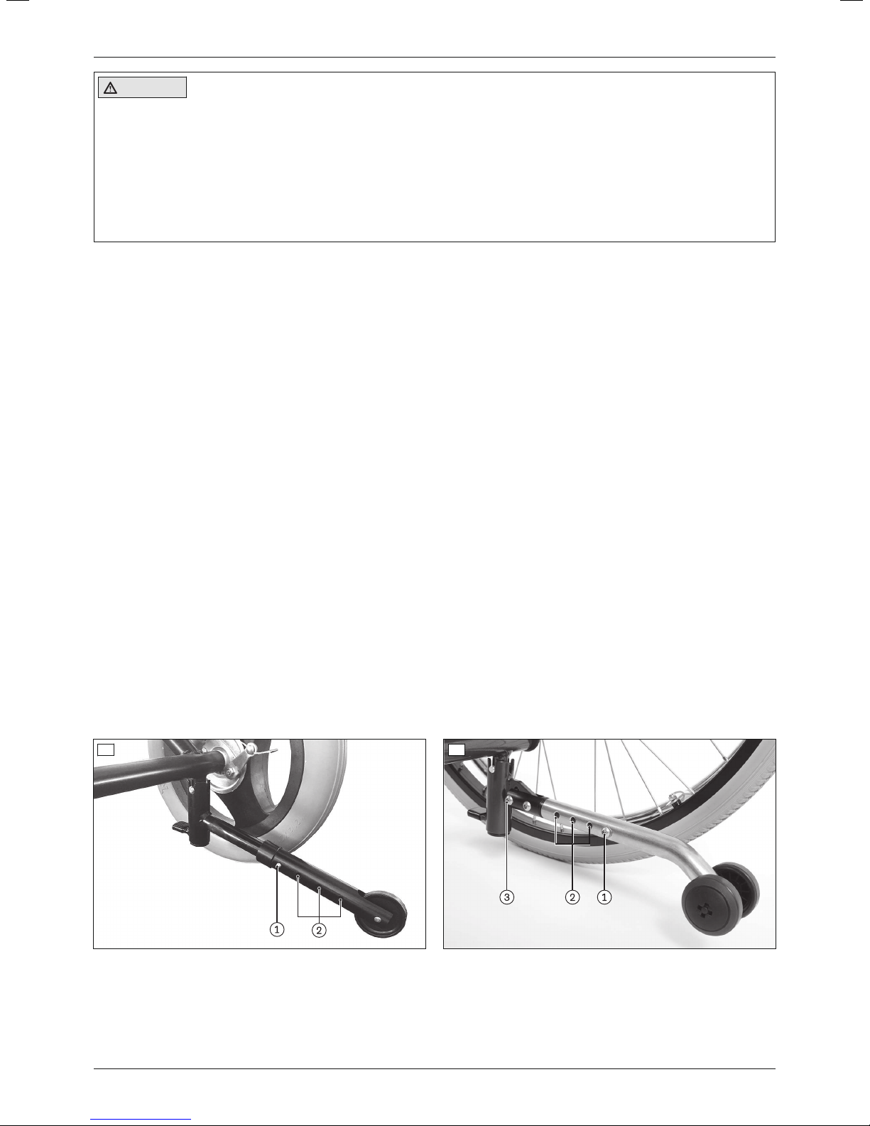
1) Push in the tripod spring on the bar of the anti-tipper (see fig.46, item1).
2) Adjust the length/height of the anti-tipper using the perforated holes (see fig.46, item2).
INFORMATION: The anti-tippers must be no more than 50mm above the floor.
INFORMATION: After making this adjustment, the anti-tipper has to protrude a few centimetres bey
ond the outer radius of the rear wheel.
3) Allow the tripod spring to engage.
4) Check the height of the anti-tipper and readjust it if necessary.
6.15.2.2 Adjustment for 22"/24" drive wheels (custom fabrication version)
With this version, the length and height of the anti-tipper can be adjusted separately.
Adjusting the length of the anti-tipper
1) Loosen and remove the screw connection on the bar of the anti-tipper (see fig.47, item1).
2) Adjust the length of the anti-tipper using the perforated holes (see fig.47, item2).
INFORMATION: After making this adjustment, the anti-tipper has to protrude a few centimetres bey
ond the outer radius of the rear wheel.
3) Insert the screw connection into the appropriate hole on the bar of the anti-tipper and firmly tighten it (see
fig.47, item1).
4) Check the height of the anti-tipper and adjust it if necessary.
INFORMATION: The anti-tippers must be no more than 50mm above the floor.
Adjusting the height of the anti-tipper
1) Loosen and remove the screw connection on the joint of the anti-tipper (see fig.47, item3).
2) Adjust the height of the anti-tipper.
INFORMATION: The anti-tippers must be no more than 50mm above the floor.
3) Insert the screw connection into the appropriate hole on the joint of the anti-tipper and firmly tighten it (see
fig.47, item3).
46 47
7 Delivery
7.1 Final inspection
A final check must be carried out before the wheelchair can be handed over:
29Discovery
Page 30

Maintenance and repair
• Are all options installed according to the order form?
• Do the wheels turn easily?
• Is the seating shell / seating system correctly adapted to the user?
• Is the seating centre of gravity adjusted correctly?
• Are the legrests/armrests (option) adjusted correctly?
• Does the back angle adjustment engage securely in the proper position?
• Can the seat tilt be operated smoothly and securely locked?
• For custom fabrication version with 22"/24" drive wheels: Can the quick-release axles be easily removed
when pulled on firmly and inserted?
• For pneumatic tyres: Is the tyre pressure correct (see Page31)?
• Only after adjustment: Have the brakes (wheel locks) been adjusted correctly?
• If present: Is the anti-tipper mounted and adjusted correctly?
• Are the tripod springs of the arm supports securely engaged?
• Are all screws firmly tightened and all hook-and-loop fasteners firmly fastened?
7.2 Transport to the customer
The mobility base for seating shells should be transported to the user in a completely assembled state using the
outer packaging.
The wheels should be removed if necessary for delivery as a custom fabrication version with 22"/24" drive wheels.
7.3 Handing over the product
The following steps must be performed for the safe handover of the product:
• Have the user get into the product and perform a trial seat fitting. Pay special attention to proper positioning
according to medical considerations.
• In order to ensure that the seat tilt feature operates smoothly, final verification of the seating centre of gravity is
required with the seated user and the designated attendant; adjustments must be made if necessary. The seat
ing centre of gravity must be set so that the attendant can easily change the angle.
• Attendants and – if possible – the user must be instructed in the safe use of the product. In particular, the
enclosed instructions for use (user) are to be used.
• The instructions for use (user) must be issued to the user or an attendant during handover of the wheelchair.
• The user or attendant should acknowledge that they have been instructed in how to use the product and were
informed of the residual risks.
8 Maintenance and repair
The manufacturer recommends regular maintenance of the product every 12 months.
More information on cleaning, disinfection, maintenance and repair can be found in the instructions for use (user).
The service manual contains detailed information on repairs.
9 Disposal
9.1 Disposal information
All components of the product must be disposed of properly in accordance with the respective national environ
mental regulations.
9.2 Information on re-use
CAUTION
Used seat padding
Functional and/or hygienic risks due to re-use
► Replace the seat padding if the wheelchair is to be re-used.
The product is suitable for re-use.
Similar to second-hand machines or vehicles, products that are being re-used are subject to increased strain. Fea
tures and functions must not change in a way that could endanger users or other persons within the product’s
lifespan.
30
Discovery
Page 31
Legal information
The product must first be thoroughly cleaned and disinfected before it can be re-used. Then the product must be
examined by an authorised specialist to check the condition and to look for wear and possible damage. All worn
and damaged parts as well as components which do not fit or are unsuitable for the new user must be replaced.
Detailed information on replacing components as well as information on the required tools and the prescribed ser
vice intervals can be found in the service manual.
10 Legal information
All legal conditions are subject to the respective national laws of the country of use and may vary accordingly.
10.1 Liability
The manufacturer will only assume liability if the product is used in accordance with the descriptions and instruc
tions provided in this document. The manufacturer will not assume liability for damage caused by disregarding the
information in this document, particularly due to improper use or unauthorised modification of the product.
10.2 CE conformity
This product meets the requirements of the European Directive 93/42/EEC for medical devices. This product has
been classified as a class I device according to the classification criteria outlined in Annex IX of the directive. The
declaration of conformity was therefore created by the manufacturer with sole responsibility according to Annex VII
of the directive.
10.3 Warranty
Further information on the warranty terms and conditions is available from the manufacturer's service (see inside
back cover for addresses).
10.4 Service life
Expected service life: 4 years.
The design, manufacturing and requirements for the intended use of the product are based on the expected ser
vice life. These also include the requirements for maintenance, ensuring effectiveness and the safety of the
product.
Using the product beyond the specified expected service life leads to increased residual risk and should only take
place subject to the due diligence and deliberations of qualified personnel.
If the service life is reached, the user or a responsible attendant should contact the qualified personnel who fitted
the product or the manufacturer's servicing department (see inside rear cover or back page for address). Here the
user can obtain information about known risks and the current options for refurbishing the product.
11 Technical data
INFORMATION
► Much of the technical data below is given in mm. Please note that product settings – unless otherwise spe
cified – cannot be adjusted in the mm range but only in increments of approx. 0.5cm or 1cm.
► Note that the values achieved during adjustment may deviate from the values specified below. The deviation
can be ±10mm and ±2°.
INFORMATION
► All measurements indicated below are values which have been theoretically determined.
► Note that not all adjustment possibilities can be used with all wheelchair versions. Furthermore, the adjust
ment combinations are limited by the compact frame geometry.
► Technical changes and tolerances are reserved by the manufacturer.
General information
Discovery
Max. load 110kg (242lbs)
Max. load when using a leg support with continuous
foot support for seating shell interface (steel)
Max. load when using a leg support for short lower leg
lengths
50kg (110lbs)
90kg (198lbs)
31Discovery
Page 32

Technical data
Discovery
Max. load when using a parallel seating shell interface
75kg (165lbs)
(frame width 360mm)
Max. load when using a parallel seating shell interface
100kg (220lbs)
(frame width 400–450mm)
Discovery Minimum Maximum
Gross weight (without user) 18kg 34kg
1)
Weight of the heaviest removable component:
• Leg support with continuous foot support for seat
--- 2.5kg (5.5lbs)
ing shell interface
• Arm support, height-adjustable
• 24" drive wheel
• Leg support, elevating with ratchet joint
• 22" drive wheel
• Leg support, segmented, aluminium
Overall length (with 12" drive wheels)
Overall length (with 22" drive wheels)
Overall length (with 24" drive wheels)
2)
2)
2)
--- 1.9kg (4.2lbs)
--- 1.8kg (4lbs)
--- 1.8kg (4lbs)
--- 1.7kg (3.7lbs)
--- 1.6kg (3.5lbs)
750mm (29.5") 800mm (31.5")
875mm (34.4") 925mm (35.4")
900mm (36.4") 950mm (37.4")
Overall width (with 12" drive wheels) 550mm (21.7") 690mm (27.2")
Overall width (with 22"/24" drive wheels) 570mm (22.4") 710mm (28")
Length (folded) no deviation from overall length
Width (folded) no deviation from overall width
Height (folded) 530mm (20.9") 740mm (29.1")
Static stability, uphill
Static stability, downhill
Static stability, sideways
Dynamic stability, uphill
3), 4)
--- 10° (17.6%)
4)
4)
4)
--- 12° (21.3%)
--- 10° (17.6%)
--- 6° (10.5%)
Seat bottom angle (seat tilt) 0° 35°
Effective seat depth 405mm (16") 480mm (19")
Effective seat width 360mm (14.5") 500mm (20")
Front seat height
5)
450mm (17.7") 550mm (21.6")
Back support angle 0° 30°
Back support height 440mm (17.3")
(standard)
Distance foot support to seat bottom
Angle between leg support and seat bottom
Distance arm support to seat bottom
Distance front edge of arm support to front edge of
6)
7)
6)
130mm (5.1") 350mm (13.8")
5° 85°
60mm (2.4") 390mm (15.4")
140mm (5.5") 145mm (5.7")
620mm (24.4")
(extended)
wheelchair
Handrim diameter 490mm (19.3") 540mm (21.3")
Horizontal axle position 150mm (5.9") 300mm (11.8")
Minimum turning radius
Adjustment range, push handles/push bars
8)
9)
740mm (29.2") ---
--- ~ 200 mm (8")
Load capacity of storage bag (optional) --- 5kg (11lbs)
1)
Encompasses the maximum installation of accessories, including tray
2)
Without seating unit and activated anti-tipper; varies depending on installed leg support
3)
2x anti-tipper mandatory with Care Chair version
4)
Depending on seat positioning
5)
At full tilt, with 12" drive wheels: 470mm (18.5")
6)
Discovery with seat plate without seat cushion; other seating systems vary
7)
Depending on the type of leg support, maximum value with elevating leg support
8)
Discovery Standard with 360mm frame width and 12" drive wheels; in accordance with ISO7176-5
32
Discovery
Page 33
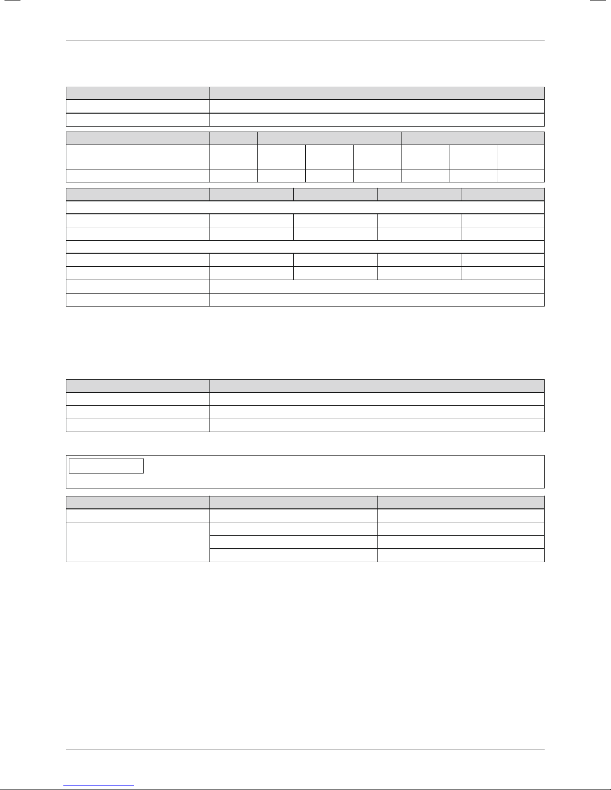
Appendices
9)
Not with option of 600mm back support height with deep back support bracket
Additional information
Discovery
Tyre types Pneumatic or tubeless PU tyres
Front wheels 8"
Rear wheels / drive wheels 12" 22" 24"
Wheelbase 480mm
(18.9")
Seat tilt
1)
0°–35° 0°–22.5° 0°–35° 0°–35° 0°–17.5° 0°–20.5° 0°–35°
480mm
(18.9")
505mm
(19.9")
530mm
(20.9")
480mm
(18.9")
505mm
(19.9")
530mm
(20.9")
Frame width 360mm (14.5") 400mm (16") 450mm (18") 500mm (20")
Distance between arm supports
without spacers 370mm (14.6") 420mm (16.5") 470mm (18.5") 520mm (20.5")
with spacers 420mm (16.5") 470mm (18.5") 520mm (20.5") 590mm (23.2")
Transport weights
2)
Frame with 12" rear wheels 18kg (39.7lbs) 18.5kg (40.8lbs) 19.5kg (43lbs) 20kg (44.1lbs)
Frame with 22"/24" drive wheels 26kg (57lbs) 26.5kg (58.4lbs) 27kg (59.5lbs) 27.5kg (60.6lbs)
22" drive wheel (pair) 3.4kg (7.5lbs)
24" drive wheel (pair) 3.6kg (7.9lbs)
1)
with standard installation of compression springs. The adjustment range can be limited to 15° with the custom
fabrication version with 22"/24" drive wheels and lashing points.
2)
Discovery Standard without leg supports, arm supports and seating unit; the specified weights vary according to
the selected options and model.
Environmental conditions
Discovery
Ambient temperature –10°C to +40°C (14°F to 104°F)
Storage temperature –10°C to +40°C (14°F to 104°F)
Relative humidity 45% – 85%
Permissible tyre pressure (for pneumatic tyres)
INFORMATION
Note the safety instructions regarding air pressure and tyres.
Wheel Wheel size Tyre pressure
1)
Caster wheel 8" 2.5bar (250kPa; 36psi)
Drive wheel
12" 2.5bar (250kPa; 36psi)
22" 2.5bar (450kPa; 65psi)
24" 6bar (600kPa; 87psi)
1)
see also print on the tyre wall
12 Appendices
12.1 Required tools
The following tools are required for adjustments and maintenance work:
• Allen wrenches in sizes 4, 5, 6
• Ring and open-end wrenches in sizes 8, 10, 13, 19 and 24
• Phillips head screwdriver (size: 2)
• Screwdriver (blade width: 3mm)
• Torque wrench (measurement range 5-50 Nm)
12.2 Torque values of the screw connections
Unless otherwise specified, screw connections are tightened with the following torque values:
33Discovery
Page 34

Appendices
• Thread diameter M4: 3Nm
• Thread diameter M5: 5Nm
• Thread diameter M6: 10Nm
• Thread diameter M8: 25Nm
34
Discovery
Page 35

Kundenservice/Customer Service
Europe
OttoBock HealthCare DeutschlandGmbH
Max-Näder-Str. 15 · 37115 Duderstadt · Germany
T+495527848-3433 · F+495527848-1460
[email protected] · www.ottobock.de
Otto Bock Healthcare Products GmbH
Brehmstraße 16 · 1110 Wien · Austria
F +431 5267985
[email protected] · www.ottobock.at
Otto Bock Adria d.o.o. Sarajevo
Ramiza Salčina 85
71000 Sarajevo · Bosnia-Herzegovina
T+387 33 255-405 · F+387 33 255-401
[email protected] · www.ottobockadria.com.ba
Otto Bock Bulgaria Ltd.
41 Tzar Boris III‘ Blvd. · 1612 Sofia · Bulgaria
T+35928057980 · F+35928057982
[email protected] · www.ottobock.bg
OttoBock Suisse AG
Luzerner Kantonsspital 10 · 6000 Luzern 16 · Suisse
T+41414556171 · F+41414556170
[email protected] · www.ottobock.ch
Otto Bock ČR s.r.o.
Protetická 460 · 33008 Zruč-Senec · Czech Republic
T+420377825044 · F+420377825036
[email protected] · www.ottobock.cz
OttoBock Iberica S.A.
C/Majada, 1 · 28760 Tres Cantos (Madrid) · Spain
T+34 918063000 · F+34 918060415
[email protected] · www.ottobock.es
Otto Bock France SNC
4 rue de la Réunion - CS 90011
91978 Courtaboeuf Cedex · France
T+33169188830 · F+33169071802
[email protected] · www.ottobock.fr
Otto Bock Healthcare plc
32, Parsonage Road · Englefield Green
Egham, Surrey TW20 0LD · United Kingdom
T +441784 744900 · F +441784 744901
[email protected] · www.ottobock.co.uk
OttoBock Hungária Kft.
Tatai út 74. · 1135 Budapest · Hungary
T+36 14511020 · F+36 14511021
[email protected] · www.ottobock.hu
Otto Bock Adria d.o.o.
Dr. Franje Tuđmana 14 ·10431 Sveta Nedelja · Croatia
T+38513361544 · F+38513365986
[email protected] · www.ottobock.hr
OttoBock Italia Srl Us
Via Filippo Turati 5/7 · 40054 Budrio (BO) · Italy
T+39 051692-4711 · F+39 051692-4720
[email protected] · www.ottobock.it
Otto Bock Benelux B.V.
Mandenmaker 14 · 5253 RC
Nieuwkuijk · The Netherlands
T+31735186488 · F+31735114960
[email protected] · www.ottobock.nl
Industria Ortopédica Otto Bock Unip. Lda.
Av. Miguel Bombarda, 21 - 2º Esq.
1050-161 Lisboa · Portugal
T+351213535587 · F+351213535590
[email protected]
OttoBock Polska Sp. z o. o.
Ulica Koralowa 3 · 61-029 Poznań · Poland
T+48 616538250 · F+48 616538031
[email protected] · www.ottobock.pl
OttoBock Romania srl
Şos de Centura Chitila - Mogoşoaia Nr. 3
077405 Chitila, Jud. Ilfov · Romania
T+40 214363110 · F+40 214363023
[email protected] · www.ottobock.ro
OOO Otto Bock Service
p/o Pultikovo, Business Park „Greenwood“,
Building 7, 69 km MKAD
143441 Moscow Region/Krasnogorskiy Rayon
Russian Federation
T+74955648360 · F+74955648363
[email protected] · www.ottobock.ru
OttoBock Scandinavia AB
Koppargatan 3 · Box 623 · 60114 Norrköping · Sweden
T+4611280600 · F+4611312005
[email protected] · www.ottobock.se
OttoBock Slovakia s.r.o.
Röntgenova 26 · 85101 Bratislava 5 · Slovak Republic
T+421232782070 · F+421232782089
[email protected] · www.ottobock.sk
OttoBock Sava d.o.o.
Industrijska bb · 34000 Kragujevac · Republika Srbija
T+38134351671 · F+38134351671
[email protected] · www.ottobock.rs
OttoBock Ortopedi ve
Rehabilitasyon Tekniği Ltd. Şti.
Mecidiyeköy Mah. Lati Lokum Sok.
Meriç Sitesi B Blok No: 30/B
34387 Mecidiyeköy-İstanbul · Turkey
T+902123565040 · F+902123566688
[email protected] · www.ottobock.com.tr
Africa
Otto Bock Algérie E.U.R.L.
32, rue Ahcène Outaleb - Coopérative les Mimosas
Mackle-Ben Aknoun · Alger · DZ Algérie
T+21321913863 · F+21321913863
[email protected] · www.ottobock.fr
Otto Bock Egypt S.A.E.
28 Soliman Abaza St. Mohandessein - Giza · Egypt
T+20 2 37606818 · F+20 2 37605734
[email protected] · www.ottobock.com.eg
Otto Bock South Africa (Pty) Ltd
Building 3 Thornhill Office Park · 94 Bekker Road
Midrand · Johannesburg · South Africa
T +27 11 564 9360
[email protected]
www.ottobock.co.za
Americas
Otto Bock Argentina S.A.
Av. Belgrano 1477 · CP 1093
Ciudad Autônoma de Buenos Aires · Argentina
T+54115032-8201 / 5032-8202
[email protected]
www.ottobock.com.ar
Otto Bock do Brasil Tecnica Ortopédica Ltda.
Alameda Maria Tereza, 4036, Bairro Dois Córregos
CEP: 13.278-181, Valinhos-São Paulo · Brasil
T +55 19 3729 3500 · F +55 19 3269 6061
[email protected] · www.ottobock.com.br
Otto Bock HealthCare Canada
5470 Harvester Road
Burlington, Ontario, L7L 5N5, Canada
T+1 800 665 3327 · F+1 800 463 3659
[email protected] ·
www.ottobock.ca
Oficina Ottobock Habana
Calle 3ra entre 78 y 80.
Edificio Jerusalen · Oficina 112 · Calle 3ra.
Playa, La Habana. Cuba
T+53720 430 69 · +53720 430 81
[email protected]
www.ottobock.com.br
Otto Bock HealthCare Andina Ltda.
Calle 138 No 53-38 · Bogotá · Colombia
T+5718619988 · F+5718619977
[email protected] · www.ottobock.com.co
Otto Bock de Mexico S.A. de C.V.
Prolongación Calle 18 No. 178-A
Col. San Pedro de los Pinos
C.P. 01180 México, D.F. · Mexico
T+525555750290 · F+525555750234
[email protected] · www.ottobock.com.mx
Otto Bock HealthCare LP
11501 Alterra Parkway Suite 600
Austin, TX 78758 · USA
T+1 800 328 4058 · F+1 800 962 2549
[email protected]
www.ottobockus.com
Asia/Pacific
Otto Bock Australia Pty. Ltd.
Suite 1.01, Century Corporate Centre
62 Norwest Boulevarde
Baulkham Hills NSW 2153 · Australia
T+61288182800 · F+61288144500
[email protected] · www.ottobock.com.au
Beijing Otto Bock Orthopaedic Industries Co., Ltd.
B12E, Universal Business Park
10 Jiuxianqiao Road, Chao Yang District
Beijing, 100015, P.R. China
T+861085986880 · F+861085980040
[email protected]
www.ottobock.com.cn
Otto Bock Asia Pacific Ltd.
Unit 1004, 10/F, Greenfield Tower, Concordia Plaza
1 Science Museum Road, Tsim Sha Tsui
Kowloon, Hong Kong · China
T +852 2598 9772 · F +852 2598 7886
[email protected] · www.ottobock.com
Otto Bock HealthCare India Pvt. Ltd.
20th Floor, Express Towers
Nariman Point, Mumbai 400 021 · India
T +91 22 2274 5500 / 5501 / 5502
[email protected] · www.ottobock.in
OttoBock Japan K. K.
Yokogawa Building 8F, 4-4-44 Shibaura
Minato-ku, Tokyo, 108-0023 · Japan
T+8133798-2111 · F+8133798-2112
[email protected] · www.ottobock.co.jp
OttoBock Korea HealthCare Inc.
4F Agaworld Building · 1357-74, Seocho-dong
Seocho-ku, 137-070 Seoul · Korea
T+822577-3831 · F+822577-3828
[email protected] · www.ottobockkorea.com
OttoBock South East Asia Co., Ltd.
1741 Phaholyothin Road
Kwaeng Chatuchark · Khet Chatuchark
Bangkok 10900 · Thailand
T+6629303030 · F+6629303311
[email protected] · www.ottobock.co.th
Other countries
Otto Bock HealthCare GmbH
Max-Näder-Straße 15 · 37115 Duderstadt · Germany
T+49 5527848-1590 · F+495527848-1676
[email protected] · www.ottobock.com
Page 36

Ihr Fachhändler | Your specialist dealer
Otto Bock Mobility Solutions GmbH
Lindenstraße 13 · 07426 Königsee-Rottenbach/Germany
www.ottobock.com
© Ottobock · 647G1286=en-02-1801
 Loading...