

Page 1
1
2 3
4 5 6
7 8
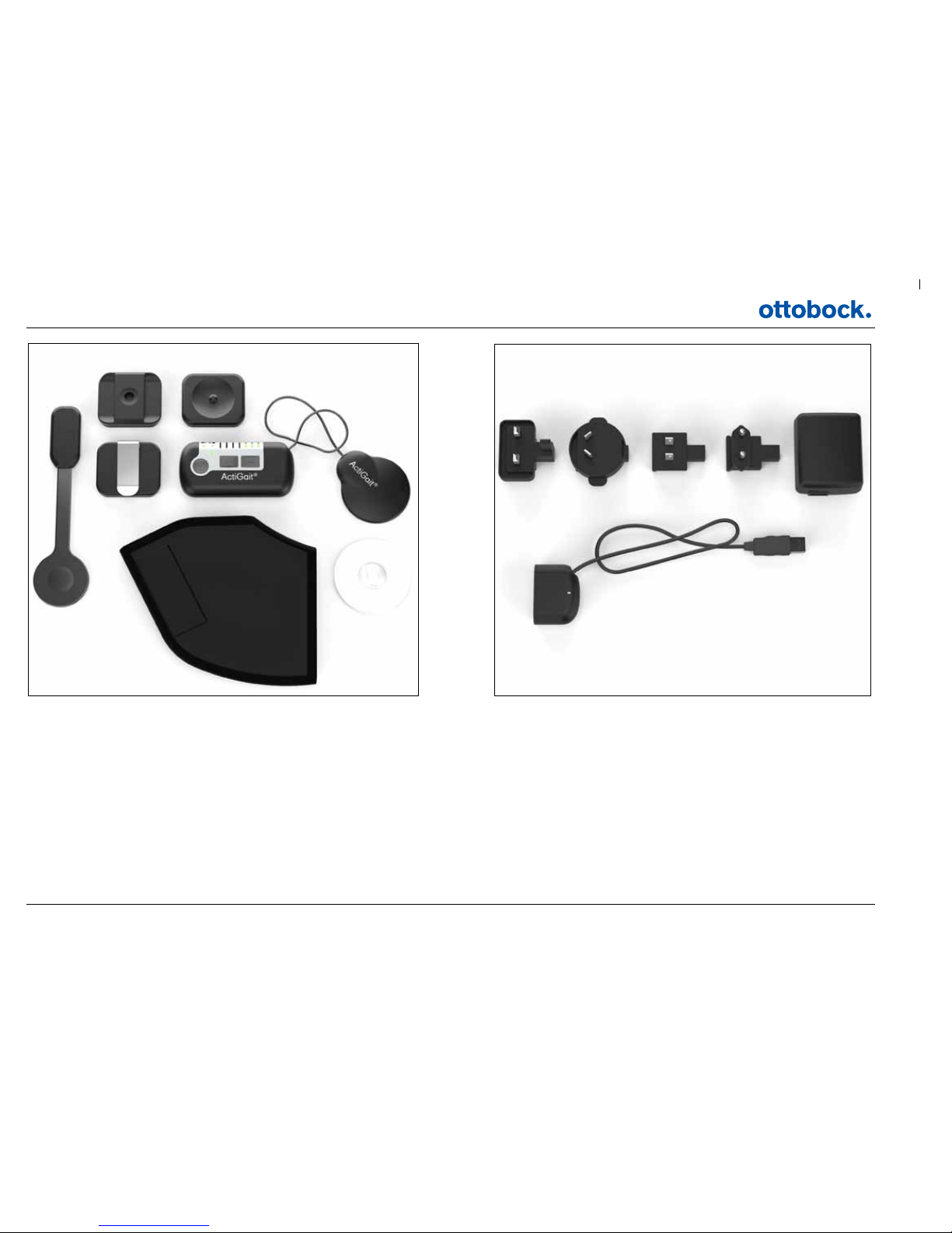
1: ActiGait® Heel Switch
2: ActiGait® Belt Loop
3: ActiGait® Body Clip
4: ActiGait® Belt Clip
5: ActiGait® Control Unit
6: ActiGait® Antenna
7: ActiGait® Heel Sock
8: ActiGait® Antenna Fixture
9: ActiGait® Charger (model FW7711/0.7) incl. plugs
10: ActiGait® Charger Cable
9a 9b 9c 9d
9
10
Page 2
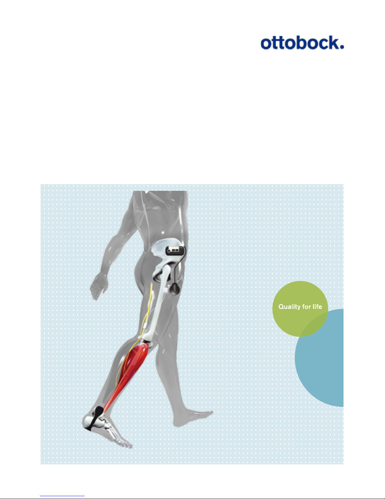
ActiGait® Implantable Drop Foot Stimulator
User Manual
Page 3

2
1. Introduction ...................................... 3
2. Intended Use .................................... 3
2.1 Medical Purpose .................................... 3
2.2 Application............................................. 3
2.3 Qualification of Clinician .......................... 3
2.4 Follow up Schedule ................................ 3
3. Indications/Contraindications .... 4
3.1 Indications ............................................ 4
3.2 Contraindications ................................... 4
4. Warnings and Precautions ........... 5
4.1 Safety precautions ................................. 5
4.2 Warnings ............................................... 5
4.3 General cautions ................................... 7
4.4 Potential Risks/Side effects ..................... 9
5. Service Information ...................... 11
5.1 Scope of Delivery ................................. 11
5.2 Service ................................................ 11
6. Description of the ActiGait® ....... 12
6.1 The ActiGait® Implant ........................... 13
6.2 The ActiGait® ....................................... 14
7. How ActiGait® works ................... 15
7.1 The Control Unit ................................... 16
7.1.1 The On/Off Button ............................. 17
7.1.2 The Stimulation Intensity Buttons ......... 18
7.1.3 The Mute Button ................................ 19
7.1.4 The Pairing Button ............................. 21
7.1.5 The Control Unit Battery Indicator ........ 22
7.1.6 The Heel Switch Battery Indicator ........ 23
7.1.7 Training Mode Indicator ...................... 25
7.1.8 Mute Indicator ................................... 27
7.1.9 Stimulation Intensity Indicators ............ 27
7.2 Putting On the Control Unit .................... 27
7.2.1 The Belt Clip ..................................... 28
7.2.2 The Belt Loop .................................... 28
7.2.3 The Body Clip ................................... 29
7.3 Putting On the Antenna Fixture ............... 30
7.4 Putting On the Antenna ......................... 33
7.5 The Heel Switch ................................... 35
7.5.1 The Heel Sock ................................... 36
7.5.2 Heel Switch Feedback........................ 37
7.6 The Charger ........................................ 38
7.6.1 Charging the Control Unit ................... 39
7.6.2 Travel Kit for Charger ......................... 41
7.7 Audio Signals and Warnings .................. 42
7.7.1 Warnings .......................................... 42
7.7.2 Audio Signals .................................... 43
8. Lights and Audio Signals............ 43
8.1 How to Interpret the Light Indicators ....... 44
8.2 How to Interpret the Audio Signals ......... 46
9. Troubleshooting for ActiGait® ... 49
10. Warranty ......................................... 51
11. Expected lifetime ....................... 52
12. Cleaning, Storage and
Disposal ........................................... 52
12.1 Cleaning ............................................ 52
12.2 Storage............................................. 53
12.3 Disposal ............................................ 53
13. Available Articles ....................... 53
14. Technical Data .............................. 55
14.1 ActiGait® Control Unit.......................... 55
14.2 ActiGait® Belt Clip .............................. 56
14.3 ActiGait® Belt Loop ............................. 56
14.4 ActiGait® Body Clip ............................ 57
14.5 ActiGait® Antenna .............................. 57
14.6 ActiGait® Antenna Fixture ..................... 58
14.7 ActiGait® Heel Switch .......................... 58
14.8 ActiGait® Heel Sock ............................ 59
14.9 19.9 ActiGait® Charger Cable .............. 59
14.10 ActiGait® Charger ............................. 60
14.11 ActiGait® Implant .............................. 61
14.11.1 X-Ray Identication ......................... 62
15.Classication ................................ 62
16. List of symbols ............................. 63
16.1 Ingress Protection ............................... 65
17. Declaration of Conformity ....... 65
Page 4

3
1. Introduction
This manual describes the use of the ActiGait® and is directed towards individuals
with an ActiGait® Implant. The manual is to be used as an information resource and
an instruction manual. The term “User” denes individuals who have an ActiGait®
Implant and thereby are users of the ActiGait®.
For clinicians the Clinician Manual (647G805=GB) is available
2. Intended Use
2.1 Medical Purpose
The ActiGait® is solely to be used as treatment in patients having a drop foot following an upper motor neuron lesion.
2.2 Application
The ActiGait® system is a partially implantable medical device for treatment of drop
foot which activates the muscles of the lower leg during walking. The system is
intended for use by persons suering from paralysis of the ankle dorsiexor muscles
caused by damage to the central nervous system. The largest group of potential users
are persons with hemiplegia as a consequence of stroke. The system will not function
for people with drop foot caused by peripheral nerve damage.
2.3 QualicationofClinician
The selection of users for ActiGait®, setup and adjustment are done by clinicians such
as medical doctors, physiotherapists or equivalent. To be able to program and adjust
the ActiGait®, the clinician must have obtained a certicate on usage of the Clinical
Station software following training by Otto Bock
2.4 Follow up Schedule
It is recommended that the ActiGait® is activated 1-3 weeks after implantation, as the
wound healing must be nished rst. The user should thereafter be followed closely
with 2-3 follow-ups during the rst 6 months for ne-tuning of the settings and gen-
eral guidance. Subsequently, the user should be seen in the clinic on request.
Page 5

4
3. Indications/Contraindications
Potential candidates for the ActiGait® are stroke patients with drop foot. The pa-
tients who may benet from use of the ActiGait® are characterized by lacking the
ability to obtain normal heel contact during gait. It must be possible to correct the
heel contact by electrical stimulation of the peroneal nerve.
3.1 Indications
The individuals must:
• have a one-sided hemiparesis persisting for at least 6 months due to a cerebro-
vascular accident (CVA)
• be fully grown-up
• be able to walk 20 m in less than 2 minutes with or without a walking aid but
without the help of another person
• have a reduced speed of walking
• be able to stand upright with both heels touching the oor while hip and knee
are in neutral position
• have a passive range of movement of the aected ankle joint of at least 30 de-
grees
• have a positive response to surface electrical stimulation of the peroneal nerve –
i.e. muscle contraction results in ankle dorsiexion and improved gait
3.2 Contraindications
Individuals with:
• peripheral nerve damage in the aected leg
• severe or uncontrolled diabetes mellitus with peripheral nerve involvement
• poor skin condition on the aected leg
• a thickness of subcutaneous adipose layer on the thigh exceeding 40 mm.
1
• inability to walk 100 m without stopping prior to CVA (with or without a walking
aid, but without the help of another person)
• poorly controlled epilepsy
• need for Ankle Foot Orthosis (AFO) to maintain ankle stability
• concomitant medical and psychological conditions, which would limit the suc-
cess of the ActiGait®, such as: active degenerative diseases of the back and legs,
neglect or drug abuse
1 Individuals who by visual inspection seem to have an adipose layer of about 40 mm at the
site where the stimulator should be placed must undergo a more precise examination to
measure the exact thickness of the adipose layer (e.g. using ultrasonic measurement
methods.)
Page 6

5
• concomitant medical and psychological conditions, which would compromise
the safety of the patient in connection with the implantation and use of the ActiGait®, such as: severe cardiac disease, uncontrolled hypertension or history of
malignancy within the preceding ve years
• other active implanted devices, such as demand pacemakers or implanted debrillators, as mutual electromagnetic interference may distort the ecacy of both
devices and expose the patient to dangerous situations
4. Warnings and Precautions
4.1 Safety precautions
Neurodan A/S is solely responsible for the safety, reliability, and function of the
apparatus on the condition that repairs, adjustments, and alterations, incl. replacement of batteries, have been carried out by an individual appointed by Neurodan
A/S and when the apparatus is used in accordance with the manual.
The ActiGait® and the ActiGait® Accessories contain radio circuits approved by the
relevant authorities. Changes or modications to any part of the ActiGait® or the
ActiGait® Accessories could void your authority to operate the equipment.
Maintenance may only be carried out by trained personnel. It is the responsibility of
the physician to inform the patient about all potential risks, warnings and precautions.
It is the responsibility of the clinician to instruct the patient in the correct use of the
ActiGait® and to inform the patient to contact the clinician about any discomfort
while using the ActiGait®.
4.2 Warnings
• The ActiGait® is a device for treatment of drop foot, and must be considered and
used accordingly. Stimulation of other nerves besides the peroneal nerve with the
ActiGait® involves a risk of potentially hazardous side eects. It is not meant as a
device that eliminates or cures any condition.
• Implanting the ActiGait® Implant requires experience in peripheral nerve operations and handling of active implantable medical devices. Training is performed
by self-study of the Surgeon Manual and the following steps:
Page 7

6
• Attending product training by OB personnel
• Observing or assisting in the implantation of an ActiGait® Implant by an
experienced surgeon
• Performing the rst surgery under supervision of a surgeon experienced in
the procedure
• The clinicians, who select the patients and set up the ActiGait® stimulation,
must be properly trained by someone experienced in patient selection and
programming of the ActiGait®. The trainer must be authorized by Otto Bock. Im-
proper selection of patients and programming of the ActiGait® may result in lack
of eect of stimulation or lack of improvement of gait. Improper selection and
programming may expose the patient to dangerous situations, discomfort or pain
and the risk of falling during walking.
• ActiGait® patients should not engage in any activity which leaves them in a dangerous situation if the ActiGait® fails.
• The ActiGait® should not be exposed to therapeutic levels of ultrasound energy,
as the device may inadvertently concentrate the ultrasound eld and cause harm.
• Shortwave or microwave diathermy should not be used. Both the heating and
non-heating modes of operation pose a risk of tissue destruction. If given any
medical treatment in which an electrical current is passed through the body from
an external source, care should be taken to monitor the functioning of the ActiGait® Implant during the initial stages of treatment.
• The electronic components of the ActiGait® Implant may be damaged by thera-
peutic ionizing radiation. This kind of damage may not be immediately detect-
able.
• Application of magnetic resonance imaging (MRI) or spectroscopy techniques to
a patient with the ActiGait® Implant involves a risk of potentially hazardous side
eects. Patients with an ActiGait® Implant should seek medical guidance before
entering environments with strong magnetic or electromagnetic elds, such as
magnetic resonance (MR) scanners or strong radio-transmitters or radars, includ-
ing areas protected by a warning notice preventing entry by patients tted with
a pacemaker, as strong electromagnetic elds may heat the device excessively or
result in uncontrolled pulses.
• Use of electrical stimulation in pregnancy involves a risk of potentially hazardous side eects. For use during pregnancy qualied medical guidance should be
obtained.
• Extended periods of time with the legs in a xed position, e.g. during travelling,
should be avoided as this may cause uid retention in the leg.
Page 8

7
• The ActiGait® may not be used at an ambient temperature of more than 40° C
due to risk of skin burn2. If the ambient temperature is above 40°C, the surface
temperature of the ANT can exceed the intended maximum temperature of
42.5°C (the intended maximum temperature will not cause any harm to the skin).
However, if any problems occur, please contact your local ActiGait® representative or your clinician.
• The ActiGait® may be interfered with by other equipment, even if that other
equipment complies with CISPR emission requirements.
4.3 General cautions
• The ActiGait® should not be exposed to extreme pressure as this will damage the
device.
• The external parts of the ActiGait® (e.g. the Control Unit, Antenna and Heel
Switch) should not be immersed in water as this will damage the device. Proper
maintenance instructions must be followed and the external parts should be
shielded e.g. when walking in rain.
• The ActiGait® should not be used in areas where explosives are used or stored
due to radio interference.
• This equipment has been tested and found to comply with the limits for a Class
B digital device, pursuant to part 15 and part 18 of the FCC Rules. These limits
are designed to provide reasonable protection against harmful interference in a
residential installation. This equipment generates, uses and can radiate radio
frequency energy and, if not installed and used in accordance with the instructions, may cause harmful interference to radio communications. However, there
is no guarantee that interference will not occur in a particular installation. If
this equipment does cause harmful interference to radio or television recep-
tion, which can be determined by turning the equipment o and on, the user
is encouraged to try to correct the interference by one or more of the following
measures:
• Reorient or relocate the receiving antenna.
• Increase the separation between the equipment and receiver.
• Connect the equipment into an outlet on a circuit dierent from that to
which the receiver is connected.
• Consult the dealer or an experienced radio/TV technician for help
2 In warm weather you must be extra aware of skin irritation where the ActiGait® is in contact
with your skin. In case of skin irritation you should remove the ActiGait®.
Page 9
8
• The ActiGait® is radio controlled and may be disturbed by interfering devices;
consequently, the eectiveness of the ActiGait® can be disturbed. In this situation you should move away from the source of the disturbance or turn o your
ActiGait®.
• The external parts of the ActiGait® must be turned o on airplanes during a
ight, as the radio transmission may interfere with other devices. Because the
Heel Switch cannot be turned o it should be taken o and removed from the
body during the ight to avoid activation of the switch.
• The ActiGait® may only be used at an atmospheric pressure between 700 hPa to
1060 hPa.
• Magnetic cards, such as bank or credit cards, should not be kept near the Control
Unit, the Antenna plug, the Charger Cable, the Clinical Interface, the Body Clip,
Belt Clip and Belt Loop at any time, as these devices contain magnets that may
demagnetize a magnetic card.
• Magnetic cards, such as bank or credit cards, should not be kept near the Anten-
na while the ActiGait® is in use, as the card may become demagnetized.
• Wireless communication equipment such as wireless home network devices, mo-
bile phones, DECT telephones and their base stations, Bluetooth devices etc. may
disturb the ActiGait® during its use. These devices should be kept at a distance
from the ActiGait® according to the table below.
• The Control Unit should be removed from the patient’s body while charging the
Control Unit or when the Control Unit is connected to a PC with the Clinical Inter-
face to eliminate the risk of the patient being exposed to electrical shock.
• The ActiGait® should never be connected to other cables, e.g. extension cables,
than the ones supplied with the ActiGait®. If another cable is used and this cable
is defect there will be a risk of electrical shock or overheating of the equipment.
• Only the ActiGait® Charger and ActiGait® Charger Cable should be used for charging the ActiGait®. Further, the ActiGait® Charger and ActiGait® Charger Cable
should not be used for charging other equipment than the ActiGait®. In such a
case, the manufacturer will not be liable for any damages.
Device type Distance
Mobile phone 0.33 m
DECT telephones (incl. base stations) 0.12 m
Wlan 0.23 m
Bluetooth devices 0.075 m
Page 10

9
• The internal batteries in the Control Unit and Heel Switch are not replaceable. If
you open the Control Unit or Heel Switch, the seals will be broken and you will
compromise the ingress protection. The Control Unit battery has a life time of
5 years. When the capacity of the Control Unit battery is no longer sucient to
last for 1 day of use, the Control Unit should be discarded and replaced with a
new one. When the Heel Switch battery runs out of power, the whole Heel Switch
must be discarded and replaced with a new one.
• The ActiGait® should not be used while operating dangerous machines, which
require foot or leg operation with the aected leg, such as motor vehicles, air-
planes, industrial machinery etc., as failure of the ActiGait® may leave the patient
in a dangerous situation.
• The ActiGait® fullls all technical and legal requirements for use in the European
Community. The ActiGait® has not yet been formally investigated for use outside
this area. ActiGait® uses a wireless communication technology. Restrictions of
its use may exist in some countries outside the area mentioned above. Please
contact your local ActiGait® representative if in doubt whether the ActiGait® may
be used in a specic area outside the European Community.
• There is a risk of rupture of the skin if the sutures are removed earlier than 14
days post surgery.
• Preoperative use of antibiotics is recommended to reduce the risk of infection.
Infection is a potential hazard at any kind of surgery and the principle of preop-
erative use of antibiotics is therefore generally accepted.
• If the leg is not bandaged with elastic bandage or antithrombotic stocking up to
the groin after surgery, uid collections, such as oedema, may occur around the
Implant.
4.4 Potential Risks/Side effects
As with all surgical procedures, the implantation of a stimulation system involves
some risks. In addition to those normally associated with surgery, the implantation
and use of the ActiGait® carries the following risks:
• Infection
• Accidental damage of the nerve during surgery
• Subjects undergoing anticoagulation therapies may be at greater risk for post
operative complications such as hematomas
• Reoperation due to malfunction of the Implant
Page 11

10
• Nerve damage in the case of the cu electrode constricting the nerve
• Skin reactions to the material of the external components of the ActiGait® (Heel
Switch and Antenna Fixture) in permanent contact with the body
• Device extrusion/migration
• In the presence of strong, environmental electromagnetic elds the device may
heat excessively or send out uncontrolled pulses to the nerve
• If the ActiGait® malfunctions and the device does not stimulate, the patient may
stumble
• Intolerable sensory stimulation during use (pain or paresthesia)
• Muscle pain may result from too high stimulation intensity or continuous stimu-
lation
• Pain in the ankle joint or other joints of the aected and non-aected lower limbs
may result from a change in movement pattern or improper programming of the
ActiGait®
• The distance between the Implant and the Antenna of the external device may
exceed 40 mm due to swelling around the Implant after operation, general
oedema, or increase in the subcutaneous adipose layer
• Damage to the external parts of the ActiGait® due to improper cleaning methods
• Inability to produce an acceptable dorsiexion movement due to 1) excessive
spasticity, 2) improper programming of the ActiGait® or 3) movement or incorrect
installation of the cu-electrode
The safety of the ActiGait® has been documented by evaluating reports on Device
Related Adverse Events and measurements of conduction velocity of the common
peroneal nerve (branches for extensor digital muscles, anterior tibial muscle and
peroneal muscles) before and three months after implantation.
Page 12
11
5. Service Information
5.1 Scope of Delivery
The term “ActiGait®” is dened as the parts of the system that you have in or on your
body. Besides this you will be given various “ActiGait® accessories” that you need for
maintaining your ActiGait®. To be able to use the ActiGait® system you will need the
following items:
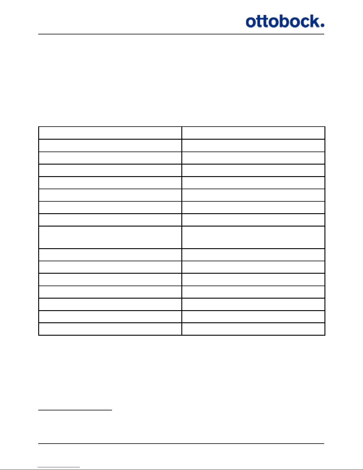
Item Part Number
ActiGait®
1 ActiGait® Control Unit 9002=11
One of the following xtures
1 ActiGait® Belt Clip
9002M=11A
1 ActiGait® Body Clip
9002M=11B
1 ActiGait® Belt Loop
9002M=11C
1 ActiGait® Antenna 9002=13
1 package of ActiGait®
Antenna Fixtures of 15 pieces
9002=M03
1 ActiGait® Heel Switch 9002=12
1 ActiGait® Heel Sock 9002M=12
3
ActiGait® Accessories
1 ActiGait® User Manual 647G808=country code
1 ActiGait® Charger 9002=14
1 ActiGait® Charger Cable 9002=15
1 ActiGait® User Suitcase 9002=17
5.2 Service
The ActiGait®must be set up and put into service in accordance with the information
provided in this manual. Check ActiGait® for any visible damage before every use. In
case of damage, malfunction or unexpected operation or events, contact your clinician or local ActiGait®representative.
3
3 The Heel Socks have the following number format: 9002M=12[Size-Color code]. Sizes:
XS=Extra Small, S=Small, M=Medium, L=Large, XL=Extra Large, XXL= Extra Extra Large.
Color code: 0=Beige, 6=White, 7=Black
Page 13
12
Contact your local ActiGait®representative for assistance, if needed, in setting up,
using or maintaining the ActiGait®.
Modication of the equipment is not allowed. If the equipment is modied by an
unauthorized person or organization, the responsibility and liability for the equipment is transferred to the person/organization modifying it.
6. Description of the ActiGait®
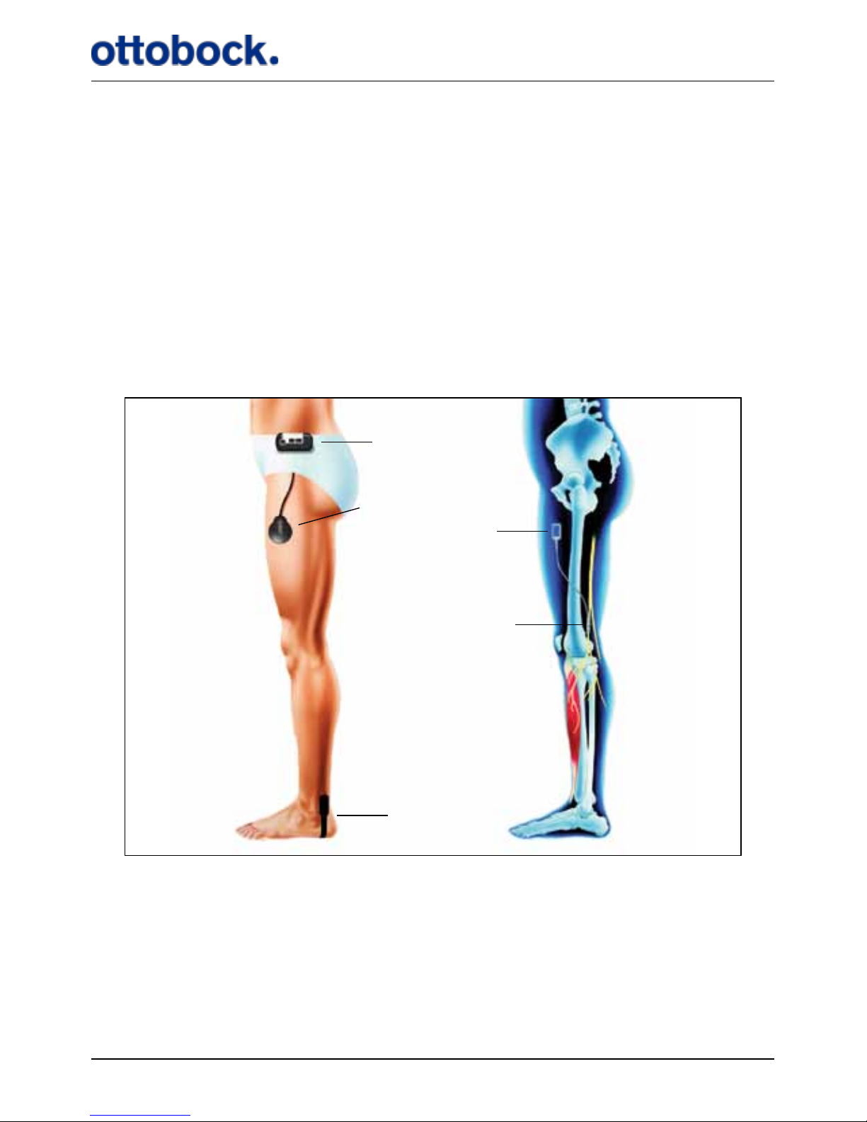
The ActiGait® Implant and other main parts of the ActiGait® are illustrated in Figure 1.
Figure 1: The Implant and other main parts of the ActiGait® and their locations during use.
Control Unit
Heel Switch
Cu Electrode
Stimulator body
Antenna
The purpose of the ActiGait®is to lift your foot during the swing phase of walking.
When you walk, the Heel Switch detects your heel strike and heel lift and transmits
signals wirelessly to the Control Unit. If you have the Heel Switch on the aected
foot, the Control Unit sends power and control signals to the Antenna on your thigh
when it receives a heel lift signal. The Antenna then transmits power to the im-
Page 14
13
planted stimulator through the skin via an inductive link and the Implant activates
the muscles which produce a foot lift while you bring the aected leg forward in the
swing phase. When you put your heel down again, the Control Unit receives a heel
strike signal from the Heel Switch. The stimulation will continue shortly so that your
foot will be set down in a well balanced way.
If you have the Heel Switch on the unaected foot, the muscles on the aected leg
will be activated by a heel strike instead of heel lift to produce the foot lift at the correct time. You can choose which foot you want to carry the Heel Switch on according
to your preference and your clinician’s advice. However, you can only switch from
one foot to the other when you are at the clinic because your clinician must set up
the stimulation timing accordingly.
Your clinician can connect the Control Unit to a PC and adjust the stimulation intensity and the timing with a dedicated ActiGait® software program so that it matches
your gait pattern and walking speed. The clinician will set a range within which you
can adjust the stimulation intensity with the Control Unit. Only trained clinicians
can adjust the ActiGait®.
6.1 The ActiGait® Implant
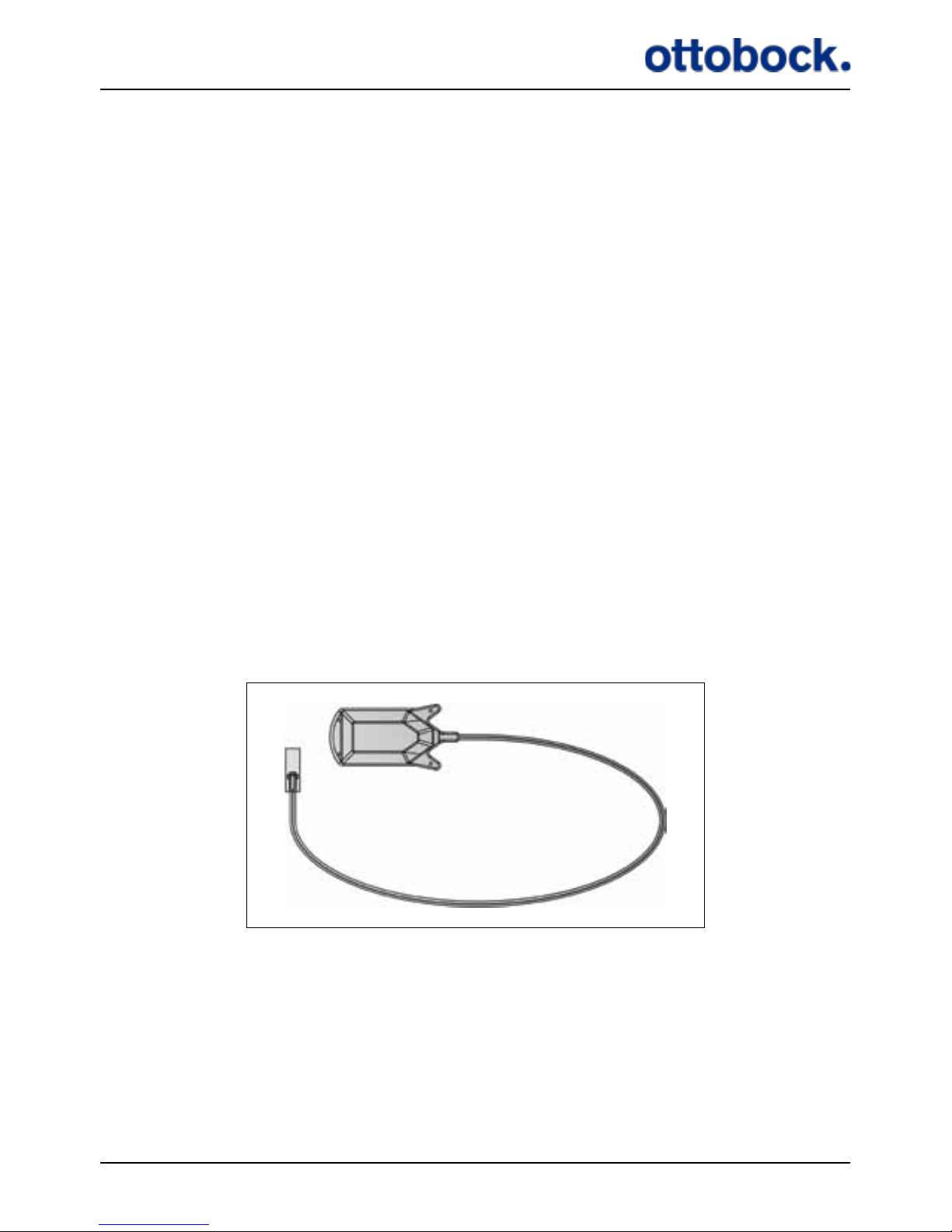
The Implant consists of a stimulator body (1), a cu electrode (2) and a cable (3).
The Implant does not have an internal power source (such as a battery) and is ac-
tivated through magnetic induction from an external power source. The Implant is
as such passive, and it is necessary to have an ActiGait® Control Unit and ActiGait®
Antenna to activate it.
Figure 2: The Implant
1
2
3
Page 15
14
The stimulator body (1) contains the receiver coil and electronics. The coil converts
the signal from the external Antenna into an electrical current, which both powers
and controls the Implant.
The cable (3) consists of eight individual metal wires, coiled in two bundles of
four. The wires are individually coated with ETFE (Teon), and the two bundles
are inserted into a dual-lumen silicone tube. This design allows the cable to stretch
slightly and makes it resistant to exion and extension.
The cu electrode (2) is a silicone cu, 23 mm long with 12 platinum/iridium con-
tact discs located on the inside. These discs form the electrical contact to the nerve.
The electrode contacts are organized as four sets of three, each triplet making up
one channel. The four channels are distributed evenly around the nerve, in order to
allow selective stimulation of dierent fascicles inside the nerve.
6.2 The ActiGait®
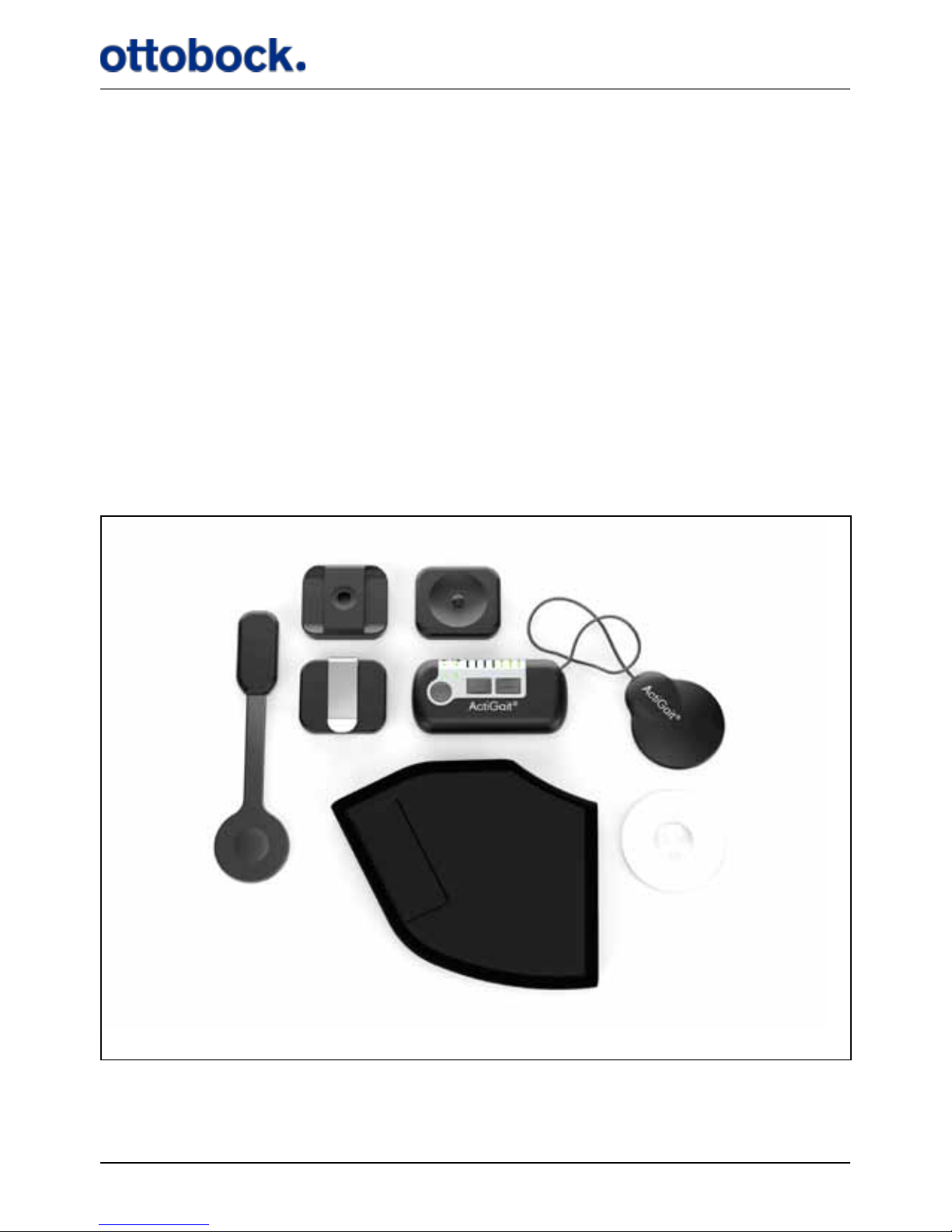
The ActiGait® consists of the Heel Switch (1), the Belt Loop (2), the Body Clip (3),
the Belt Clip (4), the Control Unit (5), the Antenna (6), the Heel Sock (7) and the
Antenna Fixture (8) (see Figure 3).
1
7
3
8
54
2
Figure 3: The ActiGait®. 1: Heel Switch, 2: Belt Loop, 3: Body Clip, 4: Belt Clip, 5: Control Unit, 6: An-
tenna, 7: Heel Sock, 8: Antenna Fixture
6
Page 16
15
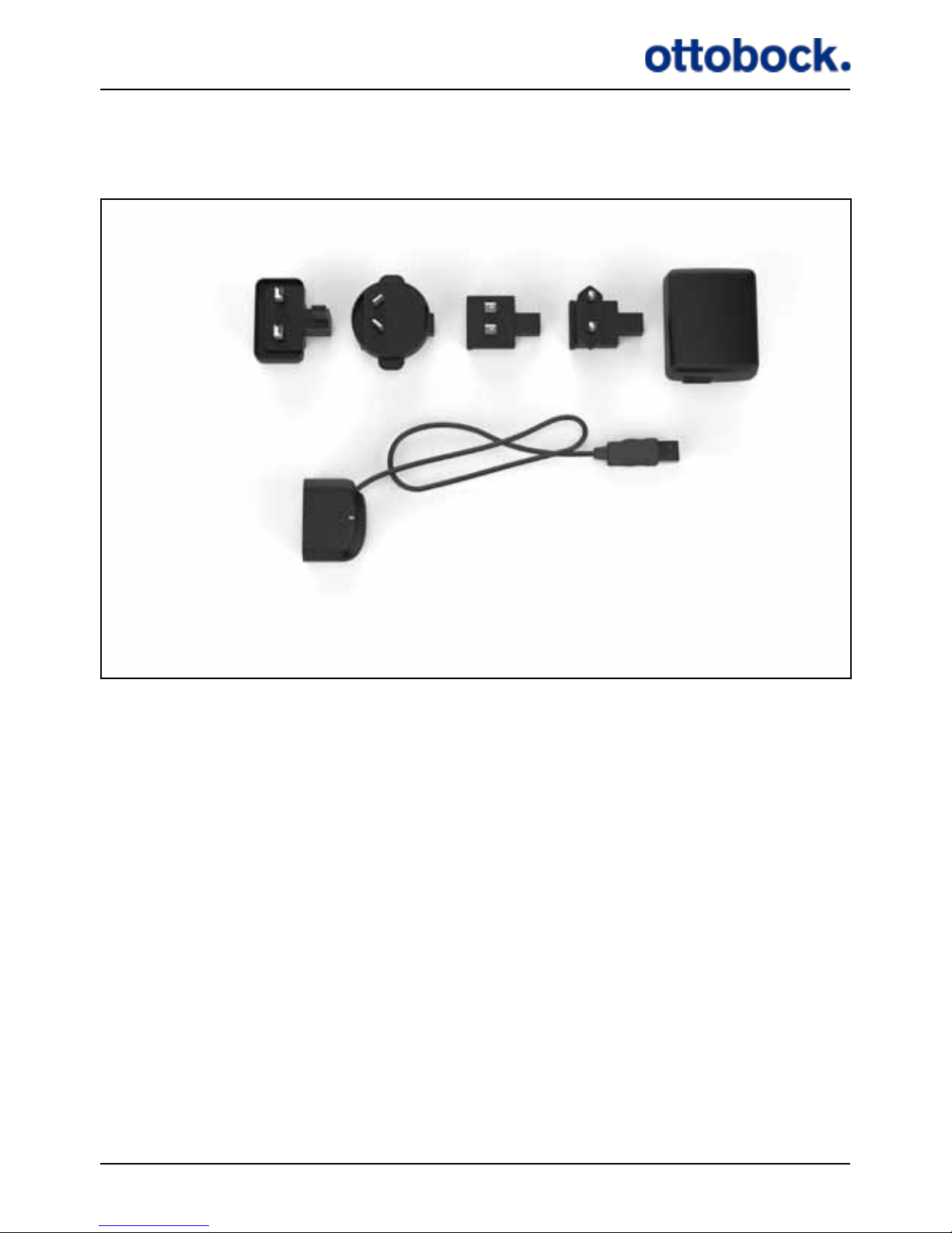
Furthermore, you will be supplied with the accessories shown in Figure 4, i.e. the
Travel Kit for the Charger consisting of 4 dierent plugs (9), the Charger (10) and the
Charger Cable (11).
7. How ActiGait® works
When you receive your ActiGait®, the package will contain the items shown in
Figure 3 and Figure 4. This chapter explains everything about the ActiGait®and its
accessories.
9a 9d9b
9c
10
11
Figure 4: ActiGait® accessories. 9: Travel kit for Charger, 10: Charger, 11: Charger Cable
Page 17
16
7.1 The Control Unit
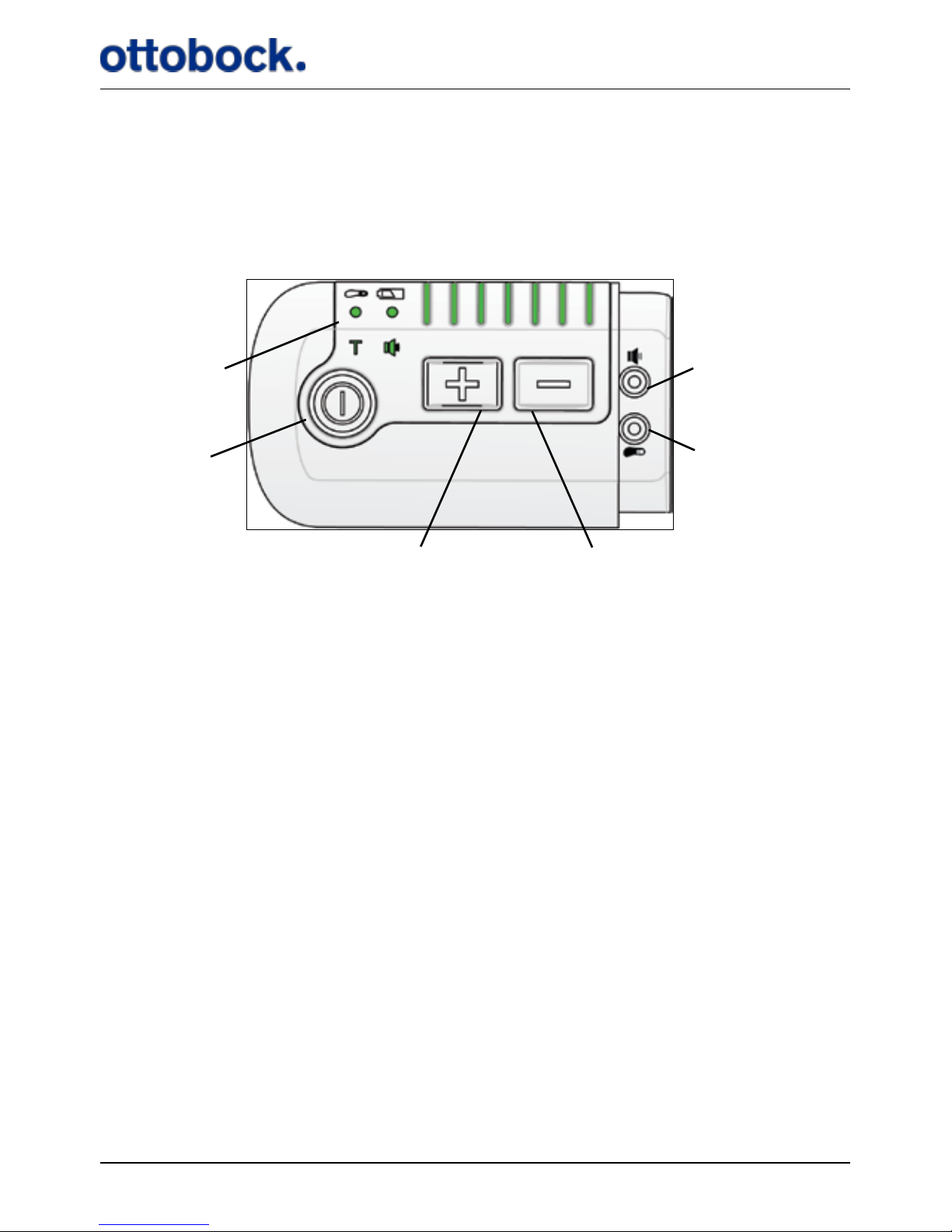
The Control Unit (Figure 5) controls the implanted stimulator via the Antenna,
which must be located on the skin on top of the implanted stimulator. The Control
Unit receives signals from the Heel Switch (see section 7.5 on page 35) about
when to stimulate.
The various buttons are described in the following sections. The Control Unit should
be carried at the waist but additional positions are also possible. On the back of the
Control Unit there is a magnet that keeps the Control Unit xed to the various xtures used for carrying the Control Unit (see section 7.2 on page 27 about Control
Unit xation).
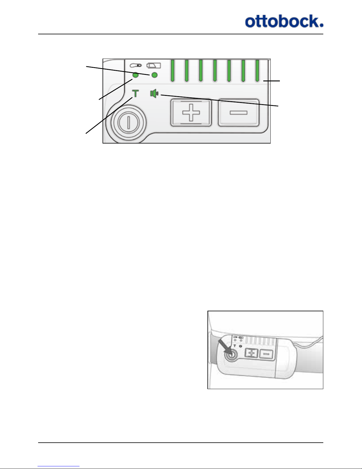
The Control Unit has a number of light indicators that show the status of the Control
Unit (see Figure 6)
Figure 5: The control Unit
Light indicators
On/o button
Intensity up button Intensity down button
Pairing button
Mute button
Page 18
17
Figure 6: The light indicators on the Control Unit
Control Unit
battery indicator
Training mode
indicator
Mute indicator
Stimulation
intensity
indicators
Heel Switch battery
indicator/Heel Switch
Feedback indicator
The light indicators are described in the following sections:
• Control Unit battery indicator: Section 7.1.5 on page 22.
• Heel Switch battery indicator/Heel Switch Feedback indicator: Section 7.1.6 on
page 23, and section 7.5.2 on page 37
• Training mode indicator: Section 7.1.7 on page 25
• Stimulation intensity indicators: Section 7.1.2 on page 18
• Mute indicator: Section 7.1.8 on page 27, page 36
7.1.1 The On/Off Button
The on/o button is used for switching the ActiGait® Control Unit on and o. You
must press the on/o button for at least 1.5 seconds to activate it.
Press the on/o button for at least 1.5 seconds
to switch the Control Unit on or o.
Page 19
18
Every time the Control Unit is switched on it performs an indicator check. This
means that all light indicators will ash once and a short beep is heard. This can be
used for diagnostics because it shows if any of the light indicators or the buzzer is
defect. If a light indicator is defect the function will most likely still be intact. When
you switch o the Control Unit a long beep is heard. If the mute indicator (see section 7.1.8 on page 27) is red the beeps are not heard.
During use, the lights on the Control Unit will power down to save power. This
means that the lights are turned o 30 seconds after the latest activation of a button
but stimulation will continue as normal. When the lights of the Control Unit are
powered down, a press on any button will switch the lights back on. The rst press
of a button when the lights of the Control Unit are powered down will therefore not
activate this button’s usual function.
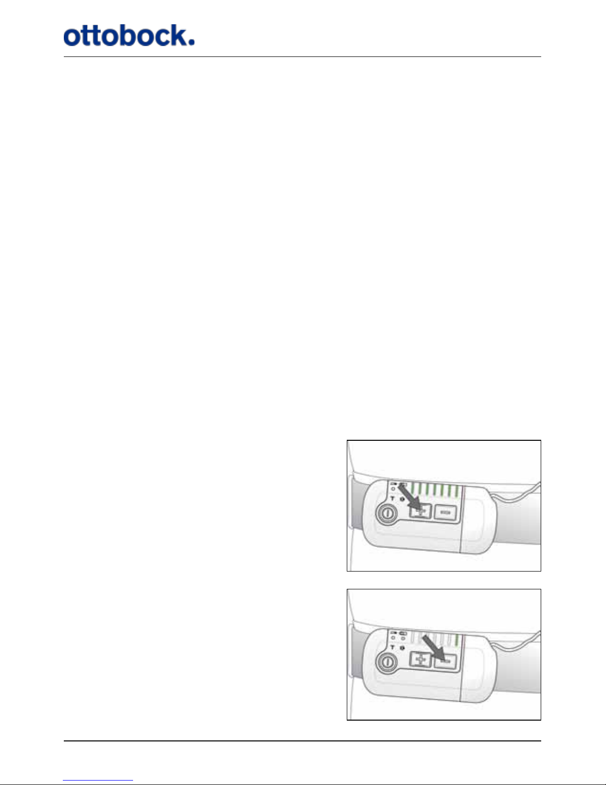
7.1.2 The Stimulation Intensity Buttons
When you walk you might experience that you sometimes need more stimulation
than other times to get an adequate foot lift. This can depend on the kind of surface
that you are walking on, your shoes, if you are tired or experience spasticity. You
can turn the stimulation intensity up and down at any time with the intensity up (+)
and intensity down buttons (–) on the Control Unit.
Turning the stimulation intensity up =
increasing the foot lift…
…and down = decreasing the foot lift
Page 20
19
The row of light indicators on top of the Control Unit shows the current intensity
level of the stimulation. There are 7 light indicators so the stimulation intensity can
be adjusted in 7 steps. Your clinician will set the range within which you can adjust
the stimulation intensity with the Control Unit.
If you press the intensity up button when the stimulation intensity is already at the
highest level, you will hear a long beep to let you know that the stimulation intensity cannot be increased further. Likewise, if you press the intensity down button
when the stimulation intensity is already at the lowest level, you will hear a short
beep. If the mute indicator is red (see section 7.1.8 on page 27) these beeps are
not heard.
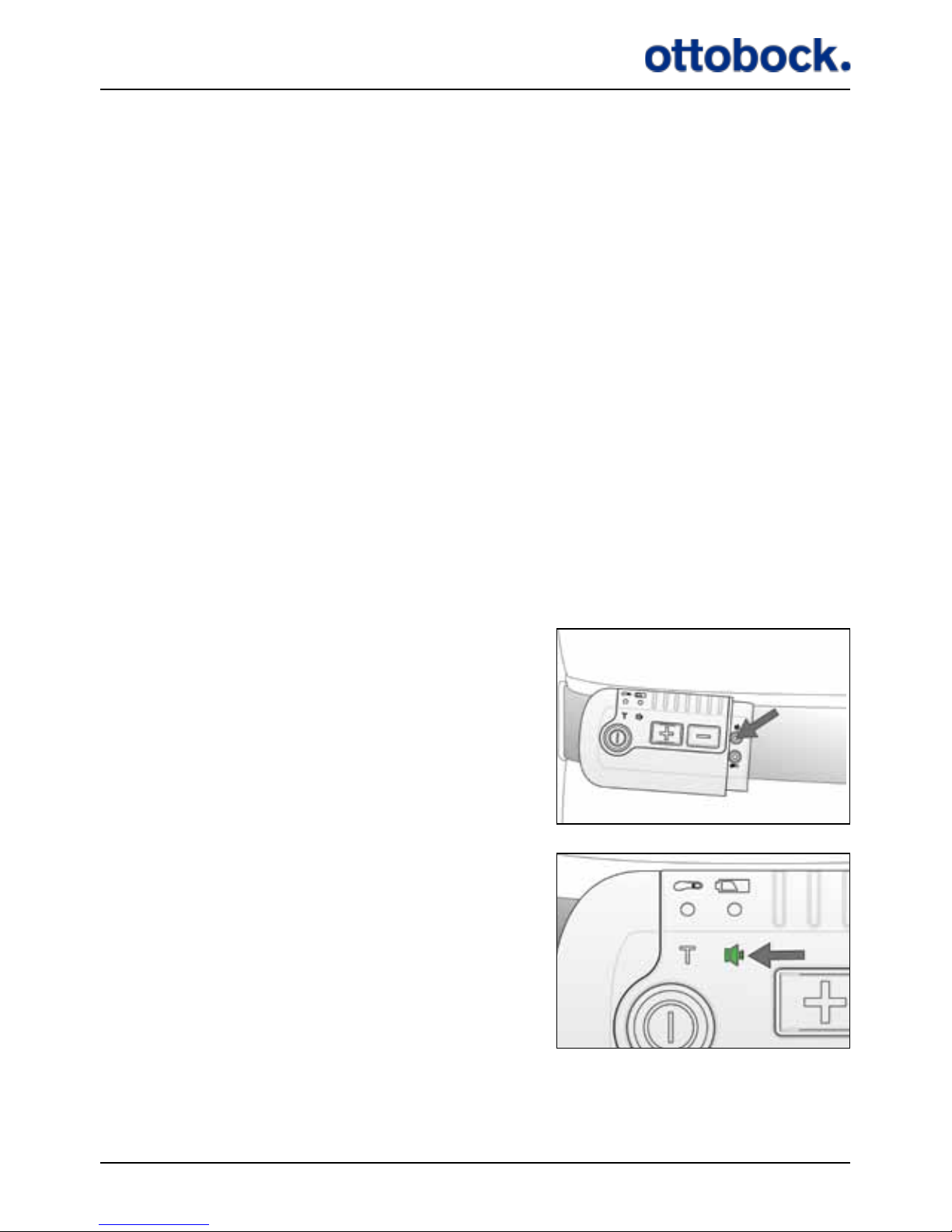
7.1.3 The Mute Button
The mute button is used for switching o the sounds from the Control Unit. The
mute button is hidden under the Antenna plug, so you must disconnect the Antenna
from the Control Unit to access it. The mute button is a pencil button, meaning that
you must use a pencil or another pointy tool to press it. The mute button is marked
with the same icon as the mute light indicator.
Press the mute button with a pencil or similar.
The current mute setting is shown by the mute
light indicator.
Page 21
20
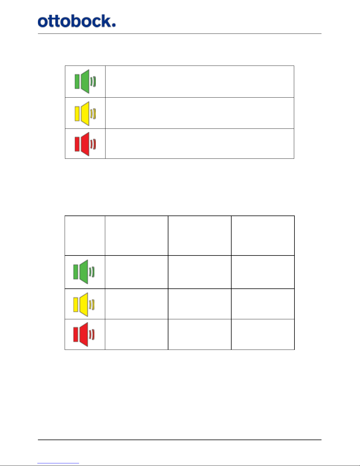
The mute button has three settings:
As default, all sounds are activated and therefore the mute light indicator is green.
If you press the mute button once, the light indicator turns yellow and if you press
it once more, it turns red. The settings of the various audio signals are listed in
Table 1.
Warnings cannot be muted, only audio signals. See section 7.7.2 on page 43 for
explanation of the audio signals
All sounds are on.
All sounds are on, except for the Heel Switch feedback.
All sounds are o, except for warnings.
Table 1: Mute settings
Stimulation
Intensity
maximum or
minimum
Heel Switch
feedback
Indicator
check
On On On
On O O
O O O
Page 22
21
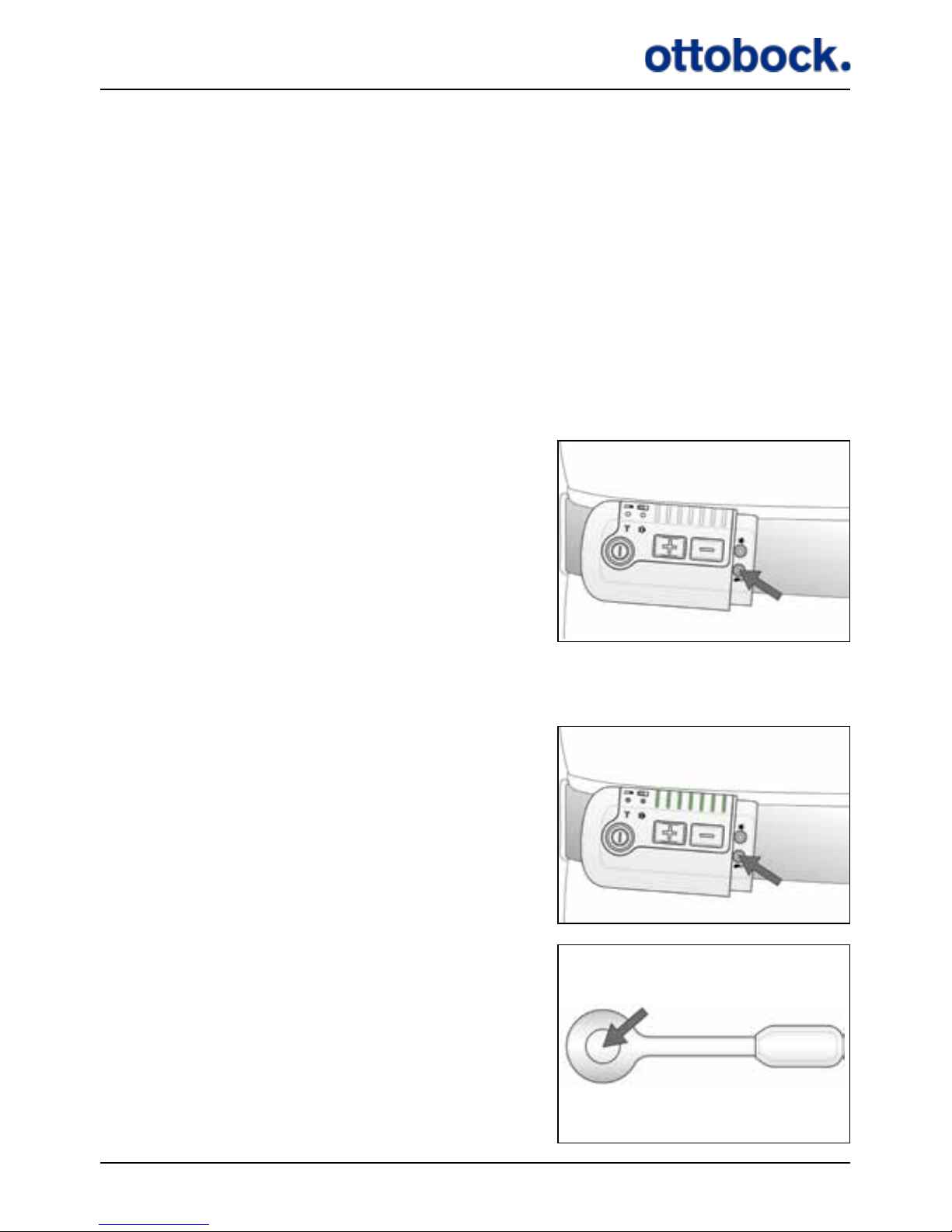
7.1.4 The Pairing Button
To avoid that another user’s Heel Switch can communicate with your Control Unit,
your Control Unit must be set up to only recognize your Heel Switch. This is called
pairing. The pairing button is a pencil button hidden under the Antenna plug below
the mute button. The pairing button is marked with the same icon as the heel switch
light indicator.
Each Control Unit can be paired with up to 4 Heel Switches at the same time. If you
pair a fth Heel Switch, the rst one will be erased from the Control Unit’s memory.
When you start using a new Heel Switch or Control Unit always remember to pair
them.
Press the pairing button with a pencil or similar…
…all indicators will light up…
…press the Heel Switch once. Your Control Unit
and Heel Switch are now paired and the lights
of the Control Unit are turned o.
Page 23
22
Note that if the Control Unit is powered down you must press the pairing button
twice; rst to activate the Control Unit and second to pair the Control Unit and Heel
Switch.
Be aware that you will get a warning when you press the Heel Switch to indicate that
the Antenna is not connected to the Control Unit. This is only the case if you usually
wear the Heel Switch on the non-aected leg.
7.1.5 The Control Unit Battery Indicator
The Control Unit is powered by an internal rechargeable battery. You must charge
the Control Unit with the ActiGait® Charger and it is recommended that you make a
habit of charging the Control Unit regularly, e.g. every night (see section 7.6 on page
38 about the Charger and how to charge the Control Unit). The Control Unit bat-
tery is not exchangeable.
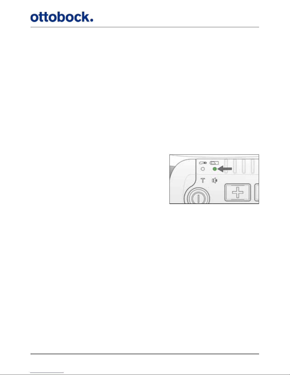
The Control Unit battery indicator.
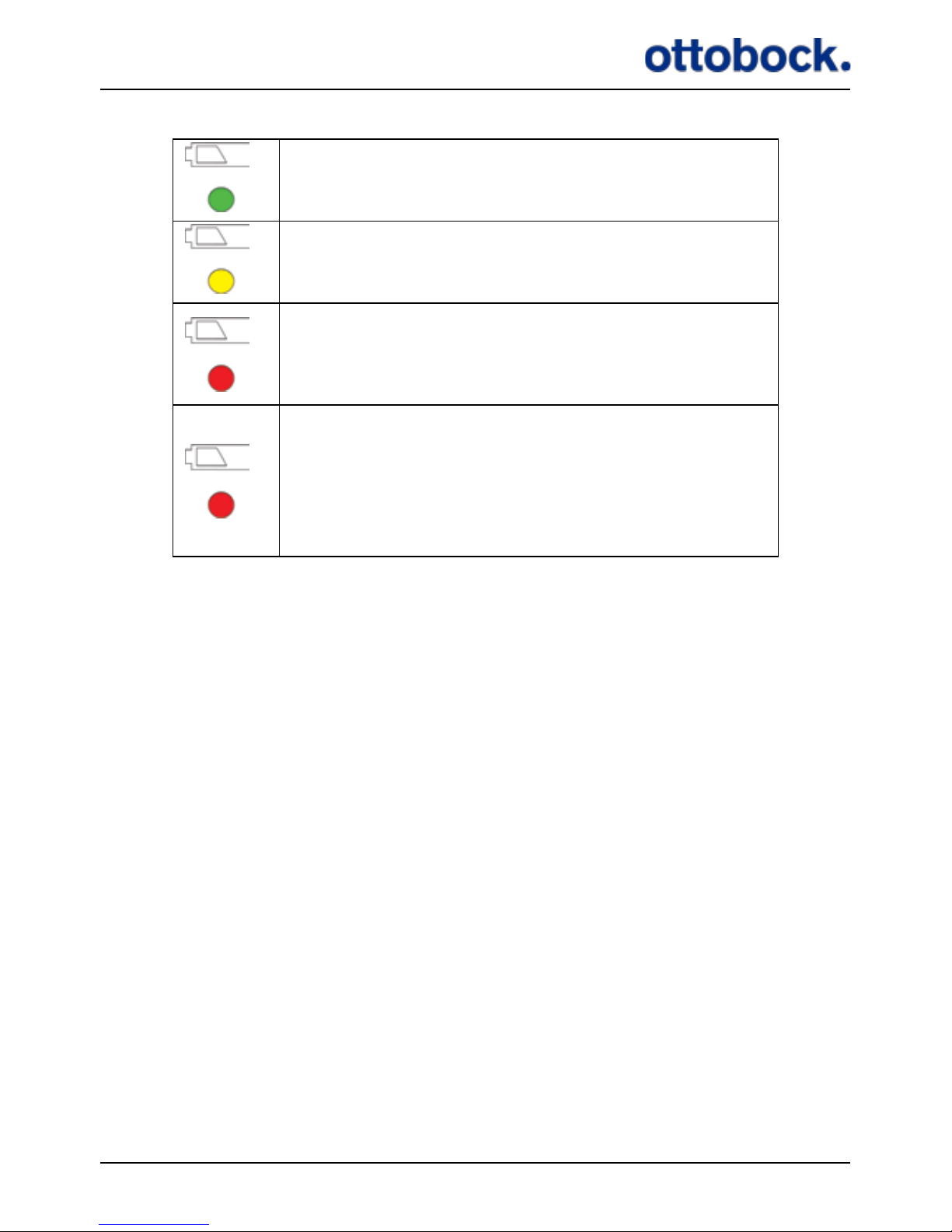
The color of the Control Unit battery indicator can be green, yellow or red reecting
how much power you have left on the Control Unit.
Page 24
23
The battery level of the Control Unit is normal and
you have power for at least one day of walking.
The battery level of the Control Unit is medium and
you have power for less than one day.
Red and the Control Unit beeps once every 30 seconds: The battery level is low and you have power
for less than 2 hours. Charge the Control Unit as
soon as you can.
Red and ashing while other light indicators are
turned o and the Control Unit beeps for 8 seconds
with an interval of 30 seconds:
The Control Unit is out of power and stimulation
has stopped. Turn o the Control Unit until you can
charge it.
When the Control Unit battery is out of power, both this light indicator and the light
indicator for the Heel Switch battery will ash and the Control Unit will beep for 8
seconds, while all other light indicators are switched o. You can tell which of the
two batteries is low by checking which one of the two is red: the Control Unit battery
indicator or the Heel Switch battery indicator.
It is recommended that you charge the Control Unit every night to avoid running out
of power at an inconvenient time.
7.1.6 The Heel Switch Battery Indicator
The Heel Switch is powered by an internal battery. The Heel Switch battery cannot
be recharged or exchanged so when the battery is empty you must discard the whole
Heel Switch (see section 12.3 on page 53 about disposal). Remember to pair the
new Heel Switch with the Control Unit when you replace it (see section 7.1.4 on
page 21).
Page 25
24
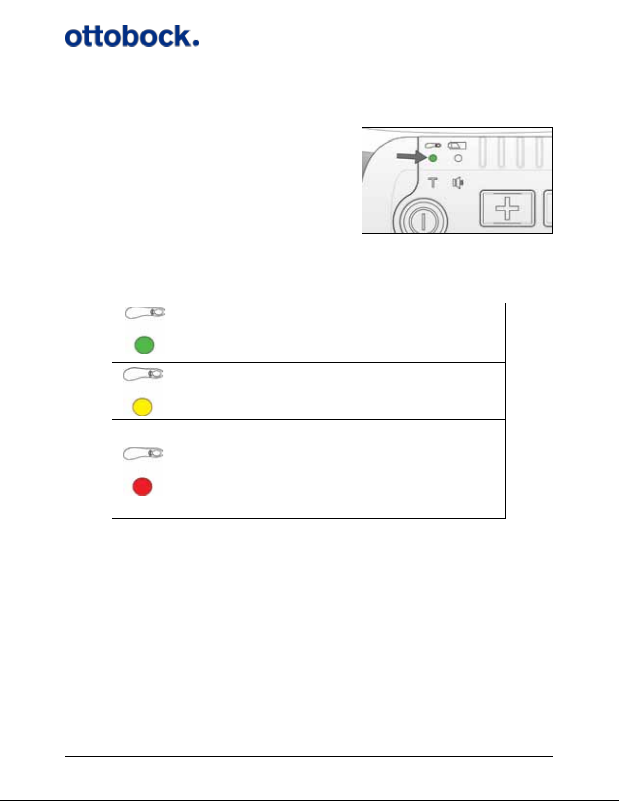
The battery indicator for the Heel Switch is shown by the top left light icon on the
Control Unit.
The Heel Switch battery indicator.
The Heel Switch battery indicator can be green, yellow or red reecting how much
power you have left on the Heel Switch.
The battery level of the Heel Switch is normal and
you have power for at least 3 months.
The battery level of the Heel Switch is medium and
you have power for at least 1 week.
Red and ashing while other light indicators are
turned o and the Control Unit beeps for 8 seconds
with an interval of 30 seconds:
The battery level of the Heel Switch is low and you
must discard the Heel Switch and replace it with a
new one.
When the Heel Switch battery level is low both this light indicator and the light
indicator for the Control Unit battery will ash for 8 seconds while all other light
indicators are switched o. You can tell which of the two batteries is low by check-
ing which one of the two is red: the Control Unit battery indicator or the Heel Switch
battery indicator.
The Heel Switch battery indicator also serves as an indicator for the Heel Switch
Feedback (see section 7.5.2 on page 37), i.e. the indicator ashes every time you
step on the Heel Switch.
Page 26
25
7.1.7 Training Mode Indicator
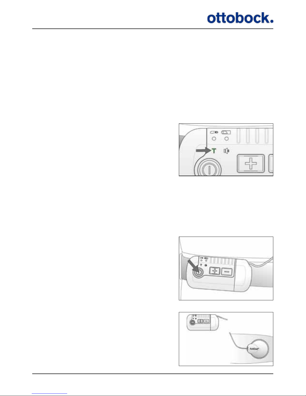
The Training Mode indicator ashes when the Control Unit is in Training Mode.
The Training Mode is used to increase your muscle strength and endurance, and
to inhibit spasticity. In Training Mode the ActiGait® Implant is cyclically activated
without an input from the Heel Switch, e.g. during sitting or lying down. Training
Mode will automatically be turned o if the Heel Switch is activated during training
so Training Mode cannot be used for walking. The duration of each activation cycle
is set by your clinician. Consult your clinician for advice about when and how to use
training mode.
The Training Mode indicator.
You must be sitting or lying down during training. You must wear the Antenna and
Control Unit but you do not need the Heel Switch. Training Mode is switched o by
pressing the on/o button on the Control Unit for 1.5 seconds.
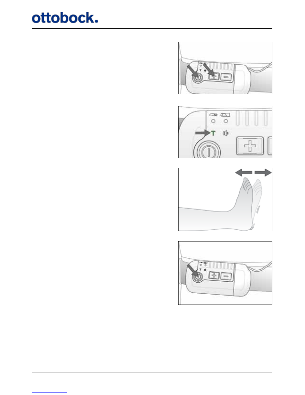
Switch o your Control Unit if it is on.
Sit or lie down in a comfortable position with
the Antenna mounted on your leg and connected
to the Control Unit. You do not need the Heel
Switch.
Page 27
26
Press the on/o button and either of the
intensity buttons at the same time for at least
1.5 seconds.
The Training Mode light indicator ashes as long
as the Control Unit is in Training Mode.
Continue training for as long as recommended
by your clinician.
Press the on/o button on the Control Unit
for 1.5 seconds to stop Training Mode.
Page 28
27
7.1.8 Mute Indicator
With the mute functionality you can switch the audio signals of the Control Unit
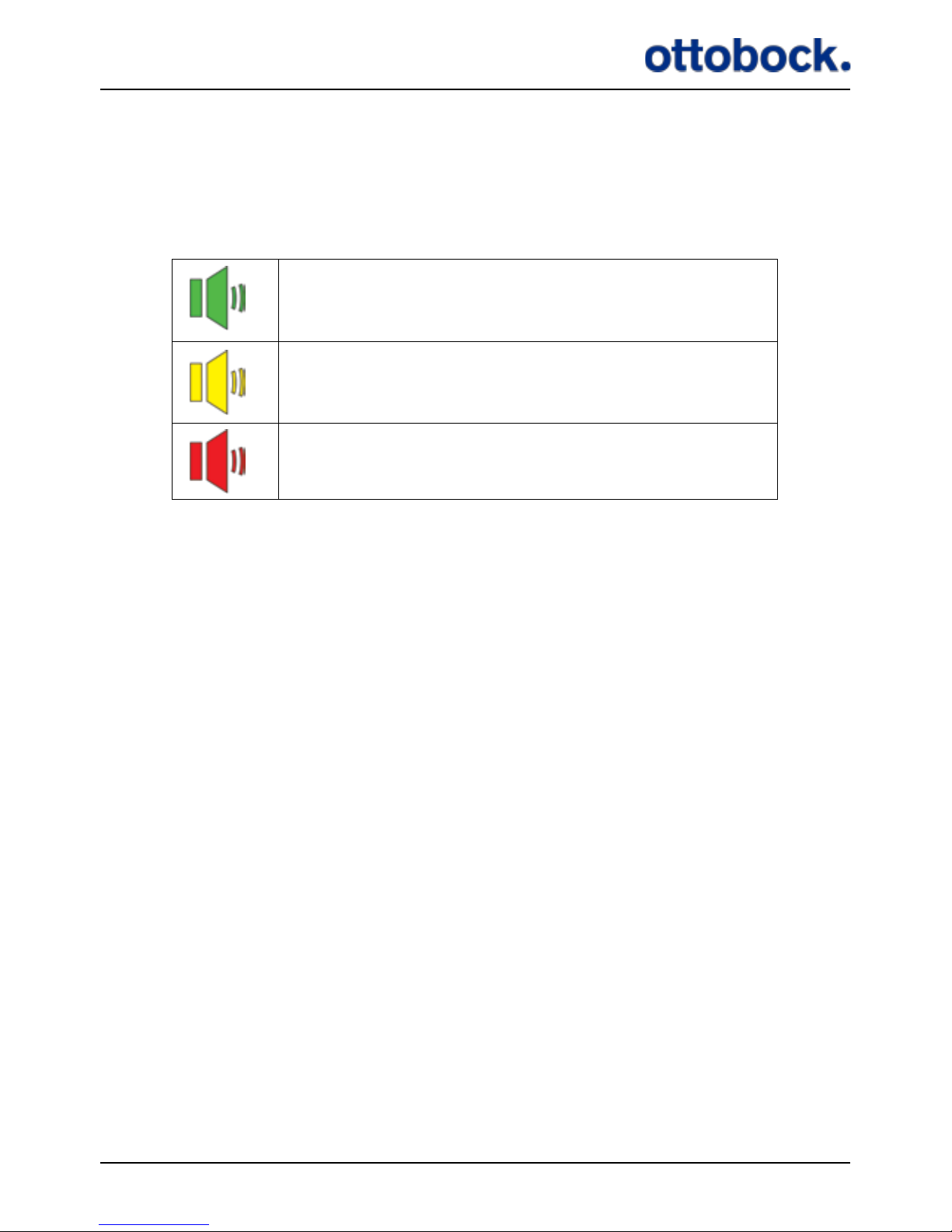
on and o according to your preference. There are 3 dierent settings and the mute
indicator shows the current setting.
All sounds are on.
All sounds are on, except for the Heel Switch feedback.
All sounds are o, except for warnings.
See section 7.7 on page 42 for further information about the audio signals and
section 7.1.3 on page 19 about how to operate the mute button.
7.1.9 Stimulation Intensity Indicators
The row of light indicators on top of the Control Unit shows the current intensity
level of the stimulation. There are 7 light indicators so the stimulation intensity can
be adjusted in 7 steps. Your clinician will set the range within which you can adjust
the stimulation intensity with the Control Unit. See section 7.1.2 on page 18
about how to adjust the stimulation intensity.
7.2 Putting On the Control Unit
You should wear the Control Unit on your waist so that you can easily access it
while walking and sitting. You can use the three dierent Control Unit Fixtures to
attach the Control Unit to your clothing, a belt or your skin or you can carry it in
your pocket. The Antenna is available in two cable lengths so that you can choose to
carry the Control Unit at the aected side or the non-aected side.
Page 29
28
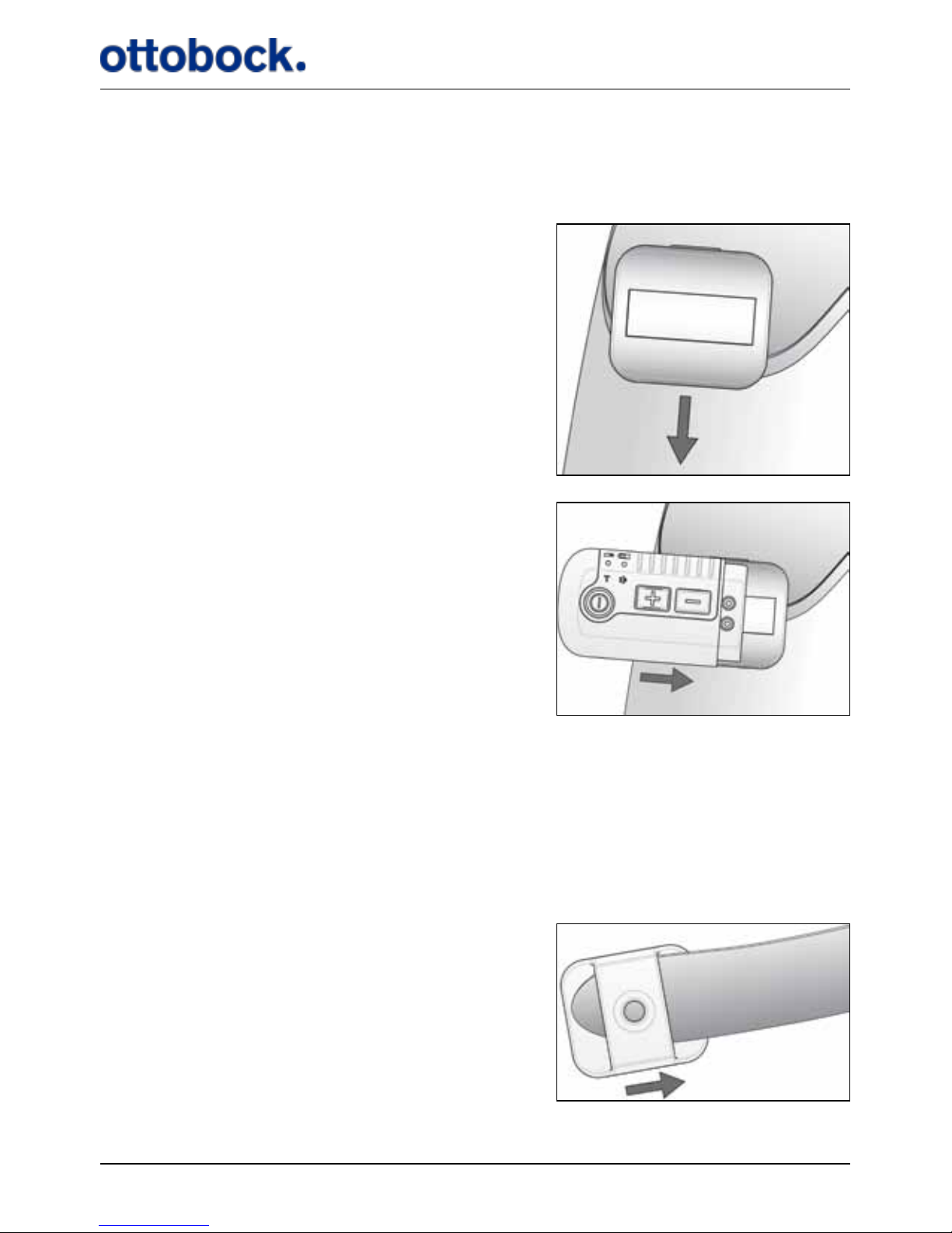
7.2.1 The Belt Clip
The Belt Clip is suitable if you want to attach the Control Unit to e.g. the waist line of
a pair of trousers or a skirt or at the lining of your pocket.
Attach the Belt Clip to your clothing, e.g.
your waistline or a pocket…
…orient the Control Unit as shown and slide
it against the Belt Clip to x the two together.
The Control Unit is held in place by magnets inside both the Control Unit and the
Belt Clip.
7.2.2 The Belt Loop
The Belt Loop is suitable if you want to carry the Control Unit on your waist and you
are wearing a belt.
Slide the Belt Loop onto your
belt as you are putting the belt on...
Page 30
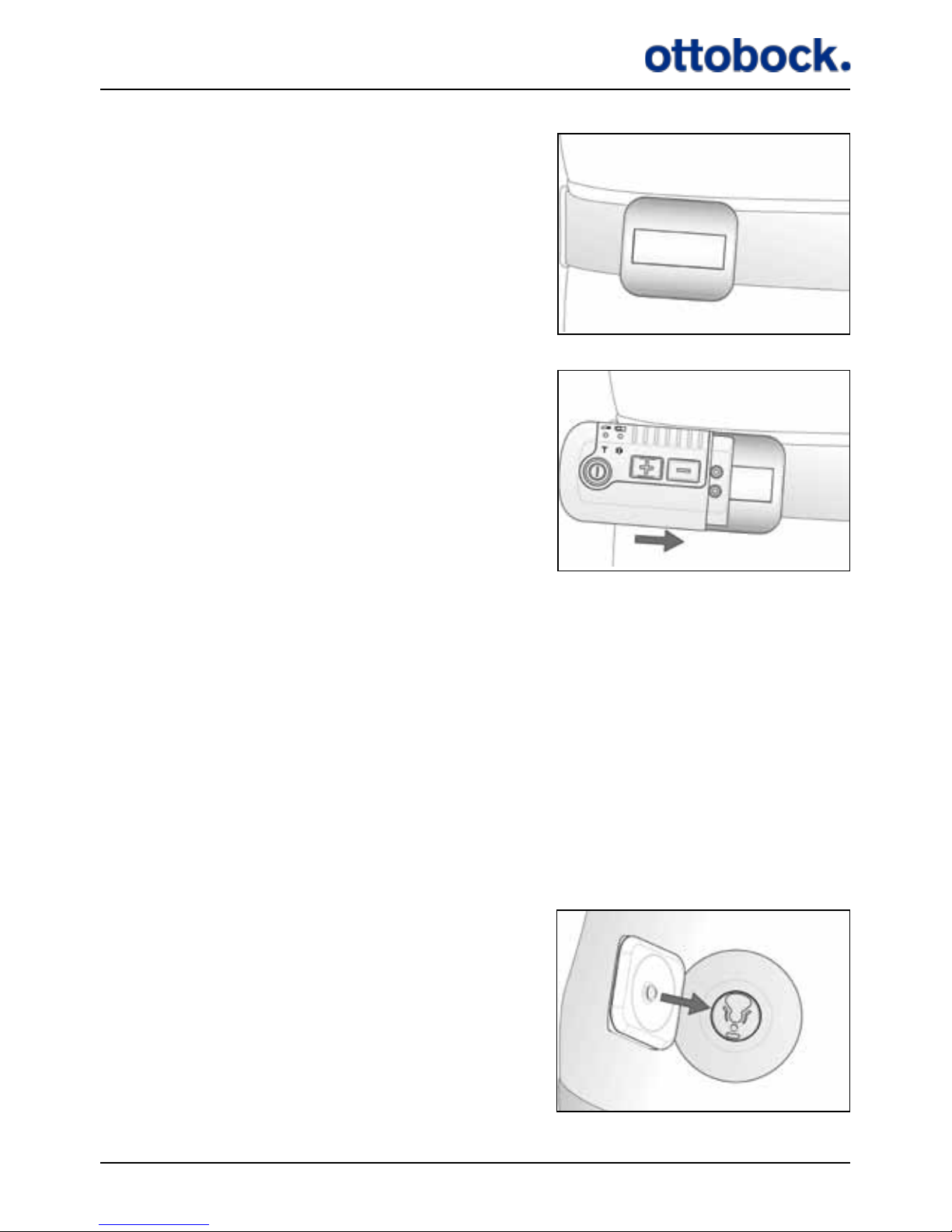
29
.
.put the belt on and slide the Belt Loop
to the right position...
...orient the Control Unit as shown and slide
it against the Belt Loop to x the two together
The Control Unit is held in place by magnets inside both the Control Unit and the
Belt Loop.
7.2.3 The Body Clip
The Body Clip is suitable if you want to carry the Control Unit discretely underneath
your clothing e.g. if you are wearing a dress. The Body Clip ts to the Antenna Fixture that is also used for attaching the Antenna to your thigh.
Put on an Antenna Fixture where you want the Control Unit to sit, e.g. on your stomach (see section 7.3 on page 30 about how to put on the Antenna Fixture).
The knob in the middle of the Body Clip
ts to the plastic part of the Antenna Fixture.
Page 31
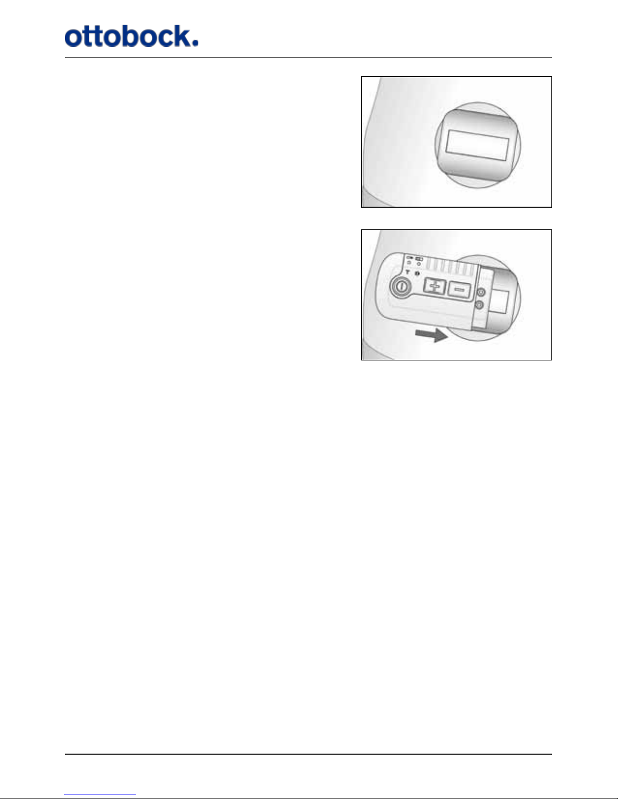
30
Insert the knob of the Body Clip into the
opening in the plastic part of the xture and
push the Body Clip downwards until you hear
a click.
Orient the Control Unit as shown and slide it
against the Body Clip to x the two together.
The Control Unit is held in place by magnets inside both the Control Unit and the
Body Clip.
7.3 Putting On the Antenna Fixture
In order for the Antenna Fixture to sit securely on the skin, the following guidelines
should be followed:
1. Wash and dry the skin thoroughly before positioning the Antenna Fixture.
2. Remove hair on the skin if the hair will prevent the Antenna Fixture from sitting
securely
3. The adhesive side of the Antenna Fixture should not be touched as this will redu-
ce its adhesiveness.
4. The use of moisturizer will reduce the adhesiveness of the Antenna Fixture.
Please note that the Antenna Fixture must not be placed on top of a wound.
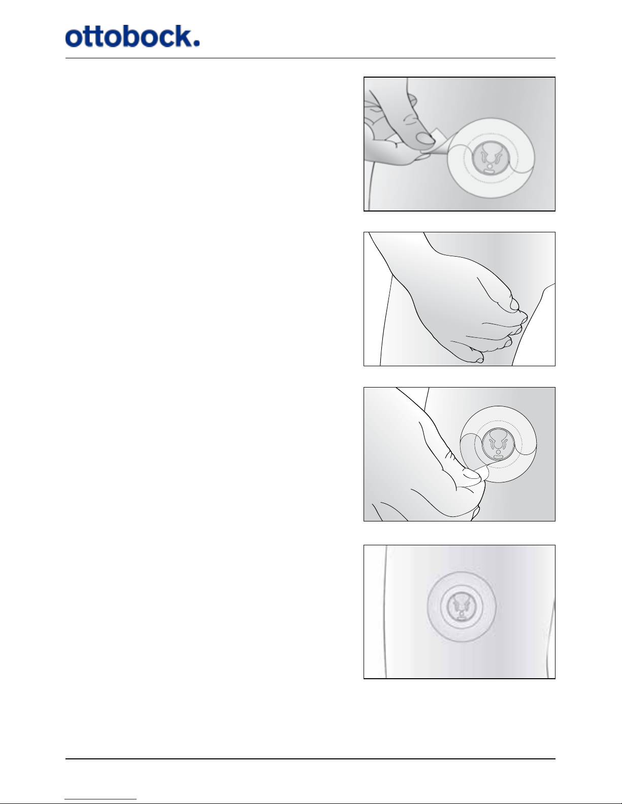
The Antenna Fixture consists of 3 layers (Figure 7). On the backside, there is a
bearing liner which protects the adhesive qualities of the Antenna Fixture. In the
middle there is an adhesive patch with a round plastic disc onto which the Antenna
is secured. On the front, there is a sti applicator liner which makes it easier to place
the Antenna Fixture.
Page 32
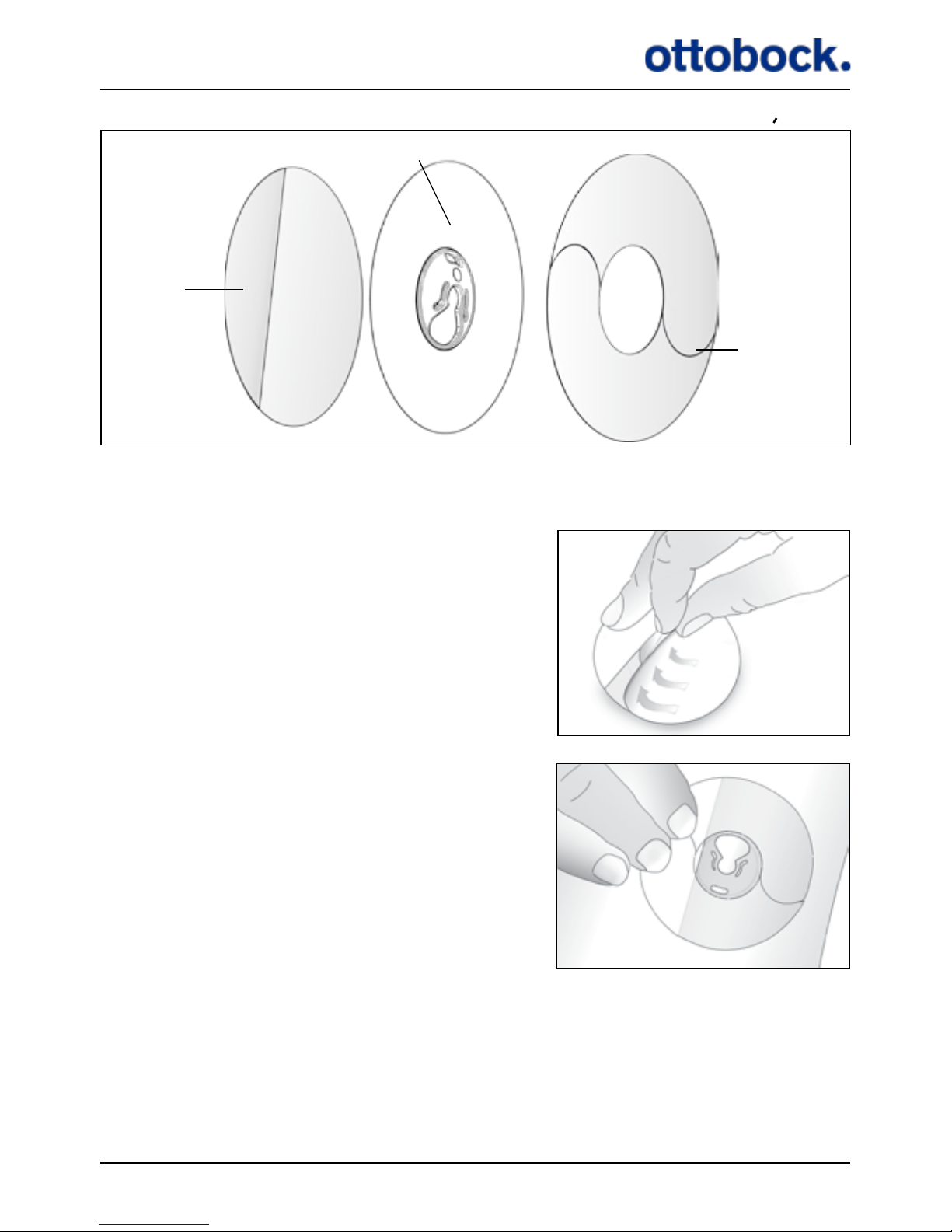
31
Place the Antenna Fixture on a table with the
bearing liner facing upwards. Peel o the rst
part of the bearing liner. Do not touch the
adhesive side as this will decrease its
adhesiveness.
Attach the Antenna Fixture on the skin on top
of the Implant by pressing the adhesive half of
the xture onto the bare skin. Orient the Antenna
Fixture so the large opening points upward.
Figure 7: The 3 layers of the Antenna Fixture
Bearing
Liner
Adhesive
Applicator
Liner
Page 33
32
Peel o the remaining part of the bearing liner.
Press the entire Antenna Fixture rmly onto
the skin to warm it up and ensure the
adhesiveness of the xture. Keep the pressure
for 30 seconds.
Finally, remove the applicator liner on the front
of the Antenna Fixture. This is done by carefully
peeling o the two halves of the applicator liner.
The Antenna Fixture is now ready for use.
Page 34
33
If you experience any skin irritation where the Antenna Fixture is placed, you
should stop using the xture and your ActiGait® for a while. If the problem contin-
ues, contact your clinician.
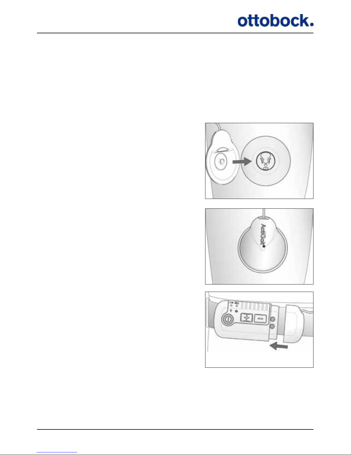
7.4 Putting On the Antenna
When you have attached the Antenna Fixture to your thigh above the Implant, you
can click the Antenna into the Fixture.
The knob in the middle of the Antenna ts into
the plastic part of the Antenna Fixture.
Insert the knob of the Antenna into the opening
in the plastic part of the xture and push the
Antenna downwards until you hear a click.
Connect the Antenna plug to the Control Unit.
Page 35
34
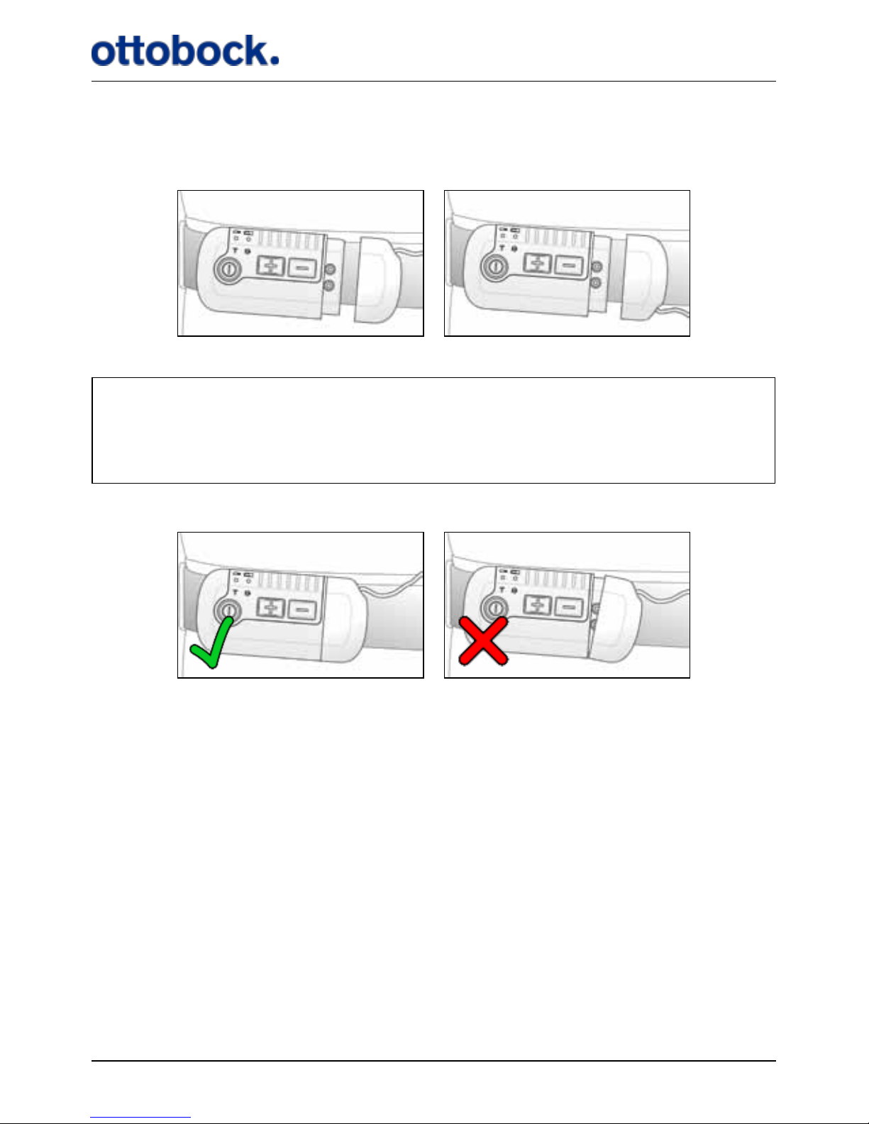
You can turn the Antenna plug both ways so that the Antenna Cable comes out at
the top or at the bottom of the Control Unit.
Make sure you attach the Antenna plug properly to ensure the connection to the
Control Unit, otherwise you will get a warning when you start to walk, meaning
that the Control Unit will beep and the stimulation intensity indicators will ash
for 8 seconds.
WrongCorrect
The Antenna plug is held in place by magnets inside both the plug and the Control
Unit
You can disconnect the Antenna plug at any time, for example, when using a rest
room. Never pull the cable to disconnect the Antenna from the Control Unit but take
hold of the plug itself. Be careful not to make any sharp bends in the Antenna cable
as this might damage the cable.
Page 36
35
7.5 The Heel Switch
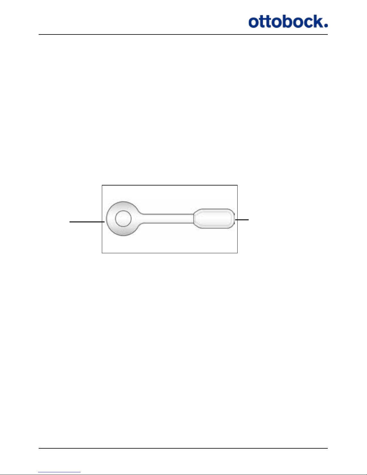
The ActiGait® Heel Switch (see Figure 8) is the device that sends information to the
Control Unit about whether the foot is on the ground or lifted. It needs to be mounted on the foot, so that the sensor is placed under the heel, and the Heel Switch
housing is placed along the ankle.
The sensor consists of a mechanical switch that activates when you put enough
weight on it, i.e. when you place your heel on the ground. The radio transmitter
transmits a radio code to the Control Unit for every heel lift and heel strike. The
Control Unit reacts by activating the stimulation which makes the muscles lift the
foot. The Control Unit and Heel Switch must be paired to communicate with each
other (see section 7.1.4 on page 21).
Figure 8: The Heel Switch
Housing with
battery and radio
transmitter
Sensor
It is essential that the Heel Switch is kept in place when you walk so that the switch
is activated and de-activated properly for every heel strike and heel lift, respectively.
The Heel Switch can be placed under either foot; however, it can only be switched
over in connection with reprogramming the Control Unit at the clinic. See section
7.5.1 on page 36 about how to place the Heel Switch and how to use the Heel
Sock.
The Heel Switch battery is not exchangeable. If you open the Heel Switch to access the battery, you will break the sealing and thereby compromise the ingress
protection against water and particles. When the battery of the Heel Switch is out
of power, the whole Heel Switch must be discarded (see section 12.3 on page 53
about disposal).
Page 37
36
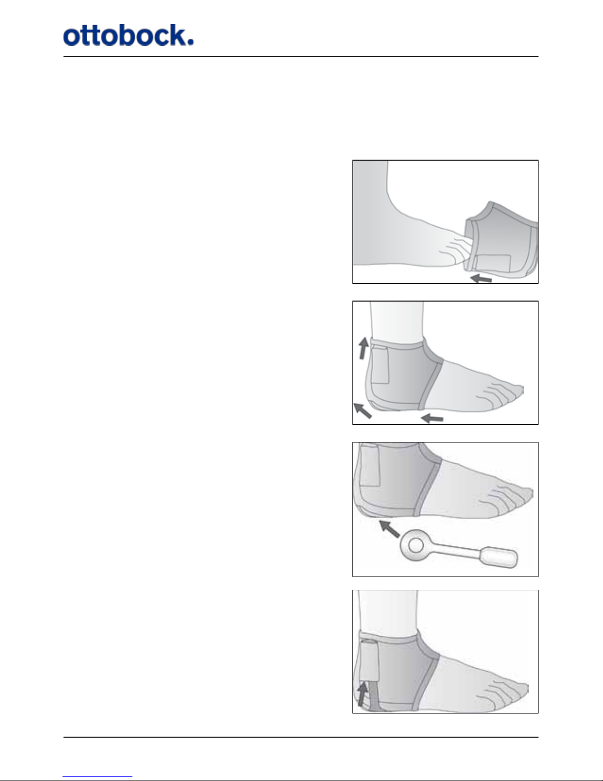
7.5.1 The Heel Sock
Your ActiGait® is delivered with a Heel Sock that keeps the Heel Switch in place. If
you choose not to use the supplied sock but just put the Heel Switch into a normal
sock, be aware that the Heel Switch could have a tendency to slide away from your
heel when you walk.
Pull the Heel Sock over your foot…
…pull it in position.
Put the round plate of the Heel Switch
into the pocket under your heel…
…and put the house of the Heel Switch into
the pocket at your ankle.
Page 38
37
Be careful not to pull the pockets of the Heel Sock. The pockets are constructed only
for holding the Heel Switch in place and not for being pulled.
7.5.2 Heel Switch Feedback
The Control Unit gives a short beep and the Heel Switch light indicator ashes for
every signal from the Heel Switch; both at heel lift and heel strike. This is called Heel
Switch feedback. It can be used to check if the Heel Switch is activated properly during
walking. The Heel Switch feedback can be muted (see section 7.1.3 on page 19).
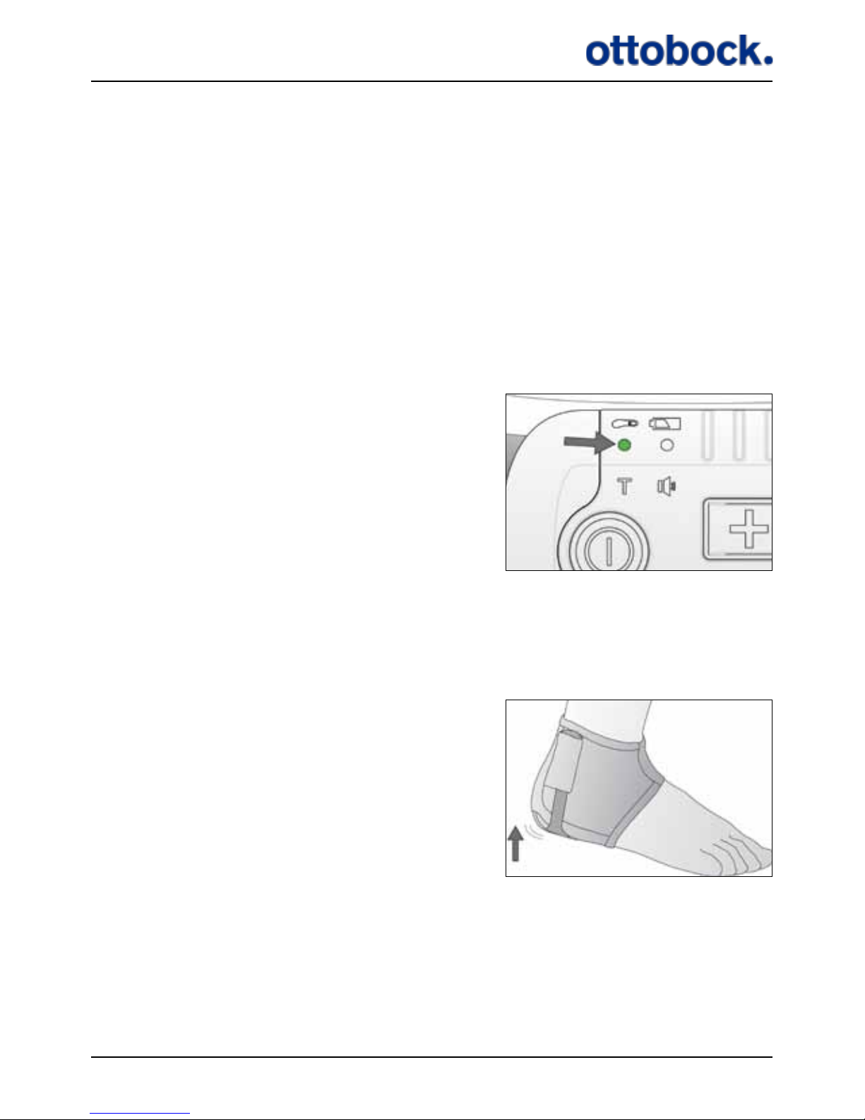
When you have put on the Heel Switch and before you start to walk, you should
check that the Heel Switch is activated when you put your weight on it.
The Heel Switch light indicator.
Make sure that the Control Unit is switched on. If the Control Unit is switched on but
no lights are on, the lights are powered down and you must press one of the buttons
to turn them back on.
Stand up with your weight on the foot
without the Heel Switch
Page 39
38
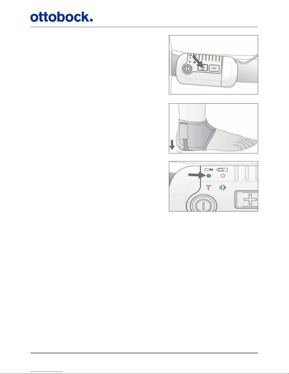
…watch the Control Unit and press a button to
make sure that the lights are not powered down…
…while you shift your weight to the Heel Switch.
Check that the Heel Switch indicator ashes
when you put your weight on the Heel Switch.
If the Heel Switch indicator does not ash, it is probably because the Heel Switch
is not placed properly under your heel. Adjust the position of the Heel Switch and
check the connection again or go to section 9 on page 49 for troubleshooting.
If the mute indicator is green, you will hear a short beep for every time you step onto
the Heel Switch and every time you step o it again, i.e. two beeps for every step.
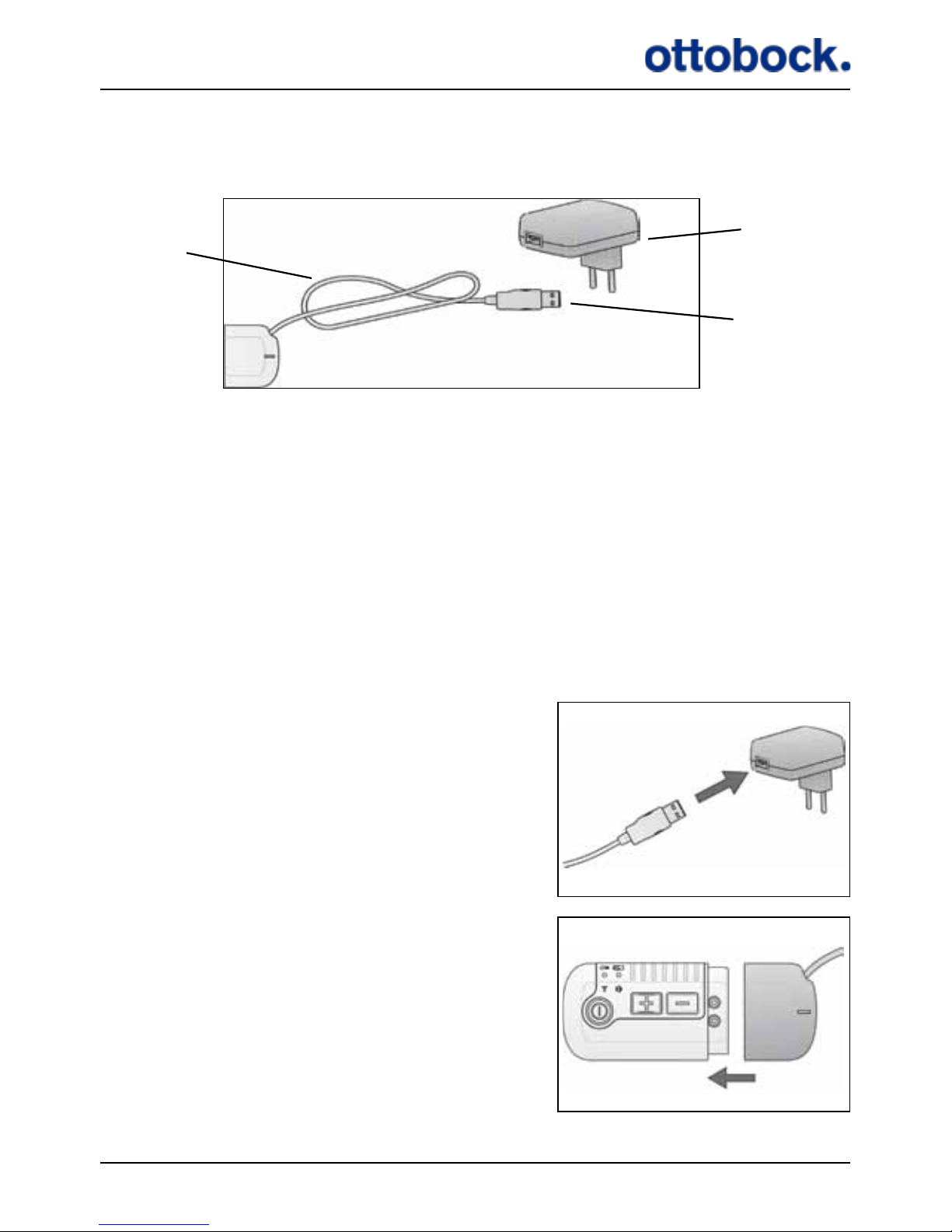
7.6 The Charger
The Control Unit is charged with the supplied ActiGait® Charger and ActiGait®
Charger Cable (see Figure 9). The Charger Cable has one light indicator that shows if
the Charger is correctly connected to the wall outlet. For safety reasons the Charger
Cable uses the same plug socket as the Antenna so you cannot use the ActiGait® for
stimulation while charging the Control Unit. Do not keep the Control Unit on your
body while charging.
Page 40
39
The Control Unit battery is not replaceable. If you try to open the Control Unit to
change the battery, you will compromise the sealing of the Control Unit.
The Charger Cable is connected to the Charger with a USB plug. The Control Unit
should only be charged with the supplied Charger and Charger Cable. If the Charger
Cable is connected to some other equipment via the USB plug, e.g. a PC, the Control
Unit might be harmed.
7.6.1 Charging the Control Unit
It is recommended that you charge the Control Unit regularly instead of waiting until
the power level is low. Charging the battery will take a maximum of 5 hours depending on how much power is left on the battery.
Connect the Charger Cable to the Charger …
…connect the Control Unit to the Charger
Cable.
Put the Charger into a wall outlet and the
Control Unit is charged.
Figure 9: The Charger and Charger Cable
USB
plug
Charger
Charger
Cable
Page 41
40
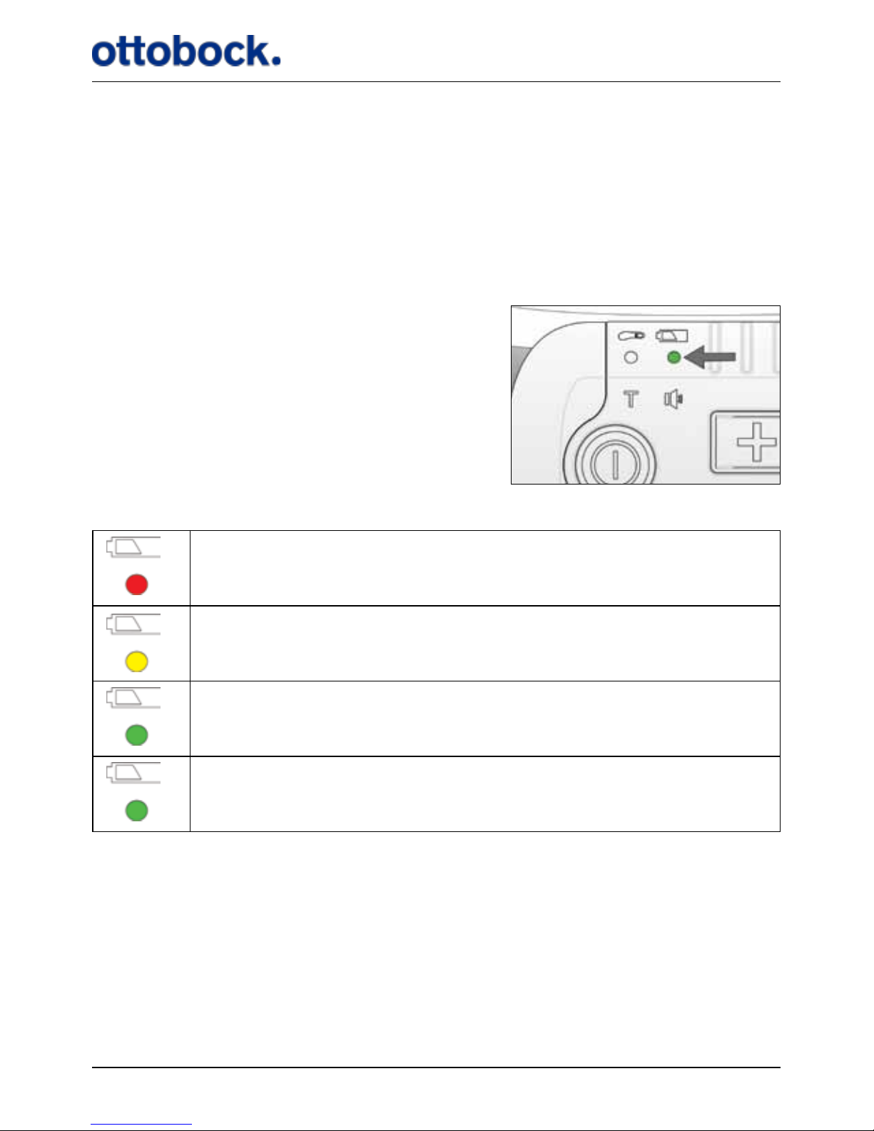
When the Charger is connected correctly to the wall outlet, the light indicator on the
Charger Cable will switch on. This means that the Charger is powered. If the Control
Unit is switched o, the Charger will switch it on to show the charging status with
the Control Unit battery indicator.
When the Control Unit is connected to the Charger, you can see the status of the
power level on the light indicator for the Control Unit battery.
Control Unit battery indicator.
Charging status:
The power level is low.
You have enough power for a short walk.
You have power for at least one day of normal use.
Flashing:
Control Unit is fully charged.
The light indicator will show a constant green light when the Control Unit is ready
for one day of normal use. It is recommended that you charge the Control Unit bat-
tery fully, i.e. until the green light starts ashing, to ensure that you do not run out
of power at an inconvenient time. However, do not hesitate to interrupt the charging
if you want to use the Control Unit for walking, it will not shorten the lifetime of the
battery to only charge it partly.
Page 42
41
Charging stops when you disconnect the Charger Cable from the Control Unit or
when the Control Unit is fully charged, i.e. the light indicator is green and ashing.
It does not harm the Control Unit or the battery to leave it connected to the Charger
Cable even though it is already fully charged.
The lifetime of the Control Unit battery is 5 years as a minimum. The capacity of a
rechargeable battery of this type becomes lower over time. When the battery is new,
it can hold power for some days of use but after 5 years it can only hold power for
one day
The Control Unit battery is not exchangeable. If you open the Control Unit to access
the battery, you will break the sealing and thereby compromise the ingress protection against water and particles. When the battery of the Control Unit can no longer
hold enough power to last for one day of use, the whole Control Unit should be
discarded (see section 12.3 on page 53 about disposal).
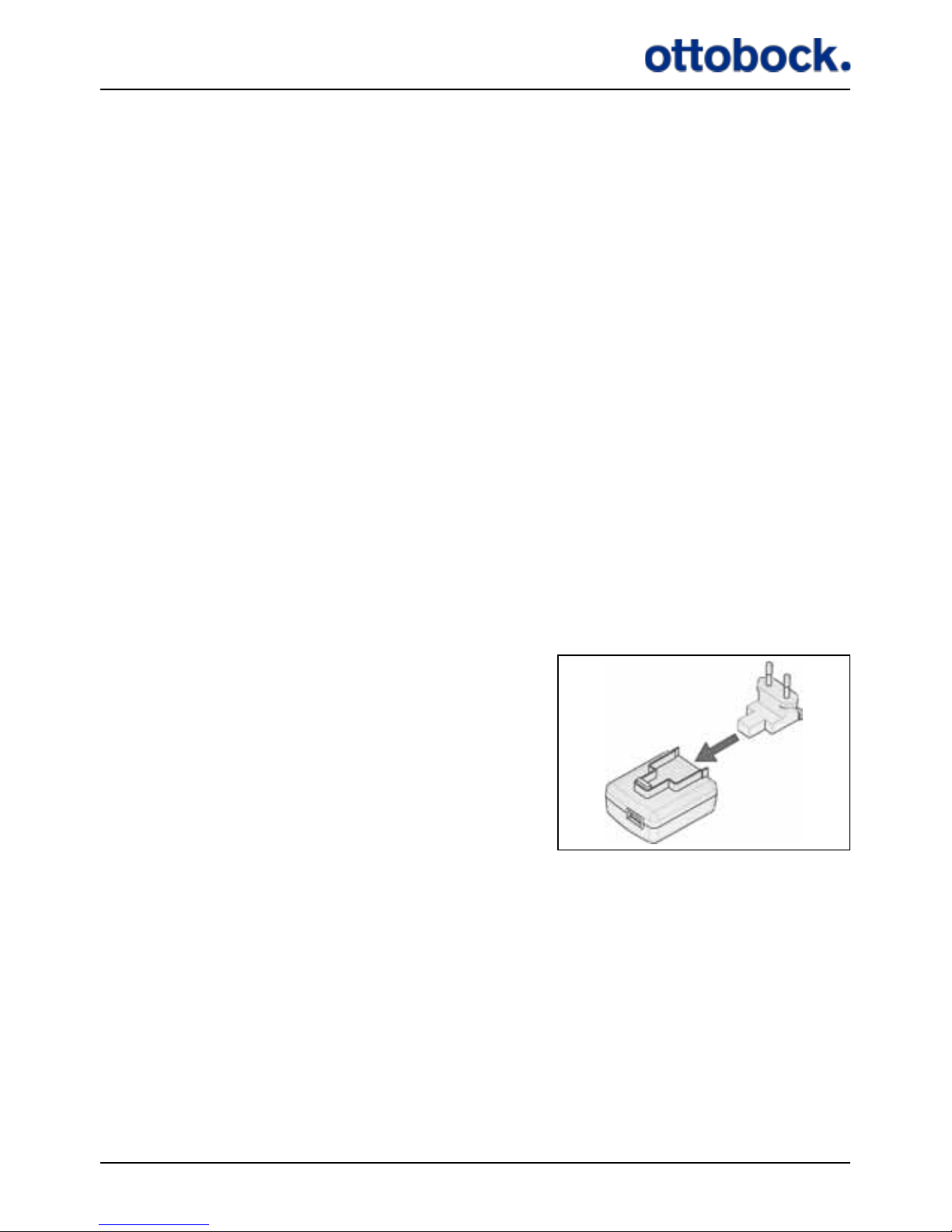
7.6.2 Travel Kit for Charger
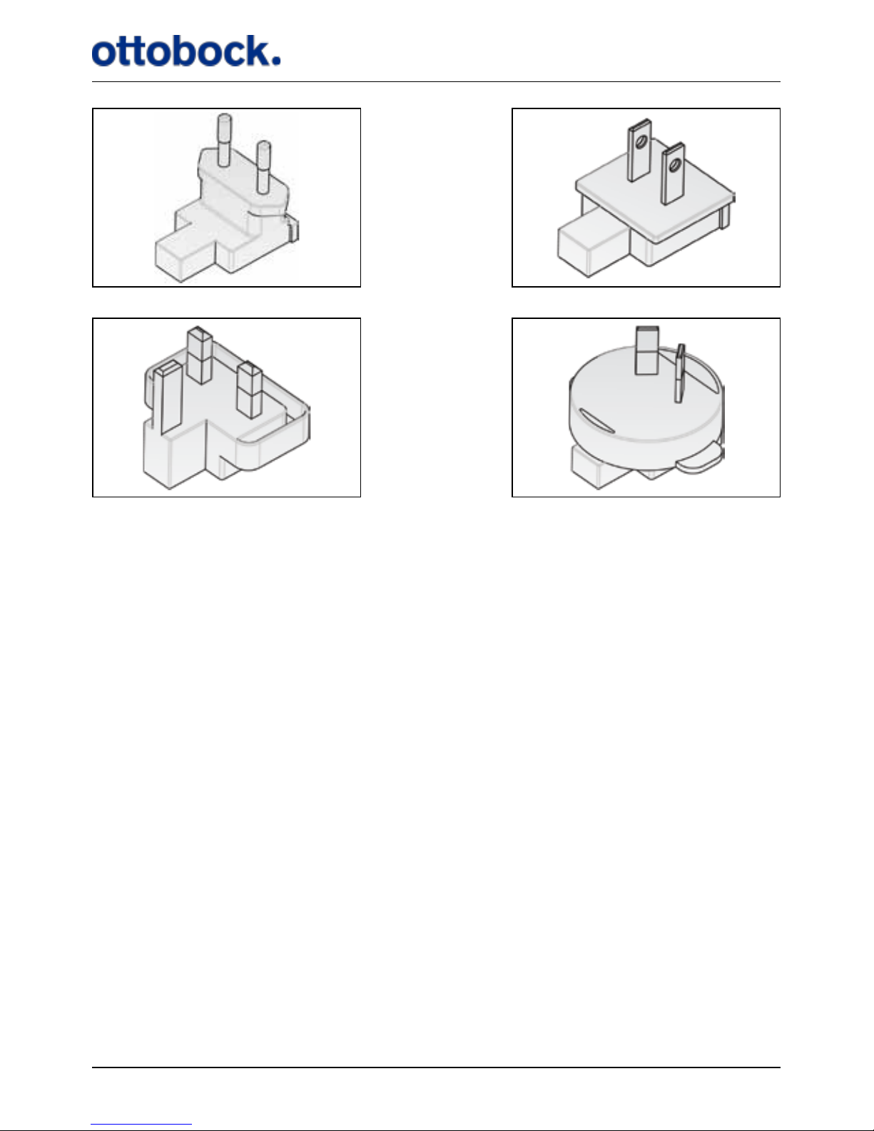
The Charger includes a travel kit with dierent wall plugs for dierent countries.
Slide the wall plug into the Charger
to connect them.
Page 43
42
7.7 Audio Signals and Warnings
The Control Unit has a number of audio signals and a warning signal. A warning
consists of short beeps for 8 seconds while some or all of the light indicators ash
depending on the reason for the warning. An audio signal is a single beep that can
be either short or long.
7.7.1 Warnings
The Control Unit will always give a warning if it receives signals from the Heel
Switch without being able to send a signal to the Antenna. This will typically be if
the Antenna is disconnected but it can also be because there is not enough power on
the Control Unit battery to send signals to the Antenna.
Reasons for warnings:
• The Control Unit is out of power. The Control Unit battery indicator is red and
ashing and the Control Unit will beep for 8 seconds with an interval of 30 seconds until you charge it. The Heel Switch battery indicator is also ashing while
all other indicators are turned o.
• Response: Charge the Control Unit as soon as possible (see section 7.6.1 on
page 39 about charging of the Control Unit).
Figure 10: Wall plug Europe
Figure 11: Wall plug UK
Figure 12: Wall plug US and Japan
Figure 13: Wall plug Australia
Page 44

43
• You start to walk while the Antenna is not properly connected to the Control Unit.
The Control Unit will beep for 8 seconds while the stimulation intensity indica-
tors ash.
• Response: Make sure that the Antenna plug is properly connected to the
Control Unit. (see section 7.4 on page 33 about the Antenna).
7.7.2 Audio Signals
The Control Unit has a number of audio signals to make it easier to adjust the settings. The audio signals mentioned in this section can all be muted but the warnings
described above cannot.
• Stimulation Intensity
• Long beep: You have pressed the intensity up button when you are already
at the maximum level
• Short beep: You have pressed the intensity down button when you are
already at the minimum level.
• Heel Switch feedback: The Control Unit gives a short beep for every signal from
the Heel Switch; both at heel lift and heel strike. This can be used to check if the
Heel Switch is activated properly during walking.
• Low battery level of the Control Unit: When the Control Unit battery indicator is
red the Control Unit will give a short beep for every 30 seconds until you charge
the battery.
• Indicator Check: Every time the Control Unit is switched on it performs an indi-
cator check. This means that all light indicators ash once and a short beep is
heard.
8. Lights and Audio Signals
The Control Unit has a number of light indicators and sounds that tell you dierent
things about the settings or status of the Control Unit and the Heel Switch. This chap-
ter contains a table of all the dierent light indicators and a table of the audio signals
and what they mean.
The tables are meant to give an overview and therefore the explanations are very
short. If you want more information please go to the chapters that are referred to in
the tables.
Page 45
44
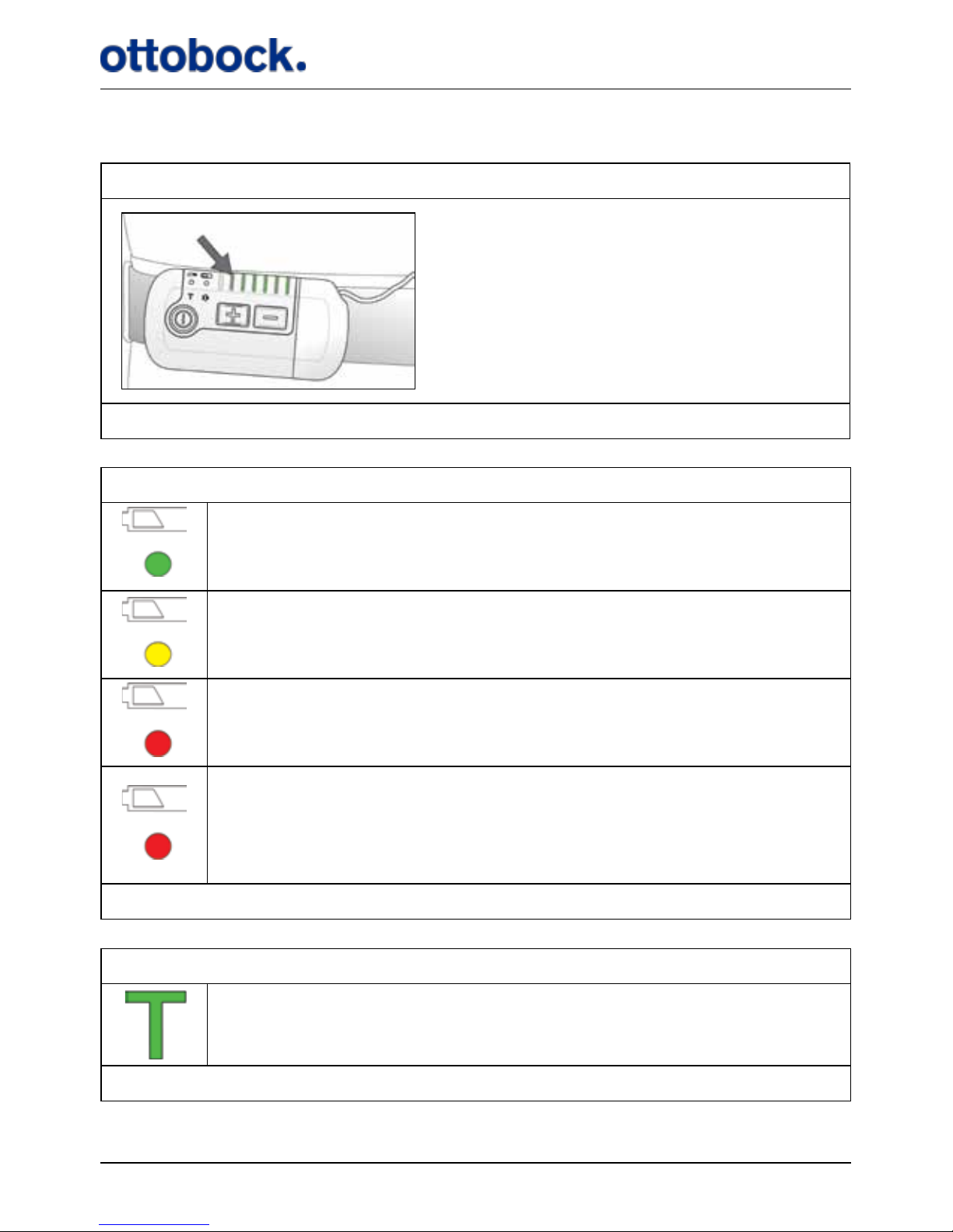
8.1 How to Interpret the Light Indicators
Battery status of the Control Unit
You have power for at least one day of walking.
You have power for less than one day.
Red and the Control Unit beeps once every 30 seconds: You have
power for less than two hours. Charge the Control Unit as soon as
you can.
Red and ashing and the Control Unit beeps for 8 seconds with an
interval of 30 seconds:
The Control Unit is out of power and stimulation has stopped. Turn
o the Control Unit until you can charge it.
See section 7.6.1 on page 39.
Training Mode
Flashing:
Training Mode is on.
See section 7.1.7 on page 25.
Stimulation intensity
The number of lights shows the current stimulation intensity.
See section 7.1.2 on page 18.
Page 46
45
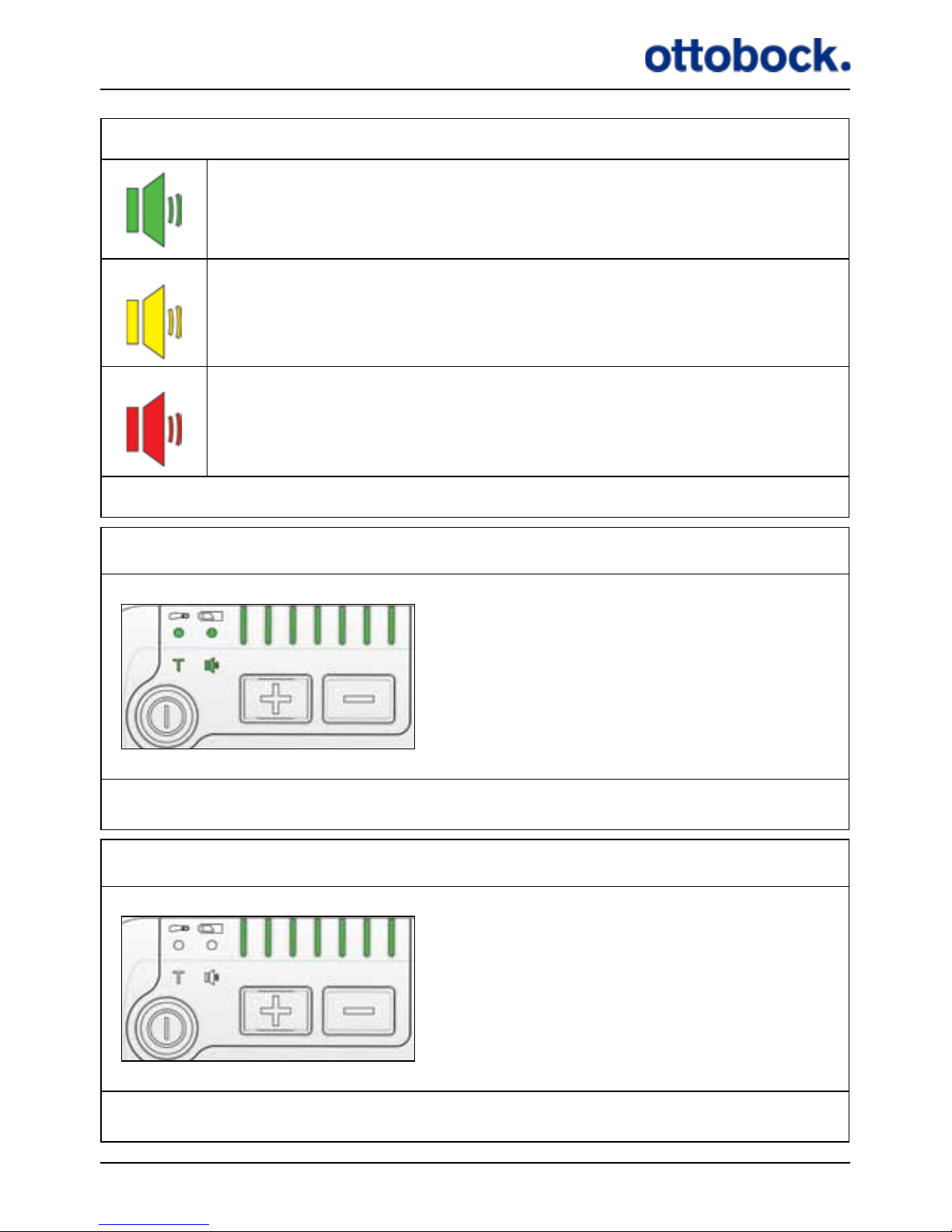
Mute
All audio signals are on.
All audio signals except the Heel Switch Feedback are on.
All audio signals are o but warnings can still be heard.
See section 7.1.3 on page 19.
Indicator check
All lights ash once when you switch
on the Control Unit:
This is the indicator check that is
performed every time you switch on
the Control Unit.
See section 7.1.1 on page 17.
WARNING
The intensity level indicators ash
and the Control Unit beeps for 8
seconds:
WARNING: The Control Unit cannot
send signals to the Implant. Check
that the Antenna is connected correctly to the Control Unit.
See section 7.4 on page 33.
Page 47
46
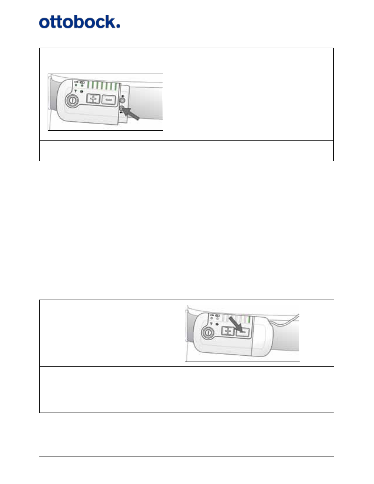
Pairing the Control Unit and Heel Switch
All lights are switched on when you
press the pairing button for the Heel
Switch. When you press the Heel
Switch they are switched o
See section 7.1.4 on page 21.
8.2 How to Interpret the Audio Signals
The Control Unit has audio signals and a warning signal. A warning means that the
Control Unit will beep for 8 seconds whereas audio signals are single beeps. Warnings can never be muted. A warning means that stimulation has stopped and you
must nd out what the warning is about and respond accordingly.
In this section you can see the dierent audio signals and warnings. The Control
Unit only has one type of sound that can be short or long, single or continuous.
Therefore, a short or long beep can mean dierent things depending on the situation. Most often the audio signals are used in combination with light signals making
it possible to interpret what the audio signal tells you.
Short beep
+
A short beep when you press the intensity down button. Only one stimulation
intensity light indicator is on:
The stimulation intensity is already at the minimum level. See section 7.1.2 on
page 18.
Page 48
47
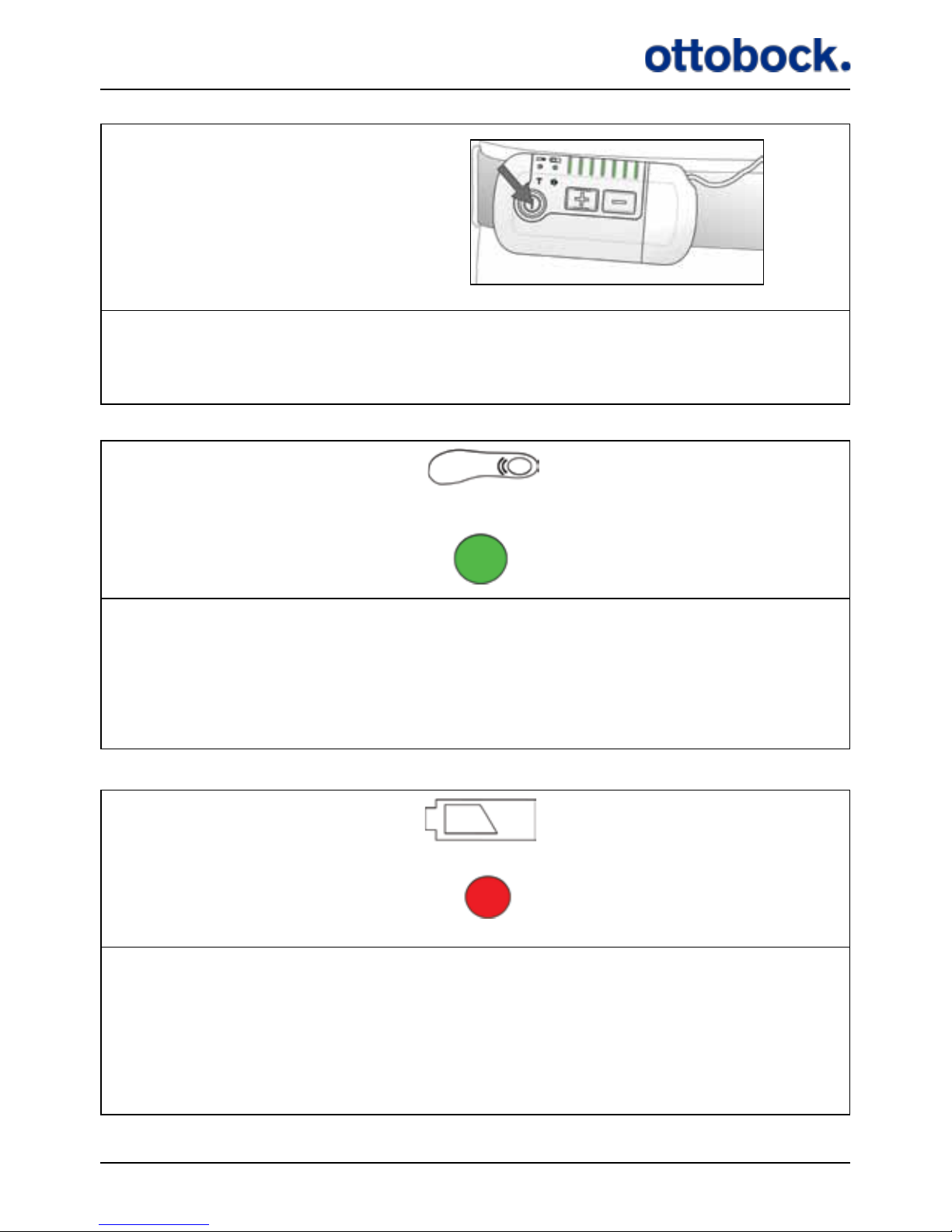
Short beep
+
A short beep when you press the on/o button for 1.5 seconds. All lights ash
once: Indicator Check. The Control Unit is now on.
See section 7.1.1 on page 17.
Short beep
+ +
ashing
A short beep when you step onto the Heel Switch and when you step o it
again. The Heel Switch battery light indicator ashes when the beeps are heard.
The color of the light indicator can be green, yellow or red reecting the Heel
Switch Battery level: Heel Switch Feedback. See section 7.5.2 on page 37.
Short beep
+
One short beep every 30 seconds. The Control Unit battery indicator is red:
Charge the Control Unit, the power level is low.
See section 7.1.5 on page 22 for more information and section7.6.1 on page
39 for charging the Control Unit.
Page 49
48
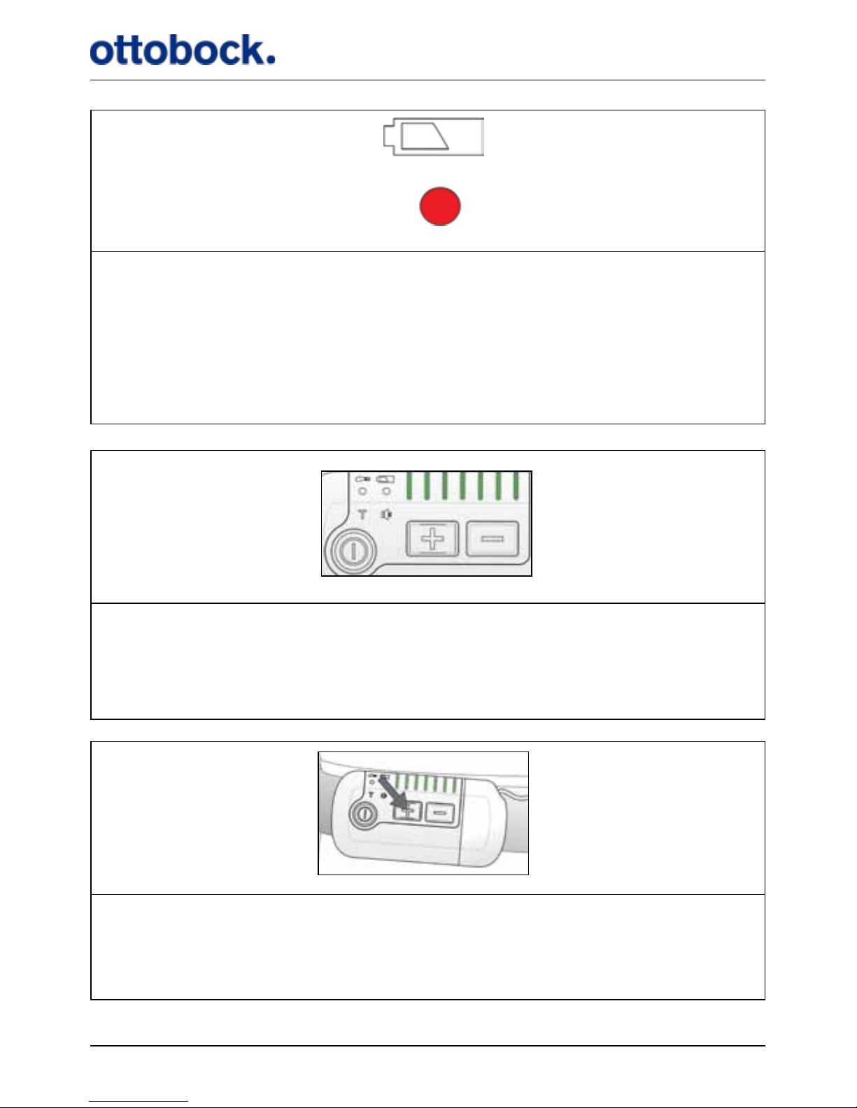
Short beeps
30 seconds
Short beeps
+ +
ashing
Short beeps for 8 seconds with a 30 seconds interval while the battery light
indicators ash. All other light indicators are turned o.
WARNING: The Control Unit is out of power and stimulation has stopped. Turn
o your Control Unit and charge it.
See section 7.1.5 on page 22 for more information and section 7.6.1 on page
39 for charging the Control Unit.
Short
beeps
+ +
Flashing
Short beeps for 8 seconds while the stimulation intensity indicators ash.
WARNING: The Control Unit cannot send signals to the Implant. Check that the
Antenna is connected correctly to the Control Unit.
See section 7.4 on page 33.
Long
beep
+
A long beep when you press the intensity up button. All stimulation intensity
light indicators are on:
The stimulation intensity is already at the maximum level.
See section 7.1.2 on page 18.
Page 50
49
Long
beep
+
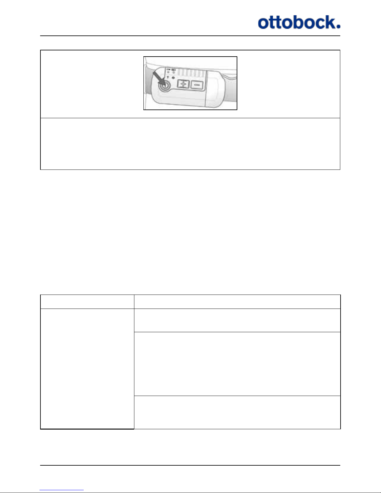
A long beep when you press the on/o button for 1.5 seconds.
The Control Unit is now turned o.
See section 7.1.1 on page 17.
9. Troubleshooting for ActiGait®
In this chapter you will nd solutions to the most common problems that you might
experience with your ActiGait®. If none of the described solutions works, or if you
experience a problem that is not described, please contact your clinician.
Check regularly if all of the equipment is intact and has no visible damage. You
should never pull the Antenna cable when you remove the Antenna from the
Antenna Fixture or the Control Unit as this can damage the cable. Take hold of the
Antenna or plug instead.
Problem Solution
You do not get a foot
lift when you are
walking
or
You do not get a foot
lift at every step
Make sure that the Control Unit is switched on (see
section 7.1.1 on page 17).
Make sure that the stimulation intensity is high
enough (see section 7.1.2 on page 18). If it is
already at the maximum, your need for stimulation
may have changed since your last visit at the clinic.
Contact your clinician for reprogramming of your
ActiGait®.
Make sure that the Antenna is placed correctly in the
Antenna Fixture above the Implant. Check that the
Antenna cable is intact and with no sharp bends.
Page 51
50
Problem Solution
Check that the Heel Switch is placed correctly under
your heel inside the Heel Sock (see section 7.5 on
page 35).
Check the connection between the Heel Switch and
the Control Unit (see section 7.5.2 on page 37).
Check that the Heel Switch works properly by press-
ing the switch with your ngers. If you cannot get a
stable response when you are walking, contact your
clinician or order a new Heel Switch.
If the Control Unit does not respond with light signals and/or audio signals when you activate the Heel
Switch:
1. Check the battery status of the Heel Switch (see section 7.1.6 on page 23) and the Control Unit (see
section 7.1.5 on page 22).
2. Repeat pairing of the Heel Switch and Control Unit
(see section 7.1.4 on page 21).
3. Replace the Heel Switch.
If the Control Unit responds with light signals and/
or audio signals when you activate the Heel Switch:
Check that the Antenna plug is properly connected
to the Control Unit.
You do not get a suf-
cient foot lift when
you are walking
Make sure that the stimulation intensity is high
enough (see section 7.1.2 on page 18). If it is
already at the maximum, your need for stimulation
may have changed since your last visit at the clinic.
Contact your clinician for reprogramming of your
ActiGait®.
Your foot is lifted too
much when you are
walking
Make sure that the stimulation intensity is low
enough (see section 7.1.2 on page 18). If it is
already at the minimum, your need for stimulation
may have changed since your last visit at the clinic.
Contact your clinician for reprogramming of your
ActiGait®.
Page 52

51
Problem Solution
You get unwanted
stimulation when you
are not walking
Adjust the position of the Heel Switch so that it does
not activate unless you stand on it
Your muscles hurt
when you walk
You may be experiencing training induced muscle
soreness, especially if you have been walking more
than usual or if you have just started using your
ActiGait®. Make sure to get enough rest so that your
muscles have time to restitute
Make sure that the stimulation intensity is low
enough (see section 7.1.2 on page 18). If it is
already at the minimum, your need for stimulation
may have changed since your last visit at the clinic.
Contact your clinician for reprogramming of your
ActiGait®
Your muscles and/or
joints hurt, also when
you are not walking
Reduce the stimulation intensity (see section 7.1.2 on
page 18) and/or walk less until the pain is reduced.
Make sure to get enough rest so that your muscles
have time to restitute. If the pain continues, contact
your clinician.
10. Warranty
Safe and eective use of the ActiGait® requires that the product be transported,
stored and used as intended, without modications, following all the manufac-
turer’s recommendations. The product must have been used and prescribed in
accordance with the ActiGait® User Manual (647G808=GB), Clinician Manual
(647G805=GB) and Surgeon Manual (647G806=GB).
The following parts of the ActiGait® are consumables with reduced warranty:
• ActiGait® Antenna Fixture
• ActiGait® Heel Sock
• ActiGait® Heel Switch
Page 53

52
In accordance with European law, the following parts are covered by a 2 year warranty:
• ActiGait® Control Unit
• ActiGait® Belt Clip
• ActiGait® Body Clip
• ActiGait® Belt Loop
• ActiGait® Antenna
• ActiGait® Charger Cable
• ActiGait® Charger
• ActiGait® Implant
11. Expected lifetime
• ActiGait® Antenna Fixture: 7-14 days
• ActiGait® Heel Sock: 50 washes
• ActiGait® Heel Switch: 1 year (depending of the intensity of use the lifetime of the
Heel Switch may vary)
• ActiGait® Control Unit: 5 years
• ActiGait® Control Unit Fixtures: 5 years
• ActiGait® Antenna: 2 years
• ActiGait® Charger Cable: 5 years
• ActiGait® Charger: 5 years
• ActiGait® Implant: 10 years
12. Cleaning, Storage and Disposal
12.1 Cleaning
The various parts of the ActiGait®should be cleaned when needed. To keep the Control
Unit, Heel Switch, Antenna, Charger, Body Clip, Belt Clip and Belt Loop clean, they
can be wiped down with a clean damp cloth. The electrical contacts in the Antenna
plug and the Control Unit should not be cleaned.
Cleaning detergents or excessive amounts of water shall be avoided. ActiGait® is designed to withstand splashes of water and moisture, but not to be submerged in water.
The Charger Cable should only be wiped with a clean, dry cloth.
Page 54
53
12.2 Storage
When the equipment is not in use, the Antenna Fixtures should be stored at a temperature between +10˚C and +27˚C for up to 6 months. The rest of the equipment
can be stored in a dry place at a temperature between +10˚C and +40˚C for up to 2
years.
In order to maintain the Control Unit battery’s ability to become fully charged, the
Control Unit must be charged with regular intervals during storage. If the Control
Unit has been in use, it must be charged with 3 months intervals.
It is recommended that the equipment is stored in the original sales boxes or the
User Suitcase to avoid accidental damage.
12.3 Disposal
The Antenna Fixtures, Heel Socks, Body Clip, Belt Clip and Belt Loop can be disposed of as household waste. The Control Unit, Antenna, Heel Switch, Charger and
Charger Cable contain batteries or electronics and shall therefore be disposed of according to the national regulations for electronic and electrical waste. The parts can
be returned to the clinician or your local ActiGait®representative.
13. Available Articles
Please contact your local ActiGait®representative to purchase any of the articles
mentioned below.
Item Part Number
ActiGait®
ActiGait®Control Unit 9002=11
ActiGait®Belt Clip 9002M=11A
ActiGait®Body Clip 9002M=11B
ActiGait®Belt Loop 9002M=11C
ActiGait®Antenna 58 cm 9002=13A
ActiGait® Antenna 78 cm 9002=13B
ActiGait®Antenna Fixtures, package of 15 pieces 9002=M03
ActiGait®Heel Switch 9002=12
Page 55

54
Item Part Number
ActiGait®Heel Sock, extra small, black 9002M=12XS-7
ActiGait® Heel Sock, small, black 9002M=12S-7
ActiGait® Heel Sock, medium, black 9002M=12M-7
ActiGait® Heel Sock, large, black 9002M=12L-7
ActiGait® Heel Sock, extra large, black 9002M=12XL-7
ActiGait® Heel Sock, extra extra large, black 9002M=12XXL-7
ActiGait® Heel Sock, extra small, whit 9002M=12XS-6
ActiGait® Heel Sock, small, white 9002M=12S-6
ActiGait® Heel Sock, medium, white 9002M=12M-6
ActiGait® Heel Sock, large, white 9002M=12L-6
ActiGait® Heel Sock, extra large, white 9002M=12XL-6
ActiGait® Heel Sock, extra extra large, white 9002M=12XXL-6
ActiGait® Heel Sock, extra small, beige 9002M=12XS-0
ActiGait® Heel Sock, small, beige 9002M=12S-0
ActiGait® Heel Sock, medium, beige 9002M=12M-0
ActiGait® Heel Sock, large, beige 9002M=12L-0
ActiGait® Heel Sock, extra large, beige 9002M=12XL-0
ActiGait® Heel Sock, extra extra large, beige 9002M=12XXL-0
ActiGait® Accessories
ActiGait® User Manual 647G808=country code
ActiGait® Charger 9002=14
ActiGait® Charger Cable 9002=15
ActiGait® User Suitcase 9002=17
Page 56
55
14. Technical Data
14.1 ActiGait® Control Unit
Dimensions 9.5 cm x 4.8 cm x 1.8 cm
Mass 80 g (including battery)
Battery Li-ion 1100mAh
Operating time
Minimum 16h after full 5 hour charging. Charging every night is recommended to ensure optimal
performance of the ActiGait®
Charging time 5 hours
Ingress IP 54
Operating temperature Between +10 °C and +40 °C
Storage temperature Between +10 °C and +40 °C
Humidity 30 – 75 % rel. H non-condensing
Short time storage and
transportation temperature
Between -20 °C and +60 °C for max 2 months
Receiver frequency 2,401MHz
Transmitter
Frequency: 2,401 MHz
Output power: 0.5 dBm
Modulation: MSK
Page 57
56
14.2 ActiGait® Belt Clip
Dimensions 5.3 cm x 4.6 cm x 1.3 cm
Mass 27 g
Operating temperature Between +10 °C and +40 °C
Storage temperature Between +10 °C and +40 °C
Humidity 30 – 75 % rel. H non-condensing
Short time storage and
transportation temperature
Between -20 °C and +60 ° C for max 2 months
14.3 ActiGait® Belt Loop
Dimensions 5.3 cm x 4.6 cm x 1.3 cm
Mass 21 g
Operating temperature Between +10 °C and +40 °C
Storage temperature Between +10 °C and +40 °C
Humidity 30 – 75 % rel. H non-condensing
Short time storage and
transportation temperature
Between -20 °C and +60° C for max 2 months
Page 58
57
14.4 ActiGait® Body Clip
Dimensions 5.3 cm x 4.6 cm x 1 cm
Mass 20 g
Operating temperature Between +10 °C and +40 °C
Storage temperature Between +10 °C and +40 °C
Humidity 30 – 75 % rel. H non-condensing
Short time storage and
transportation temperature
Between -20 °C and +60° C for max 2 months
14.5 ActiGait® Antenna
Dimensions Ø 5.7 cm x 0.7 cm
Mass 10 g
Ingress IP 54
Operating temperature Between +10 °C and +40 °C
Storage temperature Between +10 °C and +40 °C
Humidity 30 – 75 % rel. H non-condensing
Short time storage and
transportation temperature
Between -20 °C and +60° C for max 2 months
Surface temperature Max. 42.5 °C
Transmitter
Frequency: 6,772 MHz
Modulation: CW
Output power: 12.3 dBuA/m at 3 m
Page 59
58
14.6 ActiGait® Antenna Fixture
Dimensions Ø 6.2 cm x 0.4 cm
Mass 1.3 g
Storage temperature Between +10 °C and +27 °C for max 6 months
Short time storage and
transportation temperature
Between -20 °C and +60 °C for max 2 months
14.7 ActiGait® Heel Switch
Dimensions 17 cm × 2.5 cm x 0.8 cm
Mass 15.5 g
Battery Lithium coin cell type CR2032
Operating time Minimum 1 year
Transmitting range Minimum 2 m
Ingress IP 54
Operating temperature Between +10 °C and +40 °C
Storage temperature Between +10 °C and +40 °C
Humidity 30 – 75 % rel. H non-condensing
Short time storage and
transportation temperature
Between -20 °C and +60 °C for max 2 months
Transmitter
Frequency: 2,401 MHz
Modulation: MSK
Output power: 2 dBm
Page 60
59
14.8 ActiGait® Heel Sock
Sizes XS, S, M, L, XL, XXL
Washing directions
1. Maximum 40 °C normal machine wash
2. Do not bleach
3. Do not iron
4. Do not dry-clean
5. Do not tumble-dry
14.9 ActiGait® Charger Cable
Dimensions 3.5 cm x 4.7 cm x 1.8 cm
Mass 33 g
Input voltage 5 VDC
Input current 500 mA
Frequency DC
Output voltage 5 VDC
Output current Max 500 mA
Ingress IP 4X
Operating temperature Between +10 °C and +40 ºC
Storage temperature Between +10 °C and +40 °C
Humidity 30 – 75 % rel. H non-condensing
Short time storage and
transportation temperature
Between -20 °C and +60 °C for max 2 months
Page 61
60
14.10 ActiGait® Charger
Mass 50 g
Input voltage 100-240 VAC (±10 %)
Output voltage 5 VDC
Input current 75 mA
Output current Max 500 mA
Frequency input 50-60 Hz
Eciency 70 % typ. at full load
EMC
Conforms to EN 55022 + A1, CISPR 16-1, CISPR
16-2, AS/NZS CISPR 22
Output voltage tolerance ± 5 %
Operating temperature Between 10 °C and +40 ºC
Storage temperature Between 10 °C and +40 °C
Humidity 5 % to 95 % non-condensing
Short time storage and
transportation temperature
Between -20 °C and +60 °C for max 2 months
Standards
Fulls Class II SELV for the following applications: EN 60950/IEC 60950, UL 60950, VDE, CE
label
Plug connector
AC input: FRIWO exchangeable mains plug system: EURO, UK, USA/Japan, Australia
DC output: USB socket type A
Page 62
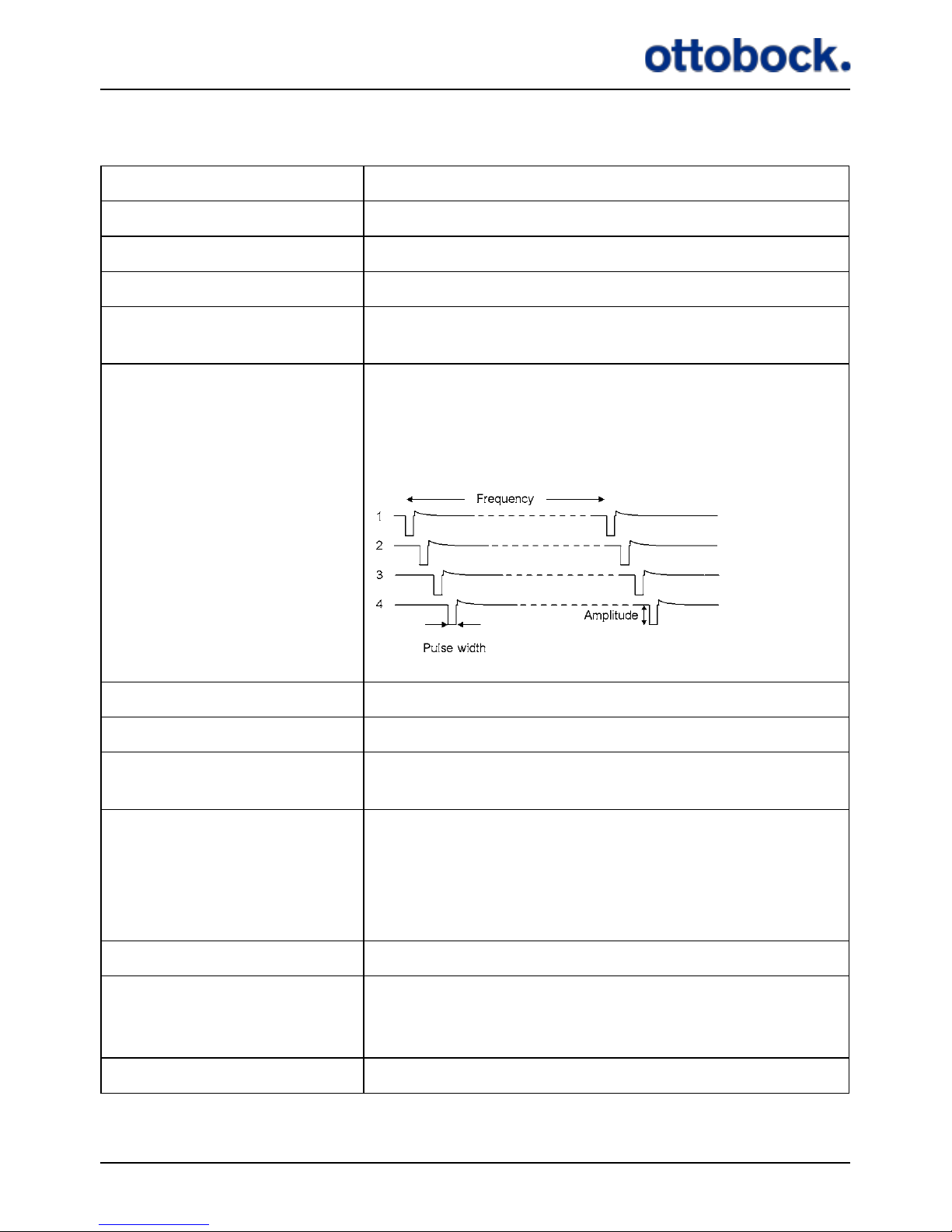
61
14.11 ActiGait® Implant
Implant length 365 mm
Implant weight 16 g
Stimulator body size Length: 60 mm Width: 30 mm Thickness: 6.2 mm
Cu length 23 mm
Cu sizes
4.5 mm, 5.4 mm, 6.4 mm and 7.6 mm (inner
diameter)
Pulse shape
Bipolar, charge-balanced. Active phase: Fixed
1.2 mA current, pulse width modulated 0-255 µs
in steps of 0.25 µs. Passive phase: Exponential
discharge (capacitive)
Number of channels 4 bipolar, interleaved
Current Amplitude of active phase = 1.2 mA
Repetition rate
5 Hz – 50 Hz, for each channel. Inter pulse interval 20-200 ms
Storage
Between +10 °C and +40 °C. Exposure to temperatures outside this range may result in Implant
malfunction. Do not expose to sunlight or other
heating sources. Store in a dry place, in original
packaging, with seal unbroken
Humidity Non-condensing
Short time storage and
transportation temperature
Between -30 °C and +70 °C for max 2 months
Receiver frequency 6,772 MHz
Page 63
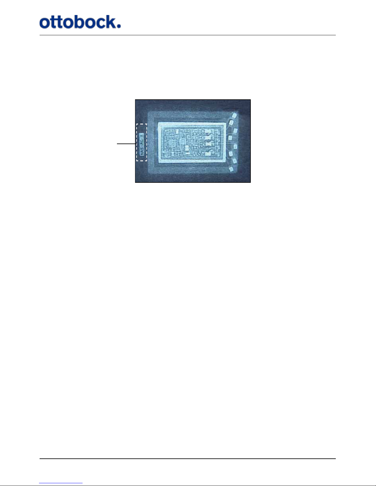
62
14.11.1 X-RayIdentication
The Implant bears a tag that is identiable by X-ray (see Figure 14). The X-ray tag
makes it possible to identify the manufacturer and the year of manufacture as required by regulations.
The format of the information on the tag is “NAS 000 Y”, where:
• NAS is the manufacturer identication, short for Neurodan A/S
• 000 is an internal reference that identies the Implant model. On Implants
manufactured later than February 2009 it says AG, short for ActiGait.
• Y is the year of manufacture represented by a letter.
• A is year 2001
• B is year 2002
• C is year 2003
• etc.
15. Classication
The ActiGait®is classied as internally powered ME equipment according to IEC/EN
60601-1.
Figure 14: The X-ray tag of the Implant
X-ray tag
Page 64
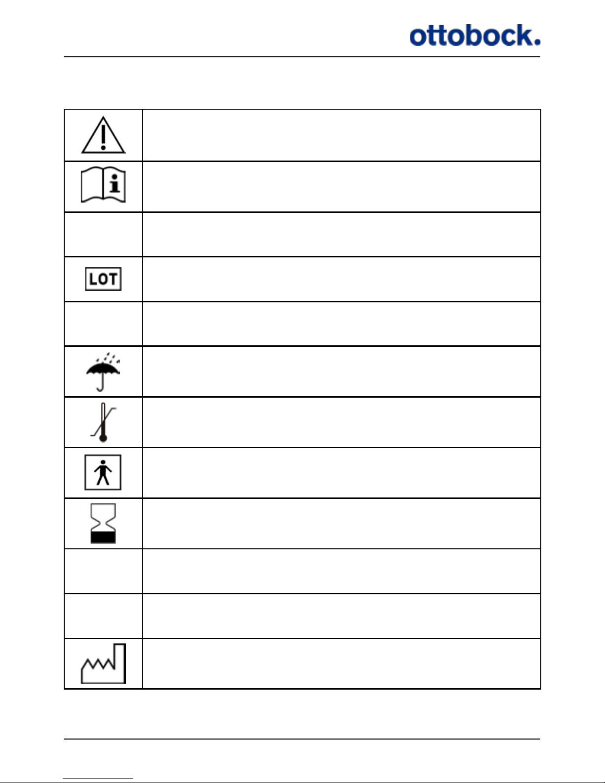
63
16. List of symbols
Caution, see instruction
Follow operating instructions, see instruction
SN
Serial number
Lot number
PN
Part number
Keep Dry
Temperature limitation
Type BF applied part
Use by/expiry date
IP 54
Protection against ingress of water and particles
IP 4X
Protection against ingress of particles
Date of manufacture
Page 65
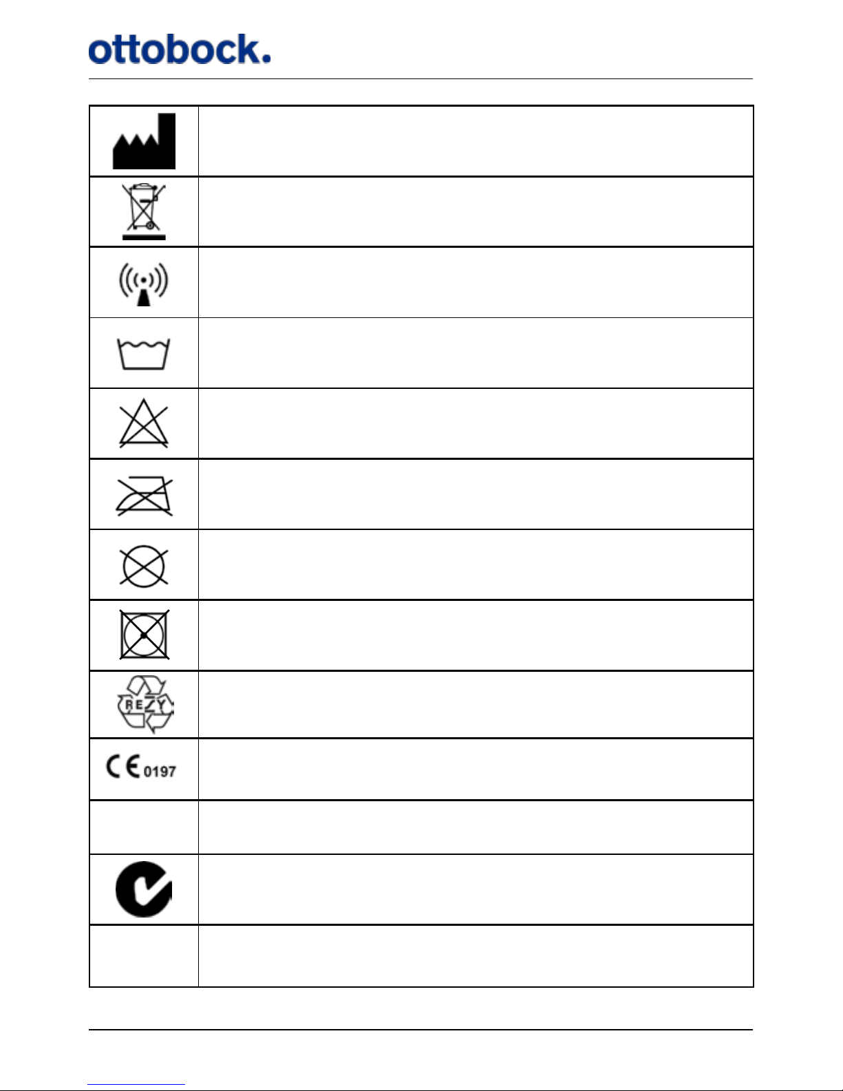
64
Manufacturer
Product contains battery, limitations on disposal of battery
The device includes RF transmitter(s)
40°
Maximum 40 °C normal machine wash
Do not bleach
Do not iron
Do not dry clean
Do not tumble dry
Recycle
In compliance with the applicable European directives
FCC
FCC ID number
C-tick
IC
IC ID number
Page 66
65
16.1 Ingress Protection
The IP (Ingress Protection) classication marked on the various parts of the ActiGait® denes the degree of protection against ingress of water and particles. The
rst number denes the protection against particles and the second number denes
the protection against water.
Classication Denition
IP 54
Particles:
5: Dust protected. Ingress of dust is not totally
prevented, but dust shall not penetrate in a quantity to interfere with satisfactory operation of the
apparatus or to impair safety.
Water:
4: Protected against splashing water. Water
splashed against the enclosure from any direction
shall have no harmful eects.
IP 4X
Particles:
4: Protected against solid foreign objects of 1.0
mm Ø and greater. The object probe of 1.0 mm Ø,
shall not penetrate at all.
Water:
X: Protection against ingress of water is not relevant.
17. Declaration of Conformity
This device complies with Part 15 of the FCC rules and RSS-210 IC rules. Operation
is subject to the following two conditions:
1. This device may not cause harmful interference.
2. This device must accept any interference received, including interference that
may cause undesired operation.
This ISM device complies with Canadian IES-001.
This device also complies with:
• 90/385/EEC for active implantable medical devices amended by 2007/47/EC
• 99/5/EC for R&TTE.
Page 67

66
Page 68

67
Page 69

Manufacturer:
ActiGait® is a product made by the Danish manufacturer Neurodan A/S. Development and
production is carried out with the highest possible diligence and in compliance with existing
European directives and national medical devices laws and regulations. Warranties and other
claims will be covered by the manufacturer if not explicitly stated otherwise.
Neurodan A/S is a Member of the Otto Bock Group and committed to “Quality for Life”. The
Otto Bock Group logo will therefore be used in respective presentations.
Neurodan A/S
Soendalsvej 85 | DK-9200 Aalborg SV | Denmark
Phone (+45) 70 27 22 97 | Fax (+45) 70 27 22 17
[email protected] | www.neurodan.com
Neurodan A/S has been certied by TÜV Rheinland LGA Products GmbH.
647G808=US Draft ver. 1.0 / 2012
 Loading...